

Amateur Radio Today - Free and Open Source Software
Amateur Radio Today - Free and Open Source Software
Amateur Radio Today - Free and Open Source Software
- No tags were found...

You also want an ePaper? Increase the reach of your titles
YUMPU automatically turns print PDFs into web optimized ePapers that Google loves.
Constr uction<br />
•<br />
Photo B. Close-up I'il'w of 11(' '()(JJiIlK coil,<br />
lion of inductance <strong>and</strong> capacitance shunted<br />
in parallcl 10 g round. This is most effective<br />
since it is basically a custom-made antenna<br />
tuner. I recently experime nted with this design<br />
<strong>and</strong> found it to be very successful. To<br />
make this addition. simply locale a variable<br />
air cap having somewhere between 15 <strong>and</strong><br />
600 pF <strong>and</strong> mount it ei ther d irectly on the<br />
car or on an enlarged platform able to hold<br />
borb. Wire them in para llcl <strong>and</strong> yo u ' re<br />
read y 10 go.<br />
lve been able (0 tune the existing center<br />
loads across each entire b<strong>and</strong> with at least a<br />
1.2; I SWR. Not bad for a $2 add ition!<br />
Before you begin. I'd like 10 note that designing<br />
<strong>and</strong> bu ilding antennas is a learning<br />
experience. We've all heard the story of the<br />
damaged antenna lying on the g round that<br />
worked better than when it was on the lower.<br />
Antenna performance is ne t always pred<br />
ictable, so watch for unusual results.<br />
There are many opinions <strong>and</strong> approaches<br />
to what works or doesn 't work. w hat 's impo<br />
rtant to remember is that the ante nna is<br />
only as good as its SWR <strong>and</strong> RSTs.<br />
Preparation <strong>and</strong> assembly of Ihe antenna<br />
is straightforward. First gathe r the materials.<br />
I strongly suggest Ihat Ihe lower porlion<br />
of the antenna be made of OIl least 3/8"<br />
d ia me te r SOLI D a luminum o r stainless<br />
steel rod. Thinner d imensions will tend 10<br />
break under the stress of d riving.<br />
The length of this rod (62- 1/2") wi ll be<br />
an overall 63-1/2" when the couplers are 011<br />
tached. T he upper whip sec tio n measures<br />
50- 1/2" overal l. This inclu des the coupler.<br />
so measure appropriately. If you need to deviate<br />
slightly from these figures no recalculation<br />
will be nece ssary. j ust allow mo re<br />
turns o n the loading coil. Later you can trim<br />
the coil to accommodate the changes.<br />
At this po int you'll need a lap <strong>and</strong> d ie set<br />
(see the sidebar). If you don't have one the<br />
local hardware store will usually do Ihe<br />
work for a small fcc. Or vis it the local high<br />
school meta l shop. T he teachers arc often<br />
very helpful <strong>and</strong> a donation of a few pizzas<br />
to the class can go a long way. Die cut a<br />
3/8· 16 thread around both ends of the lower<br />
solid antenna portion. (Reme mber to keep<br />
in mind that TWO couplers are used on this<br />
section <strong>and</strong> that the overall required length<br />
is 63-1/2".)<br />
The top antenna whip can be purchased<br />
at most radio shops or at <strong>Radio</strong> Shack; or,<br />
yo u may have o ne lying around that will<br />
work. T he majority w i ll use a 1/4 - 20<br />
thread. A coupler of the same thread will be<br />
used to attach this to the top of the load ing<br />
coi l.<br />
1 suggest you use d ielectric for all threaded<br />
connections . About a month after I installed<br />
the ant enna I began having problems<br />
while tuning up. I found that this was because<br />
the threaded po rtions had some minor<br />
corrosion due to weathe r. Pe ri odic a ll y<br />
check these connections <strong>and</strong>. if necessary.<br />
treat them with e lectrical sealer o r doping.<br />
Muunting Bracket<br />
The actual mounting bracket design will<br />
depend on where yo u dee ide to place the<br />
antenna on you r car. Like many cars, mine<br />
has rubber bumpers. This forced me to design<br />
a bracket using 1-1/2" x 3/32" nat steel<br />
that would be bent to mount against the<br />
body BEHIND the rear bumper.<br />
First bend the steel to fi t as you wo uld<br />
like it. Then measure how far o ut it needs<br />
to be cut to suppon the antenna. Ensure that<br />
the steel doesn't rub against other pans of<br />
the car-this would cause static <strong>and</strong> could<br />
effect the tuning of the antenna.<br />
After Ihe final placement <strong>and</strong> bend ing is<br />
co mpleted, drill two 7/16" ho les through<br />
the stecl <strong>and</strong> body of the car. Temporarily<br />
attach the bracket <strong>and</strong> determine ho w far<br />
out to drill the hole for mounting the antenna.<br />
Mark this spot.<br />
The size of ho le 10 drill here will depend<br />
on Ihe o utside diamete r of the ins ulating<br />
tubing you use around the mounting bo ll.<br />
The tubing I used had an o.d. of 1/2". This<br />
hole should allow Ihe insul ating tubing 10<br />
have a snug fit. so cut the hose to the thickncssof<br />
the steel plus 1/8".<br />
Drill a second hole (1/4") about 1- 1/2"<br />
from the fi rst, to ward the car. This will be<br />
for mounting the coaxial ground ing connection.<br />
After all the bending <strong>and</strong> drilling is completed,<br />
paint the bracket with as many coats<br />
of clear enamel as necessary to prot ect it<br />
from Ihe weather. Set it aside 10 dry.<br />
Next, attach two electrical connectors to<br />
one end of the 16-1 12" RG-58 coax; 3/8" to<br />
the center lead <strong>and</strong> 3/16" to the shield ing. I<br />
suggest soldering the ground connector as<br />
close as possible 10 Ihe coax. Be careful nor<br />
to me lt the center lead insulation.<br />
Once the bracke t is d ry. assemble the<br />
3/8" coupler as sho wn in Figure I. When<br />
you tighten the coupler the plastic washers<br />
will co mpress against the rubber hose <strong>and</strong><br />
electrically insulate the bo lt.<br />
T hen a tt ach th e sh ie lde d s ide to the<br />
bracket with a 1/4" bolt. Measure the resis-<br />
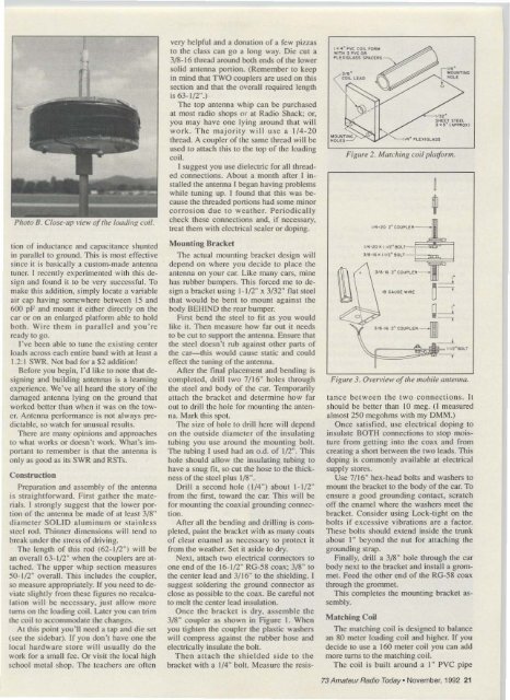
, K 4 · O'YC COIL FOOl"<br />
. !TH 'O'YC 001<br />
PLU~.SS SNCEotS<br />
~;:;) ~u.::X=- II. · PLE"GL-US<br />
' .... 20 . , ln . ftOL T-=~~<br />
, / 1H ' • , 1/2' ftOLT_<br />
•<br />
1ft GAuGE w ' ~ E<br />
'Ill ·.. 2' COU PL E ~--III<br />
- ln 2 '<br />
SHEtT STEEL<br />
, .s· (......uX!<br />
Figure 2. Ml1tchillK coil platform.<br />
"<br />
•<br />
~<br />
'Ifl·--.T<br />
Figure 3. Own ';ew ofthe mobile lllltellllQ.<br />
tance be tween the two connect ions. It<br />
should be better than 10 meg. (I measured<br />
almost 250 megohms with my DMM.)<br />
Once satisfied. use electrica l doping to<br />
insulate BOTH connectio ns 10 slop moisture<br />
from gett ing into the coa x <strong>and</strong> from<br />
crea ting a shon between the two leads. This<br />
doping is commonly available at e lectrical<br />
supply stores.<br />
Use 7/ 16" hex-head bo lts <strong>and</strong> washers to<br />
mount the bracket 10 the body of the car. To<br />
ensure a good grounding co ntact. scratch<br />
off the enamel where the washers meet the<br />
bracket . Consider using Lock-tight on the<br />
bo lts if e xcessive vibration s are a factor.<br />
These bolts should extend inside the trunk<br />
about I" beyond the nul for attac hing the<br />
ground ing strap.<br />
Finally, dri ll a 3/8" ho le through the car<br />
body next to the bracket <strong>and</strong> install a grommel.<br />
Feed the o ther end of the RG-58 coax<br />
through the grommet.<br />
This completes the mounting bracket assembly.<br />
Matching Co il<br />
I<br />
f<br />
The matching coil is designed to balance<br />
an 80 meter loading coil <strong>and</strong> higher. If yo u<br />
decide to use a 160 meter coil you can add<br />
more turns 10 the matching co il.<br />
The coil is bui It around a I" PVC pipe<br />
73 <strong>Amateur</strong> <strong>Radio</strong> toasv»Novem be r, 1992 21


