Welded Steel Tanks for Oil Storage
Welded Steel Tanks for Oil Storage
Welded Steel Tanks for Oil Storage
- No tags were found...

You also want an ePaper? Increase the reach of your titles
YUMPU automatically turns print PDFs into web optimized ePapers that Google loves.
3-6 API STANDARD 650<br />
●<br />
●<br />
In SI units:<br />
215t<br />
----------------- b<br />
( HG) 0.5<br />
where<br />
t b = thickness of the annular plate (see 3.5.3), in mm,<br />
H = maximum design liquid level (see 3.6.3.2), in m,<br />
G = design specific gravity of the liquid to be stored.<br />
In US Customary units:<br />
390t<br />
----------------- b<br />
( HG) 0.5<br />
where<br />
t b = thickness of the annular plate (see 3.5.3), (in.),<br />
H = maximum design liquid level (see 3.6.3.2), (ft),<br />
G = design specific gravity of the liquid to be stored.<br />
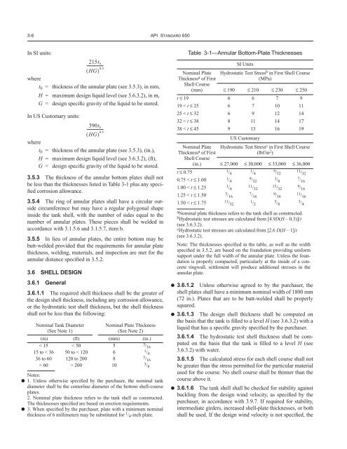
3.5.3 The thickness of the annular bottom plates shall not<br />
be less than the thicknesses listed in Table 3-1 plus any specified<br />
corrosion allowance.<br />
3.5.4 The ring of annular plates shall have a circular outside<br />
circumference but may have a regular polygonal shape<br />
inside the tank shell, with the number of sides equal to the<br />
number of annular plates. These pieces shall be welded in<br />
accordance with 3.1.5.6 and 3.1.5.7, item b.<br />
3.5.5 In lieu of annular plates, the entire bottom may be<br />
butt-welded provided that the requirements <strong>for</strong> annular plate<br />
thickness, welding, materials, and inspection are met <strong>for</strong> the<br />
annular distance specified in 3.5.2.<br />
3.6 SHELL DESIGN<br />
3.6.1 General<br />
3.6.1.1 The required shell thickness shall be the greater of<br />
the design shell thickness, including any corrosion allowance,<br />
or the hydrostatic test shell thickness, but the shell thickness<br />
shall not be less than the following:<br />
Nominal Tank Diameter<br />
(See Note 1)<br />
Nominal Plate Thickness<br />
(See Note 2)<br />
(m) (ft) (mm) (in.)<br />
< 15 < 50 5 3 / 16<br />
15 to < 36 50 to < 120 6 1 / 4<br />
36 to 60 120 to 200 8 5 / 16<br />
> 60 > 200 10 3 / 8<br />
Notes:<br />
1. Unless otherwise specified by the purchaser, the nominal tank<br />
diameter shall be the centerline diameter of the bottom shell-course<br />
plates.<br />
2. Nominal plate thickness refers to the tank shell as constructed.<br />
The thicknesses specified are based on erection requirements.<br />
3. When specified by the purchaser, plate with a minimum nominal<br />
thickness of 6 millimeters may be substituted <strong>for</strong> 1 / 4 -inch plate.<br />
Table 3-1—Annular Bottom-Plate Thicknesses<br />
Nominal Plate<br />
Thickness a of First<br />
Shell Course<br />
(mm)<br />
SI Units<br />
Hydrostatic Test Stress b in First Shell Course<br />
(MPa)<br />
≤ 190 ≤ 210 ≤ 230 ≤ 250<br />
t ≤ 19 6 6 7 9<br />
19 < t ≤ 25 6 7 10 11<br />
25 < t ≤ 32 6 9 12 14<br />
32 < t ≤ 38 8 11 14 17<br />
38 < t ≤ 45 9 13 16 19<br />
US Customary<br />
Nominal Plate<br />
Thickness a of First<br />
Shell Course<br />
(in.)<br />
Hydrostatic Test Stress c in First Shell Course<br />
(lbf/in 2 )<br />
≤ 27,000 ≤ 30,000 ≤ 33,000 ≤ 36,000<br />
t ≤ 0.75 1 / 4 1 / 4 9 / 32 11 / 32<br />
0.75 < t ≤ 1.00 1 / 4 9 / 32 3 / 8 7 / 16<br />
1.00 < t ≤ 1.25 1 / 4 11 / 32 15 / 32 9 / 16<br />
1.25 < t ≤ 1.50 5 / 16 7 / 16 9 / 16 11 / 16<br />
1.50 < t ≤ 1.75 11 / 32 1 / 2 5 / 8 3 / 4<br />
a Nominal plate thickness refers to the tank shell as constructed.<br />
b Hydrostatic test stresses are calculated from [4.9D(H – 0.3)]/t<br />
(see 3.6.3.2).<br />
c Hydrostatic test stresses are calculated from [2.6 D(H – 1]/t<br />
(see 3.6.3.2).<br />
Note: The thicknesses specified in the table, as well as the width<br />
specified in 3.5.2, are based on the foundation providing uni<strong>for</strong>m<br />
support under the full width of the annular plate. Unless the foundation<br />
is properly compacted, particularly at the inside of a concrete<br />
ringwall, settlement will produce additional stresses in the<br />
annular plate.<br />
● 3.6.1.2 Unless otherwise agreed to by the purchaser, the<br />
shell plates shall have a minimum nominal width of 1800 mm<br />
(72 in.). Plates that are to be butt-welded shall be properly<br />
squared.<br />
● 3.6.1.3 The design shell thickness shall be computed on<br />
the basis that the tank is filled to a level H (see 3.6.3.2) with a<br />
liquid that has a specific gravity specified by the purchaser.<br />
3.6.1.4 The hydrostatic test shell thickness shall be computed<br />
on the basis that the tank is filled to a level H (see<br />
3.6.3.2) with water.<br />
3.6.1.5 The calculated stress <strong>for</strong> each shell course shall not<br />
be greater than the stress permitted <strong>for</strong> the particular material<br />
used <strong>for</strong> the course. No shell course shall be thinner than the<br />
course above it.<br />
● 3.6.1.6 The tank shell shall be checked <strong>for</strong> stability against<br />
buckling from the design wind velocity, as specified by the<br />
purchaser, in accordance with 3.9.7. If required <strong>for</strong> stability,<br />
intermediate girders, increased shell-plate thicknesses, or both<br />
shall be used. If the design wind velocity is not specified, the