Mechanical Piping
Gruvlok® Catalog - Anvil International
Gruvlok® Catalog - Anvil International
- No tags were found...

You also want an ePaper? Increase the reach of your titles
YUMPU automatically turns print PDFs into web optimized ePapers that Google loves.
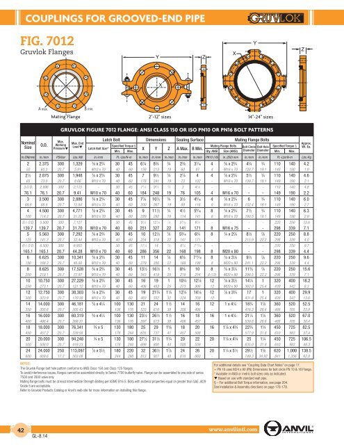
COUPLINGS FOR GROOVED-END PIPE<br />
FIG. 7012<br />
Gruvlok Flanges<br />
Mating Flange<br />
2"-12" sizes 14"-24" sizes<br />
Nominal<br />
Size<br />
O.D.<br />
GRUVLOK FIGURE 7012 FLANGE: ANSI CLASS 150 OR ISO PN10 OR PN16 BOLT PATTERNS<br />
Max.<br />
Working<br />
Pressure▼<br />
Max. End<br />
Load▼<br />
Latch Bolt Size*<br />
Latch Bolt Dimensions Sealing Surface Mating Flange Bolts<br />
Specified Torque §<br />
Mating Flange Bolts Bolt Circle Bolt Hole Specified Torque §<br />
X Y Z A Max. B Min.<br />
Min. Max. Qty. ANSI Size (ANSI) Diameter Diameter Min. Max.<br />
In./DN(mm) In./mm PSI/bar Lbs./kN In./mm Ft.-Lbs/N-m In./mm In./mm In./mm In./mm In./mm PN10 (16) in. (ISO) mm In./mm In./mm Ft.-Lbs/N-m Lbs./Kg<br />
2 2.375 300 1,329 3<br />
⁄8 x 2 3 ⁄4 30 45 6 1 ⁄4 8 3 ⁄8 3<br />
⁄4 2 3 ⁄8 3 7 ⁄16 4 5<br />
⁄8 x 2 3 ⁄4 4 3 ⁄4 3<br />
⁄4 110 140 4.2<br />
50 60.3 20.7 5.91 M10 x 70 40 60 159 213 19 60 87 4 M16 x 70 120.7 19.1 149 190 1.9<br />
2 1 ⁄2 2.875 300 1,948 3<br />
⁄8 x 2 3 ⁄4 30 45 7 9 1 ⁄2 3<br />
⁄4 2 7 ⁄8 4 4 5<br />
⁄8 x 2 3 ⁄4 5 1 ⁄2 3<br />
⁄4 110 140 4.6<br />
65 73.0 20.7 8.66 M10 x 70 40 60 178 241 19 73 102 - M16 x 70 139.7 19.1 149 190 2.1<br />
3 O.D. 2.996 300 2,115 - 30 45 7 1 ⁄4 9 3 ⁄4 3<br />
⁄4 3 4 1 ⁄8 - - - - 110 140 4.8<br />
76.1 76.1 20.7 9.41 M10 x 70 40 60 184 248 19 76 105 4 M16 x 70 - - 149 190 2.2<br />
3 3.500 300 2,886 3<br />
⁄8 x 2 3 ⁄4 30 45 7 7 ⁄8 10 1 ⁄2 3<br />
⁄4 3 1 ⁄2 4 9 ⁄16 4 5<br />
⁄8 x 2 3 ⁄4 6 3<br />
⁄4 110 140 6.0<br />
88.9 88.9 20.7 12.84 M10 x 70 40 60 200 267 19 89 116 8 M16 x 70 152.4 19.1 149 190 2.7<br />
4 4.500 300 4,771 3<br />
⁄8 x 2 3 ⁄4 30 45 9 11 1 ⁄2 3<br />
⁄4 4 1 ⁄2 5 9 ⁄16 8 5<br />
⁄8 x 2 3 ⁄4 7 1 ⁄2 3<br />
⁄4 110 140 6.3<br />
100 114.3 20.7 21.22 M10 x 70 40 60 229 292 19 114 141 8 M16 x 70 190.5 19.1 149 190 2.9<br />
5 1 ⁄2 O.D. 5.500 300 7,127 - 30 45 9 7 ⁄8 12 7 ⁄8 7<br />
⁄8 5 9 ⁄16 6 3 ⁄4 - - - - 220 250 15.6<br />
139.7 139.7 20.7 31.70 M10 x 70 40 60 251 327 22 141 171 8 M16 x 75 - - 298 339 7.1<br />
5 5.563 300 7,292 3<br />
⁄8 x 2 3 ⁄4 30 45 10 12 1 ⁄2 7<br />
⁄8 5 9 ⁄16 6 3 ⁄4 8 3<br />
⁄4 x 2 7 ⁄8 8 1 ⁄2 7<br />
⁄8 220 250 8.8<br />
125 141.3 20.7 32.44 M10 x 70 40 60 254 318 22 141 171 - - 215.9 22.2 298 339 4.0<br />
6 1 ⁄2 O.D. 6.500 300 9,955 - 30 45 11 1 ⁄4 14 7<br />
⁄8 6 5 ⁄8 7 13 ⁄16 - - - - 220 250 9.7<br />
165.1 165.1 20.7 44.28 M10 x 70 40 60 286 356 22 168 198 8 M20 x 80 - - 298 339 4.4<br />
6 6.625 300 10,341 3<br />
⁄8 x 2 3 ⁄4 30 45 11 14 7<br />
⁄8 6 5 ⁄8 7 13 ⁄16 8 3<br />
⁄4 x 3 1 ⁄8 9 1 ⁄2 7<br />
⁄8 220 250 9.6<br />
150 168.3 20.7 46.00 M10 x 70 40 60 279 356 22 168 198 8 M20 x 80 241.1 22.2 298 339 4.4<br />
8 8.625 300 17,528 3<br />
⁄8 x 2 3 ⁄4 30 45 13 1 ⁄2 16 1 ⁄2 1 8 5 ⁄8 10 8 3<br />
⁄4 x 3 1 ⁄4 11 3 ⁄4 7<br />
⁄8 220 250 15.6<br />
200 219.1 20.7 77.97 M10 x 70 40 60 343 419 25 219 254 8 (12) M20 x 80 298.5 22.2 298 339 7.1<br />
10 10.750 300 27,229 3<br />
⁄8 x 2 3 ⁄4 30 45 16 19 1 10 3 ⁄4 12 1 ⁄8 12 7<br />
⁄8 x 3 1 ⁄2 14 1 ⁄4 1 320 400 18.2<br />
250 273.1 20.7 121.12 M10 x 70 40 60 406 483 25 273 308 12 M20 x 90 362.0 25.4 439 542 8.3<br />
12 12.750 300 38,303 3<br />
⁄8 x 2 3 ⁄4 30 45 19 21 3 ⁄4 1 1 ⁄4 12 3 ⁄4 14 1 ⁄8 12 7<br />
⁄8 x 3 3 ⁄4 17 1 320 400 29.9<br />
300 323.9 20.7 170.38 M10 x 70 40 60 483 552 32 324 359 12 - 431.8 25.4 439 542 13.6<br />
14 14.000 300 46,181 5<br />
⁄8 x 4 1 ⁄4 100 130 21 24 1 1 ⁄2 14 16 12 1 x 4 1 ⁄4 18 3 ⁄4 1 1 ⁄8 360 520 52.5<br />
350 355.6 20.7 205.43 - 136 176 533 610 38 356 406 - - 476.3 28.6 488 705 23.8<br />
16 16.000 300 60,319 5<br />
⁄8 x 4 1 ⁄4 100 130 23 1 ⁄2 26 1 ⁄2 1 1 ⁄2 16 18 16 1 x 4 1 ⁄4 21 1 ⁄4 1 1 ⁄8 360 520 67.0<br />
400 406.4 20.7 268.31 - 136 176 597 673 38 406 457 - - 539.8 28.6 488 705 30.4<br />
18 18.000 300 76,341 3<br />
⁄4 x 5 130 180 25 29 1 5 ⁄8 18 20 16 1 1 ⁄8 x 4 3 ⁄4 22 3 ⁄4 1 1 ⁄4 450 725 82.5<br />
450 457.2 20.7 339.58 - 176 244 635 737 41 457 508 - – 577.9 31.8 610 983 37.4<br />
20 20.000 300 94,248 3<br />
⁄4 x 5 130 180 27 1 ⁄2 31 1 ⁄2 1 3 ⁄4 20 22 20 1 1 ⁄8 x 4 3 ⁄4 25 1 1 ⁄4 450 725 106.5<br />
500 508.0 20.7 419.23 - 176 244 699 800 44 508 559 - – 635.0 31.8 610 983 48.3<br />
24 24.000 250 113,097 7<br />
⁄8 x 5 1 ⁄2 180 220 32 36 1 ⁄2 1 7 ⁄8 24 26 20 1 1 ⁄4 x 5 1 ⁄2 29 1 ⁄2 1 3 ⁄8 620 1,000 138.5<br />
600 609.6 17.2 503.08 - 244 298 813 927 48 610 660 - - 749.3 34.92 841 1,356 62.8<br />
NOTES:<br />
The Gruvlok Flange bolt hole pattern conforms to ANSI Class 150 and Class 125 flanges.<br />
To avoid interference issues, flanges cannot be assembled directly to Series 7700 butterfly valve. Flange can be assembled to one side of series<br />
7500 and 7600 valve only.<br />
Mating flange bolts must be at least Intermediate Strength Bolting per ASME B16.5. Bolts with material properties equal or greater than SAE J429<br />
Grade 5 are acceptable.<br />
Refer to Gruvlok Products Catalog or Anvil’s web site for more information on installing this flange.<br />
Approx.<br />
Wt. Ea.<br />
For additional details see “Coupling Data Chart Notes” on page 17.<br />
+ PN 16 uses M24 x 90 (PN) Dimensions for bolt circle PN 10 & 16 Flange.<br />
* Available in ANSI or metric bolt sizes only as indicated.<br />
t Based on use with standard wall pipe.<br />
§ – For additional Bolt Torque information, see page 204.<br />
See Installation & Assembly directions on page 176-178.<br />
42<br />
GL-8.14<br />
www.anvilintl.com