for Explosive Atmosphere
for Explosive Atmosphere
for Explosive Atmosphere
- No tags were found...

Create successful ePaper yourself
Turn your PDF publications into a flip-book with our unique Google optimized e-Paper software.
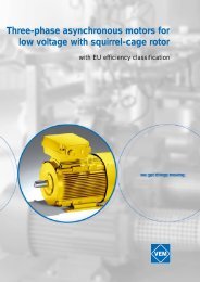
Three-phase<br />
asynchronous motors<br />
with squirrel-cage rotor<br />
<strong>for</strong> potentially<br />
explosive atmospheres<br />
VEM motors GmbH
Table of contents<br />
Page<br />
Technical explications<br />
Motors in the increased safety type of protection EEx e 1<br />
Motors in the flame-proof enclosure type of protection EEx d 1<br />
Motors in the non-sparking type of protection Ex nA 1<br />
Motors <strong>for</strong> being used in case of potentially inflammable dusts (zone 21, 22)2<br />
EC certificates of con<strong>for</strong>mity and EC certificates of sample test 2 - 4<br />
Standards and specifications 5<br />
Tolerances 6<br />
Tolerances of the design values 6<br />
Tolerances of the fixing dimensions 6<br />
Mechanical design<br />
Types of construction 7<br />
Shaft ends 8<br />
Degrees of protection 8<br />
Sense of rotation 8<br />
Bearing arrangement / bearing lubrication 8<br />
Application of cylinder roller bearings 8<br />
Transport locking 8<br />
Vibration behaviour 8<br />
Noise characteristics 9<br />
Cooling and ventilation 9<br />
Paint coat 9<br />
Electrical design<br />
Design voltage and frequency 9<br />
Design torque 9<br />
Design output 10<br />
Additional thermal winding protection 10<br />
Overload capacity 10<br />
Design efficiency and power factor 10<br />
Restarting in case of residual field and phase opposition 10<br />
Project planning and user instructions<br />
Hazardous areas 10<br />
Installation and electric connection 11<br />
Protective measures against inadmissible temperature rise 11<br />
Maintenance and repair 11<br />
Spare parts 11<br />
Selection data<br />
Increased safety type of protection EEx e II<br />
Electrical selection data 12 - 23<br />
Dimensions 24 - 25<br />
Bearing 26<br />
Terminal boxes 27<br />
Flameproof enclosure type of protection EEx d II / EEx de II<br />
Electrical selection data 28 - 31<br />
Dimensions 32 - 33<br />
Bearing 34<br />
Terminal boxes 35<br />
Non-sparking type of protection Ex nA II<br />
Electrical selection data 36 - 39<br />
Dimensions, see data <strong>for</strong> zone 21 Ex II 2D<br />
Bearing, see data <strong>for</strong> zone 21 Ex II 2D<br />
Terminal boxes, see data <strong>for</strong> zone 21 Ex II 2D<br />
Motors <strong>for</strong> being used in case of potentially inflammable dusts, zone 21; Ex II 2D<br />
Electrical selection data 40 - 43<br />
Dimensions 44 - 45<br />
Bearing arrangement 46<br />
Terminal boxes 47<br />
Motors <strong>for</strong> being used in case of potentially inflammable dusts, zone 22; Ex II 3D<br />
Electrical selection data 48 - 51<br />
Dimensions 52 - 53<br />
Bearing 54<br />
Terminal boxes 55<br />
Marketing / Delivery program 56<br />
Reservation of modifications: Subject to modifications of output, technical data, dimensions and weights specified in the list.<br />
The illustrations are not binding.
Technical explications<br />
Squirrel-cage motors, increased safety type of protection „e“<br />
Constructive version<br />
Series<br />
K11R / KPER / K12R<br />
Sizes 63 - 355<br />
Degrees of protection IP 54, IP 55, IP 56, IP 65 according to DIN VDE 0530-5: 1988<br />
Type of cooling IC 411 according to DIN EN 60034-6: 1996<br />
Types of construction IM B3, IM B35, IM B5 and derived types of construction according to DIN EN 60034-7: 1996<br />
When mounting motors with vertical shaft position, there is to be prevented the ingress of <strong>for</strong>eign bodies into the vent holes.<br />
Design <strong>for</strong> potentially explosive atmospheres according to apparatus group II, category 2 acc. to<br />
DIN EN 50 014:1994 (DIN VDE 0170/0171 part 1) General Provisions<br />
DIN EN 50 019:1996 (DIN VDE 0170/0171 part 6) Increased Safety „e“<br />
Temperature class T1 to T3<br />
Fixing dimensions and coordination between output and dimensions according to DIN 42673 page 2 or DIN 42677 page 2<br />
Ambient temperatures -40°C to +40°C<br />
The construction of the motors is tested through the Physikalisch-Technische Bundesanstalt (PTB) Braunschweig and approved with the following<br />
partial certificates:<br />
Partial certificate PTB no. Ex-95.D.3020 U with the respective supplements<br />
Partial certificate PTB no. Ex-95.D.3162 U with the respective supplement<br />
Partial certificate PTB no. Ex-95.D.3021 U with the respective supplements<br />
Partial certificate PTB no. Ex-93.C.3059 U with the respective supplements<br />
Partial certificate PTB no. Ex-90.C.3152 U with the respective supplements.<br />
Furthermore, the series are tested through the Schweizerischer Elektrotechnischer Verein<br />
certificate A. no. 97.1 10387.01<br />
and approved through the Schweizer Eidgenössische Starkstrominspektorat (Swiss Confederate Power Current Inspectorate)<br />
approval no. 98.5 51477.01, 95.1 11107.07.<br />
The reports on the test <strong>for</strong> intended use in hazardous areas are available. The certificates of con<strong>for</strong>mity and the EC certificates of sample test<br />
issued <strong>for</strong> the individual types are to be taken from the approval summary.<br />
Squirrel-cage motors, flame-proof enclosure type of protection EEx de/d<br />
Series<br />
K81R / K82R<br />
Sizes 56 - 355<br />
Degrees of protection IP 54, IP 55, IP 56 according to DIN VDE 0530-5: 1988<br />
Type of cooling IC 411 according to DIN EN 60034-6: 1996<br />
Types of construction IM B3, IM B35, IM B5 and derived types of construction according to DIN EN 60034-7: 1996<br />
When mounting motors with vertical shaft position, there is to be prevented the ingress of <strong>for</strong>eign bodies into the vent holes.<br />
Design <strong>for</strong> potentially explosive atmospheres according to apparatus group II, category 2 acc. to<br />
DIN EN 50 014:1994 (DIN VDE 0170/0171 part 1) General Provisions<br />
DIN EN 50 018:1994 (DIN VDE 0170/0171 part 5) Flame Proof Enclosure Type of Protection „d“<br />
Temperature class T3 to T6<br />
Fixing dimensions and coordination between output and dimensions according to DIN 42673 page 3 or DIN 42677 page 3<br />
Ambient temperatures -20°C to +60°C<br />
The construction of the motors is tested through the Physikalisch-Technische Bundesanstalt (PTB) Braunschweig and approved with the following<br />
EC certificates of sample test:<br />
Partial certificate PTB no. PTB 99 ATEX 1098, EExdIICT3 - T6, EEx de T3 - T6<br />
Squirrel-cage motors, type of protection „n“ according to IEC report 79-15 (1987)<br />
Series<br />
K11R / KPER / K12R<br />
Size 63 - 355<br />
Degrees of protection IP 54, IP 55, IP 56, IP 65 according to DIN VDE 0530-5: 1988<br />
Type of cooling IC 411 according to DIN EN 60034-6: 1996<br />
1
Fixing dimensions and coordination between output and dimensions according to DIN 42673 page 1 or DIN 42677 page 1<br />
Types of construction IM B3, IM B35, IM B5 and derived types of construction according to DIN EN 60034-7: 1996<br />
When mounting motors with vertical shaft position, there is to be prevented the ingress of <strong>for</strong>eign bodies into the vent holes.<br />
Design <strong>for</strong> potentially explosive atmospheres according to apparatus group II, category 3 acc. to IEC report 79-15 (1987)<br />
Temperature class T3 or T4<br />
Ambient temperatures -40°C to +55°C<br />
For K11R are available the EC certificates of sample test IBExU994TEX 1094 and 1095, <strong>for</strong> KPER are available the EC certificates of sample test<br />
PTB no. Ex-.96.Y.3725U, EX-96.Y.3726.<br />
Furthermore, the series are tested through the Schweizerischer Elektrotechnischer Verein and approved through the Schweizer Eidgenössisches<br />
Starkstrominspektorat (Swiss Confederate Power Current Inspectorate)<br />
Certificate A. no. 95.1 11108.03<br />
Approval no. 95.1 11108.04.<br />
Squirrel-cage motors <strong>for</strong> being used in case of potentially inflammable dusts (zone 21, 22)<br />
Design <strong>for</strong> zone 21<br />
Series<br />
KPER / K11Q<br />
Sizes<br />
56 - 280 (315 in preparation)<br />
Degree of protection IP 65 according to DIN VDE 0530-5: 1988<br />
Type of cooling IC 411 according to DIN EN 60034-6: 1996<br />
Types of construction IM B3, IM B35, IM B5 and derived types of construction according to DIN EN 60034-7: 1996<br />
When mounting motors with vertical shaft position, there is to be prevented the ingress of <strong>for</strong>eign bodies into the vent holes.<br />
Design <strong>for</strong> potentially explosive atmospheres according to apparatus group II, category 2 acc. to DIN EN 50281-1-1 and -2<br />
Fixing dimensions and coordination between output and dimensions according to DIN 42673 page 1 or DIN 42677 page 1<br />
Ambient temperatures -40°C to +40°C<br />
The design of the motors has been tested by the DMT (Deutsche Montan Technik), certified with the certificate<br />
DMT 00 ATEX E 002 X <strong>for</strong> the sizes 132 to 280<br />
DMT 00 ATEX E 012 X <strong>for</strong> the sizes 56 to 132 T<br />
and approved in the respective test report.<br />
Design <strong>for</strong> zone 22<br />
Series<br />
K21R / K11R<br />
Sizes 56 - 355<br />
Degrees of protection IP 55 according to DIN VDE 0530-5: 1988<br />
Type of cooling IC 411 according to DIN EN 60034-6: 1996<br />
Types of construction IM B3, IM B35, IM B5 and derived types of construction according to DIN EN 60034-7: 1996<br />
When mounting motors with vertical shaft position, there is to be prevented the ingress of <strong>for</strong>eign bodies into the vent holes.<br />
Design <strong>for</strong> potentially explosive atmospheres according to apparatus group II, category 3 acc. to E DIN EN 50281-1-1 and -2<br />
Fixing dimensions and coordination between output and dimensions according to DIN 42673 page 1 or DIN 42677 page 1<br />
Ambient temperatures -40°C to +40°C<br />
The design of the motors has been certified with manufacturer’s declaration of incorporation.<br />
EC certificates of con<strong>for</strong>mity and EC certificates of prototype test<br />
2
3
4
Standards and specifications<br />
The motors correspond to the appropriate standards, in particular to the following::<br />
Title DIN/VDE IEC<br />
General regulations DIN EN 60034-1/02.99 IEC 34-1<br />
<strong>for</strong> electrical rotating machines IEC 85<br />
Fixing dimensions and coordination between DIN 42673 (IEC 72)<br />
output and dimensions at IM B3<br />
Fixing dimensions and coordination between output DIN 42677 (IEC 72)<br />
and dimensions at IM B5, IM B35 and IM B14<br />
Rotating electrical machines, terminal markings and direction of rotation DIN VDE 0530 part 8 IEC 34-8<br />
Rotating electrical machines, symbols DIN EN 60034-7 IEC 34-7<br />
<strong>for</strong> types of construction and mounting<br />
Rotating electrical machines, built-in thermal protection - IEC 34-11<br />
Rotating electrical machines, methods of cooling DIN EN 60034-6 IEC 34-6<br />
Rotating electrical machines, classification DIN VDE 0530 part 5 IEC 34-5<br />
of degrees of protection<br />
Rotating electrical machines, mechanical vibrations of DIN EN 60034-14 IEC 34-14<br />
certain machines with shaft heights 56 mm and higher<br />
Cylindrical shaft ends <strong>for</strong> rotating electrical machines DIN 748 part 3 IEC 72<br />
Rotating electrical machines, noise limits DIN EN 60034-9 IEC 34-9<br />
Rotating electrical machines, starting per<strong>for</strong>mance of single-speed DIN EN 60034-12 IEC 34-12<br />
three-phase cage induction motors <strong>for</strong> voltages up to 660 V, 50 cps<br />
IEC-standard voltages DIN IEC 38 IEC 38<br />
For EEx-motors are valid furthermore<br />
General regulations DIN EN 50014/VDE 0170/0171 T.1 IEC 79-0<br />
Increased safety „e“ DIN EN 50019/VDE 0170/0171 T.6 IEC 79-7<br />
Flameproof enclosure „d“ DIN EN 50018 / VDE 0170/0171 T.5 -<br />
Electrical apparatus <strong>for</strong> being used in areas DIN EN 50281-1-1 -<br />
with potentially inflammable dusts<br />
Furthermore, VEM motors comply with various <strong>for</strong>eign regulations which have been adapted to the IEC-publ. 34-1 and they are available<br />
according to the regulations of the Classification Authorities<br />
Germanischer Lloyd<br />
Bureau Veritas<br />
Lloyd’s Register of Shipping<br />
American Bureau of Shipping<br />
Det Norske Veritas<br />
Russian Register.<br />
For these standards and specifications are valid the following admissible limits of temperature rise:<br />
Specifications Coolant temperature Admissible limit of temperature rise in K<br />
(measuring acc. to resistance method)<br />
Insulation class<br />
°C A E B F<br />
DIN VDE 60034-1/02.99 40 60 75 80 105<br />
IEC 34-1 40 60 75 80 105<br />
Switzerland SEV 40 60 75 80 105<br />
Germanischer Lloyd 45 55 70 75 95<br />
American Bureau of Shipping 50 55 65 75 95<br />
Bureau Veritas 50 50 65 70 90<br />
Det Norske Veritas 45 50 65 70 90 1)<br />
Lloyd’s Register 45 50 65 70 90<br />
Russ. Register 40/45 60 75 85 110<br />
1) only with special approval<br />
5
Tolerances<br />
Following tolerances are admitted according to DIN EN 60034-1/02.99. These tolerances are permissible <strong>for</strong> the values assured <strong>for</strong> three-phase asynchronous<br />
motors, taking the necessary manufacturing tolerances and material variations of the used raw materials into account. The standard contains<br />
the following notes to that:<br />
1. A guarantee <strong>for</strong> all or any of the values shown in the table ist not mandatory. In tenders, the guaranteed values <strong>for</strong> which permissible deviations<br />
should apply must be expressly specified. The permissible variations must correspond to those stated in the table.<br />
2. There is pointed to the distinctions concerning the definition „Guarantee“. In some countries, distinction is drawn between guaranteed values and<br />
typical or declared values.<br />
3. If the permissible deviation applies only in one direction, then the value in other direction is not limited.<br />
Tolerances of the design values<br />
Efficiency (with indirect calculation)<br />
-0,15 (1-h) up to PN ≤ 50 kW<br />
-0,1 (1-η) up to P N > 50 kW<br />
Power faktor 1-cosϕ at least 0,02<br />
6 at most 0,07<br />
Slip<br />
+ 20 % up to P N ≥ 1kW<br />
(at rated-load operating temperature)<br />
+ 30 % up to P N < 1kW<br />
Starting current + 20 %<br />
(in the planned starting circuit)<br />
without limiting downwards<br />
Starting torque - 15 % and + 25 %<br />
Pull-up torque - 15 %<br />
Pull-out torque - 10 % (with the application of this tolerance M K /M at least. 1,6)<br />
Moment of inertia + 10 %<br />
Noise intensity (measurement area sound pressure level) + 3 dB (A)<br />
Tolerances of the fixing dimensions<br />
Dimensional<br />
short sign according to DIN Meaning of the dimension Fit or tolerance<br />
a Spacing of housing foot fixing holes in axial direction + 1 mm<br />
b Spacing of housing foot fixing holes + 1 mm<br />
across the axial direction<br />
e1 Pitch circle diameter of the attachment flange + 0,8 mm<br />
a1 Diameter or width across corner of the flange + 1 %<br />
g Largest width of the motor + 2 %<br />
f<br />
(without terminal box)<br />
k Overall length of the motor + 1 %<br />
k1<br />
p Overall height + 2 %<br />
(lower edge foot, housing or flange up to highest point of the motor)<br />
s Diameter of the fixing holes of the foot or of the flange + 3 %<br />
s1<br />
w1 Centre of the first fixing hole up to shaft end shoulder + 3 mm<br />
w2<br />
b1 Diameter of the centering shoulder of the attachment flange up to 230 j6<br />
from 250 h6<br />
d Diameter of the shaft end up to Ø 48 k6<br />
d1<br />
from Ø 55 m6<br />
h Shaft height (lower edge foot up to centre of shaft end) up to 250-0,5<br />
higher than 250-1<br />
u Width of the key h9<br />
u1<br />
t Lower edge of shaft end up to upper edge of key + 0,2 mm<br />
t1<br />
Motor weight - 5 bis + 10 %<br />
6
Mechanical design<br />
Types of construction<br />
Basic types of construction can be used in all derived types of construction.<br />
Exceptions:<br />
1) On inquiry<br />
2) Only available in the types of construction 56 - 160<br />
3) This type of construction is to be ordered directly because of additional water return hole in the flange end shield<br />
7
Shaft ends<br />
As specified in IEC 34-7, the definition of the motor ends is as follows :<br />
D-end (DS): Drive end of the motor (Driving side)<br />
N-end (NS): Non-driving end (opposite end to the drive end) (Non-driving side)<br />
The motors are always supplied with the key fitted. The second shaft end can transmit the full nominal output with coupling service. The power transmission<br />
capability at belt service, chain service or pinion service <strong>for</strong> the second shaft end is available on request.<br />
Degrees of protection<br />
Degrees of protection <strong>for</strong> electrical machines are indicated according to DIN VDE 0530 part 5 through the identification marking „IP“ and two characteristic<br />
numerals <strong>for</strong> the degree of protection. The first characteristic numeral specifies the protection against damaging ingress of dust and <strong>for</strong>eign<br />
particles and against contact with inner moving or live parts, the second characteristic numeral specifies the protection against the penetration<br />
of water having an effect on the machine from different directions and with different intensities.<br />
The respective degrees of protection of the various series of motors are to be taken from the tables of the electrical selection data.<br />
Sense of rotation<br />
When connecting a VEM motor with the stator terminals U, V, W to a three-phase mains with the phase sequence L1, L2 and L3, the direction of rotation<br />
of the motor goes clockwise as seen on the D-end. In case of required alteration of the direction of rotation, two terminals are to be exchanged.<br />
Bearing arrangement / bearing lubrication<br />
VEM motors are equipped with antifriction bearings of well-known manufacturers. The bearings have a nominal service life of at least 20.000 hours<br />
<strong>for</strong> maximum permissible load conditions. For motors without additional axial loading, the nominal service life is 40.000 hours <strong>for</strong> coupling service.<br />
The sizes 56 - 160 are equipped with life-lubricated bearings. For motors from size 180, depending on the useful life of grease, bearings must be<br />
relubricated in good time so that the nominal bearing service life is reached. Under normal operating conditions, the grease packing will last <strong>for</strong><br />
10.000 hours of operation with 2-pole version and <strong>for</strong> 20.000 hours of operation with versions from 4 poles upwards without being renewed. For<br />
motors fitted with relubricating facility and working under normal operating conditions, the grease will last <strong>for</strong> 2.000 hours of operation or <strong>for</strong> 4.000<br />
hours of operation. The standard grease is a KE2R-40 type according to DIN 51825.<br />
Use of cylindrical roller bearings<br />
Using cylindrical roller bearings („heavy bearing arrangement“), relatively high radial <strong>for</strong>ces or masses can be supported at the motor shaft end.<br />
Examples : belt drives, pinions or heavy couplings. The minimum radial <strong>for</strong>ce at the shaft end must be a quarter of the permissible radial <strong>for</strong>ce.<br />
Account must be taken of permissible shaft end loading.<br />
Important to note: Radial <strong>for</strong>ces below the minimum value can lead to bearing damages within a few hours. Test runs in no-load state are only<br />
permissible <strong>for</strong> a short period.<br />
If the specified minimum radial <strong>for</strong>ces cannot be met, we recommend to use grooved ball bearings („easy bearing arrangement“). Bearing change<br />
is possible on request.<br />
Transport locking<br />
According to the specific conditions of transport, motors with cylindrical roller bearing can be provided, according to DIN 5412, with a transport locking<br />
on the driving end as protection against transport shocks.<br />
Vibration characteristics<br />
The admissible vibration intensities of electric motors are specified in DIN EN 60034-14.<br />
The vibration intensity stage N (normal) is achieved or is below limit by VEM motors in the basic version. On demand, the vibration intensity stages<br />
R (reduced) and S (special) can be delivered in dependence on the type at extra charge.<br />
The following values are recommended according to DIN EN 60034-14:<br />
Vibration intensity Speed range Limit values of vibration velocity (mm/s)<br />
stages rpm in frequency range 10 to 1000 cps <strong>for</strong> sizes<br />
56 - 132 160 - 225 250 - 450<br />
N 600-3600 1,8 2,8 3,5<br />
(normal)<br />
R 600-1800 0,71 1,12 1,8<br />
(reduced) up to 1800-3600 1,12 1,8 2,8<br />
S 600-1800 0,45 0,71 1,12<br />
(special) up to 1800-3600 0,71 1,12 1,8<br />
8
All rotors are dynamically balanced with half key inserted. This balancing is documented on the rating plate with the letter H after the motor number.<br />
On inquiry, the balancing is possible with the complete key; this balancing is documented with the letter F after the motor number.<br />
Noise characteristics<br />
The noise measurement is carried out according to DIN EN 23741/23742 at design output, design voltage and design frequency. In accordance with<br />
DIN EN 60034-9, the spatial mean value of the measurement area sound pressure level LpA measured at a distance of 1 m from the machine outline<br />
is stated as noise intensity in dB (A).<br />
The tabular value + 5 dB (A) applies as an approximate value <strong>for</strong> motors in 60 cps design. Binding data <strong>for</strong> 60 cps are available on request. For the<br />
main type series, the noise values are specified in the main catalogue in <strong>for</strong>m of tables. In case of special versions, please refer to the manufacturer.<br />
Cooling and ventilation<br />
The motors are equipped with radial fans which cool the motor, whatever is the direction of rotation (IC 411 according to DIN EN 60034-6). When<br />
installing the motors, care should be taken that a minmum distance from the fan cover to the wall (dimension B) is maintained.<br />
Paint finish<br />
Normal finish<br />
Adapted <strong>for</strong> group of climates „moderate“ according to IEC 721-2-1,<br />
• weatherprotected and non-weatherprotected locations, short time up to 100 % of relative air humidity at temperatures up to + 30 °C,<br />
continuously up to 85 % of relative air humidity at up to + 25 °C.<br />
Finish system Sizes 56 - 112<br />
All components except aluminium terminal boxes : prime plastic paint, layer thickness approx. 30µm<br />
Finish coat water-soluble varnish with layer thicknesses from 30 µm to 60 µm<br />
Sizes 132 - 355<br />
Synthetic-resin zincphosphate primary coat, layer thickness approx. 30 µm<br />
Finish coat : two-component polyurethane, layer thickness approx. 30 µm<br />
Special finish<br />
Adapted <strong>for</strong> group of climates „World-wide“ according to IEC 721-2-1<br />
• Non-weather-protected location in corrosive chemical and sea atmosphere, short time up to 100 % of relative air humidity at temperatures<br />
up to + 35 °C, continuously up to 98 % of relative air humidity with temperatures up to + 30 °C<br />
Finish system<br />
Sizes 56 - 112<br />
All components with prime plastic paint, layer thicknesses: approx. 30 µm<br />
Finish coat water-soluble varnish with layer thicknesses from 60 µm to 90 µm<br />
Two-component coating varnish on demand<br />
BG 132 - 355<br />
Synthetic-resin zincphosphate primary coat, layer thickness approx. 30 µm<br />
Intermediate coat on two-component base, layer thickness approx. 30 µm<br />
Finish coat: two-component coating varnish on demand<br />
Standard colour RAL 7031 blue-grey<br />
Further special coating systems:<br />
Version <strong>for</strong> excessive thermal stresses<br />
Version <strong>for</strong> excessive chemical and radiation stresses<br />
Special finish upon customer’s request<br />
Design voltage and frequency<br />
In the basic version, the motors are supplied <strong>for</strong> following design voltages:<br />
230/400 V ∆/Y 50 cps 690 V ∆ 50 cps<br />
400/690 V ∆/Y 50 cps 480 V ∆ 60 cps<br />
The motors can run without changing the nominal output in mains, in which the voltage at nominal frequency deviates from the nomianl value up to<br />
± 5 % (design voltage range A). The above mentioned standard voltages according to DIN IEC 38 are taken as design point. Application <strong>for</strong> voltage<br />
range is possible, limits see tables of the electrical selection data.<br />
Special voltages and frequencies upon customer’s request.<br />
Design torque<br />
The nominal torque in Nm given at the motor shaft is calculated by<br />
M = 9550 x P<br />
n<br />
with P = nominal output in kW<br />
n = speed in rpm<br />
9
If the voltages deviate from their nominal value (within the admissible limits), starting torque, pull-up torque and pull-out torque change about quadratically<br />
and the starting current changes about linearly with the voltage variation.<br />
Design output<br />
The nominal output applies <strong>for</strong> continuous operation as specified in DIN EN 60034-1/02.99 at a coolant temperature of 40 °C and a site altitude of<br />
≤ 1000 m above M.S.L. On account of the thermal reserve, the nominal output can be maintained up to 50 °C coolant temperature or up to 2.500 m<br />
site altitude. These conditions can only be applied alternatively. The output must be reduced in case of coupling. In case of motors in design <strong>for</strong> seagoing<br />
vessels, the output is possibly reduced according to the Classification Rules.<br />
Additional thermal winding protection<br />
The additional thermal winding protection is exclusively provided as additional protective device <strong>for</strong> monitoring the temperature of the stator winding<br />
and is not regarded as protective device according to VDE 0170/0171 part 6 / DIN EN 50019 appendix A.<br />
Overload capacity<br />
In compliance with DIN EN 60034-1, all motors can be exposed to the following overload conditions:<br />
- 1,5 times the rated current <strong>for</strong> 2 min.<br />
- 1,6 times the rated torque <strong>for</strong> 15 s<br />
Both conditions apply to design voltage and design frequency.<br />
Design efficiency and design power factor<br />
The efficiency η and the power factor cos ϕ are stated in the Motor Selection Data lists. Partial load ratings on demand.<br />
Re-starting with residual field and phase opposition<br />
A re-starting after mains failure against 100 % residual field is possible <strong>for</strong> all motors.<br />
Project planning and application instructions<br />
Hazardous areas<br />
Which zones in the open or in closed areas are to be considered hazardous within the relevant rules or regulations is to be leaved exclusively to the<br />
user or, in case of doubt about the definition of harzardous areas, to the competent inspectorate.<br />
Electrical motors <strong>for</strong> potentially explosive atmospheres correspond to the standards of the series DIN EN 60034 (VDE 0530) as well as DIN EN 50014-<br />
50020, DIN EN 50281-1-1. In hazardous areas they can only be placed in accordance with the competent inspectorate being responsible <strong>for</strong> the<br />
assignment of potentially explosive atmospheres (zonal classification). The type of protection, the temperature class as well as special requirements<br />
are indicated on the rating plate or in the certificate of con<strong>for</strong>mity.<br />
Apparatus group I, category M2<br />
Under this category come electrical machines of increased-safety types protections, of flameproof enclosure types of protection, of pressurized enclosure<br />
types of protection <strong>for</strong> being used in the mining area.<br />
Apparatus group II, category 2 (up to now zone 1)<br />
Under this category come electrical machines of increased-safety types protections, of flameproof enclosure types of protection, of pressurized enclosure<br />
types of protection <strong>for</strong> being used in the other areas endangered through an explosive atmosphere.<br />
Apparatus group II, category 3 (up to now zone 2)<br />
Under this category come electrical machines of the type of protection „Ex n“.<br />
If the certificate number is completed by the letter X, special requirements in the certificate of con<strong>for</strong>mity are to be observed.<br />
The operation at the converter must be certified specially. The special manufacturer’s instructions are to be observed absolutely. For the type of protection<br />
EEx e, motor, converter and protective device must be marked as components belonging together and the admissible operating data must<br />
be determined in the common test certificate (VDE 0165).<br />
Through the interconnecting cable installed between converter and electrical machine, the voltage peaks generated by the converter can be badly<br />
influenced in their magnitude. In the system converter - cable - electrical machine, the maximum value of the voltage peaks at the terminals of the<br />
machine must never exceed the value indicated in the special manufacturer’s instructions.<br />
10
Installation and electric connection<br />
The erection of electrical installations in potentially explosive atmospheres requires in Germany the observance of the following regulations:<br />
- DIN VDE 0118 „Erection of Electrical Installations in Mines“.<br />
- ElBergV „Elektrobergverordnung“<br />
(Ordinance Regulating the Electrical Installations in Mines).<br />
- DIN 56 165/VDE 0165/DIN EN 60079-14 „Installation of Electrical Apparatus in Hazardous Areas.<br />
-VbF<br />
„Verordnung über brennbare Flüssigkeiten“<br />
(Ordinance Concerning Flammable Liquids)<br />
Abroad are to be followed the corresponding national regulations.<br />
The general safety and commissioning instructions are valid <strong>for</strong> the electric connection. The cable entries must be approved <strong>for</strong> the explosion-proof<br />
area and they must be protected against selfloosening. Non-used apertures are to be closed with accepted plugs.<br />
Protective measures against excessive temperature rise<br />
If the test certificate or the rating plate do not contain different data concerning duty type and tolerances, the electrical machines are designed <strong>for</strong><br />
continuous duty and <strong>for</strong> normal starts, not recuring frequently, in the course of which the temperatures are not rising essentially. The motors can only<br />
be used <strong>for</strong> that duty being indicated on the rating plate.<br />
The range A in DIN EN 60034-1 (VDE 0530, part 1) - voltage ± 5 %, frequency ± 2 %, wave<strong>for</strong>m, supply balance - is to be observed so that the temperature<br />
rises within the admissible limits. Greater deviations from the design values can cause an excessive temperature rise of the electric machine<br />
and must be indicated on the rating plate.<br />
Each machine is to be protected in all phases against excessive temperature rise by means of an inverse time-delay circuit breaker with phase-failure<br />
protection according to VDE 0660 or an equivalent device. The protective device is to be set to the design current. In case of windings in delta<br />
connection, the trip elements are connected in series with phase windings and set to 0,58 times the design current. When being impossible this<br />
connection, additional protective measures are necessary (eg. thermal machine protection).<br />
In contrast to the degree of protection „Ex-n“, in case of the „increased safety“ the start will be monitored too. There<strong>for</strong>e, in case of locked rotor, the<br />
protective device must disconnect within the t E -time indicated <strong>for</strong> the corresponding temperature class. The requirement is fulfilled if the tripping time<br />
- it is to be taken from the tripping characteristic (initial temperature of 20 °C) <strong>for</strong> the ratio I A /I N - doesn’t exceed the indicated t E -time.<br />
In compliance with the data of the certificate of con<strong>for</strong>mity, electrical machines <strong>for</strong> heavy starting (acceleration time > 1,7 x t E -time) are to be protected<br />
through a starting-cycle monitoring circuit.<br />
Thermal machine protection through direct temperature monitoring of the winding is admissible if that is certified and indicated on the rating plate. It<br />
is consisting of temperature sensors according to DIN 44081 / 44082 which in connection with tripping units, provided with the mark of con<strong>for</strong>mity<br />
of an authorized testing agency, are guaranteeing the explosion-protection.<br />
In case of pole-changing motors, seperate interlocked protective devices are necessary <strong>for</strong> each speed step. We recommend devices provided with<br />
the test report of an authorized testing agency.<br />
Maintenance and repair<br />
In Germany, maintenance, repair and modifications at explosion protected machines are to be carried out observing the ElexV/ElBergV, the safety<br />
instructions und descriptions of the general maintenance instructions.<br />
Work, influencing the explosion protection, such as eg.:<br />
- repair work at the stator or rotor winding and at the terminals,<br />
- repair work at the ventilation system,<br />
- the disassembly of explosion-proof machines,<br />
are to be carried out at the manufacturer or through a workshop specialized <strong>for</strong> electrical machines.<br />
The work is to be marked by an additional repair name plate with the following data:<br />
- date<br />
- operative firm<br />
- if necessary, mode of repair<br />
- if necessary, sign of the expert.<br />
If the work will not be realized by part of the manufacturer, it is to be accepted by an officially recognized expert who has to issue a written confirmation<br />
or to provide the machine with his mark of con<strong>for</strong>mity. Abroad are to be observed the corresponding national regulations.<br />
Spare parts<br />
There may only be used original spare parts (see list of spare parts), excepting standardized, commercial and equivalent parts (eg. antifriction bearings);<br />
in particular, this applies to seals and connecting pieces too.<br />
11
Motor selection data<br />
Design point 400 V, 50 cps, EEx e<br />
Three-phase motors with squirrel-cage rotor<br />
Increased-safety type of protection EEx e II according to DIN EN 50014/50019<br />
<strong>for</strong> design voltage, temperature classes T1, T2 and T3<br />
with surface cooling, duty type S1, continuous duty<br />
insulation class F, degree of protection IP 54, 50 cps<br />
Type P Tempe- n η cos ϕ I I A /I N M A /M N M S /M N M K /M N t E -time J m<br />
rature 400 V T3 T1,T2<br />
kW class rpm % - A s s kgm 2 kg<br />
Synchronous speed 3000 rpm - 2-pole design<br />
KPER 63 K2 0,18 T1-T3 2870 61,0 0,80 0,53 3,7 1,6 1,6 2,0 29 30 0,00013 4,9<br />
KPER 63 G2 0,25 T1-T3 2800 65,0 0,74 0,75 4,1 1,9 1,9 2,2 13 15 0,00015 5,2<br />
KPER 71 K2 0,37 T1-T3 2740 67,0 0,84 0,97 4,1 1,7 1,7 2,2 16 18 0,00025 6,7<br />
KPER 71 G2 0,55 T1-T3 2770 73,0 0,79 1,43 4,8 2,2 2,2 2,5 11 13 0,00032 7,6<br />
KPER 80 K2 0,75 T1-T3 2810 74,0 0,84 1,76 5,3 1,9 1,9 2,4 14 16 0,00057 10,7<br />
KPER 80 G2 1,10 T1-T3 2830 77,0 0,82 2,60 5,6 2,5 2,3 2,5 8 10 0,00072 11,5<br />
KPER 90 S2 1,30 T1-T3 2850 78,0 0,88 2,75 6,5 2,4 2,0 2,6 14 16 0,00132 16<br />
KPER 90 L2 1,85 T1-T3 2870 83,0 0,86 3,85 7,4 3,0 3,0 3,2 9 12 0,00170 19<br />
KPER 100 L2 2,50 T1-T3 2870 82,0 0,87 5,20 6,8 2,5 2,4 2,7 13 16 0,00275 25<br />
KPER 112 M2 3,30 T1-T3 2910 85,0 0,82 6,90 7,7 2,3 2,1 3,1 11 16 0,0045 32<br />
KPER 112 MX2 4,10 T1-T3 2910 87,0 0,87 8,10 7,9 2,5 1,9 3,3 11 18 0,0055 38<br />
K11R 132 S2 4,6 T1-T3 2900 87,5 0,88 8,6 7,0 1,4 1,2 2,8 13 29 0,0110 57<br />
K11R 132 SX2 5,5 T1-T3 2925 89,0 0,86 10,4 8,5 1,9 1,3 3,3 6 16 0,0110 57<br />
K12R 132 SX2 5,5 T1-T3 2930 89,5 0,92 9,6 7,4 2,1 1,3 2,6 18 35 0,0258 88<br />
6,6 T1,T2 2910 90,0 0,93 11,6 6,2 1,7 1,1 2,1 30 0,0258 88<br />
K11R 160 M2 7,5 T1-T3 2945 87,5 0,90 13,7 6,9 1,9 1,6 2,7 21 40 0,0575 120<br />
9,5 T1,T2 2917 87,5 0,90 17,4 5,4 1,5 1,3 2,1 40 0,0575 120<br />
K11R 160 MX2 10,0 T1-T3 2935 89,5 0,90 17,9 6,5 1,8 1,5 2,5 13 30 0,0575 120<br />
13,0 T1,T2 2900 88,0 0,90 23,5 5,0 1,4 1,1 1,9 20 0,0575 120<br />
K11R 160 L2 12,5 T1-T3 2945 90,0 0,91 22,0 7,3 1,8 1,4 2,8 11 24 0,0675 138<br />
16,0 T1,T2 2920 89,5 0,91 28,5 5,6 1,4 1,1 2,2 20 0,0675 138<br />
K11R 180 M2 15 T1-T3 2945 91,0 0,92 26,0 7,0 1,8 1,5 2,6 16 35 0,105 175<br />
19 T1,T2 2920 90,5 0,92 33,0 5,4 1,5 1,3 2,1 26 0,105 175<br />
K11R 200 L2 20 T1-T3 2935 91,5 0,92 34,0 6,6 1,8 1,3 2,4 10 27 0,128 210<br />
25 T1,T2 2910 90,5 0,93 43,0 5,2 1,4 1,2 1,9 17 0,128 210<br />
K11R 200 LX2 24 T1-T3 2950 93,0 0,90 41,0 7,0 1,6 1,2 2,5 10 26 0,193 255<br />
31 T1,T2 2925 91,5 0,90 54,0 5,3 1,4 1,2 2,2 16 0,193 255<br />
K11R 225 M2 28 T1-T3 2970 93,0 0,91 47,5 7,6 1,5 1,0 2,6 15 30 0,375 360<br />
38 T1,T2 2950 93,0 0,91 65 5,4 1,2 0,9 2,0 27 0,375 360<br />
K11R 250 M2 36 T1-T3 2970 93,2 0,93 60 7,2 1,9 1,5 2,6 19 40 0,650 490<br />
47 T1,T2 2955 93,0 0,92 79 5,4 1,4 1,1 1,9 35 0,650 490<br />
K11R 280 S2 47 T1-T3 2970 93,7 0,88 82 7,1 1,4 1,3 2,2 25 50 1,21 730<br />
68 T1,T2 2975 94,0 0,89 117 7,8 1,4 1,3 2,3 23 1,21 730<br />
K11R 280 M2 58 T1-T3 2975 94,1 0,88 101 7,1 1,4 1,3 2,1 18 40 1,44 815<br />
76 T1-T3 2970 94,5 0,90 130 6,6 1,1 1,0 1,7 13 30 1,44 815<br />
K11R 315 S2 68 T1-T3 2975 95,0 0,90 116 7,5 1,8 1,6 2,3 11 28 1,44 850<br />
95 T1,T2 2960 94,5 0,89 162 5,8 1,4 1,3 1,8 18 1,44 850<br />
K11R 315 M2 80 T1-T3 2975 95,3 0,90 134 7,5 1,8 1,6 2,2 12 29 1,76 970<br />
112 T1,T2 2960 95,0 0,89 191 7,5 1,2 1,2 2,1 1,76 970<br />
K11R 315 MY2 110 T1-T3 2970 95,0 0,92 182 7,3 1,5 1,3 3,0 11 26 2,82 1150<br />
135 T1,T2 2,82 1150<br />
K11R 315 L2 125 T1-T3 3,66 1460<br />
165 T1,T2 3,66 1460<br />
K11R 315 LX2 150 T1-T3 4,43 1630<br />
200 T1,T2 4,43 1630<br />
K12R 355 M2 190 T1-T3 Data on inquiry 4,20 2000<br />
255 T1,T2 4,20 2000<br />
K12R 355 MX2 220 T1-T3 5,50 2200<br />
300 T1,T2 5,50 2200<br />
K12R 355 L2 250 T1-T3 9,50 2400<br />
335 T1,T2 9,50 2400<br />
Other voltages and frequencies on inquiry. Modifications of motors not yet certified by the PTB are possible!<br />
12
Motor selection data<br />
Design point 400 V, 50 cps, EEx e<br />
Three-phase motors with squirrel-cage rotor<br />
Increased-safety type of protection EEx e II according to DIN EN 50014/50019<br />
<strong>for</strong> design voltage, temperature classes T1, T2 and T3<br />
with surface cooling, duty type S1, continuous duty<br />
insulation class F, degree of protection IP 54, 50 cps<br />
Type P Tempe- n η cos ϕ I I A /I N M A /M N M S /M N M K /M N t E -time J m<br />
rature 400 V T3 T1,T2<br />
kW class rpm % - A s s kgm 2 kg<br />
Synchronous speed 1500 rpm - 4-pole design<br />
KPER 63 K4 1) 0,12 T1-T3 1370 54,0 0,68 0,48 2,9 1,8 1,8 2,2 50 70 0,00019 4,8<br />
KPER 63 G4 0,18 T1-T3 1360 60,0 0,69 0,63 3,2 1,9 1,9 2,2 30 35 0,00024 5,2<br />
KPER 71 K4 0,25 T1-T3 1380 65,0 0,73 0,79 3,4 1,4 1,4 1,8 24 27 0,00040 6,8<br />
KPER 71 G4 0,37 T1-T3 1370 67,0 0,75 1,08 3,6 1,6 1,6 2,0 18 21 0,00050 7,8<br />
KPER 80 K4 0,55 T1-T3 1380 69,0 0,76 1,59 3,9 1,8 1,8 2,0 13 16 0,00087 10,6<br />
KPER 80 G4 0,75 T1-T3 1390 72,0 0,74 2,00 4,4 2,0 2,0 2,3 14 17 0,00107 11,7<br />
KPER 90 S4 1,00 T1-T3 1410 77,0 0,80 2,40 5,1 2,4 2,3 2,5 17 19 0,00207 15,5<br />
KPER 90 L4 1,35 T1-T3 1410 79,0 0,81 3,10 5,5 2,3 1,8 2,5 12 14 0,00260 18<br />
KPER 100 L4 2,0 T1-T3 1420 80,0 0,80 4,65 6,0 2,8 2,6 2,9 11 13 0,00400 23,5<br />
KPER 100 LX4 2,5 T1-T3 1440 83,0 0,78 5,6 6,7 2,3 2,2 2,9 11 12 0,00725 30<br />
KPER 112 M4 3,6 T1-T3 1440 85,0 0,77 8,1 7,0 2,8 2,1 2,9 7 9 0,0090 37<br />
K11R 132 S4 5,0 T1-T3 1435 84,5 0,83 10,2 6,5 2,0 1,6 2,8 10 15 0,0150 53<br />
K11R 132 M4 6,8 T1-T3 1455 87,5 0,82 13,6 6,1 2,1 1,8 2,7 12 29 0,0280 72<br />
K11R 160 M4 10,0 T1-T3 1465 91,0 0,89 18,0 6,3 2,0 1,7 2,5 18 40 0,0780 123<br />
K11R 160 L4 13,5 T1-T3 1470 90,5 0,86 25,0 7,7 2,5 2,0 3,0 9 26 0,0900 136<br />
K11R 180 M4 15,0 T1-T3 1475 90,5 0,87 27,5 6,8 1,9 1,6 2,5 15 45 0,1380 180<br />
17,0 T1,T2 1465 90,5 0,88 31,0 6,0 1,7 1,4 2,3 35 0,1380 180<br />
K11R 180 L4 17,5 T1-T3 1475 90,5 0,85 33 7,1 2,1 1,8 2,8 9 25 0,1380 185<br />
20,0 T1,T2 1470 90,5 0,86 37 6,3 1,8 1,6 2,4 24 0,1380 185<br />
K11R 200 L4 24 T1-T3 1477 92,7 0,87 43 6,8 1,8 1,5 2,4 12 35 0,2750 270<br />
27 T1,T2 1470 92,5 0,88 48 6,0 1,6 1,5 2,2 30 0,2750 270<br />
K11R 225 S4 30 T1-T3 1475 93,0 0,85 55 6,1 1,6 1,4 1,9 14 30 0,525 380<br />
33 T1,T2 1472 92,9 0,85 60 5,6 1,5 1,2 1,7 30 0,525 380<br />
K11R 225 M4 36 T1-T3 1480 94,0 0,85 65 7,4 2,2 1,7 2,3 7 22 0,525 385<br />
40 T1,T2 1475 93,5 0,85 73 6,6 2,0 1,6 2,1 19 0,525 385<br />
K11R 250 M4 44 T1-T3 1485 94,0 0,86 79 7,2 1,8 1,6 2,1 10 30 0,950 530<br />
50 T1,T2 1480 94,0 0,86 90 6,3 1,7 1,5 1,9 27 0,950 530<br />
K11R 280 S4 58 T1-T3 1485 94,2 0,84 106 7,2 1,8 1,6 2,2 13 40 1,96 765<br />
68 T1,T2 1480 94,0 0,85 124 6,1 1,5 1,4 1,8 30 1,96 765<br />
K11R 280 M4 70 T1-T3 1485 95,0 0,84 127 7,5 2,0 1,8 2,4 13 35 2,27 840<br />
80 T1,T2 1483 94,5 0,84 147 6,5 1,7 1,6 2,0 30 2,27 840<br />
K11R 315 S4 84 T1-T3 1485 95,0 0,84 152 7,2 2,0 1,8 2,2 9 25 2,27 875<br />
100 T1,T2 1470 94,5 0,84 181 6,5 1,6 1,4 2,0 2,27 875<br />
K11R 315 M4 100 T1-T3 1485 95,0 0,84 181 6,8 1,8 1,7 2,2 10 30 2,73 1000<br />
120 T1,T2 1478 94,7 0,85 216 5,6 1,3 1,1 1,6 30 2,73 1000<br />
K11R 315 MY4 115 T1-T3 1489 95,4 0,85 205 7,1 1,5 1,4 2,4 14 35 4,82 1200<br />
135 T1,T2 4,82 1200<br />
K11R 315 L4 135 T1-T3 1491 96,0 0,86 236 7,6 1,4 1,3 2,4 18 40 5,93 1450<br />
165 T1,T2 5,93 1450<br />
K11R 315 LX4 170 T1-T3 6,82 1630<br />
200 T1,T2 6,82 1630<br />
K12R 355 M4 215 T1-T3 Data on inquiry 5,60 1950<br />
245 T1,T2 5,60 1950<br />
K12R 355 MX4 240 T1-T3 7,90 2150<br />
275 T1,T2 7,90 2150<br />
K12R 355 L4 275 T1-T3 9,50 2400<br />
315 T1,T2 9,50 2400<br />
Other voltages and frequencies on inquiry. 1) only available up to 380 V<br />
Modifications of motors not yet certified by the PTB are possible!<br />
13
Motor selection data<br />
Design point 400 V, 50 cps, EEx e<br />
Three-phase motors with squirrel-cage rotor<br />
Increased-safety type of protection EEx e II according to DIN EN 50014/50019<br />
<strong>for</strong> design voltage, temperature classes T1, T2 and T3<br />
with surface cooling, duty type S1, continuous duty<br />
insulation class F, degree of protection IP 54, 50 cps<br />
Type P Tempe- n η cos ϕ I I A /I N M A /M N M S /M N M K /M N t E -time J m<br />
rature 400 V T3 T1,T2<br />
kW class rpm % - A s s kgm 2 kg<br />
Synchronous speed 1000 rpm - 6-pole design<br />
KPER 80 K6 0,37 T1-T3 920 62,0 0,70 1,30 3,2 2,0 1,8 2,0 26 28 0,00130 11<br />
KPER 80 G6 0,55 T1-T3 910 66,0 0,69 1,75 3,6 2,1 2,1 2,2 22 26 0,00175 12,5<br />
KPER 90 S6 0,65 T1-T3 925 69,0 0,71 1,95 3,4 1,8 1,7 1,9 30 35 0,00325 16<br />
KPER 90 L6 0,95 T1-T3 925 71,0 0,71 2,70 3,9 2,1 2,0 2,2 23 27 0,00425 19<br />
KPER 100 L6 1,4 T1-T3 940 75,0 0,73 3,75 4,2 2,1 2,0 2,3 20 24 0,00625 24<br />
KPER 112 M6 1,9 T1-T3 950 79,0 0,74 4,7 5,3 2,2 2,0 2,4 18 21 0,01225 33,5<br />
K11R 132 S6 2,6 T1-T3 950 80,5 0,79 5,9 5,3 1,8 1,8 2,8 19 22 0,018 49<br />
K11R 132 M6 3,5 T1-T3 960 82,9 0,82 7,4 6,3 2,0 2,0 3,0 21 24 0,023 53<br />
K11R 132 MX6 4,8 T1-T3 963 83,5 0,83 10,0 5,1 1,8 1,6 2,5 28 30 0,043 70<br />
K11R 160 M6 6,6 T1-T3 965 84,5 0,84 13,4 5,4 1,9 1,6 2,5 30 35 0,053 89<br />
K11R 160 L6 9,7 T1-T3 970 85,0 0,84 19,6 5,8 2,2 1,9 2,7 13 30 0,113 123<br />
K11R 180 L6 13,2 T1-T3 975 89,0 0,87 24,5 6,5 2,2 2,0 2,9 23 50 0,228 190<br />
K11R 200 L6 16,5 T1-T3 977 87,5 0,82 33,0 6,8 2,4 2,1 3,2 9 28 0,228 190<br />
K11R 200 LX6 20 T1-T3 977 90,5 0,90 35,5 6,4 2,2 1,6 2,5 18 45 0,443 265<br />
K11R 225 M6 27 T1-T3 975 91,0 0,88 49,0 5,7 2,1 1,8 2,3 13 40 0,825 360<br />
K11R 250 M6 33 T1-T3 985 92,0 0,86 60 6,0 2,1 1,7 2,4 12 35 1,28 475<br />
K11R 280 S6 40 T1-T3 990 93,9 0,86 71 7,0 1,9 1,8 2,5 24 55 2,63 715<br />
K11R 280 M6 46 T1-T3 990 94,0 0,88 80 7,5 1,9 1,6 2,5 25 60 3,33 810<br />
50 T1,T2 990 94,0 0,88 87 6,7 1,9 1,7 2,4 3,33 810<br />
K11R 315 S6 64 T1-T3 988 94,5 0,89 113 7,2 2,2 1,8 2,5 9 30 3,33 840<br />
68 T1,T2 987 94,0 0,89 118 6,9 2,1 1,7 2,3 28 3,33 840<br />
K11R 315 M6 76 T1-T3 990 94,5 0,87 133 7,5 2,2 1,8 2,5 3,60 890<br />
82 T1,T2 985 94,5 0,87 144 6,9 2,0 1,6 2,2 3,60 890<br />
K11R 315 MY6 85 T1-T3 990 95,2 0,87 149 6,9 1,6 1,4 2,5 15 40 6,00 1080<br />
92 T1,T2 987 95,0 0,87 160 6,4 1,5 1,3 2,3 35 6,00 1080<br />
K11R 315 L6 95 T1-T3 6,67 1250<br />
100 T1,T2 6,67 1250<br />
K11R 315 LX6 110 T1-T3 8,6 1460<br />
120 T1,T2 8,6 1460<br />
K12R 355 M6 125 T1-T3 Data on inquiry 8,2 1650<br />
135 T1,T2 8,2 1650<br />
K12R 355 MX6 160 T1-T3 10,1 2100<br />
175 T1,T2 10,1 2100<br />
K12R 355 L6 200 T1-T3 14 2400<br />
215 T1,T2 14 2400<br />
Other voltages and frequencies on inquiry.<br />
Modifications of motors not yet certified by the PTB are possible!<br />
14
Motor selection data<br />
Design point 400 V, 50 cps, EEx e<br />
Three-phase motors with squirrel-cage rotor<br />
Increased-safety type of protection EEx e II according to DIN EN 50014/50019<br />
<strong>for</strong> design voltage, temperature classes T1, T2 and T3<br />
with surface cooling, duty type S1, continuous duty<br />
insulation class F, degree of protection IP 54, 50 cps<br />
Type P Tempe- n η cos ϕ I I A /I N M A /M N M S /M N M K /M N t E -time J m<br />
rature 400 V T3 T1,T2<br />
kW class rpm % - A s s kgm 2 kg<br />
Synchronous speed 750 rpm - 8-pole design<br />
KPER 80 K8 0,18 T1-T3 670 52,0 0,64 0,78 2,5 1,6 1,6 1,9 150 180 0,00130 10,5<br />
KPER 80 G8 0,25 T1-T3 670 55,0 0,67 1,00 2,8 2,3 2,3 2,4 60 70 0,00175 12<br />
KPER 90 S8 0,37 T1-T3 700 59,0 0,56 1,61 2,9 1,5 1,5 2,0 55 60 0,00300 15<br />
KPER 90 L8 0,55 T1-T3 695 64,0 0,58 2,15 3,0 1,6 1,6 2,1 55 60 0,00375 18<br />
KPER 100 L8 0,65 T1-T3 700 66,0 0,63 2,25 2,9 1,5 1,5 1,8 60 70 0,00625 23<br />
KPER 100 LX8 0,95 T1-T3 705 74,0 0,68 2,75 4,1 2,0 2,0 2,5 60 70 0,00900 28<br />
KPER 112 M8 1,3 T1-T3 700 75,0 0,67 3,9 4,1 1,7 1,7 1,9 50 60 0,01225 33,5<br />
K11R 132 S8 1,9 T1-T3 700 75,0 0,75 4,9 3,9 1,6 1,6 2,2 30 35 0,018 49<br />
K11R 132 M8 2,6 T1-T3 705 78,5 0,74 6,5 4,5 1,8 1,7 2,6 29 30 0,023 57<br />
K11R 160 M8 3,5 T1-T3 720 80,0 0,72 8,7 4,3 1,8 1,7 2,4 40 45 0,043 80<br />
K11R 160 MX8 4,8 T1-T3 720 81,5 0,74 11,6 4,5 1,9 1,8 2,4 40 50 0,053 90<br />
K11R 160 L8 6,6 T1-T3 730 84,0 0,73 15,6 5,0 2,1 1,9 2,7 35 40 0,113 122<br />
K11R 180 L8 9,7 T1-T3 725 85,0 0,73 22,5 5,1 2,3 2,0 2,6 12 40 0,145 140<br />
K11R 200 L8 13,2 T1-T3 730 86,5 0,72 30,5 5,6 2,3 2,1 2,9 13 40 0,228 195<br />
K11R 225 S8 16,5 T1-T3 730 88,5 0,81 33,5 6,0 2,2 1,9 2,8 20 50 0,440 275<br />
K11R 225 M8 20 T1-T3 735 90,5 0,81 39,5 5,3 2,0 1,7 2,2 25 60 0,825 360<br />
K11R 250 M8 27 T1-T3 737 90,5 0,80 54 5,7 2,3 1,7 2,3 13 40 1,35 472<br />
K11R 280 S8 33 T1-T3 742 93,5 0,78 65 6,3 2,0 1,8 2,4 30 70 2,63 700<br />
K11R 280 M8 40 T1-T3 740 93,8 0,79 78 6,5 2,0 1,8 2,4 30 75 3,33 805<br />
K11R 315 S8 50 T1-T3 740 94,0 0,80 96 5,9 1,7 1,6 2,1 18 50 3,33 850<br />
K11R 315 M8 68 T1-T3 740 94,0 0,80 131 6,3 2,1 1,9 2,6 9 35 3,60 880<br />
K11R 315 MY8 80 T1-T3 740 94,0 0,80 153 5,7 1,6 1,5 2,2 6,00 1080<br />
K11R 315 L8 95 T1-T3 6,76 1250<br />
K11R 315 LX8 115 T1-T3 8,71 1430<br />
K12R 355 M8 140 T1-T3 Data on inquiry 9,5 1600<br />
K12R 355 MX8 180 T1-T3 11,6 2100<br />
K12R 355 L8 210 T1-T3 15,8 2400<br />
Other voltages and frequencies on inquiry.<br />
Modifications of motors not yet certified by the PTB are possible!<br />
15
Motor selection data<br />
Design point 480 V, 60 cps, EEx e<br />
Three-phase motors with squirrel-cage rotor<br />
Increased-safety type of protection EEx e II according to DIN EN 50014/50019<br />
<strong>for</strong> design voltage, temperature classes T1, T2 and T3<br />
with surface cooling, duty type S1, continuous duty<br />
insulation class F, degree of protection IP 54, 60 cps<br />
Type P Tempe- n η cos ϕ I I A /I N M A /M N M S /M N M K /M N t E -time J m<br />
rature 480 V T3 T1,T2<br />
kW class rpm % - A s s kgm 2 kg<br />
Synchronous speed 3600 rpm - 2-pole design<br />
KPER 63 K2 0,18 T1-T3 3380 65,0 0,80 0,55 1) 4,0 1,6 1,6 2,0 29 30 0,00013 4,9<br />
KPER 63 G2 0,25 T1-T3 3400 65,0 0,74 0,75 1) 4,5 1,9 1,9 2,2 13 15 0,00015 5,2<br />
KPER 71 K2 0,37 T1-T3 3340 67,0 0,84 0,95 1) 4,6 1,7 1,7 2,2 16 18 0,00025 6,7<br />
KPER 71 G2 0,55 T1-T3 3370 73,0 0,79 1,44 1) 5,3 2,2 2,2 2,5 11 13 0,00032 7,6<br />
KPER 80 K2 0,75 T1-T3 3410 74,0 0,84 1,76 1) 5,8 1,9 1,9 2,4 14 16 0,00057 10,7<br />
KPER 80 G2 1,10 T1-T3 3430 77,0 0,82 2,60 1) 6,2 2,3 2,3 2,5 8 10 0,00072 11,5<br />
KPER 90 S2 1,30 T1-T3 3440 78,0 0,88 2,75 1) 7,2 2,2 2,2 2,6 14 16 0,00132 16<br />
KPER 90 L2 1,85 T1-T3 3470 83,0 0,86 3,85 1) 8,1 3,0 3,0 3,2 9 12 0,00170 19<br />
KPER 100 L2 2,50 T1-T3 3470 82,0 0,87 5,20 1) 7,5 2,4 2,4 2,7 13 16 0,00275 25<br />
KPER 112 M2 3,3 T1-T3 3510 85,0 0,82 6,90 1) 8,4 2,1 2,1 3,1 11 16 0,00450 32<br />
KPER 112 MX2 4,1 T1-T3 3510 87,0 0,87 8,05 1) 8,6 1,9 1,9 3,3 11 18 0,00550 38<br />
K11R 132 S2 5,3 T1-T3 3515 88,0 0,88 8,3 7,5 1,5 1,2 2,8 11 26 0,0110 57<br />
K11R 132 SX2 6,3 T1-T3 3514 89,0 0,88 9,7 8,2 1,6 1,2 2,9 8 19 0,0110 57<br />
K12R 132 SX2 6,6 T1-T3 3525 90,5 0,93 9,5 7,8 2,2 1,5 2,8 14 30 0,0258 88<br />
K11R 160 M2 8,6 T1-T3 3545 87,7 0,91 13,0 7,5 2,0 1,7 2,8 20 40 0,0575 120<br />
K11R 160 MX2 12,0 T1-T3 3520 89,5 0,90 18,0 6,8 1,8 1,5 2,5 10 24 0,0575 120<br />
K11R 160 L2 14,0 T1-T3 3550 90,3 0,91 20,5 8,1 1,9 1,5 3,0 10 24 0,0675 138<br />
K11R 180 M2 17,0 T1-T3 3550 91,0 0,93 24,0 7,5 1,9 1,6 2,8 13 30 0,1050 175<br />
K11R 200 L2 23 T1-T3 3540 91,5 0,93 32,5 7,2 1,9 1,6 2,6 8 23 0,1280 210<br />
K11R 200 LX2 27 T1-T3 3555 93,0 0,91 38,0 7,7 1,7 1,3 2,7 10 23 0,1930 255<br />
K11R 225 M2 33 T1-T3 3570 93,0 0,91 47,0 7,8 1,6 1,2 2,7 13 30 0,375 360<br />
K11R 250 M2 44 T1-T3 3570 92,5 0,93 62 7,1 1,8 1,4 2,4 13 35 0,65 490<br />
K11R 280 S2 56 T1-T3 3575 93,5 0,89 81 7,2 1,5 1,3 1,8 22 45 1,21 730<br />
K11R 280 M2 70 T1-T3 3570 94,0 0,89 100 7,2 1,3 1,2 2,2 21 35 1,44 815<br />
K11R 315 S2 82 T1-T3 3576 94,5 0,90 116 8,2 1,9 1,8 2,6 15 21 1,44 850<br />
K11R 315 M2 96 T1-T3 3575 95,0 0,89 142 7,6 1,8 1,6 2,3 1,76 970<br />
K11R 315 MY2 132 T1-T3 3570 94,0 0,93 182 7,5 1,5 1,3 3,0 8 22 2,82 1150<br />
1) currents at 400 V<br />
Other voltages and frequencies on inquiry.<br />
Modifications of motors not yet certified by the PTB are possible!<br />
16
Motor selection data<br />
Design point 480 V, 60 cps, EEx e<br />
Three-phase motors with squirrel-cage rotor<br />
Increased-safety type of protection EEx e II according to DIN EN 50014/50019<br />
<strong>for</strong> design voltage, temperature classes T1, T2 and T3<br />
with surface cooling, duty type S1, continuous duty<br />
insulation class F, degree of protection IP 54, 60 cps<br />
Type P Tempe- n η cos ϕ I I A /I N M A /M N M S /M N M K /M N t E -time J m<br />
rature 480 V T3 T1,T2<br />
kW class rpm % - A s s kgm 2 kg<br />
Synchronous speed 1800 rpm - 4-pole design<br />
KPER 63 K4 2) 0,12 T1-T3 1670 57,0 0,68 0,46 1) 3,2 1,8 1,8 2,2 50 70 0,00019 4,8<br />
KPER 63 G4 0,18 T1-T3 1660 60,0 0,69 0,63 1) 3,5 1,9 1,9 2,2 30 35 0,00024 5,2<br />
KPER 71 K4 0,25 T1-T3 1680 65,0 0,73 0,79 1) 3,7 1,4 1,4 1,8 24 27 0,00040 6,8<br />
KPER 71 G4 0,37 T1-T3 1670 67,0 0,75 1,08 1) 3,9 1,6 1,6 2,0 18 21 0,00050 7,8<br />
KPER 80 K4 0,55 T1-T3 1680 69,0 0,76 1,59 1) 4,3 1,8 1,8 2,0 13 16 0,00087 10,6<br />
KPER 80 G4 0,75 T1-T3 1690 72,0 0,74 2,05 1) 4,8 2,0 2,0 2,3 14 17 0,00107 11,7<br />
KPER 90 S4 1,00 T1-T3 1710 77,0 0,80 2,42 1) 5,5 2,4 2,3 2,5 17 19 0,00207 15,5<br />
KPER 90 L4 1,35 T1-T3 1710 79,0 0,81 3,10 1) 6,0 2,3 1,8 2,5 12 14 0,00260 18<br />
KPER 100 L4 2,0 T1-T3 1720 80,0 0,80 4,65 1) 6,6 2,8 2,6 2,9 11 13 0,00400 23,5<br />
KPER 100 LX4 2,5 T1-T3 1740 83,0 0,78 5,60 1) 7,3 2,3 2,2 2,9 11 12 0,00725 30<br />
KPER 112 M4 3,6 T1-T3 1740 85,0 0,77 8,1 1) 7,7 2,8 2,1 2,9 7 9 0,0090 37<br />
K11R 132 S4 5,8 T1-T3 1740 86,0 0,82 10,0 6,9 2,0 1,7 2,9 9 15 0,0150 53<br />
K11R 132 M4 7,8 T1-T3 1760 88,5 0,80 13,2 6,5 2,2 1,9 2,8 9 27 0,0280 72<br />
K11R 160 M4 12,0 T1-T3 1765 91,0 0,88 18,1 6,5 2,0 1,7 2,5 14 30 0,0780 123<br />
K11R 160 L4 15,5 T1-T3 1775 91,0 0,85 24,0 7,9 2,6 2,1 3,2 7 23 0,0900 136<br />
K11R 180 M4 17,0 T1-T3 1775 90,5 0,87 26,0 7,3 2,0 1,7 2,7 12 35 0,1380 180<br />
K11R 180 L4 20 T1-T3 1775 91,0 0,84 32,0 7,6 2,2 1,9 2,9 7 23 0,1380 185<br />
K11R 200 L4 28 T1-T3 1775 93,0 0,88 41,5 7,2 1,9 1,6 2,5 7 30 0,2750 270<br />
K11R 225 S4 36 T1-T3 1775 93,4 0,85 55 6,2 1,7 1,4 1,9 12 30 0,525 380<br />
K11R 225 M4 43 T1-T3 1780 93,9 0,85 65 7,5 2,2 1,7 2,3 7 18 0,525 385<br />
K11R 250 M4 52 T1-T3 1785 94,0 0,85 78 7,4 1,9 1,6 2,2 9 26 0,95 530<br />
K11R 280 S4 58 T1-T3 1785 94,0 0,84 88 7,8 1,7 1,6 2,1 13 40 1,96 765<br />
K11R 280 S4 70 T1-T3 1785 94,0 0,84 107 7,2 1,8 1,6 2,2 9 30 1,96 765<br />
K11R 280 M4 84 T1-T3 1785 94,0 0,83 129 7,5 1,7 1,6 2,3 8 29 2,27 840<br />
K11R 315 S4 100 T1-T3 1785 95,0 0,84 152 7,3 2,1 1,9 2,3 6 21 2,27 875<br />
K11R 315 M4 100 T1-T3 1782 94,0 0,84 150 7,4 1,8 1,7 2,2 10 30 2,73 1000<br />
K11R 315 M4 120 T1-T3 1780 95,0 0,84 190 7,3 1,7 1,6 2,1 2,73 1000<br />
K11R 315 MY4 132 T1-T3 1790 95,0 0,85 197 7,5 1,5 1,4 2,5 12 30 4,82 1200<br />
1) currents at 400 V<br />
2) only available up to 415 V<br />
Other voltages and frequencies on inquiry.<br />
Modifications of motors not yet certified by the PTB are possible!<br />
17
Motor selection data<br />
Design point 480 V, 60 cps, EEx e<br />
Three-phase motors with squirrel-cage rotor<br />
Increased-safety type of protection EEx e II according to DIN EN 50014/50019<br />
<strong>for</strong> design voltage, temperature classes T1, T2 and T3<br />
with surface cooling, duty type S1, continuous duty<br />
insulation class F, degree of protection IP 54, 60 cps<br />
Type P Tempe- n η cos ϕ I I A /I N M A /M N M S /M N M K /M N t E -Zeit J m<br />
ratur- 480 V T3 T1,T2<br />
kW klasse min -1 % - A s s kgm 2 kg<br />
Synchronous speed 1200 rpm - 6-pole design<br />
KPER 80 K6 0,37 T1-T3 1120 62,0 0,70 1,30 1) 3,5 2,0 1,8 2,0 26 28 0,00130 11<br />
KPER 80 G6 0,55 T1-T3 1110 66,0 0,69 1,75 1) 4,0 2,1 2,1 2,2 22 26 0,00175 12,5<br />
KPER 90 S6 0,65 T1-T3 1125 69,0 0,71 1,94 1) 3,7 1,8 1,7 1,9 30 35 0,00325 16<br />
KPER 90 L6 0,95 T1-T3 1125 71,0 0,71 2,70 1) 4,3 2,1 2,0 2,2 23 27 0,00425 19<br />
KPER 100 L6 1,4 T1-T3 1140 75,0 0,73 3,75 1) 4,6 2,1 2,0 2,3 20 24 0,00625 24<br />
KPER 112 M6 1,9 T1-T3 1150 79,0 0,74 4,70 1) 5,8 2,2 2,0 2,4 18 21 0,01225 33,5<br />
K11R 132 S6 3,0 T1-T3 1155 82,0 0,79 5,7 5,8 2,0 1,9 3,0 18 21 0,0180 49<br />
K11R 132 M6 4,0 T1-T3 1160 84,5 0,80 7,1 6,9 2,2 2,1 3,3 20 23 0,0230 53<br />
K11R 132 MX6 5,5 T1-T3 1166 85,5 0,82 9,5 5,8 1,9 1,7 2,6 26 29 0,0430 70<br />
K11R 160 M6 7,6 T1-T3 1165 86,5 0,82 12,9 5,8 2,0 1,7 2,6 24 30 0,0530 89<br />
K11R 160 L6 11,0 T1-T3 1170 86,0 0,82 18,7 6,3 2,3 2,1 2,9 11 29 0,1130 123<br />
K11R 180 L6 15,0 T1-T3 1178 89,5 0,87 23,0 7,1 2,3 2,1 3,0 20 45 0,2280 190<br />
K11R 200 L6 19,0 T1-T3 1175 88,0 0,80 32,5 7,0 2,6 2,1 3,3 0,2280 190<br />
K11R 200 LX6 23 T1-T3 1178 90,5 0,90 34,0 6,8 2,2 1,7 2,5 14 40 0,4430 265<br />
K11R 225 M6 32 T1-T3 1177 92,0 0,88 47,5 6,1 2,2 1,8 2,3 10 30 0,8250 360<br />
K11R 250 M6 40 T1-T3 1181 93,0 0,88 59 6,5 2,1 1,5 2,2 12 26 1,2800 475<br />
K11R 280 S6 48 T1-T3 1190 94,0 0,87 71 7,5 2,1 1,7 2,5 2,630 715<br />
K11R 280 M6 55 T1-T3 1190 94,0 0,87 81 8,1 2,2 2,0 2,9 3,330 810<br />
K11R 315 S6 76 T1-T3 1190 94,5 0,87 111 8,7 2,3 2,1 3,0 3,330 840<br />
K11R 315 M6 85 T1-T3 1190 94,5 0,87 124 8,1 2,0 1,8 2,5 3,600 890<br />
K11R 315 MY6 100 T1-T3 1185 94,5 0,86 148 8,2 1,9 1,7 2,3 6,000 1080<br />
1) currents at 400 V<br />
Other voltages and frequencies on inquiry.<br />
Modifications of motors not yet certified by the PTB are possible!<br />
18
Motor selection data<br />
Design point 480 V, 60 cps, EEx e<br />
Three-phase motors with squirrel-cage rotor<br />
Increased-safety type of protection EEx e II according to DIN EN 50014/50019<br />
<strong>for</strong> design voltage, temperature classes T1, T2 and T3<br />
with surface cooling, duty type S1, continuous duty<br />
insulation class F, degree of protection IP 54, 60 cps<br />
Type P Tempe- n η cos ϕ I I A /I N M A /M N M S /M N M K /M N t E -Zeit J m<br />
ratur- 480 V T3 T1,T2<br />
kW klasse min -1 % - A s s kgm 2 kg<br />
Synchronous speed 900 rpm - 8-pole design<br />
KPER 80 K8 0,18 T1-T3 820 52,0 0,64 0,78 1) 2,7 1,6 1,6 1,9 150 180 0,00130 10,5<br />
KPER 80 G8 0,25 T1-T3 820 55,0 0,67 1,00 1) 3,1 2,3 2,3 2,4 60 70 0,00175 12<br />
KPER 90 S8 0,37 T1-T3 850 59,0 0,56 1,61 1) 3,2 1,5 1,5 2,0 55 60 0,00300 15<br />
KPER 90 L8 0,55 T1-T3 845 64,0 0,58 2,14 1) 3,3 1,6 1,6 2,1 55 60 0,00375 18<br />
KPER 100 L8 0,65 T1-T3 850 66,0 0,63 2,24 1) 3,3 1,5 1,5 1,8 60 70 0,00625 23<br />
KPER 100 LX8 0,95 T1-T3 855 74,0 0,68 2,75 1) 4,5 2,0 2,0 2,5 60 70 0,00900 28<br />
KPER 112 M8 1,3 T1-T3 850 75,0 0,67 3,90 1) 4,5 1,7 1,7 1,9 50 60 0,01225 33,5<br />
K11R 132 S8 2,2 T1-T3 850 75,0 0,77 4,6 3,8 1,7 1,4 1,9 30 35 0,0180 49<br />
K11R 132 M8 3,0 T1-T3 850 80,8 0,76 6,0 4,9 1,8 1,7 2,3 28 30 0,0230 57<br />
K11R 160 M8 4,0 T1-T3 875 82,0 0,70 8,4 4,6 2,0 1,9 2,5 35 45 0,0430 80<br />
K11R 160 MX8 5,5 T1-T3 870 83,5 0,71 11,2 4,9 2,0 1,9 2,5 35 45 0,0530 90<br />
K11R 160 L8 7,6 T1-T3 880 84,5 0,71 15,3 5,4 2,3 2,0 2,8 25 35 0,1130 122<br />
K11R 180 L8 11,0 T1-T3 875 85,5 0,71 22,0 5,5 2,5 2,1 2,9 10 35 0,1450 140<br />
K11R 200 L8 15,0 T1-T3 880 87,5 0,70 29,5 5,7 2,4 2,2 3,1 0,2280 195<br />
K11R 225 S8 19,5 T1-T3 885 89,0 0,80 33,0 6,2 2,3 2,0 2,9 0,4400 275<br />
K11R 225 M8 24 T1-T3 885 91,0 0,80 39,7 5,4 2,1 1,8 2,2 0,8250 360<br />
K11R 250 M8 32 T1-T3 885 90,5 0,81 52,5 5,3 2,1 1,6 2,1 1,3500 472<br />
K11R 280 S8 40 T1-T3 895 93,5 0,78 66 6,3 1,9 1,7 2,3 2,630 700<br />
K11R 280 M8 48 T1-T3 892 94,0 0,79 78 6,5 2,1 1,8 2,4 3,330 805<br />
K11R 315 S8 60 T1-T3 890 94,0 0,81 95 6,0 1,7 1,6 2,1 3,330 850<br />
K11R 315 M8 82 T1-T3 890 94,0 0,78 135 7,0 2,1 1,8 2,5 3,600 880<br />
K11R 315 MY8 95 T1-T3 890 94,0 0,77 158 7,7 2,0 1,8 2,4 6,000 1080<br />
1) currents at 400 V<br />
Other voltages and frequencies on inquiry.<br />
Modifications of motors not yet certified by the PTB are possible!<br />
19
Motor selection data<br />
Design voltage range<br />
Three-phase motors with squirrel-cage rotor<br />
Increased-safety type of protection EEx e II according to DIN EN 50014/50019<br />
<strong>for</strong> design voltage range, temperature classes T1, T2 and T3<br />
with surface cooling, duty type S1, continuous duty<br />
insulation class F, degree of protection IP 54, 50 cps<br />
Type P Tempe- n cos ϕ I I A /I N M A /M N M S /M N M K /M N t E -time J m<br />
rature 380…420 V T3,T1,T2<br />
kW class rpm - A s s kgm 2 kg<br />
Synchronous speed 3000 rpm - 2-pole design<br />
KPER 63 K2 0,18 T1-T3 2710...2810 0,85...0,75 0,53 3,7 1,6 1,6 2,0 29 30 0,00013 4,9<br />
KPER 63 GX2 0,25 T1-T3 2700...2760 0,88...0,83 0,6 4,2 2,2 2,1 2,2 25 29 0,00015 5,2<br />
KPER 71 K2 0,37 T1-T3 2700...2780 0,89...0,79 0,97 4,1 1,7 1,7 2,2 16 18 0,00025 6,7<br />
KPER 71 G2 0,55 T1-T3 2740...2810 0,84...0,74 1,43 4,8 2,2 2,2 2,5 11 13 0,00032 7,6<br />
KPER 80 K2 0,75 T1-T3 2780...2830 0,88...0,79 1,76 5,3 1,9 1,9 2,4 14 16 0,00057 10,7<br />
KPER 80 G2 1,10 T1-T3 2800...2850 0,86...0,76 2,6 5,6 2,3 2,3 2,5 8 10 0,00072 11,5<br />
KPER 90 S2 1,30 T1-T3 2830...2860 0,90...0,85 2,75 6,5 2,2 2,2 2,6 14 16 0,00132 16<br />
KPER 90L2 1,85 T1-T3 2850...2880 0,89...0,83 3,85 7,4 3,0 3,0 3,2 9 12 0,00170 19<br />
KPER 100 L2 2,50 T1-T3 2850...2880 0,89...0,85 5,2 6,8 2,5 2,4 2,7 13 16 0,00275 25<br />
KPER 112 M2 3,30 T1-T3 2905...2925 0,85...0,77 6,9 7,7 2,3 2,1 3,1 11 16 0,00450 32<br />
KPER 112 MX2 4,10 T1-T3 2900...2920 0,89...0,84 8,1 7,9 2,5 1,9 3,3 11 18 0,00550 38<br />
K11R 132 S2 4,6 T1-T3 2900 0,88 9,2 6,6 1,4 1,2 2,8 11 28 0,0110 57<br />
K12R 132 SX2 5,5 T1-T3 2930 0,92 10,1 7,0 2,1 1,3 2,6 16 35 0,0258 88<br />
K11R 160 M2 7,5 T1-T3 2945 0,90 14,4 6,6 1,9 1,6 2,7 19 40 0,0575 120<br />
K11R 160 MX2 10,0 T1-T3 2935 0,90 19,1 6,1 1,8 1,5 2,5 11 28 0,0575 120<br />
K11R 160 L2 12,5 T1-T3 2945 0,91 23 7,0 1,8 1,4 2,8 10 27 0,0675 138<br />
K11R 180 M2 15,0 T1-T3 2945 0,92 27 6,6 1,8 1,5 2,6 13 30 0,105 175<br />
K11R 200 L2 20 T1-T3 2935 0,92 36 6,2 1,8 1,4 2,4 8 25 0,128 210<br />
K11R 200 LX2 24 T1-T3 2950 0,90 43,0 6,6 1,6 1,2 2,5 9 24 0,193 255<br />
K11R 225 M2 28 T1-T3 2970 0,91 50 7,1 1,5 1,0 2,6 14 30 0,375 360<br />
K11R 250 M2 36 T1-T3 2970 0,93 63 6,8 1,9 1,5 2,6 18 40 0,65 490<br />
K11R 280 S2 47 T1-T3 1,21 730<br />
K11R 280 M2 58 T1-T3 2975 0,88 107 6,7 1,4 1,3 2,1 21 35 1,44 815<br />
K11R 315 S2 68 T1-T3 1,44 850<br />
K11R 315 M2 80 T1-T3 1,76 970<br />
K11R 315 MY2 110 T1-T3 2,82 1170<br />
Other voltages and frequencies on inquiry.<br />
Modifications of motors not yet certified by the PTB are possible!<br />
20
Motor selection data<br />
Design voltage range<br />
Three-phase motors with squirrel-cage rotor<br />
Increased-safety type of protection EEx e II according to DIN EN 50014/50019<br />
<strong>for</strong> design voltage range, temperature classes T1, T2 and T3<br />
with surface cooling, duty type S1, continuous duty<br />
insulation class F, degree of protection IP 54, 50 cps<br />
Type P Tempe- n cos ϕ I I A /I N M A /M N M S /M N M K /M N t E -time J m<br />
rature 380…420 V T3,T1,T2<br />
kW class rpm - A s s kgm 2 kg<br />
Synchronous speed 1500 rpm - 4-pole design<br />
KPER 63 K4 0,12 T1-T3 not possible in voltage range 0,00019 4,8<br />
KPER 63 G4 0,18 T1-T3 possible with 0,12 kW 0,00024 5,2<br />
KPER 71 K4 0,25 T1-T3 1350...1390 0,79...0,69 0,79 3,4 1,4 1,4 1,8 24 27 0,00040 6,8<br />
KPER 71 G4 0,37 T1-T3 1350...1390 0,79...0,70 1,08 3,6 1,6 1,6 2,0 18 21 0,00050 7,8<br />
KPER 80 K4 0,55 T1-T3 1365...1395 0,80...0,71 1,59 3,9 1,8 1,8 2,0 13 16 0,00087 10,6<br />
KPER 80 GX4 0,75 T1-T3 1320...1360 0,84...0,77 2,00 3,8 1,9 1,8 1,9 16 20 0,00107 11,7<br />
KPER 90 S4 1,00 T1-T3 1395...1415 0,84...0,77 2,40 5,1 2,4 2,3 2,5 17 19 0,00207 15,5<br />
KPER 90 L4 1,35 T1-T3 1395...1420 0,84...0,78 3,10 5,5 2,3 1,8 2,5 12 14 0,00260 18<br />
KPER 100 L4 2,00 T1-T3 1410...1430 0,82...0,74 4,65 6,0 2,8 2,6 2,9 11 13 0,00400 23,5<br />
KPER 100 LX4 2,5 T1-T3 1435...1450 0,81...0,74 5,6 6,7 2,3 2,2 2,9 11 12 0,00725 30<br />
KPER 112 M4 3,6 T1-T3 1430...1450 0,82...0,73 8,1 7,0 2,8 2,1 2,9 7 9 0,009 37<br />
K11R 132 S4 5,0 T1-T3 1435 0,83 10,5 6,3 2,0 1,6 2,8 8 16 0,015 53<br />
K11R 132 M4 6,8 T1-T3 1455 0,85...0,78 14,0 5,9 2,1 1,8 2,7 10 27 0,028 72<br />
K11R 160 M4 10,0 T1-T3 1465 0,89 18,9 6,1 2,0 1,7 2,5 16 35 0,078 123<br />
K11R 160 L4 13,5 T1-T3 1470 0,87...0,83 26,0 7,4 2,5 2,0 3,0 7 25 0,090 136<br />
K11R 180 M4 15,0 T1-T3 1475 0,87 28,5 6,4 1,9 1,6 2,5 13 40 0,138 180<br />
K11R 180 L4 17,5 T1-T3 1475 0,86...0,82 34,0 6,9 2,1 1,8 2,8 8 27 0,138 185<br />
K11R 200 L4 24,0 T1-T3 1477 0,87 45,0 6,4 1,8 1,5 2,4 8 30 0,275 270<br />
K11R 225 S4 30 T1-T3 1475 0,85 59,0 5,7 1,6 1,4 1,9 12 30 0,525 380<br />
K11R 225 M4 36 T1-T3 1480 0,85 69,0 7,0 2,2 1,7 2,3 7 20 0,525 385<br />
K11R 250 M4 44 T1-T3 1485 0,86 83 6,9 1,8 1,6 2,1 9 29 0,95 530<br />
K11R 280 S4 58 T1-T3 1,96 765<br />
K11R 280 M4 70 T1-T3 1485 0,84 135 7,1 2,0 1,8 2,4 11 30 2,27 840<br />
K11R 315 S4 84 T1-T3 2,27 875<br />
K11R 315 M4 100 T1-T3 2,73 1000<br />
K11R 315 MY4 110 T1-T3 4,82 1200<br />
Other voltages and frequencies on inquiry.<br />
T1,T2-design on inquiry.<br />
Modifications of motors not yet certified by the PTB are possible!<br />
21
Motor selection data<br />
Design voltage range<br />
Three-phase motors with squirrel-cage rotor<br />
Increased-safety type of protection EEx e II according to DIN EN 50014/50019<br />
<strong>for</strong> design voltage range, temperature classes T1, T2 and T3<br />
with surface cooling, duty type S1, continuous duty<br />
insulation class F, degree of protection IP 54, 50 cps<br />
Type P Tempe- n cos ϕ I I A /I N M A /M N M S /M N M K /M N t E -time J m<br />
rature 380…420 V T3,T1,T2<br />
kW class rpm - A s s kgm 2 kg<br />
Synchronous speed 1000 rpm - 6-pole design<br />
KPER 80 K6 0,37 T1-T3 905...930 0,74...0,65 1,3 3,2 2,0 1,8 2,0 26 28 0,00130 11<br />
KPER 80 G6 0,55 T1-T3 not possible in voltage range 0,00175 12,5<br />
KPER 90 S6 0,65 T1-T3 915...935 0,74...0,67 1,95 3,4 1,8 1,7 1,9 30 35 0,00325 16<br />
KPER 90 L6 0,95 T1-T3 not possible in voltage range 0,00425 19<br />
KPER 100 L6 1,4 T1-T3 930...950 0,76...0,69 3,75 4,2 2,1 2,0 2,3 20 24 0,00625 24<br />
KPER 112 M6 1,9 T1-T3 945...955 0,78...0,71 4,7 5,3 2,2 2,0 2,4 18 21 0,01225 33,5<br />
K11R 132 S6 2,6 T1-T3 950 0,83...0,77 6,1 5,1 1,8 1,8 2,8 18 21 0,018 49<br />
K11R 132 M6 3,5 T1-T3 960 0,85...0,79 7,5 6,2 2,0 2,0 3,0 23 20 0,023 53<br />
K11R 132 MX6 4,8 T1-T3 963 0,83 10,3 5,0 1,8 1,6 2,5 26 30 0,043 70<br />
K11R 160 M6 6,6 T1-T3 965 0,86...0,82 13,8 5,2 1,9 1,6 2,5 26 30 0,053 89<br />
K11R 160 L6 9,7 T1-T3 970 0,87...0,80 20,0 5,6 2,2 1,9 2,2 12 29 0,113 123<br />
K11R 180 L6 13,2 T1-T3 975 0,87 25,5 6,2 2,2 2,0 2,9 21 45 0,228 190<br />
K11R 200 L6 16,5 T1-T3 0,228 190<br />
K11R 200 LX6 20 T1-T3 977 0,90...0,89 37,5 6,0 2,2 1,6 2,5 14 45 0,443 265<br />
K11R 225 M6 27 T1-T3 975 0,88..0,84 51,0 5,4 2,1 1,8 2,3 10 35 0,825 360<br />
K11R 250 M6 33 T1-T3 1,28 475<br />
K11R 280 S6 40 T1-T3 2,63 715<br />
K11R 280 M6 46 T1-T3 3,33 810<br />
K11R 315 S6 64 T1-T3 988 0,90...0,88 116 7,0 2,2 1,8 2,5 8 28 3,33 840<br />
K11R 315 M6 76 T1-T3 3,60 890<br />
K11R 315 MY6 85 T1-T3 6,00 1080<br />
Other voltages and frequencies on inquiry.<br />
T1,T2-design on inquiry.<br />
Modifications of motors not yet certified by the PTB are possible!<br />
22
Motor selection data<br />
Design voltage range<br />
Three-phase motors with squirrel-cage rotor<br />
Increased-safety type of protection EEx e II according to DIN EN 50014/50019<br />
<strong>for</strong> design voltage range, temperature classes T1, T2 and T3<br />
with surface cooling, duty type S1, continuous duty<br />
insulation class F, degree of protection IP 54, 50 cps<br />
Type P Tempe- n cos ϕ I I A /I N M A /M N M S /M N M K /M N t E -time J m<br />
rature 380…420 V T3,T1,T2<br />
kW class rpm - A s s kgm 2 kg<br />
Synchronous speed 750 rpm - 8-pole design<br />
KPER 80 K8 0,18 T1-T3 not possible in voltage range<br />
KPER 80 G8 0,25 T1-T3 655...680 0,70...0,62 1,0 2,8 2,3 2,2 2,4 60 70 0,00060 8,1<br />
KPER 90 S8 0,37 T1-T3 not possible in voltage range<br />
KPER 90L8 0,55 T1-T3 not possible in voltage range<br />
KPER 100 L8 0,65 T1-T3 690...705 0,67...0,60 2,3 2,9 1,5 1,5 1,8 60 70 0,00625 23<br />
KPER 100 LX8 0,95 T1-T3 700...710 0,72...0,64 2,75 4,1 2,0 2,0 2,5 60 70 0,00900 28<br />
KPER 112 M8 1,3 T1-T3 690...710 0,70...0,61 3,9 4,1 1,8 1,7 1,9 50 60 0,01225 33,5<br />
K11R 132 S8 1,9 T1-T3 700 0,75 5,0 3,8 1,6 1,6 2,2 30 35 0,018 49<br />
K11R 132 M8 2,6 T1-T3 705 0,78...0,71 6,6 4,4 1,8 1,7 2,6 27 30 0,023 57<br />
K11R 160 M8 3,5 T1-T3 720 0,76...0,70 8,8 4,2 1,8 1,7 2,4 40 45 0,043 80<br />
K11R 160 MX8 4,8 T1-T3 720 0,76...0,70 11,8 4,4 2,0 1,9 2,5 40 45 0,053 90<br />
K11R 160 L8 6,6 T1-T3 730 0,76...0,68 16,3 4,7 1,9 1,8 2,4 29 35 0,113 122<br />
K11R 180 L8 9,7 T1-T3 725 0,77...0,69 22,5 5,0 2,3 2,0 2,6 10 40 0,145 140<br />
K11R 200 L8 13,2 T1-T3 0,228 195<br />
K11R 225 S8 16,5 T1-T3 0,440 275<br />
K11R 225 M8 20 T1-T3 0,825 360<br />
K11R 250 M8 27 T1-T3 1,35 472<br />
K11R 280 S8 33 T1-T3 2,63 700<br />
K11R 280 M8 40 T1-T3 3,33 805<br />
K11R 315 S8 50 T1-T3 3,33 850<br />
K11R 315 M8 68 T1-T3 3,60 880<br />
K11R 315 MY8 80 T1-T3 6,00 1080<br />
Other voltages and frequencies on inquiry.<br />
T1,T2-design on inquiry.<br />
Modifications of motors not yet certified by the PTB are possible!<br />
23
Constructive selection data<br />
Dimensions<br />
Three-phase motors with squirrel-cage rotor, type ranges KPER, K11R...EEx e II<br />
Increased safety type of protection EEx e II acc. to DIN EN 50019; with surface cooling, type of cooling IC 411<br />
degree of protection IP 54, IP 55<br />
Type Size a a1 b b1 c c1 d d1 e e1 f f1 gg1 h k k1 l l1 m n o p q r s s1 t t1 u u1 w1 w2 A Bl x z<br />
B P A N HA LA D DA BB M AB T AC - H L LC E EA BA AA - HD - - K S GA GC F FA C CA - - - - - -<br />
KPER 63 K2,4,6 80 140 100 95 10 9 11 11 100 115 128 3 109 63 179 205 23 23 28 183 M20 8 9 12,5 12,5 4 4 40 39 58 14 111 106 4L no<br />
KPER 63 G2,4,6 80 140 100 95 10 9 11 11 100 115 128 3 109 63 179 205 23 23 28 183 M20 8 9 12,5 12,5 4 4 40 39 58 14 111 106 4L no<br />
KPER 71 K2,4,6,8 90 160 112 110 11 9 14 14 116 130 138 3,5 124 71 206 239 30 30 32 197 M20 8 9 16 16 5 5 45 43,5 61 14 111 106 4L no<br />
KPER 71 G2,4,6,8 90 160 112 110 11 9 14 14 116 130 138 3,5 124 71 206 239 30 30 32 197 M20 8 9 16 16 5 5 45 43,5 61 14 111 106 4L no<br />
KPER 80 K2,4,6,8 100 200 125 130 12 10 19 19 125 165 168 3,5 139 80 249 293 40 40 38 213 M20 10 11 21,5 21,5 6 6 50 63 67 16 111 106 4L no<br />
KPER 80 G2,4,6,8 100 200 125 130 12 10 19 19 125 165 168 3,5 139 80 249 293 40 40 38 213 M20 10 11 21,5 21,5 6 6 50 63 67 16 111 106 4L no<br />
KPER 90 S2,4,6,8 100 200 140 130 14 10 24 22 130 165 178 3,5 157 90 276 330 50 50 40 232 M25 10 11 27 24,5 8 6 56 74 70 16 111 106 4L no<br />
KPER 90 L2,4,6,8 125 200 140 130 14 10 24 22 155 165 178 3,5 157 90 298 352 50 50 40 232 M25 10 11 27 24,5 8 6 56 71 70 16 111 106 4L no<br />
KPER 100 L2,4,6,8 140 250 160 180 15 11 28 24 175 215 192 4 177 100 332 386 60 50 45 249 M25 12 14 31 27 8 8 63 73 75 18 111 106 4L no<br />
KPER 100 LX4,8 140 250 160 180 11 11 28 28 171 215 188 4 196 100 359 425 60 60 33 259 236 M25 12 14 31 31 8 8 63 102 77 20 111 106 4L no<br />
KPER 112 M2,6,8 140 250 190 180 18 11 28 28 180 215 224 4 196 112 359 425 60 60 50 271 236 M25 12 14 31 31 8 8 70 95 77 20 111 106 4L no<br />
KPER 112 M4 140 250 190 180 18 11 28 28 180 215 224 4 196 112 393 459 60 60 50 271 236 M25 12 14 31 31 8 8 70 129 77 20 111 106 4L no<br />
K11R 132 S2, SX2 140 300 216 230 16 12 38 32 180 265 256 4 217 178 132 459 542 80 80 55 50 168 339 291 M32 12 14 41 35 10 10 89 153 108 35 155 145 4L no<br />
K12R 132 SX2 140 300 216 230 16 12 38 32 180 265 256 4 258 200 132 481 565 80 80 47 50 173 361 308 M32 12 14 41 35 10 10 89 176 114 35 155 145 4L no<br />
K11R 132 S4,6,8 140 300 216 230 16 12 38 32 180 265 256 4 217 178 132 459 542 80 80 55 50 168 339 291 M32 12 14 41 35 10 10 89 153 108 35 155 145 4L no<br />
K11R 132 M4 178 300 216 230 16 12 38 38 218 265 256 4 258 200 132 481 565 80 80 55 50 173 361 308 M32 12 14 41 41 10 10 89 138 114 35 155 145 4L yes<br />
K11R 132 MX6 178 300 216 230 16 12 38 38 218 265 256 4 258 200 132 481 565 80 80 55 50 173 361 308 M32 12 14 41 41 10 10 89 138 114 35 155 145 4L yes<br />
K11R 132 M6,8 178 300 216 230 18 12 38 32 218 265 256 4 217 178 132 479 562 80 80 55 50 188 339 291 M32 12 14 41 35 10 10 89 135 108 35 155 145 4L no<br />
K11R 160 M6,8 210 350 254 250 18 13 42 38 257 300 296 5 258 200 160 559 643 110 80 60 55 221 386 338 M32 15 18 45 41 12 10 108 135 114 35 155 145 4L no<br />
K11R 160 MX8 210 350 254 250 18 13 42 38 257 300 296 5 258 200 160 559 643 110 80 60 55 221 386 338 M32 15 18 45 41 12 10 108 135 114 35 155 145 4L no<br />
K11R 160 M2 210 350 254 250 18 13 42 38 257 300 296 5 313 242 160 571 686 110 80 60 55 211 435 360 M40 15 18 45 41 12 10 108 148 138 35 192 165 4L no<br />
K11R 160 M4 210 350 254 250 18 13 42 42 257 300 296 5 313 242 160 571 686 110 110 60 55 211 435 360 M40 15 18 45 45 12 12 108 148 138 35 192 165 4L no<br />
K11R 160 MX2 210 350 254 250 18 13 42 42 257 300 296 5 313 242 160 571 686 110 110 60 55 211 435 360 M40 15 18 45 45 12 12 108 148 138 35 192 165 4L yes<br />
K11R 160 L2,4,6,8 254 350 254 250 18 13 42 42 301 300 296 5 313 242 160 609 724 110 110 60 55 249 435 360 M40 15 18 45 45 12 12 108 142 138 35 192 165 4L yes<br />
K11R 180 M2 241 350 279 250 20 13 48 48 288 300 328 5 351 261 180 635 751 110 110 65 62 239 460 396 M40 15 18 51,5 51,5 14 14 121 169 147 35 192 165 4L yes<br />
K11R 180 M4 241 350 279 250 20 13 48 42 288 300 328 5 351 261 180 635 751 110 110 65 62 239 460 396 M40 15 18 51,5 51,5 14 14 121 169 138 35 192 165 4L yes<br />
K11R 180 L4 279 350 279 250 20 13 48 48 326 300 328 5 351 261 180 680 796 110 110 65 62 284 460 396 M40 15 18 51,5 51,5 14 14 121 176 147 35 192 165 4L yes<br />
K11R 180 L6 279 350 279 250 20 13 48 42 326 300 328 5 351 261 180 680 796 110 110 65 62 284 460 396 M40 15 18 51,5 45 14 12 121 176 147 35 192 165 4L yes<br />
K11R 180 L8 279 350 279 250 20 13 48 42 326 300 328 5 313 242 180 609 724 110 110 65 62 249 440 360 M40 15 18 51,5 45 14 12 121 104 138 35 192 165 4L yes<br />
K11R 200 L2,6,8 305 400 318 300 22 15 55 48 360 350 372 5 351 261 200 680 796 110 110 70 70 284 480 396 M50 19 18 59 51,5 16 14 133 138 147 35 192 165 4L yes<br />
K11R 200 L4 305 400 318 300 22 15 55 48 360 350 372 5 390 300 200 727 851 110 110 70 70 292 538 435 M50 19 18 59 59 16 16 133 193 168 40 192 165 4L yes<br />
K11R 200 LX2 305 400 318 300 22 15 55 55 360 350 372 5 390 300 200 727 851 110 110 70 70 292 538 435 M50 19 18 59 59 16 16 133 193 168 40 192 165 4L yes<br />
K11R 200 LX6 305 400 318 300 22 15 55 48 360 350 372 5 390 300 200 727 851 110 110 70 70 292 538 435 M50 19 18 59 51,5 16 14 133 193 168 40 192 165 4L yes<br />
K11R 225 S8 286 450 356 350 25 16 60 55 343 400 413 5 390 300 225 757 881 140 110 75 75 292 525 465 M50 19 18 64 59 18 16 149 196 168 40 212 207 8L yes<br />
K11R 225 M2 311 450 356 350 25 16 55 55 368 400 413 5 440 326 225 862 947 110 110 75 75 382 551 450 M50 19 18 64 59 16 16 149 267 177 45 212 207 8L yes<br />
K11R 225 S4 286 450 356 350 25 16 55 55 343 400 413 5 440 326 225 862 947 110 110 75 75 382 551 480 M50 19 18 64 59 16 16 149 292 177 45 212 207 8L yes<br />
K11R 225 M4,6,8 311 450 356 350 25 16 60 55 368 400 413 5 440 326 225 862 977 140 110 75 75 382 551 480 M50 19 18 64 59 16 16 149 267 177 45 212 207 8L yes<br />
K11R 250 M2 349 550 406 450 28 18 60 55 412 500 469 5 490 388 250 924 1042 140 110 84 84 383 688 541 M63 24 18 64 59 18 16 168 305 206 50 280 242 8L yes<br />
K11R 250 M4,6,8 349 550 406 450 28 18 65 55 412 500 469 5 490 388 250 924 1042 140 110 84 84 383 688 541 M63 24 18 69 59 18 16 168 305 206 50 280 242 8L yes<br />
K11R 280 S2 368 550 457 450 40 18 65 65 431 500 522 5 550 420 280 1065 1218 140 140 96 94 519 700 546 M63 24 18 69 69 18 18 190 380 211 55 280 242 8L yes<br />
K11R 280 S4,6,8 368 550 457 450 40 18 75 65 431 500 522 5 550 420 280 1065 1218 140 140 96 94 519 700 546 M63 24 18 79,5 69 20 18 190 380 211 55 280 242 8L yes<br />
K11R 280 M2 419 550 457 450 40 18 65 65 482 500 522 5 550 420 280 1120 1273 140 140 96 94 574 700 546 M63 24 18 69 69 18 18 190 384 211 55 280 242 8L yes<br />
K11R 280 M4,6,8 419 550 457 450 40 18 75 65 482 500 522 5 550 420 280 1120 1273 140 140 96 94 574 700 546 M63 24 18 79,5 69 20 18 190 384 211 55 280 242 8L yes<br />
K11R 315 S2 406 660 508 550 44 22 65 65 554 600 590 6 550 420 315 1120 1273 140 140 120 132 574 750 546 M63 28 22 69 69 18 18 216 320 211 55 280 242 8L yes<br />
K11R 315 S4,6,8 406 660 508 550 44 22 80 70 554 600 590 6 550 420 315 1150 1303 170 140 120 132 574 750 576 M63 28 22 85 74,5 22 20 216 320 211 55 280 242 8L yes<br />
K11R 315 M2 457 660 508 550 44 22 65 65 554 600 590 6 550 420 315 1200 1353 140 140 120 132 654 750 546 M63 28 22 69 69 18 18 216 400 211 55 280 242 8L yes<br />
K11R 315 M4 457 660 508 550 44 22 80 70 554 600 590 6 550 420 315 1230 1383 170 140 120 132 654 750 576 M63 28 22 85 74 22 20 216 400 211 55 280 242 8L yes<br />
K11R 315 M6,8 457 660 508 550 44 22 80 70 554 600 590 6 550 420 315 1150 1303 170 140 120 132 574 750 576 M63 28 22 85 74,5 22 20 216 320 211 55 280 242 8L yes<br />
K11R 315 MY2 457 660 508 550 44 22 65 65 573 600 590 6 660 487 315 1295 1448 140 140 120 110 655 750 636 M63 28 22 69 69 18 18 216 495 225 55 280 242 8L yes<br />
K11R 315 MY4,6,8 457 660 508 550 44 22 80 70 573 600 590 6 660 487 315 1325 1478 170 140 120 110 655 830 666 M63 28 22 85 74,5 22 20 216 495 225 55 280 242 8L yes<br />
Hole pattern<br />
Relubricating<br />
facility<br />
possible<br />
The dimensions of the series K21R and K11R are<br />
identical<br />
Tolerance <strong>for</strong> counter parts H7<br />
2nd shaft end only <strong>for</strong> direct coupling<br />
Bl = minimum distance <strong>for</strong> air inlet<br />
= air inlet<br />
→<br />
24<br />
Threaded center bores in the shaft end DIN 332-DS:<br />
at diameter 11 up to 13 M4<br />
at diameter 14 up to 16 M5<br />
at diameter 17 up to 21 M6<br />
at diameter 22 up to 24 M8<br />
at diameter 25 up to 30 M10<br />
at diameter 31 up to 38 M12<br />
at diameter 39 up to 50 M16<br />
at diameter 51 up to 90 M20<br />
at diameter 51 up to 90 M21<br />
at diameter 100 M24<br />
* Design with larger terminal box<br />
** Design with VIK terminal box with entry bush<br />
I Terminal box <strong>for</strong> threaded joint<br />
2) Conduit according to cable diameter max. 83 mm<br />
3) Thread lead … x 1,5<br />
Special equipment relubricating facility<br />
Flat grease nipple with head diameter 10 mm,<br />
Grease outlet opposite to flat grease nipple<br />
Special equipment relubricating facility not available <strong>for</strong> K11R 132 S, SX2, M6, M8 and<br />
K21R 160 M, MX8<br />
Three eye-bolts only in case of type of construction IM V1 from K11R 180 M2, L4<br />
25
Constructive selection data<br />
Bearing arrangement<br />
Basic design<br />
D-side N-side fixed<br />
Type Antifriction bearing Antifriction bearing bearing<br />
KPER 63 6201 2Z C3 - - - 6201 2Z C3 - 32 without<br />
KPER 71 6202 2Z C3 - - - 6202 2Z C3 - 35 without<br />
KPER 80 6204 2Z C3 - - - 6204 2Z C3 - 47 without<br />
KPER 90 6205 2Z C3 - - - 6205 2Z C3 - 52 without<br />
KPER 100 6205 2Z C3 - - - 6205 2Z C3 - 52 without<br />
KPER 100 LX 6206 2Z C3 - - - 6206 2Z C3 - 62 without<br />
KPER 112 M 6206 2Z C3 - - - 6206 2Z C3 - 62 without<br />
K11R 132 S, SX2,M6,8 6208 2Z C3 - 80 - 6207 2Z C3 - - without<br />
K11R 132 M4,MX6 6308 2Z C3 - 90 - 6308 2Z C3 - - without<br />
K11R 160 M6,8,MX8 6309 2Z C3 - 100 - 6308 2Z C3 - - without<br />
K11R 160 M2,4,MX2, L 6310 2Z C3 - 110 - 6309 2Z C3 - - without<br />
K11R 180 L8 6310 2Z C3 - 110 - 6309 2Z C3 - - without<br />
K11R 180 M2 6310 C3 50A 110 - 6310 C3 50A - N-side<br />
K11R 180 M4,L4,6 6312 C3 60A - 130 6310 C3 50A - N-side<br />
K11R 200 L2,6,8 6312 C3 60A - 130 6310 C3 50A - N-side<br />
K11R 200 LX2,6,L4 6312 C3 60A - 130 6312 C3 60A - N-side<br />
K11R 225 S8 6313 C3 65A - 140 6312 C3 60A - N-side<br />
K11R 225 M2 6313 C3 65A - 140 6313 C3 65A - N-side<br />
K11R 225 S4,M4,6,8 6314 C3 70A - 150 6313 C3 65A - N-side<br />
K11R 250 M2 6314 C3 70A - 150 6314 C3 70A - N-side<br />
K11R 250 M4,6,8 VL NU 316 E 80A - - 6314 C3 70A - N-side<br />
K11R 280 S2,M2 6316 C3 80A - 170 6316 C3 80A - N-side<br />
K11R 280 S4,6,8,M4,6,8 VL NU 317 E 80A - - 6316 C3 80A - N-side<br />
K11R 315 S2 6316 C3 80A - 170 6316 C3 80A - N-side<br />
K11R 315 M2 VL NU 317 E - RB85 - - 6316 C3 80A - N-side<br />
K11R 315 S4,6,8 VL NU 317 E - RB85 - - 6316 C3 80A - N-side<br />
K11R 315 M4,6,8 VL NU 2220 E - RB100 - - 6316 C3 80A - N-side<br />
K11R 315 MY2 VL NU 317 E - RB85 - - 6317 C3 *) 85A - N-side<br />
K11R 315 MY4,6,8 VL NU 320 E - RB100 - - 6317 C3 *) 85A - N-side<br />
*) In case of vertical types of construction Q317 C3; size 315 as standard with relubricating device<br />
V-type seal<br />
γ-type seal<br />
Wave washer<br />
Disk spring<br />
V-type seal<br />
Wave washer<br />
Special design „heavy bearing arrangement“<br />
D-side N-side fixed<br />
Type Antifriction bearing V-type Antifriction bearing V-type bearing<br />
rotary seal<br />
rotary seal<br />
K11R 132 S, SX2,M6,8 NU 208 E 40A 6207 2Z C3 - N-side<br />
K11R 132 M4,MX6 NU 308 E 40A 6308 2Z C3 - N-side<br />
K11R 160 M6,8,MX8 NU 309 E 45A 6308 2Z C3 - N-side<br />
K11R 160 M2,4,MX2,L NU 310 E 50A 6309 2Z C3 - N-side<br />
K11R 180 L8 NU 310 E 50A 6309 2Z C3 - N-side<br />
K11R 180 M2 NU 310 E 50A 6310 C3 50A N-side<br />
K11R 180 M4,L4,6 NU 312 E 60A 6310 C3 50A N-side<br />
K11R 200 L2,6,8 NU 312 E 60A 6310 C3 50A N-side<br />
K11R 200 LX2,6,L4 NU 312 E 60A 6312 C3 60A N-side<br />
K11R 225 S8 NU 313 E 65A 6312 C3 60A N-side<br />
K11R 225 M2 NU 313 E 65A 6313 C3 60A N-side<br />
K11R 225 S4,M4,6,8 NU 314 E 70A 6313 C3 65A N-side<br />
K11R 250 M2 NU 314 E 70A 6314 C3 70A N-side<br />
K11R 280 S2,M2 NU 316 E 80A 6316 C3 80A N-side<br />
K11R 315 S2 NU 316 E 80A 6316 C3 80A N-side<br />
26
Constructive selection data<br />
Terminal box<br />
Basic design<br />
Type Terminal box Terminal plate accor- Thread max. Entry Cable diameter range<br />
ding to DIN 46 295 of the design<br />
terminal stud current<br />
KPER 63 - 80 AlSi10 Mg 16 A M20x1,5-Ms 7 - 13 mm<br />
KPER 90 - 112 M25x1,5-Ms 9 - 17 mm<br />
K11R 132 GG25 KS 10 A S 10x1 40 A M32x1,5-Ms 11 - 21 mm<br />
K11R 160 M6,8 GG 25 KS 10 A S 10x1 40 A M32x1,5-Ms 11 - 21 mm<br />
K11R 160 MX8 GG 25 KS 10 A S 10x1 40 A M32x1,5-Ms 11 - 21 mm<br />
K11R 160 M2,4 GG 63 KS 14 A S 14x1,25 53 A M40x1,5-Ms 19 - 28 mm<br />
K11R 160 MX2 GG 63 KS 14 A S 14x1,25 65 A M40x1,5-Ms 19 - 28 mm<br />
K11R 160 L GG 63 KS 14 A S 14x1,25 65 A M40x1,5-Ms 19 - 28 mm<br />
K11R 180 M GG 63 KS 14 A S 14x1,25 65 A M40x1,5-Ms 19 - 28 mm<br />
K11R 180 L GG 63 KS 14 A S 14x1,25 65 A M40x1,5-Ms 19 - 28 mm<br />
K11R 200 L2,6,8 GG 63/100 KS 14 A S 14x1,25 65 A M50x1,5-Ms 27 - 35 mm<br />
K11R 200 L4 GG100 KS 14 A S 14x1,25 65 A M50x1,5-Ms 27 - 35 mm<br />
K11R 200 LX2,6 GG100 KS 14 A S 14x1,25 65 A M50x1,5-Ms 27 - 35 mm<br />
K11R 225 GG100 KS 14 A S 14x1,25 65 A M50x1,5-Ms 27 - 35 mm<br />
K11R 250 GG200 KS 18 A S 18x1,5 110 A M63x1,5-Ms 34 - 45 mm<br />
K11R 280 GG200 KS 18 A S 18x1,5 110 A M63x1,5-Ms 34 - 45 mm<br />
K11R 315 GG200 KS 18 A S 18x1,5 110 A M63x1,5-Ms 34 - 45 mm<br />
27
Motor selection data<br />
Design point 400 V, 50 cps, EEx d, de<br />
Three-phase motors with squirrel-cage rotor<br />
Flame-proof enclosure type of protection EEx d II acc. to DIN EN 50014/50018<br />
temperature class T4<br />
with surface cooling, duty type S1, continuous duty<br />
insulation class F, degree of protection IP 54, 50 cps<br />
Type P n η cos ϕ I I A /I M A /M M K /M J m<br />
400 V<br />
kW rpm % - A kgm 2 kg<br />
Synchronous speed 3000 rpm - 2-pole design<br />
K8.R 63 K 2 0,18 2710 64,0 0,85 0,48 3,8 2,5 3,0 0,00011 13<br />
K8.R 63 L 2 0,25 2740 67,0 0,85 0,63 4,2 2,6 3,1 0,00018 14<br />
K8.R 71 K 2 0,37 2800 68,0 0,81 0,97 4,5 2,7 3,5 0,00028 16<br />
K8.R 71 L 2 0,55 2820 72,0 0,82 1,34 4,9 2,8 3,6 0,00039 17<br />
K8.R 80 K 2 0,75 2790 74,0 0,84 1,74 4,8 2,7 3,3 0,00058 24<br />
K8.R 80 L 2 1,10 2820 78,0 0,85 2,40 5,5 2,8 3,5 0,00080 25<br />
K8.R 90 L 2 1,50 2840 79,0 0,86 3,20 5,5 2,7 3,2 0,00130 31<br />
K8.R 90 LX 2 2,20 2850 82,0 0,86 4,50 5,6 2,7 3,3 0,00180 35<br />
K8.R 100 L 2 3,0 2850 83,0 0,87 6,00 6,8 2,7 3,3 0,00290 45<br />
K8.R 112 M 2 4,0 2880 85,0 0,88 7,70 6,5 2,3 3,1 0,00051 53<br />
K8.R 132 S 2 5,5 2880 85,0 0,86 10,9 6,0 2,5 3,3 0,0089 95<br />
K8.R 132 SX 2 7,5 2910 86,5 0,86 14,6 6,8 2,7 3,5 0,0125 100<br />
K8.R 160 M 2 11,0 2925 88,5 0,89 20,0 6,6 2,8 3,2 0,0320 163<br />
K8.R 160 MX 2 15,0 2920 89,5 0,92 26,5 6,8 2,8 3,2 0,0430 173<br />
K8.R 160 L 2 18,5 2925 91,0 0,92 32,0 6,8 2,6 3,1 0,0520 188<br />
K8.R 180 M 2 22,0 2925 91,7 0,92 37,5 6,9 2,5 3,0 0,075 196<br />
K8.R 200 L 2 30 2955 92,5 0,90 52 7,2 2,6 2,9 0,130 254<br />
K8.R 200 LX 2 37 2955 93,0 0,90 64 7,2 2,7 3,0 0,160 278<br />
K8.R 225 M 2 45 2960 93,0 0,89 78 7,1 2,5 3,0 0,240 400<br />
K8.R 250 M 2 55 2970 93,8 0,89 95 7,1 2,4 2,8 0,400 545<br />
K8.R 280 S 2 75 2970 94,5 0,90 127 6,8 2,2 2,7 0,650 700<br />
K8.R 280 M 2 90 2970 94,5 0,90 153 6,6 2,4 2,8 0,780 762<br />
K8.R 315 S 2 110 2975 95,0 0,90 186 6,3 2,0 2,4 1,40 960<br />
K8.R 315 M 2 132 2975 95,5 0,90 220 6,8 2,1 2,5 1,60 1025<br />
K8.R 315 L 2 160 2975 95,7 0,90 270 6,9 2,4 2,7 1,70 1065<br />
K8.R 315 LX 2 200 2980 95,8 0,90 335 6,9 2,3 2,6 2,20 1270<br />
K8.R 315 LY2 250 2980 96,0 0,91 415 7,2 1,7 2,7 2,80 1420<br />
K8.R 355 M 2 315 2980 96,8 0,92 510 6,7 1,5 2,8 4,50 1900<br />
K8.R 355 L 2 355 2985 96,8 0,93 570 6,9 1,4 2,7 5,00 2050<br />
K8.R 400 M 2 400 2990 96,9 0,94 635 6,7 1,1 2,8 7,50 2500<br />
Other voltages and frequencies on inquiry<br />
28
Motor selection data<br />
Design point 400 V, 50 cps, EEx d, de<br />
Three-phase motors with squirrel-cage rotor<br />
Flame-proof enclosure type of protection EEx d II acc. to DIN EN 50014/50018<br />
temperature class T4<br />
with surface cooling, duty type S1, continuous duty<br />
insulation class F, degree of protection IP 54, 50 cps<br />
Type P n η cos ϕ I I A /I M A /M M K /M J m<br />
400 V<br />
kW rpm % - A kgm 2 kg<br />
Synchronous speed 1500 rpm - 4-pole design<br />
K8.R 63 K 4 0,12 1330 52,0 0,73 0,48 2,7 2,2 2,6 0,00020 13<br />
K8.R 63 L 4 0,18 1350 60,0 0,74 0,59 3,1 2,0 2,5 0,00025 14<br />
K8.R 71 K 4 0,25 1370 64,0 0,80 0,70 3,5 2,0 2,5 0,00046 16<br />
K8.R 71 L 4 0,37 1380 70,0 0,80 0,95 3,6 2,2 2,6 0,00063 17<br />
K8.R 80 K 4 0,55 1380 73,0 0,80 1,36 3,8 2,0 2,3 0,00092 24<br />
K8.R 80 L 4 0,75 1400 75,0 0,79 1,83 4,2 2,1 2,5 0,00130 25<br />
K8.R 90 L 4 1,10 1400 76,0 0,84 2,50 4,8 2,1 2,5 0,00210 31<br />
K8.R 90 LX 4 1,50 1405 79,0 0,84 3,25 5,0 2,3 2,7 0,00290 35<br />
K8.R 100 L 4 2,2 1420 80,0 0,80 4,95 5,4 2,4 2,8 0,00460 44<br />
K8.R 100 LX 4 3,0 1415 80,5 0,82 6,6 5,5 2,3 2,7 0,00560 46<br />
K8.R 112 M 4 4,0 1435 85,0 0,84 8,1 6,8 2,7 3,2 0,01100 59<br />
K8.R 132 S 4 5,5 1440 86,5 0,86 10,7 6,2 2,5 2,7 0,0220 100<br />
K8.R 132 SX 4 7,5 1440 88,0 0,86 14,3 6,5 2,7 2,8 0,0300 110<br />
K8.R 160 M 4 11,0 1460 89,5 0,85 21,0 6,6 2,5 2,8 0,0570 168<br />
K8.R 160 MX 4 15,0 1455 90,0 0,86 28,0 6,5 2,8 3,1 0,0790 184<br />
K8.R 180 M 4 18,5 1460 91,0 0,84 35,0 6,6 2,9 3,0 0,130 198<br />
K8.R 180 L 4 22,0 1460 91,5 0,85 41,0 6,9 3,0 3,0 0,155 217<br />
K8.R 200 L 4 30 1460 92,5 0,88 53 6,8 2,6 2,9 0,250 274<br />
K8.R 225 S 4 37 1465 93,0 0,89 65 6,7 2,7 2,6 0,400 372<br />
K8.R 225 M 4 45 1470 93,0 0,89 78 6,5 2,7 2,6 0,480 402<br />
K8.R 250 M 4 55 1470 93,8 0,89 95 7,1 2,9 2,9 0,750 573<br />
K8.R 280 S 4 75 1480 94,5 0,86 133 6,8 2,6 2,5 1,250 740<br />
K8.R 280 M 4 90 1480 94,5 0,86 160 6,9 2,8 2,6 1,480 820<br />
K8.R 315 S 4 110 1485 95,1 0,86 194 6,7 2,5 2,6 2,20 1040<br />
K8.R 315 M 4 132 1485 95,3 0,86 230 6,8 2,5 2,7 2,70 1120<br />
K8.R 315 L 4 160 1485 95,6 0,87 280 6,9 2,6 2,6 3,10 1210<br />
K8.R 315 LX 4 200 1485 95,8 0,87 345 6,9 2,6 2,6 3,90 1430<br />
K8.R 315 LY 4 250 1485 96,0 0,89 420 7,3 1,7 2,7 4,60 1565<br />
K8.R 355 M 4 315 1490 96,3 0,89 530 6,9 1,5 2,7 6,10 2050<br />
K8.R 355 L 4 355 1490 96,6 0,89 595 6,9 1,6 2,8 6,70 2200<br />
K8.R 400 M 4 400 1495 97,0 0,91 660 6,7 1,3 2,8 16,0 2650<br />
K8.R 400 L 4 450 1495 97,0 0,91 735 6,5 1,1 2,7 18,0 2850<br />
K8.R 450 M 4 500 1495 97,2 0,91 815 6,9 1,0 2,7 23,0 3300<br />
K8.R 450 L 4 560 1495 97,4 0,91 6,8 1,0 2,7 26,0 3500<br />
K8.R 450 LX 4 630 1495 97,4 0,91 6,8 1,0 2,7 31,0 3800<br />
Other voltages and frequencies on inquiry<br />
29
Motor selection data<br />
Design point 400 V, 50 cps, EEx d, de<br />
Three-phase motors with squirrel-cage rotor<br />
Flame-proof enclosure type of protection EEx d II acc. to DIN EN 50014/50018<br />
temperature class T4<br />
with surface cooling, duty type S1, continuous duty<br />
insulation class F, degree of protection IP 54, 50 cps<br />
Type P n η cos ϕ I I A /I M A /M M K /M J m<br />
400 V<br />
kW rpm % - A kgm 2 kg<br />
Synchronous speed 1000 rpm - 6-pole design<br />
K8.R 71 L 6 0,25 920 63,5 0,71 0,80 3,5 2,2 2,6 0,0012 17<br />
K8.R 80 K 6 0,37 925 68,0 0,72 1,11 4,1 2,5 2,8 0,0019 24<br />
K8.R 80 L 6 0,55 925 70,0 0,72 1,58 4,0 2,4 2,7 0,0025 25<br />
K8.R 90 L 6 0,75 910 67,0 0,75 2,15 3,4 1,8 2,1 0,0033 31<br />
K8.R 90 LX 6 1,10 920 71,0 0,73 3,05 3,7 2,0 2,2 0,0046 35<br />
K8.R 100 L 6 1,5 945 77,0 0,75 3,75 4,9 2,5 3,0 0,0095 46<br />
K8.R 112 M 6 2,2 950 81,0 0,74 5,30 5,6 2,7 3,1 0,0170 59<br />
K8.R 132 S 6 3,0 965 84,0 0,78 6,60 6,3 2,7 3,1 0,0310 100<br />
K8.R 132 M 6 4,0 960 84,5 0,79 8,60 6,0 2,6 3,0 0,0370 104<br />
K8.R 132 MX 6 5,5 960 85,5 0,82 11,3 6,4 2,6 3,0 0,0430 112<br />
K8.R 160 M 6 7,5 960 86,5 0,85 14,7 6,8 2,5 3,3 0,0870 170<br />
K8.R 160 L 6 11,0 965 87,5 0,85 21,5 6,7 2,5 3,2 0,1200 190<br />
K8.R 180 L 6 15,0 965 90,0 0,84 28,5 6,9 2,4 3,2 0,190 215<br />
K8.R 200 L 6 18,5 975 90,5 0,84 35,0 6,2 1,9 2,7 0,280 270<br />
K8.R 200 LX 6 22 970 91,0 0,84 41,5 6,8 2,2 3,0 0,310 280<br />
K8.R 225 M 6 30 975 92,0 0,84 56 6,6 2,8 2,5 0,690 404<br />
K8.R 250 M 6 37 980 92,5 0,85 68 6,6 2,8 2,6 1,03 570<br />
K8.R 280 S 6 45 985 93,3 0,83 84 5,8 2,8 2,4 1,35 720<br />
K8.R 280 M 6 55 985 93,5 0,83 102 5,8 2,7 2,3 1,70 770<br />
K8.R 315 S 6 75 990 94,6 0,87 132 6,4 2,6 2,4 4,30 995<br />
K8.R 315 M 6 90 990 95,0 0,88 155 6,5 2,6 2,4 5,00 1050<br />
K8.R 315 L 6 110 990 95,2 0,88 190 6,5 2,7 2,5 6,00 1145<br />
K8.R 315 LX 6 132 990 95,4 0,88 225 6,7 2,7 2,5 7,30 1265<br />
K8.R 315 LY 6 160 990 95,4 0,88 275 6,8 2,6 2,5 8,30 1440<br />
K8.R 355 M 6 200 990 95,6 0,88 345 6,7 1,8 2,7 11,3 1750<br />
K8.R 355 L 6 250 990 95,9 0,88 430 6,7 1,8 2,7 13,8 1950<br />
K8.R 400 M 6 315 993 96,3 0,89 530 6,5 1,0 2,6 23,0 2650<br />
K8.R 400 L 6 355 994 96,6 0,89 595 6,7 1,1 2,7 27,0 2850<br />
K8.R 450 M 6 400 995 96,8 0,90 665 6,9 1,0 2,6 41,0 3300<br />
K8.R 450 L 6 450 995 96,6 0,89 755 6,8 1,2 2,8 46,0 3600<br />
K8.R 450 LX 6 500 995 97,0 0,89 6,8 1,1 2,7 x 3800<br />
Other voltages and frequencies on inquiry<br />
30
Motor selection data<br />
Design point 400 V, 50 cps, EEx d, de<br />
Three-phase motors with squirrel-cage rotor<br />
Flame-proof enclosure type of protection EEx d II acc. to DIN EN 50014/50018<br />
temperature class T4<br />
with surface cooling, duty type S1, continuous duty<br />
insulation class F, degree of protection IP 54, 50 cps<br />
Type P n η cos ϕ I I A /I M A /M M K /M J m<br />
400 V<br />
kW rpm % - A kgm 2 kg<br />
Synchronous speed 750 rpm - 8-pole design<br />
K8.R 71 L 8 0,12 680 52,0 0,67 0,50 2,4 1,9 2,4 0,0012 17<br />
K8.R 80 K 8 0,18 690 61,0 0,65 0,66 3,2 2,2 2,6 0,0019 24<br />
K8.R 80 L 8 0,25 690 62,0 0,64 0,91 3,2 2,2 2,5 0,0025 25<br />
K8.R 90 L 8 0,37 690 64,0 0,63 1,32 3,0 1,8 2,2 0,0033 31<br />
K8.R 90 LX 8 0,55 690 65,0 0,65 1,88 3,1 1,8 2,2 0,0046 35<br />
K8.R 100 L 8 0,75 710 71,0 0,67 2,30 4,0 2,4 2,6 0,0080 44<br />
K8.R 100 LX 8 1,10 695 70,0 0,73 3,10 3,8 2,0 2,4 0,0095 46<br />
K8.R 112 M 8 1,5 710 77,0 0,67 4,20 4,6 2,2 2,8 0,017 59<br />
K8.R 132 S 8 2,2 695 81,0 0,79 4,95 4,1 2,0 2,3 0,029 97<br />
K8.R 132 M 8 3,0 705 81,5 0,77 6,90 4,6 2,4 2,7 0,036 113<br />
K8.R 160 M 8 4,0 715 84,0 0,78 8,8 4,6 1,8 2,3 0,071 157<br />
K8.R 160 MX 8 5,5 720 86,0 0,77 12,0 5,4 2,1 2,8 0,105 170<br />
K8.R 160 L 8 7,5 720 86,5 0,79 15,8 5,6 2,2 2,9 0,136 190<br />
K8.R 180 L 8 11,0 725 88,5 0,80 22,5 6,4 2,4 3,0 0,22 215<br />
K8.R 200 L 8 15,0 730 89,0 0,79 31,0 6,9 2,7 3,2 0,40 280<br />
K8.R 225 S 8 18,5 730 90,2 0,79 37,5 6,3 2,2 3,0 0,56 372<br />
K8.R 225 M 8 22 730 90,5 0,80 44,0 6,6 2,2 3,0 0,69 404<br />
K8.R 250 M 8 30 735 92,1 0,80 59 6,8 2,0 3,0 1,20 550<br />
K8.R 280 S 8 37 735 92,8 0,82 70 6,2 2,1 2,8 1,90 740<br />
K8.R 280 M 8 45 735 92,8 0,82 84 6,3 2,0 2,6 2,30 800<br />
K8.R 315 S 8 55 740 93,5 0,83 102 6,0 2,5 2,6 4,30 995<br />
K8.R 315 M 8 75 740 93,7 0,84 138 6,3 2,5 2,5 5,00 1050<br />
K8.R 315 L 8 90 740 94,0 0,84 165 6,5 2,6 2,6 6,00 1145<br />
K8.R 315 LX 8 110 740 94,2 0,83 205 6,6 2,7 2,7 7,30 1265<br />
K8.R 315 LY 8 132 740 94,2 0,85 245 6,7 2,5 2,5 8,30 1440<br />
K8.R 355 M 8 160 740 95,1 0,83 295 6,4 1,9 2,4 11,4 1750<br />
K8.R 355 L 8 200 745 95,5 0,83 365 6,6 1,7 2,5 13,9 1950<br />
K8.R 400 M 8 250 745 96,0 0,83 455 6,1 1,2 2,4 23,0 2650<br />
K8.R 400 L 8 315 745 96,2 0,84 565 6,2 1,2 2,4 30,0 3100<br />
K8.R 450 M 8 355 745 96,5 0,84 630 6,1 1,0 2,3 46,0 3450<br />
K8.R 450 L 8 400 745 96,6 0,84 710 6,1 1,0 2,2 51,0 3750<br />
K8.R 450 LX 8 450 745 96,7 0,84 800 6,1 1,0 2,2 57,0 4050<br />
Other voltages and frequencies on inquiry<br />
31
Constructive selection data<br />
Dimensions<br />
Three-phase motors with squirrel cage rotor, types K8.R<br />
with surface cooling, type of cooling IC 411, degree of protection IP 55<br />
flameproof enclosure type of protection<br />
Type Size a a1 b b1 c c1 d d1 e e1 f f1 g k k1 l l1 m n r s s1 t t1 u u1<br />
B P A N HA LA D DA BB M AB T AC L LC E EA BA AA HD HD - - Pg K K GA GC F FA<br />
K8.R 63 K + L 80 140 100 95 10 9 11 11 100 115 130 3 136 246 274 23 23 30 30 213 220 213 220 2xM25x1,5 7 9,5 12,5 12,5 4 4<br />
K8.R 71 K + L 90 160 112 110 10 9 14 14 110 130 140 3,5 150 282 301 30 30 30 30 228 237 228 237 2xM25x1,5 7 9,5 16 16 5 5<br />
K8.R 80 K + L 100 200 125 130 12 12 19 19 130 165 160 3,5 168 314 354 40 40 35 35 255 295 255 295 2xM25x1,5 9,5 11,5 21,5 21,5 9,5 6<br />
K8.R 90 L 125 200 140 130 12 12 24 24 155 165 180 3,5 188 358 402 50 50 40 40 268 300 268 300 2xM25x1,5 10,5 11,5 27 27 9,5 8<br />
K8.R 100 L 140 250 160 180 15 16 28 28 175 215 200 4 208 414 484 60 60 45 45 298 335 298 335 2xM32x1,5 12 14 31 31 8 8<br />
K8.R 112 M 140 250 190 180 17 16 28 28 175 215 235 4 230 432 500 60 60 50 50 308 348 308 348 2xM32x1,5 12 14 31 31 8 8<br />
K8.R 132 S 140 300 216 230 20 20 38 38 225 265 266 4 275 541 585 80 80 60 60 411 428 404 421 2xM32x1,5 12 14 41 41 10 10<br />
K8.R 132 M 178 300 216 230 20 20 38 38 225 265 266 4 275 541 623 80 80 60 60 411 428 404 421 2xM32x1,5 12 14 41 41 10 10<br />
K8.R 160 M...2,6,8 210 350 254 250 25 20 42 42 300 300 310 5 326 706 826 110 110 65 65 477 473 404 466 2xM40x1,5 15 18 45 45 12 12<br />
K8.R 160 M...4 210 350 254 250 25 20 42 42 300 300 310 5 326 637 756 110 110 65 65 477 473 404 466 2xM40x1,5 15 18 45 45 12 12<br />
K8.R 160 L...2,6,8 254 350 254 250 25 20 42 42 300 300 310 5 326 706 826 110 110 65 65 477 473 404 466 2xM40x1,5 15 18 45 45 12 12<br />
K8.R 160 L...4 254 350 254 250 25 20 42 42 300 300 310 5 326 637 756 110 110 65 65 477 473 404 466 2xM40x1,5 15 18 45 45 12 12<br />
K8.R 180 M...2 241 350 279 250 25 20 48 48 300 300 350 5 358 702 832 110 110 75 75 540 532 555 547 2xM40x1,5 15 18 51,5 51,5 14 14<br />
K8.R 180 M...4,6,8 241 350 279 250 25 20 48 48 300 300 350 5 358 682 832 110 110 75 75 540 532 555 547 2xM40x1,5 15 18 51,5 51,5 14 14<br />
K8.R 180 L... 2 279 350 279 250 25 20 48 48 340 300 350 5 358 740 870 110 110 75 75 540 532 555 547 2xM40x1,5 15 18 51,5 51,5 14 14<br />
K8.R 180 L... 4,6,8 279 350 279 250 25 20 48 48 340 300 350 5 358 690 870 110 110 75 75 540 532 555 547 2xM40x1,5 15 18 51,5 51,5 14 14<br />
K8.R 200 L 305 400 318 300 30 20 55 55 365 350 390 5 400 813 933 110 110 90 80 576 575 591 560 2xM50x1,5 20 18 59 59 16 16<br />
K8.R 225 S...4 286 450 356 350 32 22 60 60 370 400 450 5 455 890 1040 140 140 90 85 629 630 708 684 2xM50x1,5 20 18 64 64 18 18<br />
K8.R 225 S...8 286 450 356 350 32 22 60 60 370 400 450 5 455 835 1040 140 140 90 85 629 630 708 684 2xM50x1,5 20 18 64 64 18 18<br />
K8.R 225 M...2 311 450 356 350 32 22 55 55 395 400 450 5 455 910 1030 110 110 90 85 629 630 708 684 2xM50x1,5 20 18 59 59 16 16<br />
K8.R 225 M...4 311 450 356 350 32 22 60 60 395 400 450 5 455 940 1090 140 140 90 85 629 630 708 684 2xM50x1,5 20 18 64 64 18 18<br />
K8.R 225 M...6,8 311 450 356 350 32 22 60 60 395 400 450 5 455 890 1090 140 140 90 85 629 630 708 684 2xM50x1,5 20 18 64 64 18 18<br />
K8.R 250 M...2 349 550 406 450 35 18 60 60 420 500 510 5 480 1005 1155 140 140 110 105 715 735 736 755 2xM 63x1,5 26 18 64 64 18 18<br />
K8.R 250 M...4 349 550 406 450 35 18 65 65 420 500 510 5 480 1005 1155 140 140 110 105 715 735 736 755 2xM 63x1,5 26 18 69 69 18 18<br />
K8.R 250 M...6,8 349 550 406 450 35 18 65 65 420 500 510 5 480 1025 1075 140 140 110 105 715 735 736 755 2xM 63x1,5 26 18 69 69 18 18<br />
K8.R 280 S...2 368 550 457 450 40 18 65 65 470 500 570 5 550 1070 1220 140 140 120 110 788 775 890 795 2xM63x1,5 26 18 69 69 18 18<br />
K8.R 280 S...4,6,8 368 550 457 450 40 18 75 75 470 500 570 5 550 1070 1220 140 140 120 110 788 775 890 795 2xM63x1,5 26 18 79,5 79,5 20 20<br />
K8.R 280 M...2 419 550 457 450 40 18 65 65 520 500 570 5 550 1130 1280 140 140 120 110 788 775 890 795 2xM63x1,5 26 18 69 69 18 18<br />
K8.R 280 M...4,6,8 419 550 457 450 40 18 75 75 520 500 570 5 550 1130 1200 140 140 120 110 788 775 890 795 2xM63x1,5 26 18 79,5 79,5 20 20<br />
K8.R 315 S...2 406 660 508 550 30 22 65 65 520 550 630 6 635 1268 1543 140 140 140 130 885 895 945 915 2xM63x1,5 30 24 69 69 18 18<br />
K8.R 315 S...4 406 660 508 550 30 22 80 80 520 550 630 6 635 1298 1573 170 170 140 130 885 895 945 915 2xM63x1,5 30 24 85 85 22 22<br />
K8.R 315 S...6,8 406 660 508 550 30 22 80 80 520 550 630 6 635 1298 1573 170 170 140 130 885 895 945 915 2xM63x1,5 30 24 85 85 22 22<br />
K8.R 315 M...2 457 660 508 550 30 22 65 65 570 550 630 6 635 1268 1543 140 140 140 130 885 895 945 915 2xM63x1,5 30 24 69 69 18 18<br />
K8.R 315 M...4 457 660 508 550 30 22 80 80 570 550 630 6 635 1298 1573 170 170 140 130 885 895 945 915 2xM63x1,5 30 24 85 85 22 22<br />
K8.R 315 M...6,8 457 660 508 550 30 22 80 80 570 550 630 6 635 1298 1573 170 170 140 130 885 895 945 915 2xM63x1,5 30 24 85 85 22 22<br />
K8.R 315 L...2 508 660 508 550 30 22 65 65 621 550 630 6 635 1268 1543 140 140 140 130 885 895 945 915 2xM63x1,5 30 24 69 69 18 18<br />
K8.R 315 L...4 508 660 508 550 30 22 80 80 621 550 630 6 635 1298 1573 170 170 140 130 885 895 945 915 2xM63x1,5 30 24 85 85 22 22<br />
K8.R 315 L...6,8 508 660 508 550 30 22 80 80 621 550 630 6 635 1298 1573 170 170 140 130 885 895 945 915 2xM63x1,5 30 24 85 85 22 22<br />
K8.R 315 LX...2 508 660 508 550 30 22 65 65 621 550 630 6 635 1368 1643 140 140 140 130 885 895 945 915 2xM63x1,5 30 24 69 69 18 18<br />
K8.R 315 LX...4 508 660 508 550 30 22 80 80 621 550 630 6 635 1398 1673 170 170 140 130 885 895 945 915 2xM63x1,5 30 24 85 85 22 22<br />
K8.R 315 LX...6,8 508 660 508 550 30 22 80 80 621 550 630 6 635 1398 1673 170 170 140 130 885 895 945 915 2xM63x1,5 30 24 85 85 22 22<br />
p (IM B3)<br />
p (IM B5)<br />
p (IM B3,<br />
EEX d)<br />
p (IM B5,<br />
EEX d)<br />
Tolerance <strong>for</strong> counter parts: H7<br />
2nd shaft end only <strong>for</strong> direct coupling<br />
32<br />
Threaded center bores in the shaft end DIN 332-DS:<br />
at diameter 11 up to 13 M4<br />
at diameter 14 up to 16 M5<br />
at diameter 17 up to 21 M6<br />
at diameter 22 up to 24 M8<br />
at diameter 25 up to 30 M10<br />
at diameter 31 up to 38 M12<br />
at diameter 39 up to 50 M16<br />
at diameter 51 up to 90 M20<br />
at diameter 51 up to 90 M21<br />
at diameter 100 M24<br />
Dimensions <strong>for</strong> K8.R 315 LY, 355, 400, 450 on inquiry<br />
33
Constructive selection data<br />
Bearing arrangement<br />
Size pole number DS-bearing NS-bearing<br />
63 2,4 6003 2ZR 6003 2ZR<br />
71 2,4 6004 2ZR 6004 2ZR<br />
80 2,4,6 6204 2ZR 6204 2ZR<br />
90 2,4,6 6205 2ZR 6205 2ZR<br />
100 2,4,6,8 6206 2ZR C3 6206 2ZR C3<br />
112 2,4,6,8 6206 2ZR C3 6206 2ZR C3<br />
132 2,4,6,8 6208 2ZR C3 6208 2ZR C3<br />
160 2,4,6,8 6209 2ZR C3 6209 2ZR C3<br />
180 2,4,6,8 6210 2ZR C3 6210 2ZR C3<br />
200 2,4,6,8 6212 2ZR C3 6212 2ZR C3<br />
225 2,4,6,8 6213 2ZR C3 6213 2ZR C3<br />
250 2,4,6,8 6215 2ZR C3 6213 2ZR C3<br />
280 2,4,6,8 6216 2ZR C3 6215 2ZR C3<br />
315 2 6216 C4 6216 C4<br />
315 4,6,8 6218 C4 6216 C4<br />
355 2 6218 C4 6218 C4<br />
355 4,6,8 6220 C4 6220 C4<br />
34
Constructive selection data<br />
Terminal box<br />
Material<br />
Dimensions in mm<br />
Size a b c d<br />
63 GG 140 140 80 70<br />
71 GG 140 140 80 70<br />
80 GG 145 145 70 53<br />
90 GG 145 145 70 53<br />
100 GG 145 145 70 53<br />
112 GG 145 145 70 53<br />
132 GG 220 220 110 110<br />
160 GG 220 220 110 110<br />
180 GG 265 270 162 133<br />
200 GG 265 270 162 133<br />
225 GG 380 380 203 190<br />
250 GG 380 380 203 190<br />
280 GG 380 380 203 190<br />
315 GG 380 380 203 190<br />
355 GG 583 489 255 242<br />
35
Motor selection data<br />
Design point 400 V, 50 cps, Ex II 3 G<br />
Three-phase motors with squirrel-cage rotor<br />
with surface cooling, duty type S1, continuous duty<br />
motors <strong>for</strong> the use in zone 2<br />
non-sparking type of protection Ex nA II acc. to IEC 79-15, temperature class T1-T3<br />
insulation class F, degree of protection IP 54, 50 cps<br />
Type P n η cos ϕ I I A /I M A /M M K /M max. T J m<br />
400 V<br />
kW rpm % - A °C kgm 2 kg<br />
Synchronous speed 3000 rpm - 2-pole design<br />
KPER 56 K2 0,09 2865 69,0 0,75 0,25 4,9 2,3 2,8 140 0,00013 4,4<br />
KPER 56 G2 0,12 2830 69,0 0,78 0,32 4,5 2,1 2,3 140 0,00013 4,5<br />
KPER 63 K2 0,18 2790 65,0 0,78 0,51 4,1 1,9 2,2 140 0,00013 4,9<br />
KPER 63 G2 0,25 2800 67,0 0,73 0,74 4,2 2,2 2,4 150 0,00015 5,2<br />
KPER 71 K2 0,37 2780 70,0 0,81 0,94 4,4 2,1 2,3 150 0,00025 6,7<br />
KPER 71 G2 0,55 2775 74,0 0,81 1,32 4,9 2,3 2,6 160 0,00032 7,6<br />
KPER 80 K2 0,75 2825 77,0 0,82 1,72 5,9 2,4 2,4 150 0,00057 10,7<br />
KPER 80 G2 1,1 2835 77,0 0,81 2,55 6,0 2,4 2,6 180 0,00072 11,5<br />
KPER 90 S2 1,5 2850 80,0 0,81 3,35 7,0 2,5 2,8 160 0,00132 16<br />
KPER 90 L2 2,2 2850 81,0 0,86 4,55 7,5 2,8 2,9 170 0,00170 19<br />
KPER 100 L2 3,0 2865 83,0 0,85 6,15 7,0 2,4 2,8 180 0,00275 25<br />
KPER 112 M2 4,0 2900 83,0 0,83 8,4 7,0 2,2 2,9 170 0,0045 32<br />
KPER 112 MX2 1) 5,5 2890 86,0 0,84 11 7,5 2,4 3,0 190 0,0055 38<br />
K11R 132 SX2 7,5 2880 86,0 0,86 14,5 7,0 2,3 2,8 170 0,0110 57<br />
K11R 160 M2 11 2900 88,5 0,90 20,0 7,0 2,4 3,0 175 0,0258 81<br />
K11R 160 MX2 15 2920 89,0 0,90 27,0 7,0 2,3 2,9 165 0,0575 118<br />
K11R 160 L2 18,5 2920 90,5 0,91 32,5 7,0 2,2 2,7 165 0,0675 134<br />
K11R 180 M2 22 2935 91,5 0,92 37,5 6,0 1,8 2,5 165 0,105 165<br />
K11R 200 L2 30 2935 91,8 0,92 51,5 6,5 1,9 2,6 180 0,128 195<br />
K11R 200 LX2 37 2940 93,0 0,90 64,0 6,5 1,8 2,4 165 0,193 255<br />
K11R 225 M2 45 2940 93,0 0,90 77,5 7,0 2,0 2,6 180 0,220 290<br />
K11R 250 M2 55 2955 93,7 0,91 93,0 7,0 2,3 2,5 165 0,375 360<br />
K11R 280 S2 75 2965 94,6 0,92 124 6,5 1,7 2,3 140 0,650 490<br />
K11R 280 M2 90 2970 94,2 0,92 150 7,0 1,8 2,6 155 0,675 510<br />
K11R 315 S2 110 2975 95,4 0,91 183 7,0 1,8 2,5 150 1,21 720<br />
K11R 315 M2 132 2975 95,4 0,91 219 7,0 1,7 2,4 160 1,44 800<br />
K11R 315 MX2 160 2970 95,5 0,92 263 7,0 2,0 2,5 150 1,76 980<br />
K11R 315 MY2 200 2965 95,8 0,92 328 7,0 2,6 2,7 165 2,82 1170<br />
K11R 315 L2 250 2975 95,0 0,93 408 7,1 2,7 2,4 180 3,66 1395<br />
K12R 355 M2 315 2985 96,8 0,91 520 8,2 1,4 3 150 4,2 2000<br />
K12R 355 MX2 355 2985 96,9 0,91 580 8,5 1,4 2,9 170 5,6 2200<br />
K12R 355 LY2 400 2985 97,1 0,91 650 8,6 1,6 2,9 180 7,1 2400<br />
K12R 355 L2 450 2985 97,2 0,92 725 9,0 2,0 2,8 190 7,1 2400<br />
max. T: maximum surface temperature (incl. rotor)<br />
1) also available as K11R 132 S2<br />
36
Motor selection data<br />
Design point 400 V, 50 cps, Ex II 3 G<br />
Three-phase motors with squirrel-cage rotor<br />
with surface cooling, duty type S1, continuous duty<br />
motors <strong>for</strong> the use in zone 2<br />
non-sparking type of protection Ex nA II acc. to IEC 79-15, temperature class T1-T3<br />
insulation class F, degree of protection IP 54, 50 cps<br />
Type P n η cos ϕ I I A /I M A /M M K /M max. T J m<br />
400 V<br />
kW rpm % - A °C kgm 2 kg<br />
Synchronous speed 1500 rpm - 4-pole design<br />
KPER 56 K4 0,06 1410 59,0 0,61 0,24 3,1 2,3 2,7 140 0,00019 4,3<br />
KPER 56 G4 0,09 1375 60,0 0,70 0,31 3,2 1,9 2,2 140 0,00019 4,4<br />
KPER 63 K4 0,12 1370 56,0 0,70 0,44 3,2 1,9 2,2 150 0,00019 4,8<br />
KPER 63 G4 0,18 1360 58,0 0,69 0,65 3,3 2,0 2,3 160 0,00024 5,2<br />
KPER 71 K4 0,25 1385 64,0 0,72 0,78 3,6 1,8 2,1 140 0,00040 6,8<br />
KPER 71 G4 0,37 1370 66,0 0,76 1,06 3,8 2,0 2,2 160 0,00050 7,8<br />
KPER 80 K4 0,55 1400 69,0 0,72 1,60 4,1 2,1 2,3 180 0,00087 10,6<br />
KPER 80 G4 0,75 1400 72,0 0,72 2,10 4,6 2,2 2,3 160 0,00107 11,7<br />
KPER 90 S4 1,10 1410 76,0 0,80 2,62 5,5 2,3 2,5 150 0,00207 15,5<br />
KPER 90 L4 1,50 1400 77,0 0,83 3,40 5,5 2,5 2,6 160 0,00260 18<br />
KPER 100 L4 2,20 1420 79,0 0,78 5,15 6,0 3,0 3,1 170 0,00400 23,5<br />
KPER 100 LX4 3,00 1430 82,6 0,79 6,65 6,4 2,3 2,8 170 0,00725 30<br />
KPER 112 M4 4,00 1435 83,0 0,79 8,80 6,9 2,6 3,0 180 0,0090 37<br />
KPER 112 MX4 1) 5,5 1425 84,0 0,78 12,1 6,3 2,5 2,9 195 0,0110 45<br />
K11R 132 M4 7,5 1440 85,0 0,82 15,5 5,5 2,0 2,4 160 0,028 69<br />
K11R 160 M4 11,0 1440 87,0 0,83 22,0 6,0 2,1 2,4 165 0,035 86<br />
K11R 160 L4 15,0 1455 89,0 0,86 28,5 6,0 2,1 2,5 170 0,078 120<br />
K11R 180 M4 18,5 1455 90,0 0,86 34,5 6,0 2,3 2,5 180 0,090 136<br />
K11R 180 L4 22 1470 90,5 0,86 41,0 6,5 2,2 2,6 180 0,138 170<br />
K11R 200 L4 30 1465 91,5 0,87 54,5 6,0 2,0 2,4 190 0,168 200<br />
K11R 225 S4 37 1470 92,5 0,86 67,0 6,5 2,0 2,5 180 0,275 270<br />
K11R 225 M4 45 1470 93,0 0,86 81,0 6,5 2,2 2,5 195 0,313 300<br />
K11R 250 M4 55 1475 93,5 0,86 98,5 7,0 2,4 2,3 180 0,525 375<br />
K11R 280 S4 75 1480 94,1 0,86 134 7,0 2,0 2,2 170 0,950 520<br />
K11R 280 M4 90 1480 94,6 0,86 160 7,0 2,1 2,2 175 1,100 580<br />
K11R 315 S4 110 1480 94,8 0,86 195 7,0 2,1 2,4 160 1,96 740<br />
K11R 315 M4 132 1480 95,0 0,87 231 7,0 2,1 2,4 160 2,27 840<br />
K11R 315 MX4 160 1480 95,0 0,87 279 6,5 1,8 2,2 170 2,73 1000<br />
K11R 315 MY4 200 1480 95,5 0,88 343 6,8 2,0 2,4 180 4,82 1200<br />
K11R 315 L4 250 1480 95,0 0,89 427 7,7 1,8 2,2 180 5,93 1410<br />
K12R 355 M4 315 1495 96,8 0,85 555 9,0 2,0 3,4 150 5,6 1950<br />
K12R 355 MX4 355 1495 96,8 0,84 630 9,2 2,0 3,8 160 7,9 2150<br />
K12R 355 LY4 400 1495 96,8 0,82 730 9,0 2,1 4,0 170 9,5 2400<br />
K12R 355 L4 450 1490 96,7 0,79 850 8,7 1,9 4,0 185 9,5 2400<br />
max. T: maximum surface temperature (incl. rotor)<br />
1) also available as K11R 132 S2<br />
37
Motor selection data<br />
Design point 400 V, 50 cps, Ex II 3 G<br />
Three-phase motors with squirrel-cage rotor<br />
with surface cooling, duty type S1, continuous duty<br />
motors <strong>for</strong> the use in zone 2<br />
non-sparking type of protection Ex nA II acc. to IEC 79-15, temperature class T1-T3<br />
insulation class F, degree of protection IP 54, 50 cps<br />
Type P n η cos ϕ I I A /I M A /M M K /M max. T J m<br />
400 V<br />
kW rpm % - A °C kgm 2 kg<br />
Synchronous speed 1000 rpm - 6-pole design<br />
KPER 63 K6 0,09 895 48,0 0,59 0,46 2,5 2,0 2,4 150 0,00024 4,9<br />
KPER 63 G6 0,12 880 50,0 0,59 0,59 2,5 2,0 2,3 160 0,00027 5,7<br />
KPER 71 K6 0,18 925 57,0 0,52 0,88 2,8 1,6 2,1 160 0,00045 7,4<br />
KPER 71 G6 0,25 915 59,0 0,56 1,10 2,9 2,0 2,2 180 0,00060 8,3<br />
KPER 80 K6 0,37 915 63,0 0,70 1,22 3,4 2,0 2,0 150 0,00130 11<br />
KPER 80 G6 0,55 915 67,0 0,69 1,73 3,7 2,2 2,4 170 0,00175 12,5<br />
KPER 90 S6 0,75 935 69,0 0,65 2,43 4,5 2,4 2,6 140 0,00325 16<br />
KPER 90 L6 1,10 935 73,0 0,69 3,15 4,6 2,2 2,4 180 0,00425 19<br />
KPER 100 L6 1,50 945 76,0 0,73 3,90 4,6 2,1 2,4 160 0,00625 24<br />
KPER 112 M6 2,20 950 78,0 0,76 5,35 5,3 2,2 2,7 150 0,01225 33,5<br />
K11R 132 S6 3,0 950 78,0 0,81 6,9 5,5 2,0 2,8 130 0,0180 46<br />
K11R 132 M6 4,0 950 80,0 0,80 9,0 6,0 2,3 3,0 130 0,0230 53<br />
K11R 132 MX6 5,5 955 83,0 0,83 11,5 5,0 1,9 2,4 140 0,0430 70<br />
K11R 160 M6 7,5 960 85,0 0,82 15,5 5,5 2,0 2,5 150 0,0530 86<br />
K11R 160 L6 11,0 965 85,0 0,85 22,0 5,0 2,0 2,3 165 0,113 114<br />
K11R 180 L6 15,0 965 86,0 0,83 30,5 5,5 2,4 2,7 180 0,145 136<br />
K11R 200 L6 18,5 965 88,0 0,87 35,0 5,5 2,0 2,4 170 0,228 175<br />
K11R 200 LX6 22 970 88,5 0,87 41,0 6,0 2,2 2,7 180 0,268 200<br />
K11R 225 M6 30 973 90,3 0,87 55,0 6,0 2,2 2,5 180 0,443 265<br />
K11R 250 M6 37 973 91,0 0,89 66,0 6,0 2,0 2,3 165 0,825 360<br />
K11R 280 S6 45 980 92,0 0,87 81,0 6,0 2,0 2,0 155 1,28 465<br />
K11R 280 M6 55 980 92,5 0,88 97,5 6,0 2,1 2,2 155 1,48 520<br />
K11R 315 S6 75 985 93,5 0,87 133 6,5 2,0 2,4 140 2,63 690<br />
K11R 315 M6 90 990 94,0 0,88 157 6,5 2,0 2,4 140 3,33 800<br />
K11R 315 MX6 110 985 94,0 0,88 192 7,0 2,3 2,6 165 3,60 880<br />
K11R 315 MY6 132 985 95,0 0,88 228 7,0 2,4 2,6 165 6,00 1050<br />
K11R 315 L6 160 985 93,5 0,87 284 7,0 2,1 2,4 180 6,76 1155<br />
K12R 355 M6 200 995 96,0 0,84 360 9,2 2,0 3,5 190 8,2 1650<br />
K12R 355 MX6 250 995 96,6 0,85 440 9,0 2,0 3,2 190 12,1 2200<br />
K12R 355 LY6 315 995 96,6 0,84 560 8,8 2,0 3,4 190 14,0 2400<br />
max. T: maximum surface temperature (incl. rotor)<br />
38
Motor selection data<br />
Design point 400 V, 50 cps, Ex II 3 G<br />
Three-phase motors with squirrel-cage rotor<br />
with surface cooling, duty type S1, continuous duty<br />
motors <strong>for</strong> the use in zone 2<br />
non-sparking type of protection Ex nA II acc. to IEC 79-15, temperature class T1-T3<br />
insulation class F, degree of protection IP 54, 50 cps<br />
Type P n η cos ϕ I I A /I M A /M M K /M max. T J m<br />
400 V<br />
kW rpm % - A °C kgm 2 kg<br />
Synchronous speed 750 rpm - 8-pole design<br />
KPER 71 K8 0,09 675 43,0 0,54 0,56 2,1 1,9 2,1 160 0,00050 6,6<br />
KPER 71 G8 0,12 670 44,0 0,54 0,73 2,3 1,8 2,1 160 0,00060 8,1<br />
KPER 80 K8 0,18 690 55,0 0,61 0,78 2,8 2,0 2,2 140 0,00130 10,5<br />
KPER 80 G8 0,25 695 56,0 0,58 1,12 3,0 2,3 2,5 140 0,00175 12<br />
KPER 90 S8 0,37 700 59,0 0,57 1,6 3,0 1,9 2,1 150 0,00300 15<br />
KPER 90 L8 0,55 695 63,0 0,62 2,04 3,2 1,9 2,2 160 0,00375 18<br />
KPER 100 L8 0,75 705 67,0 0,60 2,7 3,3 2,0 2,3 160 0,00625 23<br />
KPER 100 LX8 1,1 705 72,0 0,68 3,25 4,0 2,0 2,4 150 0,00900 28<br />
KPER 112 M8 1,5 705 75,0 0,71 4,1 4,4 2,2 2,5 150 0,01225 33,5<br />
K11R 132 S8 2,2 705 75,0 0,75 5,6 4,0 1,7 2,3 125 0,0180 46<br />
K11R 132 M8 3,0 700 78,0 0,75 7,4 4,0 1,7 2,3 135 0,0230 53<br />
K11R 160 M8 4,0 710 79,0 0,76 9,6 4,0 1,6 1,9 140 0,0430 70<br />
K11R 160 MX8 5,5 710 80,0 0,76 13,0 4,0 1,7 2,1 140 0,0530 86<br />
K11R 160 L8 7,5 720 83,0 0,78 16,5 4,5 1,8 2,1 150 0,1130 114<br />
K11R 180 L8 11,0 720 85,0 0,78 24,0 4,5 2,0 2,1 165 0,1450 136<br />
K11R 200 L8 15,0 725 86,5 0,78 32,0 5,0 2,0 2,3 160 0,2280 175<br />
18,5 725 86,5 0,78 39,5 5,0 2,0 2,3 185 0,2680 200<br />
K11R 225 S8 18,5 725 88,0 0,80 38,0 5,0 2,0 2,2 175 0,440 265<br />
K11R 225 M8 22 730 89,0 0,80 44,5 5,0 2,0 2,4 175 0,440 265<br />
K11R 250 M8 30 730 90,0 0,80 60,0 5,5 2,2 2,2 165 0,825 360<br />
K11R 280 S8 37 735 91,0 0,80 73,5 5,5 2,0 2,0 155 1,350 465<br />
K11R 280 M8 45 735 91,5 0,77 92,0 5,5 2,2 2,0 155 1,550 520<br />
K11R 315 S8 55 740 92,5 0,80 107 6,0 2,0 2,4 130 2,63 690<br />
K11R 315 M8 75 740 93,3 0,81 143 6,0 2,0 2,3 140 3,33 800<br />
K11R 315 MX8 90 740 93,5 0,81 172 6,0 2,0 2,4 160 3,60 880<br />
K11R 315 MY8 110 740 94,5 0,81 207 6,0 2,4 2,6 165 6,00 1050<br />
K11R 315 L8 132 740 93,0 0,79 259 5,8 2,0 2,1 180 6,76 1155<br />
K12R 355 M8 160 745 95,6 0,77 315 7,5 1,8 3,0 180 9,5 1600<br />
K12R 355 MX8 200 745 95,9 0,79 380 8,2 2,0 3,5 190 13,4 2200<br />
K12R 355 LY8 250 745 95,8 0,74 510 8,0 2,2 3,5 190 15,8 2400<br />
max. T: maximum surface temperature (incl. rotor)<br />
39
Motor selection data<br />
Design point 400 V, 50 cps, Ex II 2 D<br />
Three-phase motors with squirrel-cage rotor<br />
with surface cooling, type of cooling IC 411, duty type S1, continuous duty<br />
motors <strong>for</strong> the use in zone 21 acc. to EN 50281-1-1+2<br />
insulation class F, degree of protection IP 65,<br />
version <strong>for</strong> design voltages range A according to IEC 34-1, 50 cps<br />
max. surface temperature 125 °C<br />
Type P n η cos ϕ I I A /I J m<br />
400 V<br />
kW rpm % - A kgm 2 kg<br />
Synchronous speed 3000 rpm - 2-pole design<br />
KPER 56 K2 0,09 2865 69,0 0,75 0,25 4,9 0,00013 4,4<br />
KPER 56 G2 0,12 2830 69,0 0,78 0,32 4,5 0,00013 4,5<br />
KPER 63 K2 0,18 2790 65,0 0,78 0,51 4,1 0,00013 4,9<br />
KPER 63 G2 0,25 2800 67,0 0,73 0,74 4,2 0,00015 5,2<br />
KPER 71 K2 0,37 2780 70,0 0,81 0,94 4,4 0,00025 6,7<br />
KPER 71 G2 0,55 2775 74,0 0,81 1,32 4,9 0,00032 7,6<br />
KPER 80 K2 0,75 2825 77,0 0,82 1,72 5,9 0,00057 10,7<br />
KPER 80 G2 1,1 2835 77,0 0,81 2,55 6,0 0,00072 11,5<br />
KPER 90 S2 1,5 2850 80,0 0,81 3,35 7,0 0,00132 16<br />
KPER 90 L2 2,2 2850 81,0 0,86 4,55 7,5 0,0017 19<br />
KPER 100 L2 3,0 2865 83,0 0,85 6,15 7,0 0,00275 25<br />
KPER 112 M2 4,0 2900 83,0 0,83 8,4 7,0 0,0045 32<br />
KPER 132 S2T 1) 5,5 2890 86,0 0,84 11 7,5 0,0055 40<br />
K11Q 132 SX2 7,5 2900 87,0 0,86 15 6,5 0,0110 57<br />
K11Q 160 M2 11,0 2910 87,0 0,92 20 7,5 0,0258 81<br />
K11Q 160 MX2 15,0 2930 88,8 0,90 27 7,1 0,0575 118<br />
K11Q 160 L2 18,5 2920 90,5 0,92 32 7,2 0,0675 134<br />
K11Q 180 M2 22 2935 91,8 0,92 37,5 6,8 0,1050 165<br />
K11Q 200 L2 30 2940 92,8 0,92 50,5 7,3 0,1280 195<br />
K11Q 200 Lx2 37 2940 93,0 0,90 64 7,0 0,1930 255<br />
K11Q 225 M2 45 2940 93,7 0,91 76 7,5 0,2200 290<br />
K11Q 250 M2 55 2955 93,7 0,91 93 7,5 0,3750 360<br />
K11Q 280 S2 75 2970 94,6 0,92 124 7,5 0,6500 490<br />
K11Q 280 M2 90 2970 94,7 0,91 151 8,5 0,6750 510<br />
K11Q 315 S2 110 2975 95,4 0,91 183 8,5 1,210 720<br />
K11Q 315 M2 132 2975 95,4 0,91 219 8,5 1,440 800<br />
K11Q 315 MX2 160 2975 96,0 0,93 259 8,5 1,760 980<br />
K11Q 315 MY2 200 2970 96,0 0,92 327 8,2 2,820 1170<br />
K11Q 315 L2 250 2973 96,1 0,93 404 7,3 3,66 1460<br />
K11Q 315 LX2 315 2975 96,7 0,92 511 7,4 4,43 1630<br />
1) also available as K11Q 132 S2<br />
40
Motor selection data<br />
Design point 400 V, 50 cps, Ex II 2 D<br />
Three-phase motors with squirrel-cage rotor<br />
with surface cooling, type of cooling IC 411, duty type S1, continuous duty<br />
motors <strong>for</strong> the use in zone 21 acc. to EN 50281-1-1+2<br />
insulation class F, degree of protection IP 65,<br />
version <strong>for</strong> design voltages range A according to IEC 34-1, 50 cps<br />
max. surface temperature 125 °C<br />
Type P n η cos ϕ I I A /I J m<br />
400 V<br />
kW rpm % - A kgm 2 kg<br />
Synchronous speed 1500 rpm - 4-pole design<br />
KPER 56 K4 0,06 1410 59,0 0,61 0,24 3,1 0,00019 4,3<br />
KPER 56 G4 0,09 1375 60,0 0,70 0,31 3,2 0,00019 4,4<br />
KPER 63 K4 0,12 1370 56,0 0,70 0,44 3,2 0,00019 4,8<br />
KPER 63 G4 0,18 1360 58,0 0,69 0,65 3,3 0,00024 5,2<br />
KPER 71 K4 0,25 1385 64,0 0,72 0,78 3,6 0,00040 6,8<br />
KPER 71 G4 0,37 1370 66,0 0,76 1,06 3,8 0,00050 7,8<br />
KPER 80 K4 0,55 1400 69,0 0,72 1,60 4,1 0,00087 10,6<br />
KPER 80 G4 0,75 1400 72,0 0,72 2,10 4,6 0,00107 11,7<br />
KPER 90 S4 1,10 1410 76,0 0,80 2,62 5,5 0,00207 15,5<br />
KPER 90 L4 1,50 1400 77,0 0,83 3,40 5,5 0,00260 18<br />
KPER 100 L4 2,20 1420 79,0 0,78 5,15 6,0 0,00400 23,5<br />
KPER 100 LX4 3,00 1430 82,6 0,79 6,65 6,4 0,00725 30<br />
KPER 112 M4 4,00 1435 83,0 0,79 8,80 6,9 0,00900 37<br />
K11Q 132 S4T 1) 5,5 1425 85,0 0,79 11,80 6,3 0,01100 47<br />
K11Q 132 M4 7,5 1450 86,0 0,84 15 6,0 0,0280 70<br />
K11Q 160 M4 11,0 1450 86,0 0,85 21,5 6,8 0,0350 92<br />
K11Q 160 L4 15,0 1465 88,0 0,86 28,5 7,3 0,0780 120<br />
K11Q 180 M4 18,5 1460 88,5 0,86 35 6,8 0,0900 136<br />
K11Q 180 L4 22 1465 90,5 0,84 42 6,5 0,1380 170<br />
K11Q 200 L4 30 1465 91,5 0,85 55,5 7,0 0,1680 200<br />
K11Q 225 S4 37 1470 92,5 0,86 67 7,0 0,2750 270<br />
K11Q 225 M4 45 1470 93,0 0,86 81 7,0 0,3130 300<br />
K11Q 250 M4 55 1475 93,5 0,86 98,5 7,0 0,5250 375<br />
K11Q 280 S4 75 1480 94,1 0,86 134 7,0 0,950 520<br />
K11Q 280 M4 90 1480 94,6 0,86 160 7,0 1,100 580<br />
K11Q 315 S4 110 1485 95,1 0,86 194 7,5 1,960 740<br />
K11Q 315 M4 132 1485 95,1 0,86 233 7,0 2,270 840<br />
K11Q 315 MX4 160 1480 95,0 0,87 279 7,0 2,730 1000<br />
K11Q 315 MY4 200 1485 96,0 0,88 342 7,5 4,820 1200<br />
K11Q 315 L4 250 1485 96,1 0,90 417 8,0 5,93 1450<br />
K11Q 315 LX4 315 1490 96,5 0,88 535 8,6 6,82 1630<br />
1) also available as K11Q 132 S2<br />
41
Motor selection data<br />
Design point 400 V, 50 cps, Ex II 2 D<br />
Three-phase motors with squirrel-cage rotor<br />
with surface cooling, type of cooling IC 411, duty type S1, continuous duty<br />
motors <strong>for</strong> the use in zone 21 acc. to EN 50281-1-1+2<br />
insulation class F, degree of protection IP 65,<br />
version <strong>for</strong> design voltages range A according to IEC 34-1, 50 cps<br />
max. surface temperature 125 °C<br />
Type P n η cos ϕ I I A /I J m<br />
400 V<br />
kW rpm % - A kgm 2 kg<br />
Synchronous speed 1000 rpm - 6-pole design<br />
KPER 63 K6 0,09 895 48,0 0,59 0,46 2,5 0,00024 4,9<br />
KPER 63 G6 0,12 880 50,0 0,59 0,59 2,5 0,00027 5,7<br />
KPER 71 K6 0,18 925 57,0 0,52 0,88 2,8 0,00045 7,4<br />
KPER 71 G6 0,25 915 59,0 0,56 1,10 2,9 0,00060 8,3<br />
KPER 80 K6 0,37 915 63,0 0,70 1,22 3,4 0,00130 11<br />
KPER 80 G6 0,55 915 67,0 0,69 1,73 3,7 0,00175 12,5<br />
KPER 90 S6 0,75 935 69,0 0,65 2,43 4,5 0,00325 16<br />
KPER 90 L6 1,10 935 73,0 0,69 3,15 4,6 0,00425 19<br />
KPER 100 L6 1,50 945 76,0 0,73 3,90 4,6 0,00625 24<br />
KPER 112 M6 2,20 950 78,0 0,76 5,35 5,3 0,01225 33,5<br />
K11Q 132 S6 3,0 955 78,2 0,82 6,8 5,4 0,0180 46<br />
K11Q 132 M6 4,0 955 80,0 0,80 9 6,0 0,0230 53<br />
K11Q 132 MX6 5,5 955 83,0 0,83 11,5 5,0 0,0430 70<br />
K11Q 160 M6 7,5 960 85,0 0,82 15,5 5,5 0,0530 86<br />
K11Q 160 L6 11,0 965 85,2 0,86 21,5 5,0 0,1130 114<br />
K11Q 180 L6 15,0 965 86,0 0,83 30,5 6,0 0,1450 136<br />
K11Q 200 L6 18,5 970 88,1 0,87 35,0 5,5 0,2280 175<br />
K11Q 200 LX6 22 970 88,8 0,87 41 6,2 0,2680 200<br />
K11Q 225 M6 30 973 90,4 0,89 54 6,5 0,4430 265<br />
K11Q 250 M6 37 975 91,0 0,89 66 6,5 0,8250 360<br />
K11Q 280 S6 45 980 92,0 0,87 81 6,0 1,280 465<br />
K11Q 280 M6 55 980 92,5 0,88 97,5 6,5 1,480 520<br />
K11Q 315 S6 75 985 93,7 0,87 133 7,0 2,630 690<br />
K11Q 315 M6 90 990 94,4 0,88 156 7,0 3,330 800<br />
K11Q 315 MX6 110 990 94,0 0,88 192 7,5 3,60 880<br />
K11Q 315 MY6 132 990 95,0 0,88 228 7,5 6,00 1050<br />
K11Q 315 L6 160 985 95,3 0,89 272 7,5 6,67 1250<br />
K11Q 315 LX6 200 990 95,0 0,87 349 8,3 8,60 1460<br />
42
Motor selection data<br />
Design point 400 V, 50 cps, Ex II 2 D<br />
Three-phase motors with squirrel-cage rotor<br />
with surface cooling, type of cooling IC 411, duty type S1, continuous duty<br />
motors <strong>for</strong> the use in zone 21 acc. to EN 50281-1-1+2<br />
insulation class F, degree of protection IP 65,<br />
version <strong>for</strong> design voltages range A according to IEC 34-1, 50 cps<br />
max. surface temperature 125 °C<br />
Type P n η cos ϕ I I A /I J m<br />
400 V<br />
kW rpm % - A kgm 2 kg<br />
Synchronous speed 750 rpm - 8-pole design<br />
KPER 71 K8 0,09 675 43,0 0,54 0,56 2,1 0,00050 6,6<br />
KPER 71 G8 0,12 670 44,0 0,54 0,73 2,3 0,00060 8,1<br />
KPER 80 K8 0,18 690 55,0 0,61 0,78 2,8 0,00130 10,5<br />
KPER 80 G8 0,25 695 56,0 0,58 1,12 3,0 0,00175 12<br />
KPER 90 S8 0,37 700 59,0 0,57 1,6 3,0 0,00300 15<br />
KPER 90 L8 0,55 695 63,0 0,62 2,04 3,2 0,00375 18<br />
KPER 100 L8 0,75 705 67,0 0,60 2,7 3,3 0,00625 23<br />
KPER 100 LX8 1,1 705 72,0 0,68 3,25 4,0 0,00900 28<br />
KPER 112 M8 1,5 705 75,0 0,71 4,1 4,4 0,01225 33,5<br />
K11Q 132 S8 2,2 705 75,5 0,76 5,5 4,5 0,0180 46<br />
K11Q 132 M8 3,0 705 78,0 0,75 7,4 4,5 0,0230 53<br />
K11Q 160 M8 4,0 710 79,3 0,78 9,3 4,0 0,0430 70<br />
K11Q 160 MX8 5,5 710 81,4 0,78 12,5 4,5 0,0530 86<br />
K11Q 160 L8 7,5 725 83,0 0,78 16,5 4,5 0,1130 114<br />
K11Q 180 L8 11,0 720 85,0 0,78 24 4,5 0,1450 136<br />
K11Q 200 L8 15,0 725 86,5 0,79 31,5 5,0 0,2280 175<br />
K11Q 225 S8 18,5 725 89,2 0,83 36 5,5 0,4400 265<br />
K11Q 225 M8 22 725 89,2 0,84 42,5 5,0 0,4400 265<br />
K11Q 250 M8 30 730 90,2 0,79 61 5,5 0,8250 360<br />
K11Q 280 S8 37 735 91,0 0,80 73,5 5,5 1,350 465<br />
K11Q 280 M8 45 735 91,5 0,77 92 6,0 1,550 520<br />
K11Q 315 S8 55 740 93,1 0,80 107 6,5 2,630 690<br />
K11Q 315 M8 75 740 93,3 0,81 143 6,0 3,330 800<br />
K11Q 315 MX8 90 740 93,5 0,81 172 6,0 3,60 880<br />
K11Q 315 MY8 110 740 94,6 0,81 207 6,5 6,00 1050<br />
K11Q 315 L8 132 740 95,0 0,83 242 6,3 6,76 1250<br />
K11Q 315 LX8 160 740 95,2 0,79 307 7,2 8,71 1430<br />
43
Motor selection data<br />
Dimensions<br />
Three-phase motors with squirrel-cage rotor, types KPER, K11R...Ex nA II<br />
non-sparking type of protection Ex nA II. acc. to IEC 79-15<br />
with surface cooling, type of cooling IC 411, degree of protection IP 55<br />
Three-phase motors with squirrel-cage rotor, types KPER, K11Q... Ex II 2 D<br />
at this time, sizes 56 - 280 available (extension to all sizes prepared) <strong>for</strong> areas with inflammable dust<br />
Zone 21 DIN EN 50281-1-1, with surface cooling, type of cooling IC 411, degree of protection IP 65<br />
– – a a1 b b1 b2 c c1 d d1 e e1 f f1 g g1 g1* h k k1 l l1 m m1 n o p(I) p(I)* p(II) p(II)* q r(II) r(II)* s s1 t t1 u u1 w1 w2 A Bl x(I) x(I)* x(II) x(II)* z(I) z(I)* z(II) z(II)*<br />
Type Overall length B P A N – – HA LA D – DA – BB M AB T AC – – H – L LC E EA BA AA – HD – – – HD – HD – – – – K S GA GC F FA C CA – – – – – – – – – – –<br />
KPER 56 K2,4 71 140 90 95 j6 119 7 9 9 k6 - - 86 115 110 3 109 56 -0,5 173 - 20 - 18 154 M20 6 9 10 - 3 - 36 - 57 14 92 92 4L no<br />
KPER 56 G2,4 71 140 90 95 j6 119 7 9 9 k6 9 k6 86 115 110 3 109 56 -0,5 179 219 20 20 18 154 M20 6 9 10 10 3 3 36 52 57 14 92 92 4L no<br />
KPER 63 K2,4,6 80 140 100 95 j6 119 10 9 11 k6 11 k6 100 115 128 3 109 63 -0,5 179 205 23 23 28 161 M20 8 9 13 13 4 4 40 39 57,5 14 92 92 4L no<br />
KPER 63 G2,4,6 80 140 100 95 j6 119 10 9 11 k6 11 k6 100 115 128 3 109 63 -0,5 179 205 23 23 28 161 M20 8 9 13 13 4 4 40 39 57,5 14 92 92 4L no<br />
KPER 71 K2,4,6,8 90 160 112 110 j6 137 11 9 14 k6 14 k6 116 130 138 3,5 124 71 -0,5 206 238,5 30 30 32 175 M20 8 9 16 16 5 5 45 43,5 61 14 92 92 4L no<br />
KPER 71 G2,4,6,8 90 160 112 110 j6 137 11 9 14 k6 14 k6 116 130 138 3,5 124 71 -0,5 206 238,5 30 30 32 175 M20 8 9 16 16 5 5 45 43,5 61 14 92 92 4L no<br />
KPER 80 K2,4,6,8 100 200 125 130 j6 165 12 10 19 k6 19 k6 125 165 168 3,5 139 80 -0,5 249 293 40 40 38 191 M20 10 11 22 22 6 6 50 63 67 16 92 92 4L no<br />
KPER 80 G2,4,6,8 100 200 125 130 j6 165 12 10 19 k6 19 k6 125 165 168 3,5 139 80 -0,5 249 293 40 40 38 191 M20 10 11 22 22 6 6 50 63 67 16 92 92 4L no<br />
KPER 90 S2,4,6,8 100 200 140 130 j6 165 14 10 24 k6 22 k6 130 165 178 3,5 157 90 -0,5 276 330 50 50 40 210 M25 10 11 27 25 8 6 56 74 70 16 92 92 4L no<br />
KPER 90 L2,4,6,8 125 200 140 130 j6 165 14 10 24 k6 22 k6 155 165 178 3,5 157 90 -0,5 298 352 50 50 40 210 M25 10 11 27 25 8 6 56 71 70 16 92 92 4L no<br />
KPER 100 L2,4,6,8 140 250 160 180 j6 213 15 11 28 k6 24 k6 175 215 192 4 177 100 -0,5 332 386 60 60 45 227 M25 12 14 31 27 8 8 63 73 75 18 92 92 4L no<br />
KPER 100 LX4,8 140 250 160 180 j6 213 11 11 28 k6 28 k6 171 215 188 4 196 100 -0,5 359 425 60 60 33 123,5 237 235,5 M25 12 14 31 31 8 8 63 102 77 20 92 92 4L no<br />
KPER 112 M2,6,8 140 250 190 180 j6 213 18 11 28 k6 28 k6 180 215 224 4 196 112 -0,5 359 425 60 60 50 123,5 249 235,5 M25 12 14 31 31 8 8 70 95 77 20 92 92 4L no<br />
KPER 112 M4 140 250 190 180 j6 213 18 11 28 k6 28 k6 180 215 224 4 196 112 -0,5 393 459 60 60 50 157,5 249 235,5 M25 12 14 31 31 8 8 70 129 77 20 92 92 4L no<br />
KPER 112 MX2,4 140 250 190 180 j6 213 18 11 28 k6 28 k6 180 215 224 4 196 112 -0,5 410 478 60 60 50 174 269 235,5 M25 12 14 31 31 8 8 70 129 77 20 92 92 4L no<br />
K11. 132 S2 140 300 216 230 j6 - 16 12 38 k6 32 k6 180 265 256 4 217 178 218 132 -0,5 459 542 80 80 55 50 168 310 350 328 368 291 M32 M40 12 14 41 35 10 10 89 153 108 35 155 192 145 165 4L no<br />
K11. 132 SX2 140 300 216 230 j6 - 16 12 38 k6 32 k6 180 265 256 4 217 178 218 132 -0,5 479 562 80 80 55 50 188 310 350 328 368 291 M32 M40 12 14 41 35 10 10 89 173 108 35 155 192 145 165 4L no<br />
K11. 132 S4,6,8 140 300 216 230 j6 - 16 12 38 k6 32 k6 180 265 256 4 217 178 218 132 -0,5 459 542 80 80 55 50 168 310 350 328 368 291 M32 M40 12 14 41 35 10 10 89 153 108 35 155 192 145 165 4L no<br />
K11. 132 M4 178 300 216 230 j6 - 16 12 38 k6 38 k6 218 265 256 4 258 200 240 132 -0,5 481 565 80 80 55 50 173 332 372 350 390 308 M32 M40 12 14 41 41 10 10 89 138 114 35 155 192 145 165 4L yes<br />
K11. 132 MX6 178 300 216 230 j6 - 16 12 38 k6 38 k6 218 265 256 4 258 200 240 132 -0,5 481 565 80 80 55 50 173 332 372 350 390 308 M32 M40 12 14 41 41 10 10 89 138 114 35 155 192 145 165 4L yes<br />
K11. 132 M6,8 178 300 216 230 j6 - 16 12 38 k6 32 k6 218 265 256 4 217 178 218 132 -0,5 479 562 80 80 55 50 188 310 350 328 368 291 M32 M40 12 14 41 35 10 10 89 135 108 35 155 192 145 165 4L no<br />
K11. 160 M2,4,6,8 210 350 254 250 h6 - 18 13 42 k6 38 k6 257 300 296 5 258 200 240 160 -0,5 559 643 110 80 60 55 221 360 400 375 415 338 M32 M40 15 18 45 41 12 10 108 135 135 35 155 192 145 165 4L no<br />
K11. 160 MX8 210 350 254 250 h6 - 18 13 42 k6 38 k6 257 300 296 5 258 200 240 160 -0,5 559 643 110 80 60 55 221 360 400 375 415 338 M32 M40 15 18 45 41 12 10 108 135 135 35 155 192 145 165 4L no<br />
K11. 160 MX2 210 350 254 250 h6 - 18 13 42 k6 42 k6 257 300 296 5 313 242 288 160 -0,5 571 686 110 110 60 55 211 402 448 417 563 360 M40 M50 15 18 45 45 12 12 108 148 138 35 192 212 165 207 4L yes<br />
K11. 160 L2,4,6,8 254 350 254 250 h6 - 18 13 42 k6 42 k6 301 300 296 5 313 242 288 160 -0,5 609 724 110 110 60 55 249 402 448 417 563 360 M40 M50 15 18 45 45 12 12 108 142 138 35 192 212 165 207 4L yes<br />
K11. 180 M2 241 350 279 250 h6 - 20 13 48 k6 48 k6 288 300 328 5 351 261 307 180 -0,5 635 751 110 110 65 62 239 441 487 436 482 396 M40 M50 15 18 51,5 51,5 14 14 121 169 147 35 192 212 165 207 4L yes<br />
K11. 180 M4 241 350 279 250 h6 - 20 13 48 k6 42 k6 288 300 328 5 313 242 288 180 -0,5 609 724 110 110 65 62 249 422 468 417 463 360 M40 M50 15 18 51,5 45 14 12 121 142 138 35 192 212 165 207 4L yes<br />
K11. 180 L4 279 350 279 250 h6 - 20 13 48 k6 48 k6 326 300 328 5 351 261 307 180 -0,5 680 796 110 110 65 62 284 441 487 436 482 396 M40 M50 15 18 51,5 51,5 14 14 121 176 147 35 192 212 165 207 4L yes<br />
K11. 180 L6,8 279 350 279 250 h6 - 20 13 48 k6 42 k6 326 300 328 5 313 242 288 180 -0,5 609 724 110 110 65 62 249 422 468 417 463 360 M40 M50 15 18 51,5 45 14 12 121 104 138 35 192 212 165 207 4L yes<br />
K11. 200 L2,4,6,8 305 400 318 300 h6 - 22 15 55 m6 48 k6 360 350 372 5 351 261 307 200 -0,5 680 796 110 110 70 70 284 461 507 461 507 396 M50 M50 19 18 59 51,5 16 14 133 138 147 35 192 212 165 207 4L yes<br />
K11. 200 LX6 305 400 318 300 h6 - 22 15 55 m6 48 k6 360 350 372 5 351 261 307 200 -0,5 680 796 110 110 70 70 284 461 507 461 507 396 M50 M50 19 18 59 51,5 16 14 133 138 147 35 192 212 165 207 4L yes<br />
K11. 200 LX2 305 400 318 300 h6 - 22 15 55 m6 55 m6 360 350 372 5 390 300 358 200 -0,5 727 851 110 110 70 70 292 500 558 500 558 435 M50 M63 19 18 59 59 16 16 133 193 168 35 212 280 207 242 4L yes<br />
K11. 225 S4,8 286 450 356 350 h6 - 25 16 60 m6 55 m6 343 400 413 5 390 300 358 225 -0,5 757 881 140 110 75 75 292 525 583 525 583 465 M50 M63 19 18 64 59 18 16 149 196 168 40 212 280 207 242 8L yes<br />
K11. 225 M2 311 450 356 350 h6 - 25 16 55 m6 55 m6 368 400 413 5 390 300 358 225 -0,5 767 891 110 110 75 75 332 525 583 525 583 435 M50 M63 19 18 59 59 16 16 149 211 168 40 212 280 207 242 8L yes<br />
K11. 225 M4 311 450 356 350 h6 - 25 16 60 m6 55 m6 368 400 413 5 390 300 358 225 -0,5 797 921 140 110 75 75 332 525 583 525 583 465 M50 M63 19 18 64 59 18 16 149 211 168 40 212 280 207 242 8L yes<br />
K11. 225 M6,8 311 450 356 350 h6 - 25 16 60 m6 55 m6 368 400 413 5 390 300 358 225 -0,5 757 881 140 110 75 75 292 525 583 525 583 465 M50 M63 19 18 64 59 18 16 149 171 168 40 212 280 207 242 8L yes<br />
K11. 250 M2 349 550 406 450 h6 - 28 18 60 m6 55 m6 412 500 471 5 440 326 384 250 -0,5 862 977 140 110 84 84 382 576 634 601 659 480 M50 M63 24 18 64 59 18 16 168 210 177 45 212 280 207 242 8L yes<br />
K11. 250 M4,6,8 349 550 406 450 h6 - 28 18 65 m6 55 m6 412 500 471 5 440 326 384 250 -0,5 862 977 140 110 84 84 382 576 634 601 659 480 M50 M63 24 18 69 59 18 16 168 210 177 45 212 280 207 242 8L yes<br />
K11. 280 S2 368 550 457 450 h6 - 32 18 65 m6 65 m6 431 500 522 5 490 388 426 280 -1,0 924 1072 140 140 96 94 383 668 716 663 701 541 M63 M63 24 18 69 69 18 18 190 234 206 50 280 315 242 296 8L yes<br />
K11. 280 S4,6,8 368 550 457 450 h6 - 32 18 75 m6 65 m6 431 500 522 5 490 388 426 280 -1,0 924 1072 140 140 96 94 383 668 716 663 701 541 M63 M63 24 18 79,5 69 20 18 190 234 206 50 280 315 242 296 8L yes<br />
K11. 280 M2 419 550 457 450 h6 - 32 18 65 m6 65 m6 482 500 522 5 490 388 426 280 -1,0 970 1118 140 140 96 94 429 668 716 663 701 541 M63 M63 24 18 69 69 18 18 190 229 206 50 280 315 242 296 8L yes<br />
K11. 280 M4,6,8 419 550 457 450 h6 - 32 18 75 m6 65 m6 482 500 522 5 490 388 426 280 -1,0 970 1118 140 140 96 94 429 668 716 663 701 541 M63 M63 24 18 79,5 69 20 18 190 229 206 50 280 315 242 296 8L yes<br />
K11. 315 S2 406 660 508 550 h6 - 44 22 65 m6 65 m6 503 600 590 6 550 420 465 315 -1,0 1065 1218 140 140 120 126 519 735 790 750 805 546 M63 M63 28 22 69 69 18 18 216 316 211 55 280 315 242 296 8L yes<br />
K11. 315 S4,6,8 406 660 508 550 h6 - 44 22 80 m6 70 m6 503 600 590 6 550 420 465 315 -1,0 1095 1248 170 140 120 126 519 735 790 750 805 576 M63 M63 28 22 85 74,5 22 20 216 316 211 55 280 315 242 296 8L yes<br />
K11. 315 M2 457 660 508 550 h6 - 44 22 65 m6 65 m6 554 600 590 6 550 420 465 315 -1,0 1120 1273 140 140 120 126 574 735 790 750 805 546 M63 M63 28 22 69 69 18 18 216 320 211 55 280 315 242 296 8L yes<br />
K11. 315 M4,6,8 457 660 508 550 h6 - 44 22 80 m6 70 m6 554 600 590 6 550 420 465 315 -1,0 1150 1303 170 140 120 126 574 735 790 750 805 576 M63 M63 28 22 85 74,5 22 20 216 320 211 55 280 315 242 296 8L yes<br />
K11. 315 MX2 457 660 508 550 h6 - 44 22 65 m6 65 m6 554 600 590 6 550 420 465 315 -1,0 1200 1353 140 140 120 126 654 735 790 750 805 546 M63 M63 28 22 69 69 18 18 216 400 211 55 280 315 242 296 8L yes<br />
K11. 315 MX4 457 660 508 550 h6 - 44 22 80 m6 70 m6 554 600 590 6 550 420 465 315 -1,0 1230 1383 170 140 120 126 654 735 790 750 805 576 M63 M63 28 22 85 74,5 22 20 216 400 211 55 280 315 242 296 8L yes<br />
K11. 315 MX6,8 457 660 508 550 h6 - 44 22 80 m6 70 m6 554 600 590 6 550 420 465 315 -1,0 1150 1303 170 140 120 126 574 735 790 750 805 576 M63 M63 28 22 85 74,5 22 20 216 320 211 55 280 315 242 296 8L yes<br />
K11. 315 MX10,12 457 660 508 550 h6 - 44 22 80 m6 70 m6 554 600 590 6 550 420 465 315 -1,0 1150 1303 170 140 120 126 574 735 790 750 805 576 M63 M63 28 22 85 74,5 22 20 216 320 211 55 280 315 242 296 8L yes<br />
K11. 315 MY2 457 660 508 550 h6 - 44 22 65 m6 65 m6 573 600 590 6 610 487 315 -1,0 1270 1448 140 140 120 110 630 802 827 640 M63 28 22 69 69 18 18 216 495 230 55 315 296 8L yes<br />
K11. 315 MY4,6,8 457 660 508 550 h6 - 44 22 80 m6 70 m6 573 600 590 6 610 487 315 -1,0 1300 1478 170 140 120 110 630 802 827 670 M63 28 22 85 74,5 22 20 216 495 230 55 315 296 8L yes<br />
K11. 315 L2 508 660 508 550 h6 - 44 22 65 m6 65 m6 624 600 590 6 610 487 315 -1,0 1390 1568 140 140 120 110 645 802 827 745 M63 28 22 69 69 18 18 216 564 230 55 315 296 8L yes<br />
K11. 315 L4,6,8 508 660 508 550 h6 - 44 22 80 m6 70 m6 624 600 590 6 610 487 315 -1,0 1420 1598 170 140 120 110 645 802 827 775 M63 28 22 85 74,5 22 20 216 564 230 55 315 296 8L yes<br />
K11. 315 LX2 508 660 508 550 h6 - 44 22 65 m6 65 m6 624 600 590 6 610 487 315 -1,0 1510 1688 140 140 120 110 765 802 827 745 M63 28 22 69 69 18 18 216 564 230 55 315 296 8L yes<br />
K11. 315 LX4 508 660 508 550 h6 - 44 22 80 m6 70 m6 624 600 590 6 610 487 315 -1,0 1540 1718 170 140 120 110 765 802 827 775 M63 28 22 85 74,5 22 20 216 564 230 55 315 296 8L yes<br />
K11. 315 LX6,8 508 660 508 550 h6 - 44 22 80 m6 70 m6 624 600 590 6 610 487 315 -1,0 1420 1598 170 140 120 110 645 802 827 775 M63 28 22 85 74,5 22 20 216 564 230 55 315 296 8L yes<br />
Tolerance <strong>for</strong> counter parts H7<br />
2nd shaft end only <strong>for</strong> direct coupling<br />
Bl = minimum distance <strong>for</strong> air inlet<br />
= air inlet<br />
→<br />
44<br />
Tolerance b1<br />
Tolerance d<br />
Tolerance d1<br />
Threaded center bores in the shaft end DIN 332-DS:<br />
at diameter 11 up to 13 M4<br />
at diameter 14 up to 16 M5<br />
at diameter 17 up to 21 M6<br />
at diameter 22 up to 24 M8<br />
at diameter 25 up to 30 M10<br />
Tolerance h<br />
at diameter 31 up to 38 M12<br />
at diameter 39 up to 50 M16<br />
at diameter 51 up to 90 M20<br />
at diameter 51 up to 90 M21<br />
at diameter 100 M24<br />
p(I)B3<br />
p*(I)B3<br />
p(II)B3<br />
p(II)*B3<br />
r(I) 3)<br />
r(I)* 3)<br />
* Design with larger terminal box<br />
** Design with VIK terminal box with entry bush<br />
I Terminal box <strong>for</strong> threaded joint<br />
2) Conduit according to cable diameter max. 83 mm<br />
3) Thread lead … x 1,5<br />
Special equipment relubricating facility<br />
Flat grease nipple with head diameter 10 mm,<br />
Grease outlet opposite to flat grease nipple<br />
Special equipment relubricating facility not available <strong>for</strong> K11R 132 S, SX2, M6, M8 and<br />
K21R 160 M, MX8<br />
Three eye-bolts only in case of type of construction IM V1 from K11R 180 M2, L4<br />
Hole pattern<br />
Relubricating<br />
facility possible<br />
45
Constructive selection data<br />
Bearing arrangement<br />
Basic design<br />
D-side N-side fixed<br />
Type Antifriction bearing Antifriction bearing bearing<br />
V-type seal<br />
γ-type seal<br />
felt ring<br />
KPER 63 6201 2Z C3 - - 11,5x19 - - 6201 2Z C3 - 32 12x22 without<br />
KPER 71 6202 2Z C3 - - 14,5x21 - - 6202 2Z C3 - 35 15x24 without<br />
KPER 80 6204 2Z C3 - - 19,5x26 - - 6204 2Z C3 - 47 20x32 without<br />
KPER 90 6205 2Z C3 - - 24,5x35 - - 6205 2Z C3 - 52 25x40 without<br />
KPER 100 6205 2Z C3 - - 24,5x35 - - 6205 2Z C3 - 52 25x40 without<br />
KPER 100 LX 6206 2Z C3 - - 29,2x40 - - 6206 2Z C3 - 62 30x50 without<br />
KPER 112 M 6206 2Z C3 - - 29,2x40 - - 6206 2Z C3 - 62 30x50 without<br />
K11. 132 S, SX2,M6,8 6208 2RS C3 - - - 80 6207 2RS C3 - - - without<br />
K11. 132 M4,MX6 6308 2RS C3 2) - - - 90 - 6308 2RS C3 2) - - - without<br />
K11. 160 M,MX8 6309 2RS C3 - - - 100 - 6308 2RS C3 - - - without<br />
K11. 160 MX2, L 6310 2RS C3 2) - - - 110 - 6309 2RS C3 2) - - - without<br />
K11. 180 M4, L6, 8 6310 2RS C3 - - - 110 - 6309 2RS C3 - - - without<br />
K11. 180 M2, L4 6310 C3 2) 50A - - 110 - 6310 C3 2) 50A - - N-side<br />
K11. 200 L, LX6 6312 C3 2) 60A - - - 130 6310 C3 2) 50A - - N-side<br />
K11. 200 LX2 6312 C3 2) 60A - - - 130 6312 C3 2) 60A - - N-side<br />
K11. 225 M2 6312 C3 2) 60A - - - 130 6312 C3 2) 60A - - N-side<br />
K11. 225 S4, 8, M4,6,8, 6313 C3 2) 65A - - - 140 6312 C3 2) 60A - - N-side<br />
K11. 250 M2 6313 C3 2) 65A - - - 140 6313 C3 2) 65A - - N-side<br />
K11. 250 M4,6,8 6314 C3 2) 70A - - - 150 6313 C3 2) 65A - - N-side<br />
K11. 280 S2,M2 6314 C3 2) 70A - - - 150 6314 C3 2) 70A - - N-side<br />
K11. 280 S4,6,8,M4,6,8 NU 316 E 80A - - - - 6314 C3 70A - - N-side<br />
K11. 315 S2,M2 6316 C3 2) 80A - - - 170 6316 C3 2) 80A - - N-side<br />
K11. 315 S4,6,8,M4,6,8 NU 317 E 80A - - - - 6316 C3 80A - - N-side<br />
K11. 315 MX2 NU 317 E - RB85 - - - 6316 C3 80A - - N-side<br />
K11. 315 MX4,6,8 NU 2220 E - RB100 - - - 6316 C3 80A - - N-side<br />
K11. 315 MY2 NU 317 E - RB85 - - - 6317 C3 1) 85A - - N-side<br />
K11. 315 MY4,6,8 NU 320 E - RB100 - - - 6317 C3 1) 85A - - N-side<br />
K11. 315 L2, LX2 NU 317 E - RB85 - - - 6317 C3 1) 85A - - N-side<br />
K11. 315 L4,6,8, LX4,6,8 NU 320 E - RB100 - - - 6317 C3 1) 85A - - N-side<br />
Wave washer<br />
Disk spring<br />
V-type seal<br />
Wave washer<br />
felt ring<br />
1)<br />
2)<br />
In case of vertical types of construction Q317 C3;<br />
For K11Q bearing type …RS<br />
K21R 315 MX; MY; L; LX as standard with relubricating device<br />
Special design „heavy bearing arrangement“<br />
Type D-side N-side fixed<br />
Antifriction bearing Antifriction bearing bearing<br />
V-type seal<br />
γ-type seal<br />
felt ring<br />
Wave washer<br />
K11. 132 S, SX2,M6,8 VL NU 208 E 40A - - - - 6207 RS C3 - - - N-side<br />
K11. 132 M4,MX6 VL NU 308 E 40A - - - - 6308 RS C3 - - - N-side<br />
K11. 160 M, MX8 VL NU 309 E 45A - - - - 6308 RS C3 - - - N-side<br />
K11. 160 MX2, L VL NU 310 E 50A - - - - 6309 RS C3 - - - N-side<br />
K11. 180 M4, L6, 8 VL NU 310 E 50A - - - - 6309 RS C3 - - - N-side<br />
K11. 180 M2, L4 VL NU 310 E 50A - - - - 6310 C3 50A - - N-side<br />
K11. 200 L, LX6 VL NU 312 E 60A - - - - 6310 C3 50A - - N-side<br />
K11. 200 LX2 VL NU 312 E 60A - - - - 6312 C3 60A - - N-side<br />
K11. 225 M2 VL NU 312 E - RB60 - - - 6312 C3 60A - - N-side<br />
K11. 225 S4, 8, M4,6,8 VL NU 313 E - RB65 - - - 6312 C3 60A - - N-side<br />
K11. 250 M2 VL NU 313 E - RB65 - - - 6313 C3 65A - - N-side<br />
K11. 250 M4,6,8 VL NU 314 E - RB70 - - - 6313 C3 65A - - N-side<br />
K11. 280 S2,M2 VL NU 314 E - RB70 - - - 6314 C3 70A - - N-side<br />
K11. 280 S4,6,8,M4,6,8 VL basic version is heavy bearing arrangement<br />
K11. 315 S2,M2 VL NU 316 E - RB80 - - - 6316 C3 80A - - N-side<br />
K11. 315 S4,6,8,M4,6,8 VL basic version is heavy bearing arrangement<br />
K11. 315 MX2 VL basic version is heavy bearing arrangement<br />
K11. 315 MX4,6,8 VL basic version is heavy bearing arrangement<br />
K11. 315 MY2 VL basic version is heavy bearing arrangement<br />
K11. 315 MY4,6,8 VL basic version is heavy bearing arrangement<br />
K11. 315 L2, LX2 VL basic version is heavy bearing arrangement<br />
K11. 315 L4,6,8, LX4,6,8 VL basic version is heavy bearing arrangement<br />
Disk spring<br />
V-type seal<br />
Wave washer<br />
felt ring<br />
ab BG 225 <strong>for</strong> heavy bearing arrangement as standard with relubricating device<br />
46
Constructive selection data<br />
Bearing arrangement<br />
Relubricating device<br />
Type D-side N-side fixed<br />
Antifriction bearing Antifriction bearing bearing<br />
K11. 132 S, SX2,M6,8 at the D-side <strong>for</strong> reasons of design impossible N-side<br />
K11. 132 M4,MX6 N-side<br />
K11. 160 M,MX8 at the D-side <strong>for</strong> reasons of design impossible N-side<br />
K11. 160 MX2, L *)6310 C3 - - 110 - 6309 C3 - - N-side<br />
K11. 180 M4, L6, 8 *)6310 C3 - - 110 - 6309 C3 - - N-side<br />
K11 180 M2, L4 *)6310 C3 - - 110 - 6310 C3 - - N-side<br />
K11. 200 L, LX6 *)6312 C3 - - - 130 6310 C3 - - N-side<br />
K11. 200 LX2 *)6312 C3 - - - 130 6312 C3 - - N-side<br />
K11. 225 M2 6312 C3 RB60 - - 130 6312 C3 60A - - N-side<br />
K11. 225 S4, 8, M4,6,8, 6313 C3 RB65 - - 140 6312 C3 60A - - N-side<br />
K11. 250 M2 6313 C3 RB65 - - 140 6313 C3 65A - - N-side<br />
K11. 250 M4,6,8 6314 C3 RB70 - - 150 6313 C3 65A - - N-side<br />
K11. 280 S2,M2 6314 C3 RB70 - - 150 6314 C3 70A - - N-side<br />
K11. 280 S4,6,8,M4,6,8 NU 316 E RB80 - - - 6314 C3 70A - - N-side<br />
K11. 315 S2,M2 6316 C3 RB80 - - 170 6316 C3 80A - - N-side<br />
K11. 315 S4,6,8,M4,6,8 NU 317 E RB80 - - - 6316 C3 80A - - N-side<br />
K11. 315 MX2 see basic version<br />
K11. 315 MX4,6,8 see basic version<br />
K11. 315 MY2 see basic version<br />
K11. 315 MY4,6,8 see basic version<br />
K11. 315 L2, LX2 see basic version<br />
K11. 315 L4,6,8, LX4,6,8 see basic version<br />
*) degree of protection IP 54<br />
γ-type seal<br />
felt ring<br />
Wave washer<br />
Disk spring<br />
V-type seal<br />
Wave washer<br />
felt ring<br />
Constructive selection data<br />
Terminal box connection<br />
Conventional design<br />
Type Terminal box Terminal plate accor- Thread max. Entry cable diameter range<br />
ding to DIN 46 295 of the design<br />
terminal stud current<br />
KPER 63 - 80 AlSi10Mg 16 A M20x1,5-Ms 7 - 13 mm<br />
KPER 90 - 112 M25x1,5-Ms 9 - 17 mm<br />
K11. 132 GG25 KS 10 A S 10x1 40 A M32x1,5-Ms 11 - 21 mm<br />
K11. 160 M6,8 GG 25 KS 10 A S 10x1 40 A M32x1,5-Ms 11 - 21 mm<br />
K11. 160MX8 GG 25 KS 10 A S 10x1 40 A M32x1,5-Ms 19 - 21 mm<br />
K11. 160 M2,4 GG 63 KS 14 A S 14x1,25 53 A M40x1,5-Ms 19 - 28 mm<br />
K11. 160 MX2 GG 63 KS 14 A S 14x1,25 65 A M40x1,5-Ms 19 - 28 mm<br />
K11. 160 L GG 63 KS 14 A S 14x1,25 65 A M40x1,5-Ms 19 - 28 mm<br />
K11. 180 M GG 63 KS 14 A S 14x1,25 65 A M40x1,5-Ms 19 - 28 mm<br />
K11. 180 L GG 63 KS 14 A S 14x1,25 65 A M40x1,5-Ms 19 - 28 mm<br />
K11. 200 L2,6,8 GG 63/100 KS 14 A S 14x1,25 65 A M50x1,5-Ms 27 - 35 mm<br />
K11. 200 L4 GG100 KS 14 A S 14x1,25 65 A M50x1,5-Ms 27 - 35 mm<br />
K11. 200 LX2,6 GG100 KS 14 A S 14x1,25 65 A M50x1,5-Ms 27 - 35 mm<br />
K11. 225 GG100 KS 14 A S 14x1,25 65 A M50x1,5-Ms 27 - 35 mm<br />
K11. 250 GG200 KS 18 A S 18x1,5 110 A M63x1,5-Ms 34 - 45 mm<br />
K11. 280 GG200 KS 18 A S 18x1,5 110 A M63x1,5-Ms 34 - 45 mm<br />
K11. 315 GG200 KS 18 A S 18x1,5 110 A M63x1,5-Ms 34 - 45 mm<br />
47
Motor selection data<br />
Design point 400 V, 50 cps, Ex II 3 D<br />
Three-phase motors with squirrel-cage rotor<br />
with surface cooling, type of cooling IC 411, duty type S1, continuous duty<br />
motors <strong>for</strong> the use in zone 22 acc. to EN 50281-1-1+2<br />
insulation class F, degree of protection IP 55<br />
version <strong>for</strong> design voltages range A according to IEC 34-1, 50 cps<br />
max. surface temperature 125 °C<br />
Type P n η cos ϕ I I A /I J m<br />
400 V<br />
kW rpm % - A kgm 2 kg<br />
Synchronous speed 3000 rpm - 2-pole design<br />
K21R 56 K2 0,09 2865 69,0 0,75 0,25 4,9 0,00013 4,4<br />
K21R 56 G2 0,12 2830 69,0 0,78 0,32 4,5 0,00013 4,5<br />
K21R 63 K2 0,18 2790 65,0 0,78 0,51 4,1 0,00013 4,9<br />
K21R 63 G2 0,25 2800 67,0 0,73 0,74 4,2 0,00015 5,2<br />
K21R 71 K2 0,37 2780 70,0 0,81 0,94 4,4 0,00025 6,7<br />
K21R 71 G2 0,55 2775 74,0 0,81 1,32 4,9 0,00032 7,6<br />
K21R 80 K2 0,75 2825 77,0 0,82 1,72 5,9 0,00057 10,7<br />
K21R 80 G2 1,1 2835 77,0 0,81 2,55 6,0 0,00072 11,5<br />
K21R 90 S2 1,5 2850 80,0 0,81 3,35 7,0 0,00132 16<br />
K21R 90 L2 2,2 2850 81,0 0,86 4,55 7,5 0,0017 19<br />
K21R 100 L2 3,0 2865 83,0 0,85 6,15 7,0 0,00275 25<br />
K21R 112 M2 4,0 2900 83,0 0,83 8,4 7,0 0,0045 32<br />
K21R 132 S2T 1) 5,5 2890 86,0 0,84 11 7,5 0,0055 40<br />
K11R 132 SX2 7,5 2900 87,0 0,86 15 6,5 0,0110 57<br />
K11R 160 M2 11,0 2910 87,0 0,92 20 7,5 0,0258 81<br />
K11R 160 MX2 15,0 2930 88,8 0,90 27 7,1 0,0575 118<br />
K11R 160 L2 18,5 2920 90,5 0,92 32 7,2 0,0675 134<br />
K11R 180 M2 22 2935 91,8 0,92 37,5 6,8 0,1050 165<br />
K11R 200 L2 30 2940 92,8 0,92 50,5 7,3 0,1280 195<br />
K11R 200 Lx2 37 2940 93,0 0,90 64 7,0 0,1930 255<br />
K11R 225 M2 45 2940 93,7 0,91 76 7,5 0,2200 290<br />
K11R 250 M2 55 2955 93,7 0,91 93 7,5 0,3750 360<br />
K11R 280 S2 75 2970 94,6 0,92 124 7,5 0,6500 490<br />
K11R 280 M2 90 2970 94,7 0,91 151 8,5 0,6750 510<br />
K11R 315 S2 110 2975 95,4 0,91 183 8,5 1,210 720<br />
K11R 315 M2 132 2975 95,4 0,91 219 8,5 1,440 800<br />
K11R 315 MX2 160 2975 96,0 0,93 259 8,5 1,760 980<br />
K11R 315 MY2 200 2970 96,0 0,92 327 8,2 2,820 1170<br />
K11R 315 L2 250 2973 96,1 0,93 404 7,3 3,66 1460<br />
K11R 315 LX2 315 2975 96,7 0,92 511 7,4 4,43 1630<br />
1) also available as K11R 132 S2<br />
48
Motor selection data<br />
Design point 400 V, 50 cps, Ex II 3 D<br />
Three-phase motors with squirrel-cage rotor<br />
with surface cooling, type of cooling IC 411, duty type S1, continuous duty<br />
motors <strong>for</strong> the use in zone 22 acc. to EN 50281-1-1+2<br />
insulation class F, degree of protection IP 55<br />
version <strong>for</strong> design voltages range A according to IEC 34-1, 50 cps<br />
max. surface temperature 125 °C<br />
Type P n η cos ϕ I I A /I J m<br />
400 V<br />
kW rpm % - A kgm 2 kg<br />
Synchronous speed 1500 rpm - 4-pole design<br />
K21R 56 K4 0,06 1410 59,0 0,61 0,24 3,1 0,00019 4,3<br />
K21R 56 G4 0,09 1375 60,0 0,70 0,31 3,2 0,00019 4,4<br />
K21R 63 K4 0,12 1370 56,0 0,70 0,44 3,2 0,00019 4,8<br />
K21R 63 G4 0,18 1360 58,0 0,69 0,65 3,3 0,00024 5,2<br />
K21R 71 K4 0,25 1385 64,0 0,72 0,78 3,6 0,00040 6,8<br />
K21R 71 G4 0,37 1370 66,0 0,76 1,06 3,8 0,00050 7,8<br />
K21R 80 K4 0,55 1400 69,0 0,72 1,60 4,1 0,00087 10,6<br />
K21R 80 G4 0,75 1400 72,0 0,72 2,10 4,6 0,00107 11,7<br />
K21R 90 S4 1,10 1410 76,0 0,80 2,62 5,5 0,00207 15,5<br />
K21R 90 L4 1,50 1400 77,0 0,83 3,40 5,5 0,00260 18<br />
K21R 100 L4 2,20 1420 79,0 0,78 5,15 6,0 0,00400 23,5<br />
K21R 100 LX4 3,00 1430 82,6 0,79 6,65 6,4 0,00725 30<br />
K21R 112 M4 4,00 1435 83,0 0,79 8,80 6,9 0,00900 37<br />
K21R 132 S4T 1) 5,5 1425 85,0 0,79 11,80 6,3 0,01100 47<br />
K11R 132 M4 7,5 1450 86,0 0,84 15 6,0 0,0280 70<br />
K11R 160 M4 11,0 1450 86,0 0,85 21,5 6,8 0,0350 92<br />
K11R 160 L4 15,0 1465 88,0 0,86 28,5 7,3 0,0780 120<br />
K11R 180 M4 18,5 1460 88,5 0,86 35 6,8 0,0900 136<br />
K11R 180 L4 22 1465 90,5 0,84 42 6,5 0,1380 170<br />
K11R 200 L4 30 1465 91,5 0,85 55,5 7,0 0,1680 200<br />
K11R 225 S4 37 1470 92,5 0,86 67 7,0 0,2750 270<br />
K11R 225 M4 45 1470 93,0 0,86 81 7,0 0,3130 300<br />
K11R 250 M4 55 1475 93,5 0,86 98,5 7,0 0,5250 375<br />
K11R 280 S4 75 1480 94,1 0,86 134 7,0 0,950 520<br />
K11R 280 M4 90 1480 94,6 0,86 160 7,0 1,100 580<br />
K11R 315 S4 110 1485 95,1 0,86 194 7,5 1,960 740<br />
K11R 315 M4 132 1485 95,1 0,86 233 7,0 2,270 840<br />
K11R 315 MX4 160 1480 95,0 0,87 279 7,0 2,730 1000<br />
K11R 315 MY4 200 1485 96,0 0,88 342 7,5 4,820 1200<br />
K11R 315 L4 250 1485 96,1 0,90 417 8,0 5,93 1450<br />
K11R 315 LX4 315 1490 96,5 0,88 535 8,6 6,82 1630<br />
1) also available as K11R 132 S4<br />
49
Motor selection data<br />
Design point 400 V, 50 cps, Ex II 3 D<br />
Three-phase motors with squirrel-cage rotor<br />
with surface cooling, type of cooling IC 411, duty type S1, continuous duty<br />
motors <strong>for</strong> the use in zone 22 acc. to EN 50281-1-1+2<br />
insulation class F, degree of protection IP 55<br />
version <strong>for</strong> design voltages range A according to IEC 34-1, 50 cps<br />
max. surface temperature 125 °C<br />
Type P n η cos ϕ I I A /I J m<br />
400 V<br />
kW rpm % - A kgm 2 kg<br />
Synchronous speed 1000 rpm - 6-pole design<br />
K21R 63 K6 0,09 895 48,0 0,59 0,46 2,5 0,00024 4,9<br />
K21R 63 G6 0,12 880 50,0 0,59 0,59 2,5 0,00027 5,7<br />
K21R 71 K6 0,18 925 57,0 0,52 0,88 2,8 0,00045 7,4<br />
K21R 71 G6 0,25 915 59,0 0,56 1,10 2,9 0,00060 8,3<br />
K21R 80 K6 0,37 915 63,0 0,70 1,22 3,4 0,00130 11<br />
K21R 80 G6 0,55 915 67,0 0,69 1,73 3,7 0,00175 12,5<br />
K21R 90 S6 0,75 935 69,0 0,65 2,43 4,5 0,00325 16<br />
K21R 90 L6 1,10 935 73,0 0,69 3,15 4,6 0,00425 19<br />
K21R 100 L6 1,50 945 76,0 0,73 3,90 4,6 0,00625 24<br />
K21R 112 M6 2,20 950 78,0 0,76 5,35 5,3 0,01225 33,5<br />
K11R 132 S6 3,0 955 78,2 0,82 6,8 5,4 0,0180 46<br />
K11R 132 M6 4,0 955 80,0 0,80 9 6,0 0,0230 53<br />
K11R 132 MX6 5,5 955 83,0 0,83 11,5 5,0 0,0430 70<br />
K11R 160 M6 7,5 960 85,0 0,82 15,5 5,5 0,0530 86<br />
K11R 160 L6 11,0 965 85,2 0,86 21,5 5,0 0,1130 114<br />
K11R 180 L6 15,0 965 86,0 0,83 30,5 6,0 0,1450 136<br />
K11R 200 L6 18,5 970 88,1 0,87 35,0 5,5 0,2280 175<br />
K11R 200 LX6 22 970 88,8 0,87 41 6,2 0,2680 200<br />
K11R 225 M6 30 973 90,4 0,89 54 6,5 0,4430 265<br />
K11R 250 M6 37 975 91,0 0,89 66 6,5 0,8250 360<br />
K11R 280 S6 45 980 92,0 0,87 81 6,0 1,2800 465<br />
K11R 280 M6 55 980 92,5 0,88 97,5 6,5 1,4800 520<br />
K11R 315 S6 75 985 93,7 0,87 133 7,0 2,6300 690<br />
K11R 315 M6 90 990 94,4 0,88 156 7,0 3,3300 800<br />
K11R 315 MX6 110 990 94,0 0,88 192 7,5 3,6000 880<br />
K11R 315 MY6 132 990 95,0 0,88 228 7,5 6,0000 1050<br />
K11R 315 L6 160 985 95,3 0,89 272 7,5 6,67 1250<br />
K11R 315 LX6 200 990 95,0 0,87 349 8,3 8,60 1460<br />
50
Motor selection data<br />
Design point 400 V, 50 cps, Ex II 3 D<br />
Three-phase motors with squirrel-cage rotor<br />
with surface cooling, type of cooling IC 411, duty type S1, continuous duty<br />
motors <strong>for</strong> the use in zone 22 acc. to EN 50281-1-1+2<br />
insulation class F, degree of protection IP 55<br />
version <strong>for</strong> design voltages range A according to IEC 34-1, 50 cps<br />
max. surface temperature 125 °C<br />
Type P n η cos ϕ I I A /I J m<br />
400 V<br />
kW rpm % - A kgm 2 kg<br />
Synchronous speed 750 rpm - 8-pole design<br />
K21R 71 K8 0,09 675 43,0 0,54 0,56 2,1 0,00050 6,6<br />
K21R 71 G8 0,12 670 44,0 0,54 0,73 2,3 0,00060 8,1<br />
K21R 80 K8 0,18 690 55,0 0,61 0,78 2,8 0,00130 10,5<br />
K21R 80 G8 0,25 695 56,0 0,58 1,12 3,0 0,00175 12<br />
K21R 90 S8 0,37 700 59,0 0,57 1,6 3,0 0,00300 15<br />
K21R 90 L8 0,55 695 63,0 0,62 2,04 3,2 0,00375 18<br />
K21R 100 L8 0,75 705 67,0 0,60 2,7 3,3 0,00625 23<br />
K21R 100 LX8 1,1 705 72,0 0,68 3,25 4,0 0,00900 28<br />
K21R 112 M8 1,5 705 75,0 0,71 4,1 4,4 0,01225 33,5<br />
K11R 132 S8 2,2 705 75,5 0,76 5,5 4,5 0,0180 46<br />
K11R 132 M8 3,0 705 78,0 0,75 7,4 4,5 0,0230 53<br />
K11R 160 M8 4,0 710 79,3 0,78 9,3 4,0 0,0430 70<br />
K11R 160 MX8 5,5 710 81,4 0,78 12,5 4,5 0,0530 86<br />
K11R 160 L8 7,5 725 83,0 0,78 16,5 4,5 0,1130 114<br />
K11R 180 L8 11,0 720 85,0 0,78 24 4,5 0,1450 136<br />
K11R 200 L8 15,0 725 86,5 0,79 31,5 5,0 0,2280 175<br />
K11R 225 S8 18,5 725 89,2 0,83 36 5,5 0,4400 265<br />
K11R 225 M8 22 725 89,2 0,84 42,5 5,0 0,4400 265<br />
K11R 250 M8 30 730 90,2 0,79 61 5,5 0,8250 360<br />
K11R 280 S8 37 735 91,0 0,80 73,5 5,5 1,350 465<br />
K11R 280 M8 45 735 91,5 0,77 92 6,0 1,550 520<br />
K11R 315 S8 55 740 93,1 0,80 107 6,5 2,630 690<br />
K11R 315 M8 75 740 93,3 0,81 143 6,0 3,330 800<br />
K11R 315 MX8 90 740 93,5 0,81 172 6,0 3,60 880<br />
K11R 315 MY8 110 740 94,6 0,81 207 6,5 6,00 1050<br />
K11R 315 L8 132 740 95,0 0,83 242 6,3 6,76 1250<br />
K11R 315 LX8 160 740 95,2 0,79 307 7,2 8,71 1430<br />
51
Constructive selection data<br />
Dimensions<br />
Three-phase motors with squirrel-cage rotor, types K21R, K11R... Ex II 3 D<br />
<strong>for</strong> zones with flammable dust zone 22 DIN EN 50281-1-1<br />
with surface cooling, type of cooling IC 411, degree of protection IP 55<br />
– – a a1 b b1 b2 c c1 d d1 e e1 f f1 g g1 g1* h k k1 l l1 m m1 n o p(I) p(I)* p(II) p(II)* q r(II) r(II)* s s1 t t1 u u1 w1 w2 A Bl x(I) x(I)* x(II) x(II)* z(I) z(I)* z(II) z(II)*<br />
Type Overall length B P A N – – HA LA D – DA – BB M AB T AC – – H – L LC E EA BA AA – HD – – – HD – HD – – – – K S GA GC F FA C CA – – – – – – – – – – –<br />
K21R 56 K2,4 71 140 90 95 j6 119 7 9 9 k6 - - 86 115 110 3 109 56 -0,5 173 - 20 - 18 154 M20 6 9 10 - 3 - 36 - 57 14 92 92 4L no<br />
K21R 56 G2,4 71 140 90 95 j6 119 7 9 9 k6 9 k6 86 115 110 3 109 56 -0,5 179 219 20 20 18 154 M20 6 9 10 10 3 3 36 52 57 14 92 92 4L no<br />
K21R 63 K2,4,6 80 140 100 95 j6 119 10 9 11 k6 11 k6 100 115 128 3 109 63 -0,5 179 205 23 23 28 161 M20 8 9 13 13 4 4 40 39 57,5 14 92 92 4L no<br />
K21R 63 G2,4,6 80 140 100 95 j6 119 10 9 11 k6 11 k6 100 115 128 3 109 63 -0,5 179 205 23 23 28 161 M20 8 9 13 13 4 4 40 39 57,5 14 92 92 4L no<br />
K21R 71 K2,4,6,8 90 160 112 110 j6 137 11 9 14 k6 14 k6 116 130 138 3,5 124 71 -0,5 206 238,5 30 30 32 175 M20 8 9 16 16 5 5 45 43,5 61 14 92 92 4L no<br />
K21R 71 G2,4,6,8 90 160 112 110 j6 137 11 9 14 k6 14 k6 116 130 138 3,5 124 71 -0,5 206 238,5 30 30 32 175 M20 8 9 16 16 5 5 45 43,5 61 14 92 92 4L no<br />
K21R 80 K2,4,6,8 100 200 125 130 j6 165 12 10 19 k6 19 k6 125 165 168 3,5 139 80 -0,5 249 293 40 40 38 191 M25 10 11 22 22 6 6 50 63 67 16 92 92 4L no<br />
K21R 80 G2,4,6,8 100 200 125 130 j6 165 12 10 19 k6 19 k6 125 165 168 3,5 139 80 -0,5 249 293 40 40 38 191 M25 10 11 22 22 6 6 50 63 67 16 92 92 4L no<br />
K21R 90 S2,4,6,8 100 200 140 130 j6 165 14 10 24 k6 22 k6 130 165 178 3,5 157 90 -0,5 276 330 50 50 40 210 M25 10 11 27 25 8 6 56 74 70 16 92 92 4L no<br />
K21R 90 L2,4,6,8 125 200 140 130 j6 165 14 10 24 k6 22 k6 155 165 178 3,5 157 90 -0,5 298 352 50 50 40 210 M25 10 11 27 25 8 6 56 71 70 16 92 92 4L no<br />
K21R 100 L2,4,6,8 140 250 160 180 j6 213 15 11 28 k6 24 k6 175 215 192 4 177 100 -0,5 332 386 60 60 45 227 M25 12 14 31 27 8 8 63 73 75 18 92 92 4L no<br />
K21R 100 LX4,8 140 250 160 180 j6 213 11 11 28 k6 28 k6 171 215 188 4 196 100 -0,5 359 425 60 60 33 123,5 237 235,5 M25 12 14 31 31 8 8 63 102 77 20 92 92 4L no<br />
K21R 112 M2,6,8 140 250 190 180 j6 213 18 11 28 k6 28 k6 180 215 224 4 196 112 -0,5 359 425 60 60 50 123,5 249 235,5 M25 12 14 31 31 8 8 70 95 77 20 92 92 4L no<br />
K21R 112 M4 140 250 190 180 j6 213 18 11 28 k6 28 k6 180 215 224 4 196 112 -0,5 393 459 60 60 50 157,5 249 235,5 M25 12 14 31 31 8 8 70 129 77 20 92 92 4L no<br />
K21R 132 S2,4T 140 300 216 230 j6 - 18 12 38 k6 28 k6 180 265 256 4 196 132 -0,5 430 498 80 60 50 155 269 275 M25 12 14 41 31 10 8 89 121 77 20 92 92 4L no<br />
K11R 132 S2 140 300 216 230 j6 - 16 12 38 k6 32 k6 180 265 256 4 217 178 218 132 -0,5 459 542 80 80 55 50 168 310 350 328 368 291 M32 M40 12 14 41 35 10 10 89 153 108 35 155 192 145 165 4L no<br />
K11R 132 SX2 140 300 216 230 j6 - 16 12 38 k6 32 k6 180 265 256 4 217 178 218 132 -0,5 479 562 80 80 55 50 188 310 350 328 368 291 M32 M40 12 14 41 35 10 10 89 173 108 35 155 192 145 165 4L no<br />
K11R 132 S4,6,8 140 300 216 230 j6 - 16 12 38 k6 32 k6 180 265 256 4 217 178 218 132 -0,5 459 542 80 80 55 50 168 310 350 328 368 291 M32 M40 12 14 41 35 10 10 89 153 108 35 155 192 145 165 4L no<br />
K11R 132 M4 178 300 216 230 j6 - 16 12 38 k6 38 k6 218 265 256 4 258 200 240 132 -0,5 481 565 80 80 55 50 173 332 372 350 390 308 M32 M40 12 14 41 41 10 10 89 138 114 35 155 192 145 165 4L yes<br />
K11R 132 MX6 178 300 216 230 j6 - 16 12 38 k6 38 k6 218 265 256 4 258 200 240 132 -0,5 481 565 80 80 55 50 173 332 372 350 390 308 M32 M40 12 14 41 41 10 10 89 138 114 35 155 192 145 165 4L yes<br />
K11R 132 M6,8 178 300 216 230 j6 - 16 12 38 k6 32 k6 218 265 256 4 217 178 218 132 -0,5 479 562 80 80 55 50 188 310 350 328 368 291 M32 M40 12 14 41 35 10 10 89 135 108 35 155 192 145 165 4L no<br />
K11R 160 M2,4,6,8 210 350 254 250 h6 - 18 13 42 k6 38 k6 257 300 296 5 258 200 240 160 -0,5 559 643 110 80 60 55 221 377 392 338 M40 15 18 45 41 12 10 108 135 135 35 192 165 4L no<br />
K11R 160 MX8 210 350 254 250 h6 - 18 13 42 k6 38 k6 257 300 296 5 258 200 240 160 -0,5 559 643 110 80 60 55 221 377 392 338 M40 15 18 45 41 12 10 108 135 135 35 192 165 4L no<br />
K11R 160 MX2 210 350 254 250 h6 - 18 13 42 k6 42 k6 257 300 296 5 313 242 288 160 -0,5 571 686 110 110 60 55 211 402 448 417 563 360 M40 M50 15 18 45 45 12 12 108 148 138 35 192 212 165 207 4L yes<br />
K11R 160 L2,4,6,8 254 350 254 250 h6 - 18 13 42 k6 42 k6 301 300 296 5 313 242 288 160 -0,5 609 724 110 110 60 55 249 402 448 417 563 360 M40 M50 15 18 45 45 12 12 108 142 138 35 192 212 165 207 4L yes<br />
K11R 180 M2 241 350 279 250 h6 - 20 13 48 k6 48 k6 288 300 328 5 351 261 307 180 -0,5 635 751 110 110 65 62 239 441 487 436 482 396 M40 M50 15 18 51,5 51,5 14 14 121 169 147 35 192 212 165 207 4L yes<br />
K11R 180 M4 241 350 279 250 h6 - 20 13 48 k6 42 k6 288 300 328 5 313 242 288 180 -0,5 609 724 110 110 65 62 249 422 468 417 463 360 M40 M50 15 18 51,5 45 14 12 121 142 138 35 192 212 165 207 4L yes<br />
K11R 180 L4 279 350 279 250 h6 - 20 13 48 k6 48 k6 326 300 328 5 351 261 307 180 -0,5 680 796 110 110 65 62 284 441 487 436 482 396 M40 M50 15 18 51,5 51,5 14 14 121 176 147 35 192 212 165 207 4L yes<br />
K11R 180 L6,8 279 350 279 250 h6 - 20 13 48 k6 42 k6 326 300 328 5 313 242 288 180 -0,5 609 724 110 110 65 62 249 422 468 417 463 360 M40 M50 15 18 51,5 45 14 12 121 104 138 35 192 212 165 207 4L yes<br />
K11R 200 L2,4,6,8 305 400 318 300 h6 - 22 15 55 m6 48 k6 360 350 372 5 351 261 307 200 -0,5 680 796 110 110 70 70 284 461 507 461 507 396 M50 M50 19 18 59 51,5 16 14 133 138 147 35 212 212 207 207 4L yes<br />
K11R 200 LX6 305 400 318 300 h6 - 22 15 55 m6 48 k6 360 350 372 5 351 261 307 200 -0,5 680 796 110 110 70 70 284 461 507 461 507 396 M50 M50 19 18 59 51,5 16 14 133 138 147 35 212 212 207 207 4L yes<br />
K11R 200 LX2 305 400 318 300 h6 - 22 15 55 m6 55 m6 360 350 372 5 390 300 358 200 -0,5 727 851 110 110 70 70 292 500 558 500 558 435 M50 M63 19 18 59 59 16 16 133 193 168 35 212 280 207 242 4L yes<br />
K11R 225 S4,8 286 450 356 350 h6 - 25 16 60 m6 55 m6 343 400 413 5 390 300 358 225 -0,5 757 881 140 110 75 75 292 525 583 525 583 465 M50 M63 19 18 64 59 18 16 149 196 168 40 212 280 207 242 8L yes<br />
K11R 225 M2 311 450 356 350 h6 - 25 16 55 m6 55 m6 368 400 413 5 390 300 358 225 -0,5 767 891 110 110 75 75 332 525 583 525 583 435 M50 M63 19 18 59 59 16 16 149 211 168 40 212 280 207 242 8L yes<br />
K11R 225 M4 311 450 356 350 h6 - 25 16 60 m6 55 m6 368 400 413 5 390 300 358 225 -0,5 797 921 140 110 75 75 332 525 583 525 583 465 M50 M63 19 18 64 59 18 16 149 211 168 40 212 280 207 242 8L yes<br />
K11R 225 M6,8 311 450 356 350 h6 - 25 16 60 m6 55 m6 368 400 413 5 390 300 358 225 -0,5 757 881 140 110 75 75 292 525 583 525 583 465 M50 M63 19 18 64 59 18 16 149 171 168 40 212 280 207 242 8L yes<br />
K11R 250 M2 349 550 406 450 h6 - 28 18 60 m6 55 m6 412 500 471 5 440 326 384 250 -0,5 862 977 140 110 84 84 382 622 647 480 M63 M63 24 18 64 59 18 16 168 210 177 45 280 242 8L yes<br />
K11R 250 M4,6,8 349 550 406 450 h6 - 28 18 65 m6 55 m6 412 500 471 5 440 326 384 250 -0,5 862 977 140 110 84 84 382 622 647 480 M63 M63 24 18 69 59 18 16 168 210 177 45 280 242 8L yes<br />
K11R 280 S2 368 550 457 450 h6 - 32 18 65 m6 65 m6 431 500 522 5 490 388 426 280 -1,0 924 1072 140 140 96 94 383 668 716 628 728 663 701 628 728 541 M63 M63 64 92 24 18 69 69 18 18 190 234 206 50 280 315 387 422 242 296 242 296 8L yes<br />
K11R 280 S4,6,8 368 550 457 450 h6 - 32 18 75 m6 65 m6 431 500 522 5 490 388 426 280 -1,0 924 1072 140 140 96 94 383 668 716 628 728 663 701 628 728 541 M63 M63 64 92 24 18 79,5 69 20 18 190 234 206 50 280 315 387 422 242 296 242 296 8L yes<br />
K11R 280 M2 419 550 457 450 h6 - 32 18 65 m6 65 m6 482 500 522 5 490 388 426 280 -1,0 970 1118 140 140 96 94 429 668 716 628 728 663 701 628 728 541 M63 M63 64 92 24 18 69 69 18 18 190 229 206 50 280 315 387 422 242 296 242 296 8L yes<br />
K11R 280 M4,6,8 419 550 457 450 h6 - 32 18 75 m6 65 m6 482 500 522 5 490 388 426 280 -1,0 970 1118 140 140 96 94 429 668 716 628 728 663 701 628 728 541 M63 M63 64 92 24 18 79,5 69 20 18 190 229 206 50 280 315 387 422 242 296 242 296 8L yes<br />
K11R 315 S2 406 660 508 550 h6 - 44 22 65 m6 65 m6 503 600 590 6 550 420 465 315 -1,0 1065 1218 140 140 120 126 519 735 790 695 795 750 805 710 810 546 M63 M63 64 92 28 22 69 69 18 18 216 316 211 55 280 315 387 422 242 296 242 296 8L yes<br />
K11R 315 S4,6,8 406 660 508 550 h6 - 44 22 80 m6 70 m6 503 600 590 6 550 420 465 315 -1,0 1095 1248 170 140 120 126 519 735 790 695 795 750 805 710 810 576 M63 M63 64 92 28 22 85 74,5 22 20 216 316 211 55 280 315 387 422 242 296 242 296 8L yes<br />
K11R 315 M2 457 660 508 550 h6 - 44 22 65 m6 65 m6 554 600 590 6 550 420 465 315 -1,0 1120 1273 140 140 120 126 574 735 790 695 795 750 805 710 810 546 M63 M63 64 92 28 22 69 69 18 18 216 320 211 55 280 315 387 422 242 296 242 296 8L yes<br />
K11R 315 M4,6,8 457 660 508 550 h6 - 44 22 80 m6 70 m6 554 600 590 6 550 420 465 315 -1,0 1150 1303 170 140 120 126 574 735 790 695 795 750 805 710 810 576 M63 M63 64 92 28 22 85 74,5 22 20 216 320 211 55 280 315 387 422 242 296 242 296 8L yes<br />
K11R 315 MX2 457 660 508 550 h6 - 44 22 65 m6 65 m6 554 600 590 6 550 420 465 315 -1,0 1200 1353 140 140 120 126 654 735 790 695 795 750 805 710 810 546 M63 M63 64 92 28 22 69 69 18 18 216 400 211 55 280 315 387 422 242 296 242 296 8L yes<br />
K11R 315 MX4 457 660 508 550 h6 - 44 22 80 m6 70 m6 554 600 590 6 550 420 465 315 -1,0 1230 1383 170 140 120 126 654 735 790 695 795 750 805 710 810 576 M63 M63 64 92 28 22 85 74,5 22 20 216 400 211 55 280 315 387 422 242 296 242 296 8L yes<br />
K11R 315 MX6,8 457 660 508 550 h6 - 44 22 80 m6 70 m6 554 600 590 6 550 420 465 315 -1,0 1150 1303 170 140 120 126 574 735 790 695 795 750 805 710 810 576 M63 M63 64 92 28 22 85 74,5 22 20 216 320 211 55 280 315 387 422 242 296 242 296 8L yes<br />
K11R 315 MX10,12 457 660 508 550 h6 - 44 22 80 m6 70 m6 554 600 590 6 550 420 465 315 -1,0 1150 1303 170 140 120 126 574 735 790 695 795 750 805 710 810 576 M63 M63 64 92 28 22 85 74,5 22 20 216 320 211 55 280 315 387 422 242 296 242 296 8L yes<br />
K11R 315 MY2 457 660 508 550 h6 - 44 22 65 m6 65 m6 573 600 590 6 610 487 315 -1,0 1270 1448 140 140 120 110 630 802 835 827 850 640 M63 92 - 28 22 69 69 18 18 216 495 230 55 315 430**) 422 - 296 350**) 296 - 8L yes<br />
K11R 315 MY4,6,8 457 660 508 550 h6 - 44 22 80 m6 70 m6 573 600 590 6 610 487 315 -1,0 1300 1478 170 140 120 110 630 802 835 827 850 670 M63 92 - 28 22 85 74,5 22 20 216 495 230 55 315 430**) 422 - 296 350**) 296 - 8L yes<br />
K11R 315 L2 508 660 508 550 h6 - 44 22 65 m6 65 m6 624 600 590 6 610 487 315 -1,0 1390 1568 140 140 120 110 645 802 835 827 850 745 M63 92 - 28 22 69 69 18 18 216 564 230 55 315 430**) 422 - 296 350**) 296 - 8L yes<br />
K11R 315 L4,6,8 508 660 508 550 h6 - 44 22 80 m6 70 m6 624 600 590 6 610 487 315 -1,0 1420 1598 170 140 120 110 645 802 835 827 850 775 M63 92 - 28 22 85 74,5 22 20 216 564 230 55 315 430**) 422 - 296 350**) 296 - 8L yes<br />
K11R 315 LX2 508 660 508 550 h6 - 44 22 65 m6 65 m6 624 600 590 6 610 487 315 -1,0 1510 1688 140 140 120 110 765 802 835 827 850 745 60 92 - 28 22 69 69 18 18 216 564 230 55 315 430**) 422 - 296 350**) 296 - 8L yes<br />
K11R 315 LX4 508 660 508 550 h6 - 44 22 80 m6 70 m6 624 600 590 6 610 487 315 -1,0 1540 1718 170 140 120 110 765 802 835 827 850 775 60 92 - 28 22 85 74,5 22 20 216 564 230 55 315 430**) 422 - 296 350**) 296 - 8L yes<br />
K11R 315 LX6,8 508 660 508 550 h6 - 44 22 80 m6 70 m6 624 600 590 6 610 487 315 -1,0 1420 1598 170 140 120 110 645 802 835 827 850 775 60 92 - 28 22 85 74,5 22 20 216 564 230 55 315 430**) 422 - 296 350**) 296 - 8L yes<br />
52<br />
Tolerance b1<br />
The dimensions of the series K21R and K11R are<br />
identical!<br />
Tolerance <strong>for</strong> counter parts H7<br />
2nd shaft end only <strong>for</strong> direct coupling<br />
Bl = minimum distance <strong>for</strong> air inlet<br />
= air inlet<br />
→<br />
Tolerance d<br />
Tolerance d1<br />
Threaded center bores in the shaft end DIN 332-DS:<br />
at diameter 11 up to 13 M4<br />
at diameter 14 up to 16 M5<br />
at diameter 17 up to 21 M6<br />
at diameter 22 up to 24 M8<br />
at diameter 25 up to 30 M10<br />
Tolerance h<br />
at diameter 31 up to 38 M12<br />
at diameter 39 up to 50 M16<br />
at diameter 51 up to 90 M20<br />
at diameter 51 up to 90 M21<br />
at diameter 100 M24<br />
p(I)B3<br />
p*(I)B3<br />
p(II)B3<br />
p(II)*B3<br />
r(I) 3)<br />
r(I)* 3)<br />
* Design with larger terminal box<br />
** Design with VIK terminal box with entry bush<br />
I Terminal box <strong>for</strong> threaded joint<br />
2) Conduit according to cable diameter max. 83 mm<br />
3) Thread lead … x 1,5<br />
Special equipment relubricating facility<br />
Flat grease nipple with head diameter 10 mm,<br />
Grease outlet opposite to flat grease nipple<br />
Special equipment relubricating facility not available <strong>for</strong> K11R 132 S, SX2, M6, M8 and<br />
K11R 160 M, MX8<br />
Three eye-bolts only in case of type of construction IM V1 from K11R 180 M2, L4<br />
Hole pattern<br />
Relubricating<br />
facility possible<br />
53
Constructive selection data<br />
Dimensions<br />
Figures
Constructive selection data<br />
Bearing arrangement<br />
Basic design<br />
Type D-side N-side fixed<br />
Antifriction bearingAntifriction bearingbearing<br />
V-type seal<br />
γ-type seal<br />
felt ring<br />
K21R 63 6201 2Z C3 - - 11,5x19 - - 6201 2Z C3 - 32 12x22 without<br />
K21R 71 6202 2Z C3 - - 14,5x21 - - 6202 2Z C3 - 35 15x24 without<br />
K21R 80 6204 2Z C3 - - 19,5x26 - - 6204 2Z C3 - 47 20x32 without<br />
K21R 90 6205 2Z C3 - - 24,5x35 - - 6205 2Z C3 - 52 25x40 without<br />
K21R 100 6205 2Z C3 - - 24,5x35 - - 6205 2Z C3 - 52 25x40 without<br />
K21R 100 LX 6206 2Z C3 - - 29,2x40 - - 6206 2Z C3 - 62 30x50 without<br />
K21R 112 M 6206 2Z C3 - - 29,2x40 - - 6206 2Z C3 - 62 30x50 without<br />
K11R 132 S, SX2,M6,8 6208 2RS C3 - - - 80 6207 2RS C3 - - - without<br />
K11R 132 M4,MX6 6308 2RS C3 - - - 90 - 6308 2RS C3 - - - without<br />
K11R 160 M,MX8 6309 2RS C3 - - - 100 - 6308 2RS C3 - - - without<br />
K11R 160 MX2, L 6310 2RS C3 - - - 110 - 6309 2Rs C3 - - - without<br />
K11R 180 M4, L6, 8 6310 2RS C3 - - - 110 - 6309 2RS C3 - - - without<br />
K11R 180 M2, L4 6310 C3 50A - - 110 - 6310 C3 50A - - N-side<br />
K11R 200 L, LX6 6312 C3 60A - - - 130 6310 C3 50A - - N-side<br />
K11R 200 LX2 6312 C3 60A - - - 130 6312 C3 60A - - N-side<br />
K11R 225 M2 6312 C3 60A - - - 130 6312 C3 60A - - N-side<br />
K11R 225 S4, 8, M4,6,8, 6313 C3 65A - - - 140 6312 C3 60A - - N-side<br />
K11R 250 M2 6313 C3 65A - - - 140 6313 C3 65A - - N-side<br />
K11R 250 M4,6,8 6314 C3 70A - - - 150 6313 C3 65A - - N-side<br />
K11R 280 S2,M2 6314 C3 70A - - - 150 6314 C3 70A - - N-side<br />
K11R 280 S4,6,8,M4,6,8 NU 316 E 80A - - - - 6314 C3 70A - - N-side<br />
K11R 315 S2,M2 6316 C3 80A - - - 170 6316 C3 80A - - N-side<br />
K11R 315 S4,6,8,M4,6,8 NU 317 E 80A - - - - 6316 C3 80A - - N-side<br />
K11R 315 MX2 NU 317 E - RB85 - - - 6316 C3 80A - - N-side<br />
K11R 315 MX4,6,8 NU 2220 E - RB100 - - - 6316 C3 80A - - N-side<br />
K11R 315 MY2 NU 317 E - RB85 - - - 6317 C3 1) 85A - - N-side<br />
K11R 315 MY4,6,8 NU 320 E - RB100 - - - 6317 C3 1) 85A - - N-side<br />
K11R 315 L2, LX2 NU 317 E - RB85 - - - 6317 C3 1) 85A - - N-side<br />
K11R 315 L4,6,8, LX4,6,8 NU 320 E - RB100 - - - 6317 C3 1) 85A - - N-side<br />
Wave washer<br />
Disk spring<br />
V-type seal<br />
Wave washer<br />
felt ring<br />
1)<br />
In case of vertical types of construction Q317 C3;<br />
K11R 315 MX ; MY ; L ; LX as standard with relubricating device<br />
Special design „heavy bearing arrangement“<br />
Type D-side N-side fixed<br />
Antifriction bearingAntifriction bearingbearing<br />
V-type seal<br />
γ-type seal<br />
felt ring<br />
K11R 132 S, SX2,M6,8 VL NU 208 E 40A - - - - 6207 RS C3 - - - N-side<br />
K11R 132 M4,MX6 VL NU 308 E 40A - - - - 6308 RS C3 - - - N-side<br />
K11R 160 M, MX8 VL NU 309 E 45A - - - - 6308 RS C3 - - - N-side<br />
K11R 160 MX2, L VL NU 310 E 50A - - - - 6309 RS C3 - - - N-side<br />
K11R 180 M4, L6, 8 VL NU 310 E 50A - - - - 6309 RS C3 - - - N-side<br />
K11R 180 M2, L4 VL NU 310 E 50A - - - - 6310 C3 50A - - N-side<br />
K11R 200 L, LX6 VL NU 312 E 60A - - - - 6310 C3 50A - - N-side<br />
K11R 200 LX2 VL NU 312 E 60A - - - - 6312 C3 60A - - N-side<br />
K11R 225 M2 VL NU 312 E - RB60 - - - 6312 C3 60A - - N-side<br />
K11R 225 S4, 8, M4,6,8 VL NU 313 E - RB65 - - - 6312 C3 60A - - N-side<br />
K11R 250 M2 VL NU 313 E - RB65 - - - 6313 C3 65A - - N-side<br />
K11R 250 M4,6,8 VL NU 314 E - RB70 - - - 6313 C3 65A - - N-side<br />
K11R 280 S2,M2 VL NU 314 E - RB70 - - - 6314 C3 70A - - N-side<br />
K11R 280 S4,6,8,M4,6,8 VL<br />
basic version is heavy bearing arrangement<br />
K11R 315 S2,M2 VL NU 316 E - RB80 - - - 6316 C3 80A - - N-side<br />
K11R 315 S4,6,8,M4,6,8 VL<br />
basic version is heavy bearing arrangement<br />
K11R 315 MX2 VL<br />
basic version is heavy bearing arrangement<br />
K11R 315 MX4,6,8 VL<br />
basic version is heavy bearing arrangement<br />
K11R 315 MY2 VL<br />
basic version is heavy bearing arrangement<br />
K11R 315 MY4,6,8 VL<br />
basic version is heavy bearing arrangement<br />
K11R 315 L2, LX2 VL<br />
basic version is heavy bearing arrangement<br />
K11R 315 L4,6,8, LX4,6,8 VL<br />
basic version is heavy bearing arrangement<br />
Wave washer<br />
Disk spring<br />
V-type seal<br />
Wave washer<br />
felt ring<br />
from size BG 225 <strong>for</strong> heavy bearing arrangement as standard with relubricating device<br />
54
Constructive selection data<br />
Bearing arrangement<br />
Relubricating device<br />
Type D-side N-side fixed<br />
Antifriction bearing Antifriction bearing bearing<br />
K11R 132 S, SX2,M6,8<br />
at the D-side <strong>for</strong> reasons of design impossible<br />
K11R 132 M4,MX6<br />
at the D-side <strong>for</strong> reasons of design impossible<br />
K11R 160 M,MX8<br />
at the D-side <strong>for</strong> reasons of design impossible<br />
K11R 160 MX2, L *) 6310 C3 - - 110 - 6309 C3 45A - - N-side<br />
K11R 180 M4, L6, 8 *) 6310 C3 - - 110 - 6309 C3 45A - - N-side<br />
K11R 180 M2, L4 *) 6310 C3 - - 110 - 6310 C3 50A - - N-side<br />
K11R 200 L, LX6 *) 6312 C3 - - - 130 6310 C3 50A - - N-side<br />
K11R 200 LX2 *) 6312 C3 - - - 130 6312 C3 60A - - N-side<br />
K11R 225 M2 6312 C3 RB60 - - 130 6312 C3 60A - - N-side<br />
K11R 225 S4, 8, M4,6,8, 6313 C3 RB65 - - 140 6312 C3 60A - - N-side<br />
K11R 250 M2 6313 C3 RB65 - - 140 6313 C3 65A - - N-side<br />
K11R 250 M4,6,8 6314 C3 RB70 - - 150 6313 C3 65A - - N-side<br />
K11R 280 S2,M2 6314 C3 RB70 - - 150 6314 C3 70A - - N-side<br />
K11R 280 S4,6,8,M4,6,8 NU 316 E RB80 - - - 6314 C3 70A - - N-side<br />
K11R 315 S2,M2 6316 C3 RB80 - - 170 6316 C3 80A - - N-side<br />
K11R 315 S4,6,8,M4,6,8 NU 317 E RB80 - - - 6316 C3 80A - - N-side<br />
K11R 315 MX2<br />
see basic version<br />
K11R 315 MX4,6,8<br />
see basic version<br />
K11R 315 MY2<br />
see basic version<br />
K11R 315 MY4,6,8<br />
see basic version<br />
K11R 315 L2, LX2<br />
see basic version<br />
K21R 315 L4,6,8, LX4,6,8<br />
see basic version<br />
*) degree of protection IP 54<br />
γ-type<br />
rotary seal<br />
felt ring<br />
Wave washer<br />
Disk spring<br />
V-type<br />
rotary seal<br />
Wave washer<br />
felt ring<br />
Constructive selection data<br />
Terminal box connection<br />
Basic design<br />
Type Terminal box Material Terminal plate ThreadEntry Cable diameter range<br />
Standard as option Thread of the Protective<br />
terminal studconductor<br />
K21R 63 - 80 16A AlSi10 Mg GG K1M4 DIN 46294 / M4 M4 M20x1,5 7 - 13 mm<br />
K21R 90 - 112 M25x1,5 9 - 17 mm<br />
K11R 132 25A AlSi10 Mg GG SB5 / M5 M6 M32x1,5 11 - 21 mm<br />
K11R 160 M2 - 8, MX8 25A/63A AlSi10 Mg GG SB5 / M5 M6 M40x1,5 19 - 28 mm<br />
K11R 160 L, MX2 63A AlSi10 Mg GG SB6 / M6 M6 M40x1,5 19 - 28 mm<br />
K11R 180 63A AlSi10 Mg GG SB6 / M6 M6 M40x1,5 19 - 28 mm<br />
K11R 200 L, LX6 63A/100A AlSi10 Mg GG SB6 / M6 M6 M50x1,5 27 - 35 mm<br />
K11R 200 LX2 100A Bl / GG GG SB8 / M8 M8 M50x1,5 27 - 35 mm<br />
K11R 225 100A Bl / GG GG SB8 / M8 M8 M50x1,5 27 - 35 mm<br />
K11R 250 100A/200A Bl / GG GG SB8 / M8 M8 M63x1,5 34 - 45 mm<br />
K11R 280 200A GG GG SB10 / M10 M10 M63x1,5 34 - 45 mm<br />
K11R 315S, M 200A GG GG SB10 / M10 M10 M63x1,5 34 - 45 mm<br />
K11R 315MX 200A GG GG SB10 / M10 M10 M63x1,5 34 - 45 mm<br />
K11R 315S, M 400A 1) GG GG SB12 / M12 M10 M63x1,5 34 - 45 mm<br />
K11R 315MX 400A 1) GG GG SB12 / M12 M10 M63x1,5 34 - 45 mm<br />
K11R 315MY, L, LX 400A 2) GG GG SB12 / M12 M10 M63x1,5 34 - 45 mm<br />
1)<br />
2)<br />
Version 220/380 V ∆/Y resp. 230/400 V ∆/Y<br />
Version 220/380 V ∆/Y resp. 230/400 V ∆/Y not available<br />
55
We get things moving<br />
VEM / 04-042 E / 10.00 HDW Printed in the Federal Republik of Germany. Änderungen vorbehalten.<br />
VEM motors GmbH<br />
VEM motors GmbH<br />
Carl-Friedrich-Gauß-Str. 1<br />
38855 Wernigerode<br />
Postfach-Nr. 10 12 52<br />
38842 Wernigerode<br />
Telefon0 39 43/68 0