Revenue Robbers Defeated
by Quality Ribbon Cable - Sumitomo Electric Lightwave
by Quality Ribbon Cable - Sumitomo Electric Lightwave
- No tags were found...

Create successful ePaper yourself
Turn your PDF publications into a flip-book with our unique Google optimized e-Paper software.
F T T x B a n d w i d t h B a n d i t s<br />
Criterion 4: Geometry and<br />
Splicing Performance<br />
One of the primary benefits of ribbon technology is the<br />
use of mass fusion splicing for increased productivity and<br />
speed in the field. Since mass fusion splicers are passive alignment<br />
devices (as opposed to core-aligning splicers), there are<br />
several geometrical factors intrinsic to the fibers themselves<br />
that can drastically affect splice quality. Mode Field Diameter<br />
(MFD), which is a measure of how tightly bound the light is in<br />
relation to the center of the fiber, can be a significant contributing<br />
factor for achieving a reliable splicing operation. If the<br />
MFDs of the two fibers being spliced are not the same (MFD<br />
Mismatch), then optical loss will occur at the splice point.<br />
Thus, for both core alignment and passive alignment splicers,<br />
the range of MFD for a given manufacturer’s fiber is an important<br />
consideration, as is the nominal or center value. The MFD<br />
for fiber undergoing splicing should be in the ideal range of 8.6<br />
µm to 9.5 µm ±0.6 µm. Given the choice between two different<br />
fiber products, each with the same nominal MFD values, the<br />
user should choose the fiber product from the manufacturer<br />
offering the tightest tolerance. For example, one should choose<br />
a MFD tolerance of ±0.4 µm over ±0.6 µm for a better fusion<br />
splicing experience.<br />
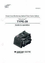
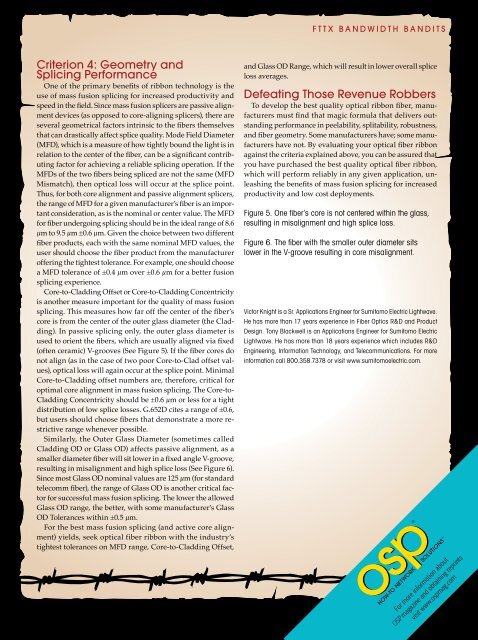
Core-to-Cladding Offset or Core-to-Cladding Concentricity<br />
is another measure important for the quality of mass fusion<br />
splicing. This measures how far off the center of the fiber’s<br />
core is from the center of the outer glass diameter (the Cladding).<br />
In passive splicing only, the outer glass diameter is<br />
used to orient the fibers, which are usually aligned via fixed<br />
(often ceramic) V-grooves (See Figure 5). If the fiber cores do<br />
not align (as in the case of two poor Core-to-Clad offset values),<br />
optical loss will again occur at the splice point. Minimal<br />
Core-to-Cladding offset numbers are, therefore, critical for<br />
optimal core alignment in mass fusion splicing. The Core-to-<br />
Cladding Concentricity should be ±0.6 µm or less for a tight<br />
distribution of low splice losses. G.652D cites a range of ±0.6,<br />
but users should choose fibers that demonstrate a more restrictive<br />
range whenever possible.<br />
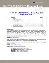
Similarly, the Outer Glass Diameter (sometimes called<br />
Cladding OD or Glass OD) affects passive alignment, as a<br />
smaller diameter fiber will sit lower in a fixed angle V-groove,<br />
resulting in misalignment and high splice loss (See Figure 6).<br />
Since most Glass OD nominal values are 125 µm (for standard<br />
telecomm fiber), the range of Glass OD is another critical factor<br />
for successful mass fusion splicing. The lower the allowed<br />
Glass OD range, the better, with some manufacturer’s Glass<br />
OD Tolerances within ±0.5 µm.<br />
For the best mass fusion splicing (and active core alignment)<br />
yields, seek optical fiber ribbon with the industry’s<br />
tightest tolerances on MFD range, Core-to-Cladding Offset,<br />
and Glass OD Range, which will result in lower overall splice<br />
loss averages.<br />
Defeating Those <strong>Revenue</strong> <strong>Robbers</strong><br />
To develop the best quality optical ribbon fiber, manufacturers<br />
must find that magic formula that delivers outstanding<br />
performance in peelability, splitability, robustness,<br />
and fiber geometry. Some manufacturers have; some manufacturers<br />
have not. By evaluating your optical fiber ribbon<br />
against the criteria explained above, you can be assured that<br />
you have purchased the best quality optical fiber ribbon,<br />
which will perform reliably in any given application, unleashing<br />
the benefits of mass fusion splicing for increased<br />
productivity and low cost deployments.<br />
Figure 5. One fiber’s core is not centered within the glass,<br />
resulting in misalignment and high splice loss.<br />
Figure 6. The fiber with the smaller outer diameter sits<br />
lower in the V-groove resulting in core misalignment.<br />
Victor Knight is a Sr. Applications Engineer for Sumitomo Electric Lightwave.<br />
He has more than 17 years experience in Fiber Optics R&D and Product<br />
Design. Tony Blackwell is an Applications Engineer for Sumitomo Electric<br />
Lightwave. He has more than 18 years experience which includes R&D<br />
Engineering, Information Technology, and Telecommunications. For more<br />
information call 800.358.7378 or visit www.sumitomoelectric.com.<br />
®<br />
For more information about<br />
OSP magazine and obtaining reprints<br />
visit www.ospmag.com<br />
<br />
®