How to install a concrete thrust block (SABI Vol 6)
- No tags were found...

You also want an ePaper? Increase the reach of your titles
YUMPU automatically turns print PDFs into web optimized ePapers that Google loves.
• •<br />
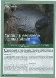
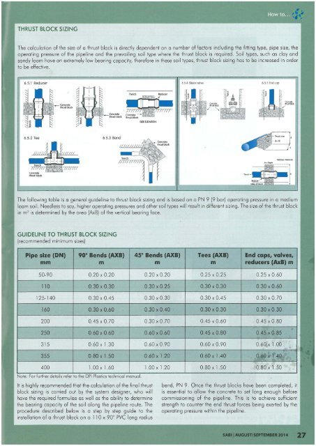
THRUST BLOCK SIZING<br />
The calculation of the size of a <strong>thrust</strong> <strong>block</strong> is directly dependent on a number of fac<strong>to</strong>rs including the fitting type, pipe size, the<br />
operating pressure of the pipeline and the prevailing soil type where the <strong>thrust</strong> <strong>block</strong> is required . Soil types, such as clay and<br />
sandy loam have an extremely low bearing capac ity, therefore in these soil types, <strong>thrust</strong> <strong>block</strong> sizing has <strong>to</strong> be increased in order<br />
<strong>to</strong> be effective.<br />
6.5.1 Reducer<br />
6.5.4 Sluicevalve 6.5.5 End ca p<br />
_<br />
<strong>concrete</strong><br />
<strong>thrust</strong> <strong>block</strong><br />
6.5.2 Tee<br />
Trench<br />
m 7T!77T71<br />
Redu(er, VoMlselc<br />
The following table is a general guideline <strong>to</strong> <strong>thrust</strong> <strong>block</strong> sizing and is based on a PN 9 (9 bar) operating pressure in a medium<br />
loam soil. Needless <strong>to</strong> say, higher operat ing pressures and other soil types will result in different sizing. The sizeof the <strong>thrust</strong> <strong>block</strong><br />
in m 2 is determined by the area (AxB) of the vertical bearing face.<br />
GUIDELINE TO THRUST BLOCK SIZING<br />
(recommended minimum sizes)<br />
Pipe size (DN ) 90° Bends (AXB) 45 ° Bends (AXB) Tees (AXB) End caps, valves,<br />
mm m m m reducers (AxB) m<br />
50-90 0.20 x 0.20 0.20 x 0.20 0.25 x 0.25 0.25 x 0.60<br />
110 0.30 x 0.30 0.30 x 0.25 0.30 x 0.30 0.30 x 0.60<br />
125-140 0.30 x 0.45 0.30 x 0.30 0.30 x 0.45 0.30 x 0.70<br />
160 0.30 x 0.60 0.30 x 0040 0.30 x 0.30 0.30 x 0.30<br />
200 0.45 x 0.70 0.30 x 0.70 0045 x 0.60 0.45 x 0 .80<br />
250 0.60 x 0.60 0.60 x 0.60 0.45 x 0.80 0.45 x 0.85<br />
315 0.60 x 1.30 0.60 x 0.90 0.60 x 0.90 0.60 x 1.00<br />
355 0.80 x 1.50 0.60 x 1.20 0.60 x lAO 0.60 x 1.40<br />
400 1.00 x 1.60 1.00 x 1.20 0.80 x 1.50 0.80 x 1.50<br />
Note : For further de<strong>to</strong>ils refer <strong>to</strong> the DPI Plcstics technical manual.<br />
It is highly recommended that the calculation of the final <strong>thrust</strong><br />
<strong>block</strong> sizing is carried out by the system designer, who will<br />
have the required formulae as well as the ability <strong>to</strong> determine<br />
the bearing capacity of the soil along the pipeline route. The<br />
procedure described below is a step by step guide <strong>to</strong> the<br />
<strong>install</strong>ation of a <strong>thrust</strong> <strong>block</strong> on a 110 x 90° PVC long radius<br />
bend, PN 9. Once the <strong>thrust</strong> <strong>block</strong>s have been completed, it<br />
is essential <strong>to</strong> allow the <strong>concrete</strong> <strong>to</strong> set long enough before<br />
commissioning of the pipeline . This is <strong>to</strong> achieve sufficient<br />
strength <strong>to</strong> counter the end <strong>thrust</strong> forces being exerted by the<br />
operating pressure within the pipel ine.<br />
<strong>SABI</strong>I AUGUST/SEPTEMBER 2014 27