CATALOGUE
sk - KIWA, spol. s ro, Nitra
sk - KIWA, spol. s ro, Nitra

Create successful ePaper yourself
Turn your PDF publications into a flip-book with our unique Google optimized e-Paper software.
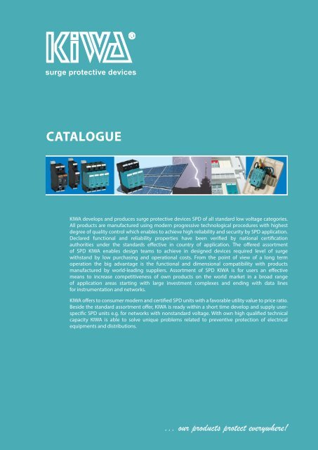
surge protective devices<br />
<strong>CATALOGUE</strong><br />
KIWA develops and produces surge protective devices SPD of all standard low voltage categories.<br />
All products are manufactured using modern progressive technological procedures with highest<br />
degree of quality control which enables to achieve high reliability and security by SPD application.<br />
Declared functional and reliability properties have been verified by national certification<br />
authorities under the standards effective in country of application. The offered assortment<br />
of SPD KIWA enables design teams to achieve in designed devices required level of surge<br />
withstand by low purchasing and operational costs. From the point of view of a long term<br />
operation the big advantage is the functional and dimensional compatibility with products<br />
manufactured by world-leading suppliers. Assortment of SPD KIWA is for users an effective<br />
means to increase competitiveness of own products on the world market in a broad range<br />
of application areas starting with large investment complexes and ending with data lines<br />
for instrumentation and networks.<br />
KIWA offers to consumer modern and certified SPD units with a favorable utility value to price ratio.<br />
Beside the standard assortment offer, KIWA is ready within a short time develop and supply userspecific<br />
SPD units e.g. for networks with nonstandard voltage. With own high qualified technical<br />
capacity KIWA is able to solve unique problems related to preventive protection of electrical<br />
equipments and distributions.<br />
... our products protect everywhere!
WHAT IS OVERVOLTAGE ?<br />
Impulse overvoltage<br />
Massive increase of electronics in all areas of human beings is connected with a necessity to protect electronic<br />
equipment from failure state occurance.<br />
In the past reasons of failures were searched for only in the individual equipment, nowadays this access is<br />
extended also to considering operating conditions of equipment from the view of overvoltage appearance in<br />
the given surroundings. Damages caused by impulse overvoltage are of higher order when comparing with<br />
the past, e.g. costs for insurance events caused by overvoltage in foreign insurance companies according to the<br />
statistics are ten of percents of the overall costs of insurance events remittance.<br />
Sources of overvoltage occurances are mainly atmospheric discharges, switch processes in distribution<br />
networks and switch processes of power components and equipment in technological processes. Atmospheric<br />
overvoltage is characteristic by high released energy which can threat directly (lightning current) or by<br />
overvoltage inducted at indirect lightning hits. Overvoltage frequency due to atmospheric discharges is given<br />
mainly by numbers of stormy days which achieves on average 25 a year in our country.<br />
Switch processes in distribution networks generate overvoltage impulses which are often transfered through<br />
capacitance of transformers from the high-voltage into the low-voltage networks. Frequency of their occurance<br />
is multiple times higher than in case of atmospheric discharge. Technological overvoltage origins in on/off<br />
switching mainly inductive and capacitive loads. The frequency of their occurance is multiple times higher in<br />
comparison with previous kinds of overvoltages.<br />
Overvoltage can be propagated out of its source in more ways. The lowest attenuation for its propagation<br />
represents the galvanic way created by power and telecomunication networks. Overvoltage propagation<br />
form the source to the place of interference can be reached also via capacity and inductive coupling or by<br />
electromagnetic induction. Overvoltage penetration into electric distributions can be also caused by high<br />
increase of basement earthing potential due to lightning hit into the object. Withstand of electric appliances<br />
to overvoltage comprises a part of its electromagnetic compatibility, it means an ability of electric appliance to<br />
work reliably in interfering electromagnetic surroundings. That is why the topic of overvoltage and overvoltage<br />
protection has been given more and more attention.<br />
www.kiwa.sk 27/2015<br />
The overvoltage protection principle<br />
Overvoltage protection consists of set of technical precautions which eliminate overvoltage to the value<br />
acceptable in the given point of electricity distribution. These precautions include mainly concept of<br />
interconnections of all non-live parts and interconnection of all live parts by overvoltage conductors to equal<br />
potential. SPDs have a very high resistance at nominal voltage thus they are an insulant. When increasing<br />
the voltage over their nominal voltage the resistance of SPDs starts to decrease very quickly and so they<br />
galvanicaly connect live parts with zero equipotential ground bus bar. Increased current flowing through SPD<br />
cause limitation of voltage increase on protected circuit. Thus the voltage on protected line does not exceed<br />
the level defined by standard and this way any damage on appliance or distribution system is prevented.<br />
Basic protection conditions against the impulse overvoltage caused by direct or indirect lightning hit are<br />
presented in the standard IEC 61024-1 which defines rules for outdoor and indoor protection against the<br />
lightning. EU standard EN 62305 about rules for building protection against the lightning sets only conditions<br />
for outdoor protection against lightning. Requirements for indoor protection with zone concepts of lightning<br />
protection are defined in IEC 1312-1.<br />
Minimum required withstand<br />
against the impulse overvoltage is<br />
defined by I STN EN 60664-1:2004-<br />
07, IEC 664, in terms of overvoltage<br />
category I to IV and it sets the<br />
possibility of transmission from one<br />
overvoltage category into a lower<br />
category by using the SPDs.<br />
Overvoltage category<br />
3
Standard IEC 61643-1 presents a distribution of SPD-s into classes of requirements I - B, II - C and III - D.<br />
All KIWA SPD-s comply the most recent requirements of standard EN 61643-11/A11.<br />
SPD Type 1 (class I, B) is intended for overvoltage category III according to the EN 33 0420, where the maximum<br />
overvoltage 4 kV is set by insulation coordination for the network 230/400V. This SPD serves for equalizing of<br />
potentials at lightning strike and it is connected to installation input in the main distributor.<br />
SPD Type 2 (class II, C) is intended for overvoltage category II where the maximum overvoltage 2,5 kV is set<br />
by insulation coordination for the network 230/400V. This SPD is intended to divert the energy of overvoltage<br />
impulses in electric distributions and it is installed mainly into sub distribution boards. It is also possible to<br />
install it into the main distributor together with SPD class I, but it is necessary insert between this stages an<br />
impact decoupling choke.<br />
SPD Type 3 (class III, D) is intended for overvoltage category I, where the maximum overvoltage 1,5 kV is set<br />
by insulation coordination for the network 230/400V. This SPD is intended to divert the energy of overvoltage<br />
impulse at the end of plug circuit or distributiors of electric machines equipment. In spite of the fact that<br />
presented standards require a complex installation of SPDs in step configuration of classes I (B), II (C), III (D),<br />
the individually installed SPD of class III is also able to divert a considerable part of overvoltage applied to the<br />
supply network.<br />
Operation security is also important at individual usage of SPD class III, which is given mainly by SPD design.<br />
SPD INSTALLATION<br />
Requirements for choice and way of SPD installation in electric appliaces of building is described in the<br />
regulation IEC 332000 Electric installations of buildings – protective devices against overvoltage<br />
and IEC 60364-53 Electric installation of buildings part 5-53 Choice and assembly of electric appliances, section<br />
534 Protection against overvoltage appliances. In this regulations is a description of layout and connection<br />
of SPDs for individual types of networks. The basic parameters of SPDs are there specified for individual<br />
areas of applications. These standards present also a need of energy coordination of individual levels in the<br />
overvoltage protection system ensuring that these levels are properly coordinated. The norm sets rules of<br />
insertion of impedance between individual levels of overvoltage protection which can be realized either by<br />
own impedance of sufficiently long line between individual levels or by insertion of decuppling chokes. Size<br />
of sufficient electric cable length is given by individual types of SPDs. In case of SPDs class I based on lightning<br />
arrester and SPD class II based on varistor is sufficient from the view of energy coordination security a line of<br />
the length approximately 15 m. In case of SPDs based on varistor e.g. PO I and PO II of KIWA assortment there<br />
was experimentaly found the same reaction period of both levels, thus the separation is sufficient at usage of<br />
cable approximately 1,5 m long. Impedance by integration of such a cable fully coordinates energy distribution<br />
between individual varistor levels even at most negative tolerance deviations of individual levels.<br />
For details see: „APPLICATION HANDBOOK“<br />
4
OVERVIEW OF SPD KIWA<br />
POm I LCF - SPD Type 1+2+3 (B+C+D)<br />
Page 7 - 12<br />
POm I LCF - are used for protection of mains and appliances against the effects of overvoltage<br />
wave caused by a close, direct or indirect lightning hit. Designed as one monoblock with<br />
varistor and gas filled spark gap connected in series which ensures a complete separation<br />
of L->N, N->PE, with zero residual currents. The units are manufactured in versions with or<br />
without remote signaling system. When installing, modules can be clipped to DIN rails 35<br />
mm.<br />
U n<br />
= 230 V AC<br />
I imp<br />
= 12,5 kA, 25 kA, 30 kA, 38 kA, 50 kA, 100 kA<br />
TN-C, TN-S, IT, TT<br />
POm I - SPD Type 1+ Type 2+ Type 3 (B+C+D)<br />
Page 13 - 14<br />
Used for protection of mains and appliances against the effects of overvoltage wave<br />
caused by a close, direct or indirect lightning hit. Designed as one monoblock. The units<br />
are manufactured in versions with or without remote signaling system. When installing,<br />
modules can be clipped to DIN rails 35 mm.<br />
U n<br />
= 230 V AC<br />
I imp<br />
= 25 kA<br />
TN-C, TN-S, IT, TT<br />
PO I - SPD Type 1+2+3 (B+C+D)<br />
Page 15 - 20<br />
PO I - are used to equalize potentials at striking of lightning. They are installed at the input<br />
of outer conductors to the main switching cabinet. These modules incorporate replaceable<br />
plug-in varistors and are also manufactured in versions with or without remote signaling<br />
system. When installing, modules can be clipped to DIN rails 35 mm.<br />
www.kiwa.sk 27/2015<br />
U n<br />
= 230 V AC<br />
I imp<br />
= 7 kA; 12,5 kA<br />
PO II - SPD Type 2+3 (C+D)<br />
PO II - are used to divert energy of overvoltage impulses in power distribution systems of<br />
objects. These modules are usually installed in subdistribution boards. The incorporated<br />
plug-in varistor is coded according to voltage. The units are manufactured in versions with<br />
or without remote signaling system. When installing, modules can be clipped to DIN rails<br />
35 mm.<br />
U<br />
n<br />
= 60, 120, 230, 385, 470,750 V AC<br />
I max<br />
= 40 kA<br />
TN-C, TN-S, IT, TT<br />
Page 21 - 26<br />
TN-C, TN-S, IT, TT<br />
SPD Type 3 (D) Page 27 - 35<br />
They are used as protection of end devices against surge impulses in electrical<br />
distributions. A common feature of SPDs type 3 is an original design with thermal<br />
disconnecting device, which is at once also a fire safety element. It is recommended<br />
to install it as close as possible to the protected device.<br />
1. POD-275 and POD S - are used as a supplementary protection of already installed power<br />
sockets, installing housings, canals or directly into end devices and instruments.<br />
2. RPO D - all versions are designed for installation on DIN rail inside the distributor of the<br />
end device<br />
- models (R) are fitted with remote signaling<br />
- models (F) are fitted with HF filter to eliminate interference coming from distribution<br />
network<br />
3. PO LED - Usage for LED lights as 2nd and 3rd level ( T2 medium and T3 fine protection) in<br />
3-level overvoltage protection concept. Protection against the transverse and longitudinal<br />
overvoltage (L/N, L/PE, N/PE). Optical or acoustical signalization of operational state.<br />
5
4. ZPO D - socket overvoltage protection devices are installed directly in standard<br />
sockets as its integral part:<br />
- manufactured in variant with optical indication of correct function (ZPO D) of<br />
overvoltage protection or with indication of defect (ZPOI D)<br />
- in case of varistor overloading the protective unit is disconnected while socket remains<br />
functional but without protection<br />
- simple installation<br />
5. ZPA D - are characterized by simple installation i.e. plugging into the standard mains<br />
socket. Manufactured in variants ZPA D, ZPA DFAX, ZPA DTV, ZPA DEth.<br />
TN-C, TN-S<br />
Overvoltage protection of communication lines for instrumentation<br />
and control<br />
Page 36 - 41<br />
These modules are used for protection of data entry in equipments of instrumentation<br />
and control systems. Individual types of overvoltage protections are designed for<br />
various application areas. Surge protective devices type DM are used for protection<br />
of measuring and control part of equipment entry, while those of type DN are used for<br />
protection of supply part of equipment output. These modules are manufactured in<br />
variants R (for distribution boards), M (modular) and P (integrated).<br />
Application area:<br />
BS, BST, BA, BAT – protection of instrumentation and control equipment with analog<br />
signal transfer (sensors 0/4 – 20 mA, binary signals). Protection of supply lines AC, DC.<br />
Frequency limit 100 kHz.<br />
CS, CC - protection of lines with analog or digital signal transfer. Cutoff frequency 3MHz.<br />
Transfer data rate up to 1.5 Mbit/s.<br />
U n<br />
= 8, 12, 16, 24, 48 V DC<br />
Overvoltage protection for Ethernet data networks<br />
Page 42<br />
The data network overvoltage protection DME is designed to protect LAN 100BaseT<br />
(CAT5). These units are manufactured in modular variant with protection of 2 pairs of<br />
wires.<br />
U n<br />
= 5 V DC<br />
transfer data rate = 100 Mbit/s<br />
Overvoltage protection for DC circuits of photovoltaic<br />
systems<br />
Page 43 - 56<br />
For protection of DC circuits of photovoltaic systems. These modules incorporate<br />
replaceable plug-in varistor and are also manufactured in versions with<br />
or without remote signaling system. When installing, modules can be clipped<br />
to DIN rails 35 mm.<br />
U CPV<br />
= up to 1000 V DC<br />
Fault signalization module Page 57<br />
Fault signalization modules MSP-24 and MSP-230 are designed for sound and light<br />
signalling of fault condition of surge protectors.<br />
6
POm I LCF<br />
For protection of mains and appliances in industrial buildings,<br />
administration buildings, buildings of civil amenities and detached<br />
houses against the effects of overvoltage wave caused by a close, direct<br />
or indirect lightning hit<br />
It decreases overvoltage and restricts overvoltage wave energy<br />
Installation: into the main distributor<br />
Usage as the 1st level T1 of overvoltage protection<br />
It provides overvoltage protection for appliances installed in the<br />
main distributor in the range of T1, T2 , T3 (coarse, medium and fine<br />
protection)<br />
High diverting capability provided by power varistors MOV<br />
and lightning arrester<br />
Zero leaking current (LCF version)<br />
Zero follow current<br />
Optical and remote signalization of operation state<br />
Multifunctional terminals for conductors<br />
Possibility of monoblock connection by bus bars<br />
SPD Type 1<br />
DIMENSIONS<br />
www.kiwa.sk 27/2015<br />
CONNECTION DIAGRAM<br />
POm I 3 LCF 35,3<br />
POm I 3 LCF 75<br />
POm I 3 LCF 90<br />
N-PE VERSION<br />
POm I N-PE 50<br />
I total = 50 kA<br />
POm I 4 LCF 50<br />
POm I 4 LCF 100<br />
POm I 4 LCF 120<br />
POm I N-PE 100<br />
I total = 100 kA<br />
LCF VERSION<br />
POm I 3+1 LCF 50<br />
POm I 3+1 LCF 100 POm I 1+1 LCF 50<br />
LCF version is version with zero leaking current<br />
and zero follow current<br />
Possibility of application in front of electricity meter**<br />
as well as after current breaker (**valid only with the<br />
agreement of appropriate electricity supplier)<br />
Varistor is connected in series with gas filled spark gap<br />
Signalling states<br />
green = OK<br />
red = out of operation,<br />
to be replaced immediately<br />
7
DELIVERY AND ASSEMBLY INSTRUCTION<br />
Completed from individual poles – using individual<br />
poles taken from store during the assembly process<br />
according to needs<br />
Delivered and assembled as one unit<br />
– simple installation<br />
POm I LCF 12,5<br />
I imp = 12,5 kA 3x POm I LCF 12,5<br />
I total = 37,5 kA 4x POm I LCF 12,5<br />
I total = 50 kA<br />
3x POm I LCF 12,5<br />
1x POm I N-PE 50<br />
I total = 50 kA<br />
POm I 3 LCF 37,5<br />
I total = 37,5 kA POm I 4 LCF 50<br />
I total = 50 kA<br />
POm I 3+1 LCF 50<br />
I total = 50 kA<br />
POm I LCF 25<br />
I imp = 25 kA<br />
3x POm I LCF 25<br />
I total = 75 kA<br />
4x POm I LCF 25<br />
I total = 100 kA<br />
POm I 3 LCF 75<br />
I total = 75 kA<br />
POm I 4 LCF 100<br />
I total = 100 kA<br />
3x POm I LCF 25<br />
1x POm I N-PE 100<br />
I total = 100 kA<br />
1x POm I LCF 25<br />
1x POm I N-PE 50<br />
I total = 50 kA<br />
POm I 3+1 LCF 100/25<br />
I total = 100 kA<br />
POm I 1+1 LCF 50/25<br />
I total = 50 kA<br />
POm I LCF 30<br />
I imp = 30 kA<br />
3x POm I LCF 30<br />
I total = 90 kA<br />
4x POm I LCF 30<br />
I total = 120 kA<br />
POm I 3 LCF 90<br />
I total = 90 kA<br />
POm I 4 LCF 120<br />
I total = 120 kA<br />
3x POm I LCF 30<br />
1x POm I N-PE 100<br />
I total = 100 kA<br />
1x POm I LCF 30<br />
1x POm I N-PE 50<br />
I total = 50 kA<br />
POm I 3+1 LCF 100/30<br />
I total = 100 kA<br />
POm I 1+1 LCF 50/30<br />
I total = 50 kA<br />
R VERSION<br />
Each product‘s modification<br />
containing varistor module,<br />
can be supplied with remote<br />
signalling system to identify<br />
the state of SPD.<br />
POm I R LCF 12,5 POm I R LCF 25 POm I R LCF 30<br />
POm I 4 R LCF 100<br />
8
TECHNICAL PARAMETERS<br />
ТYPE<br />
POm I<br />
KIWA<br />
N-PE<br />
L-N<br />
50 100 LCF 12,5 LCF 25 LCF 30<br />
Number of poles 1 1 1 1 1<br />
Nominal voltage U n 230 V~ 230 V~ 230 V~ 230 V~ 230 V~<br />
Max. operating voltage T1 T2 T3 U c 260 V~ 260 V~ 280 V~ 280 V~ 280 V~<br />
Voltage protection level T1 T2 T3 U p ≤1,5 kV ≤1,5 kV ≤1,5 kV ≤1,5 kV ≤1,5 kV<br />
Response time t A
POm I LCF BD<br />
For protection of mains and appliances in administration buildings, buildings<br />
of civil amenities and detached houses against effects of overvoltage wave<br />
caused by a close , direct or indirect lightning hit<br />
It decreases overvoltage and restricts overvoltage wave energy<br />
Installation: into the main distributor<br />
Usage as the 1st level T1 of overvoltage protection<br />
It provides overvoltage protection for appliances installed in the main<br />
distributor in the range of T1 , T2 , T3 (coarse, medium and fine protection)<br />
High diverting capability provided by power varistors MOV and lightning<br />
arrester<br />
Zero leaking current (LCF version)<br />
Zero follow current<br />
Optical and remote signalization of operation state<br />
Multifunctional terminals for conductors<br />
Possibility of monoblock connection by bus bars<br />
DIMENSION<br />
CONNECTION DIAGRAM<br />
POm I LCF BD 38 POm I 3 LCF BD 114<br />
LCF VERSION<br />
LCF version is version with zero leaking current and zero follow<br />
current<br />
Possibility of application in front of electricity meter**<br />
as well as after current breaker (**valid only with the agreement of<br />
appropriate electricity supplier)<br />
Varistor is connected in series with gas filled spark gap<br />
Signalling states<br />
green = OK<br />
red = out of operation,<br />
to be replaced immediately<br />
10
DELIVERY AND ASSEMBLY INSTRUCTION<br />
Completed from individual poles – using individual<br />
poles taken from store during the assembly<br />
process according to needs<br />
Delivered and assembled as one unit<br />
– simple installation<br />
SPD type 1<br />
POm I LCF BD 38<br />
I imp = 38 kA<br />
3x POm I LCF BD 38<br />
I total = 114 kA<br />
POm I 3 LCF BD 114<br />
I total = 114 kA<br />
R VERSION<br />
Each product‘s modification<br />
containing varistor module,<br />
can be supplied with remote<br />
signalling system to identify<br />
the state of SPD.<br />
POm I R LCF BD 38 POm I R LCF BD 114<br />
PRODUCT SPECIFICATION<br />
www.kiwa.sk 27/2015<br />
POm I 3 R LCF BD 114 280V/38 kA<br />
U c / I imp<br />
I total = common current I imp<br />
for apartments<br />
LCF, N-PE version<br />
R - remote signalling<br />
number of poles<br />
type SPD<br />
TYPE<br />
Order number<br />
POm I LCF BD 38 81.156<br />
POm I R LCF BD 38 81.157<br />
POm I 3 LCF BD 114 81.160<br />
POm I 3 R LCF BD 114 81.161<br />
Busbars<br />
Order number<br />
3 pol - QB 18 - 3 91.603<br />
11
TECHNICAL PARAMETERS<br />
TYPE<br />
POm I<br />
KIWA L-N<br />
LCF BD 38 LCF BD 114<br />
Number of poles 1 3<br />
Nominal voltage U n 230 V AC 230 V AC<br />
Max. operating voltage T1 T2 T3 U c<br />
280 V AC 280 V AC<br />
Voltage protection level T1 T2 T3 U p ≤1,5 kV ≤1,5 kV<br />
Response time t A
POm I 25<br />
For protection of mains and appliances in industrial buildings, administration<br />
buildings, buildings of civil amenities and detached houses against the<br />
effects of overvoltage wave caused by a close, direct or indirect lightning hit<br />
It decreases overvoltage and restricts overvoltage wave energy<br />
Installation: into the main distributor<br />
Usage as the 1st level T1 of overvoltage protection<br />
It provides overvoltage protection for appliances installed in the main<br />
distributor in the range of T1, T2 , T3 (coarse, medium and fine protection)<br />
High diverting capability provided by power varistors MOV<br />
and lightning arrester<br />
Optical and remote signalization of operation state<br />
Multifunctional terminals for conductors<br />
SPD Type 1<br />
DELIVERY AND ASSEMBLY INSTRUCTION<br />
POm I 25 POm I 1+1 50/25 POm I 3 75 POm I 4 100 POm I 3+1 100/25<br />
www.kiwa.sk 27/2015<br />
BASIC AND N-PE VERSION<br />
Basic version<br />
N-PE version<br />
PRODUCT SPECIFICATION<br />
SIGNALLING STATES<br />
Signalling states<br />
POm I 3 R 75 280 V/25 kA<br />
U c / I imp<br />
I total - common current I imp<br />
R - remote signalling<br />
number of poles<br />
type SPD<br />
Green = OK<br />
red = out of operation,<br />
to be replaced immediately<br />
Type<br />
Order No.<br />
POm I 25 81.250<br />
POm I R 25 81.255<br />
POm I 3 75 81.253<br />
POm I 3 R 75 81.257<br />
POm I 4 100 81.254<br />
POm I 4 R 100 81.258<br />
POm I 3+1 100/25 81.259<br />
POm I 3+1 R 100/25 81.260<br />
POm I 1+1 50/25 81.261<br />
POm I 1+1 R 50/25 81.262<br />
13
DIMENSIONS<br />
TECHNICAL PARAMETERS<br />
KIWA Type POm I<br />
L-N/PE<br />
Number of poles 1<br />
N-PE<br />
25 50 100<br />
Nominal voltage U n 230 V AC<br />
Max. operating voltage T1 T2 T3 U c 280 V AC 260 V AC<br />
Voltage protection level T1 T2 T3 U p ≤1,5 kV<br />
Response time t A
PO I<br />
For protection of mains and appliances in small industrial buildings,<br />
administration buildings, buildings of civic amenities, detached<br />
houses against the effects of overvoltage wave caused<br />
by a close, direct or indirect lightning hit<br />
Decreases overvoltage and restricts overvoltage wave energy<br />
Installation: into the main distributor<br />
Usage as the 1st level ( T1 , coarse protection) in a 3-level overvoltage<br />
protection concept<br />
Provides overvoltage protection for appliances placed in the main<br />
distributor in the range T1 , T2 , T3 (coarse, medium and fine<br />
protection)<br />
High diverting cable ability provided by power varistors MOV<br />
Version: basic part + plug-in protective modules<br />
Protective modules rotable with respect to the base through 180 o<br />
Optical and remote signalization of operation state<br />
Multifunctional terminals for conductors and bus bars<br />
SPD type 1<br />
DIMENSIONS<br />
www.kiwa.sk 27/2015<br />
BASIC VERSION<br />
Signalling states:<br />
green = OK<br />
red = out of operation,<br />
to be replaced immediately<br />
EWS VERSION<br />
Wear signalling states in EWS version:<br />
green = ОК<br />
yellow = replacement is recommended<br />
red = out of operation,<br />
to be replaced immediately<br />
PO I 0 PO I 1<br />
PO I 2<br />
PO I 3 PO I 4<br />
15
R and N-PE VERSION<br />
Optional version with remote signalling (R)<br />
Each product‘s modification containing<br />
varistor module, can be supplied with<br />
remote signalling system to identify<br />
a state of overvoltage protection device<br />
PO I 1+1 R<br />
PO I 1 R<br />
PO I 4 R<br />
PO I 2 R<br />
PO I 3 R<br />
N-PE monoblock version<br />
N-PE version<br />
PO I 0 N-PE<br />
PO I 3+1 m<br />
PO I 3+1m R<br />
PO I 1 +1<br />
PO I 1 N-PE<br />
INSTALLATION<br />
(R)<br />
Installation on DIN rail<br />
Cable labeling system using Dekafix replaceable strips<br />
Plug-in varistor can be turned through 180 o<br />
16<br />
11
www.kiwa.sk 27/2015<br />
KIWA<br />
TECHNICAL PARAMETERS<br />
TYPE<br />
PO I<br />
POm I<br />
L-N N-PE N-PE 50<br />
Number of poles 1 1 1<br />
Nominal voltage U n 230 V~ 230 V~ 230 V~<br />
Max. operating voltage T1 T2 T3 U c 280 V~ 260 V~ 260 V~<br />
Voltage protection level T1 T2 T3 U p ≤1,3 kV ≤1,5 kV ≤1,5 kV<br />
Response time t A
PO I e<br />
For protection of mains and appliances where no risk of a direct (lightning) hit to<br />
a building or supply network is present - LOW THREAT OF INSTALLATION. Used<br />
for objects with lightning protection level LPL IV - family houses without airtermination<br />
conductor, network supply by earth cable, situated inside dense<br />
build-up area objects and halls inside dense build up areas with high rise<br />
buildings.<br />
Decreases overvoltage and restricts overvoltage wave energy<br />
Installation: into the main distributor<br />
Usage as the 1st level ( T1 , coarse protection) in a 3-level overvoltage protection<br />
concept<br />
Provides overvoltage protection for appliances placed in the main distributor in<br />
the range T1 , T2 , T3 (coarse, medium and fine protection)<br />
High diverting cable ability provided by power varistors MOV<br />
Version: basic part + plug-in protective modules<br />
Protective modules rotable with respect to the base through 180°<br />
Optical and remote signalization of operation state<br />
Multifunctional terminals for conductors and bus bars<br />
DIMENSIONS<br />
PO I 4 e PO I 3 e PO I 1 e<br />
BASIC VERSION<br />
Signalling states:<br />
green = OK<br />
red = out of operation,<br />
to be replaced immediately<br />
PO I 0 e PO I 1 e<br />
PO I 3 e PO I 4 e<br />
18
R and N-PE VERSION<br />
Optional version with remote signalling (R)<br />
Each product‘s modification containing<br />
varistor module, can be supplied with<br />
remote signalling system to identify a state<br />
of overvoltage protection device.<br />
SPD type 1<br />
PO I 1+1 e R<br />
PO I 1 e R<br />
PO I 3 e R<br />
N-PE version<br />
PO I 0 e N-PE<br />
PO I 4 e R<br />
PO I 1 +1 e<br />
PO I 1 e N-PE<br />
INSTALLATION<br />
www.kiwa.sk 27/2015<br />
Installation on DIN rail<br />
Cable labeling system using Dekafix replaceable strips<br />
Plug-in varistor can be turned through 180°<br />
(R)<br />
19
TECHNICAL PARAMETERS<br />
KIWA TYPE PO I e<br />
Number of poles 1 1<br />
Nominal voltage U n 230 V AC 230 V AC<br />
Max. operating voltage T1 T2 T3 U c 280 V AC 260 V AC<br />
Voltage protection level T1 T2 T3 U p ≤1,3 kV ≤1,5 kV<br />
Response time t A
PO II<br />
For protection of mains and appliances in industrial buildings,<br />
administration buildings, buildings of civil amenities, detached<br />
houses and flats against the overvoltage<br />
Decreases overvoltage and restricts overvoltage energy wave<br />
caused by induction and switching activities in the low-voltage<br />
power supply<br />
Installation: into the sub-distribution board<br />
Usage as the 2nd level ( T2 , medium protection) in 3-level overvoltage<br />
protection concept<br />
Provides protection against the overvoltage for appliances placed in<br />
the sub-distribution board in the range of T2 , T3 (medium, fine<br />
protection)<br />
High diverting capability provided by power varistors MOV and by<br />
gas filled spark gaps<br />
Version: basic part + plug-in protective modules<br />
Protective modules rotable with respect the base through180 o<br />
Optical and remote signalization of operation state<br />
Optical signalization of wear state (EWS version)<br />
Zero leakage current (LCF version)<br />
Multifunctional terminals for conductors and bus bars<br />
SPD Type 2<br />
DIMENSIONS<br />
www.kiwa.sk 27/2015<br />
BASIC VERSION<br />
Signalling states:<br />
green = OK<br />
red = out of operation,<br />
to be replaced immediately<br />
EWS VERSION<br />
Wear signalling states in EWS version:<br />
green = ОК<br />
yellow = replacement is recommended<br />
red = out of operation,<br />
to be replaced immediately<br />
PO II 0 PO II 1<br />
PO II 2<br />
PO II 3 PO II 4<br />
21
LCF VERSION<br />
LCF version is overvoltage protection with suppressed residual current<br />
The device can be connected in front of electricity meter<br />
Varistor is connected in series with gas filled spark gap<br />
PO II 0 PO II 1<br />
PO II 2<br />
PO II 3 PO II 4<br />
R and N-PE VERSION<br />
Optional version with remote signalling (R)<br />
PO II 3 +1 R<br />
PO II 1 +1 R<br />
PO II 1 R<br />
PO II 4 R<br />
PO II 2 R<br />
PO II 3 R<br />
N-PE version<br />
Each product‘s modification containing varistor<br />
module, can be supplied with remote signalling<br />
system to identify a state of overvoltage<br />
protection device.<br />
PO II 0 N-PE<br />
PO II 3 +1 PO II 1 +1 PO II 1 N-PE<br />
22
INSTALLATION<br />
Installation on DIN rail<br />
Cable labeling system using Dekafix replaceable strips<br />
Plug-in varistor can be turned through 180 o<br />
(R)<br />
SPD Type 2<br />
TECHNICAL PARAMETERS<br />
www.kiwa.sk 27/2015<br />
TYPE<br />
PO II<br />
KIWA<br />
L-N<br />
280 V 75 V 130 V 385 V 550 V<br />
N-PE<br />
Number of poles 1 1 1 1 1 1<br />
Nominal voltage U n 230 V~ 60 V~ 120 V~ 385 V~ 470 V~ 230 V~<br />
Max. operating voltage T2 T3 U c 280 V~ 75 V~ 130 V~ 385 V~ 550 V~ 260 V~<br />
Voltage protection level T2 T3 U p ≤1,45 kV ≤0,7 kV ≤0,85 kV ≤1,8 kV ≤2,65 kV ≤1,45 kV<br />
Response time t A
PRODUCT SPECIFICATION<br />
PO II<br />
3+1 280 V/40 kA<br />
U c / I max<br />
EWS; LCF version<br />
R - remote signalling<br />
number of poles<br />
type SPD<br />
Order number<br />
TYPE<br />
U c 280V 75V 130V 385V 550V<br />
PO II 1 82.001 82.021 82.025 82.033 82.043<br />
PO II 1 R 82.005 82.023 82.029 82.037 82.047<br />
PO II 1 EWS 82.068<br />
PO II 1 R EWS 82.070<br />
PO II 1+1 82.017<br />
PO II 1+1 R 82.019<br />
PO II 1 LCF 82.064<br />
PO II 1 R LCF 82.066<br />
PO II 2 82.002 82.022 82.026 82.034 82.044<br />
PO II 2 R 82.006 82.024 82.030 82.038 82.048<br />
PO II 2 EWS 82.069<br />
PO II 2 R EWS 82.071<br />
PO II 2+1 82.062 82.051<br />
PO II 2+1 R 82.063 82.052<br />
PO II 2 LCF 82.065<br />
PO II 2 R LCF 82.067<br />
Order number<br />
TYPE<br />
U c 280V 75V 130V 385V 550V<br />
PO II 3 82.003 82.027 82.035 82.045<br />
PO II 3 R 82.007 82.031 82.039 82.049<br />
PO II 3 EWS 82.013<br />
PO II 3 R EWS 82.015<br />
PO II 3+1 82.018 82.041<br />
PO II 3+1 R 82.020 82.042<br />
PO II 3 LCF 82.009<br />
PO II 3 R LCF 82.011<br />
PO II 4 82.004 82.028 82.036 82.046<br />
PO II 4 R 82.008 82.032 82.040 82.050<br />
PO II 4 EWS 82.014<br />
PO II 4 R EWS 82.016<br />
PO II 4 LCF 82.010<br />
PO II 4 R LCF 82.012<br />
PO II 0 82.053 82.056 82.057 82.058 82.059<br />
PO II 0 LCF 82.054<br />
PO II 0 EWS 82.055<br />
TYPE<br />
U c<br />
Order number<br />
260V<br />
PO II 0 N-PE 82.060<br />
PO II 1 N-PE 82.061<br />
24
PO II G 280V/40kA<br />
COMPLIES WITH STANDARTS EN 61643-11:2012<br />
PO II G complies with new standarts: EN 61643-11: 2012, thereby is<br />
guaranteed higher reliability and safety<br />
It decreases overvoltage and restricts overvoltage energy wave caused<br />
by induction and switching activities in the low-voltage power supply<br />
For protection of mains and appliances in industrial buildings,<br />
administration buildings, buildings of civil amenities, detached<br />
houses and flats against the overvoltage<br />
Installation: into the sub-distribution board<br />
Usage as the 2nd level ( T2 , medium protection) in 3-level overvoltage<br />
protection concept<br />
Provides protection against the overvoltage for appliances placed in the<br />
sub-distribution board in the range of T2 , T3 (medium, fine protection<br />
High diverting capability provided by power varistors MOV and by gas<br />
filled spark gaps<br />
Version: basic part + plug-in protective modules<br />
Protective modules rotable with respect the base through180 o<br />
Optical and remote signalization of operation state<br />
Multifunctional terminals for conductors and bus bars<br />
New productions series G<br />
* illustration photo<br />
SPD Type 2<br />
CONNECTION DIAGRAM<br />
SIGNALLING STATES<br />
www.kiwa.sk 27/2015<br />
PO II G 1 280V/40kA<br />
INSTALLATION<br />
Installation on DIN rail<br />
Cable labeling system using Dekafix replaceable strips<br />
Plug-in varistor can be turned through 180 o<br />
green = OK<br />
red = out of operation,<br />
to be replaced immediately<br />
(R)<br />
25
TECHNICAL PARAMETERS<br />
KIWA Type PO II G 280V/40kA<br />
L-N<br />
280 V AC<br />
Number of poles 1 1<br />
N-PE<br />
Nominal voltage U n 230 V AC 230 V AC<br />
Max. operating voltage T2 T3 U c 280 V AC 260 V AC<br />
Voltage protection level T2 T3 U p ≤1,45 kV ≤1,45 kV<br />
Response time t A
OVERVOLTAGE PROTECTION MODULES<br />
PODA-275, PODA-275S, POD-275S and POD S<br />
Usage as 3rd level ( T3 , fine protection) in 3-level<br />
overvoltage protection concept<br />
It decreases overvoltage and reduces overvoltage<br />
wave energy caused by induction and switching<br />
processes in the connected low voltage network<br />
Installation into the cable channel and installation<br />
boxes or to terminalss of the protected appliance<br />
Protection against the transverse and longitudinal<br />
overvoltage (L/N, L/PE, N/PE)<br />
Protective effect provided by a varistor<br />
combined with spark gap<br />
Optical and/or acoustical signalization of<br />
operational state<br />
PODA-275<br />
PODA-275S<br />
SPD Type 3<br />
POD-275S<br />
POD S<br />
www.kiwa.sk 27/2015<br />
DIMENSIONS<br />
PODA-275<br />
with acoustic signalling<br />
PODA-275S<br />
with acoustic<br />
and optic signalling<br />
RED<br />
POD-275S<br />
with optic signalling<br />
GREEN<br />
POD S<br />
with optic signalling<br />
ENDINGS<br />
OF CONNECTING<br />
CONDUCTORS<br />
without wire end cable<br />
an ending ferrule lug<br />
27
TECHNICAL PARAMETERS<br />
KIWA TYPE PODA-275 PODA-275S POD-275S POD S<br />
Nominal voltage U n 230 V~ 230 V~<br />
Max. operating voltage U c (L-N) 275 V~ 275 V~<br />
Open curcuit voltage U oc 3 kV 4 kV<br />
Voltage protection level U p (L-N) ≤0,9 kV ≤1 ,2 kV<br />
U p (L-PE) ≤1,5 kV ≤1,5 kV<br />
U p (N-PE) ≤1,2 kV ≤1,5 kV<br />
Response time t A (L-N)
INSTALLATION<br />
CONNECTION DIAGRAM<br />
POD is connected to the electric installation by conductors with wire end<br />
ferrules, cable lugs or without any endings – according to the realization.<br />
POD is parallel-connected to distribution conductors of electric installation<br />
or directly to clamps of the protected appliance. It is necessary to respect<br />
the marking of conductors at the assembly (L, N, PE).<br />
SPD Type 3<br />
Optic indicators element of POD S, POD-275S<br />
and PODA-275S is either sticked or luted at assembly into<br />
the hole of 4 mm diameter in the cover of socked.<br />
Although the surge protective unit POD itself provides protection against overvoltage, it is recommended that its installation is<br />
performed with a front-end SPD of the Type 2 in accordance with the concept of overvoltage protection coordination.<br />
www.kiwa.sk 27/2015<br />
APPLICATIONS<br />
Module of surge protective device POD is designed for<br />
assembly into installation channels or floor systems;<br />
additional assembly into installation boxes under the sockets<br />
– for all common types of sockets, it is imbedded into electro-installation boxes<br />
with minimum depth of 40 mm;<br />
assembly into installation boxes;<br />
directly into electric machines, appliances and equipment.<br />
29
PO LED<br />
Usage for LED lihts as 2nd and 3rd level ( T2 medium<br />
and T3 , fine protection) in 3-level overvoltage protection<br />
concept<br />
It decreases overvoltage and reduces overvoltage wave<br />
energy caused by induction and switching processes in<br />
the connected low voltage network<br />
Installation into the cable channel and installation boxes<br />
or to terminalss of the protected appliance<br />
Protection against the transverse and longitudinal<br />
overvoltage (L/N, L/PE, N/PE)<br />
Protective effect provided by a varistor combined with<br />
spark gap<br />
Optical and/or acoustical signalization of operational<br />
state<br />
DELIVERY AND ASSEMBLY INSTRUCTION<br />
PO II LED 230V/30kA<br />
PO LED-Wzk/zS PO LED-W/zS PO LED-K/zS<br />
DIMENSIONS<br />
CONNECTION DIAGRAM<br />
PO II LED 230V/30kA<br />
PO LED-Wzk/zS<br />
PO LED-W/zS<br />
PO LED-K/zS<br />
30
www.kiwa.sk 27/2015<br />
TECHNICAL PARAMETERS<br />
TYP PO II LED 230V/30kA PO LED-Wzk/zS PO LED-W/zS PO LED-K/zS<br />
Connection wire 2,5mm 2 terminal block, max. 1,5mm 2 wire 1,5mm 2<br />
L (mm) 160 - 160<br />
Nominal voltage U n 230 V AC 230 V AC<br />
Max. operation voltage U c 275 V AC 350 V AC<br />
Nominal discharge current (8/20) T2 I n 20 kA 5 kA<br />
Max. discharge current (8/20) I max 30 kA 10 kA<br />
Open curcuit voltage U oc 20 kV 10 kV<br />
Voltage protection level U p (L-N) ≤1,4 kV ≤1,5 kV<br />
PRODUCT SPECIFICATION<br />
PO/PO II LED - /<br />
Type<br />
Order No.<br />
PO LED-Wzk/zS 92.200<br />
PO LED-W/zS 92.202<br />
PO LED-K/zS 92.201<br />
PO II LED 230V/30kA 92.203<br />
U p (L-PE) ≤1,4 kV ≤1 kV<br />
U p (N-PE) ≤1,4 kV ≤1 kV<br />
Response time t A (L-N)
OVERVOLTAGE PROTECTION SOCKETS<br />
ZPO D, ZPOI D<br />
Usage as 3rd level ( T3 , fine protection) in 3-level protection concept against<br />
overvoltage<br />
It decreases overvoltage and reduces overvoltage wave energy caused by<br />
induction and switching processes in the connected low voltage network<br />
Installation into the installation boxes<br />
Protection against the transverse and longitudinal overvoltage (L/N, L/PE, N/PE)<br />
Protective effect provided by a varistor combined with spark gap<br />
Optical signalization state of overvoltage protection:<br />
- basic version – a green indicator signals OK function<br />
- inverse version (I) – a red indicator signals OUT / faulty<br />
Type<br />
TECHNICAL PARAMETERS<br />
new series<br />
Max. operation voltage U c 280 V AC 280 V AC<br />
Nominal voltage U n 230 V AC 230 V AC<br />
Nominal discharge current (8/20) I n 2,5 kA -<br />
Max. discharge current (8/20) I max 5 kA -<br />
Open circuit voltage U oc 4 kV 3 kV<br />
Voltage protection level at 5 kA (8/20)<br />
L-N U P ≤1,5 kV ≤0,9 kV<br />
L-PE<br />
U P ≤1,5 kV<br />
≤1,5 kV<br />
L/N<br />
U P ≤1,2 kV<br />
≤1,2 kV<br />
Response time<br />
L/N<br />
t A<br />
< 25 ns<br />
< 100 ns<br />
L(N)/PE<br />
t A<br />
Prospective short-circuit<br />
current of a power supply<br />
I p<br />
6 kA ef<br />
Overcurrent protection<br />
≤16 A with disconnection chars. B, C, D<br />
Status indication of TDD<br />
(Thermic Disconnecting Device)<br />
green (OK) or red (OUT)<br />
Products comply with norms<br />
STN EN 61643-11/A11<br />
IEC 61643-1<br />
VDE 0675-06<br />
typ 3 T3<br />
class III<br />
Klasse D<br />
Tango sockets<br />
ZPO D1B-TA ZPO D2B-TA ZPO D ATA1 iS-3kV ZPO D ATA2 iS-3kV<br />
Classic sockets<br />
ZPO D11-CL ZPO D21-CL ZPOI D11-CL ZPOI D21-CL<br />
Mosaic sockets<br />
ZPO D LMO1 iS-3kV<br />
ZPO D LMO1 iS-3kV<br />
*Tango® is ABB, Ltd. companies registered trademark<br />
PRODUCT SPECIFICATION<br />
ZPO D - - UOC open circuit voltage<br />
iS - status indication - red (OUT)<br />
zS - status indication - green (OK)<br />
number of socket<br />
socket type<br />
Type<br />
Order No.<br />
producer<br />
type of SPD<br />
ZPO D1B - TA, without box 92.005<br />
ZPO D2B - TA 92.008<br />
Type<br />
Order No.<br />
ZPO D11 - CL 92.035<br />
ZPO D1M/74111-MOSAIC 92.011<br />
ZPOI D1B - TA 92.069<br />
ZPO D1M/74114-MOSAIC 92.012<br />
ZPOI D2B - TA 92.070<br />
Type - new series<br />
Order No.<br />
ZPO D LMO1 iS-3kV white 92.162/20<br />
ZPO D LMO1 iS-3kV red 92.162/10<br />
ZPO D ATA1 iS-3kV white 92.166/10<br />
ZPO D ATA2 iS-3kV white 92.164/10<br />
ZPO D LMI1 zS-4kV white 92.165/10<br />
ZPOI D11 - CL 92.071<br />
ZPOI D21 - CL 92.072<br />
ZPO D2R - TA 92.094<br />
ZPOI D1R - TA 92.098<br />
ZPOI D1 - TA 92.110<br />
ZPOI D2R - TA 92.116<br />
Other overvoltage protection sockets on demand.<br />
32
DISTRIBUTION BOX OVERVOLTAGE PROTECTION<br />
RPO D, RPO DS<br />
Usage as 3rd level ( T3 , fine protection) in 3-level overvoltage protection concept<br />
It decreases overvoltage and reduces overvoltage wave energy caused by<br />
induction and switching processes in the connected low voltage network<br />
Installation on 35 mm DIN rail<br />
Protection against the transverse and longitudinal overvoltage (L/N, L/PE, N/PE)<br />
Protective effect provided by a varistor combined with spark gap<br />
Optical and remote signalling of operation state<br />
SPD Type 3<br />
DIMENSIONS<br />
CONNECTION DIAGRAM<br />
only RPO DS<br />
www.kiwa.sk 27/2015<br />
KIWA TYPE 230 V 115 V 48 V 24 V 12V<br />
Nominal voltage U n 230 V~ 115 V/50 Hz 48 V ~/= 24 V ~/= 12 V ~/=<br />
Rated load current I L 16 A 16 A 16 A 16 A 16 A<br />
Nominal discharge current (8/20) I n 2,5 kA 2,5 kA 2,5 kA 1 kA 1 kA<br />
Maximum discharge current (8/20) I max 5 kA 5 kA 5 kA 2 kA 2 kA<br />
Open circuit voltage U oc 4 kV 4 kV 4 kV 4 kV 4 kV<br />
Voltage protection level at I max<br />
L(N)/PE U P < 1,5 kV < 0,8 kV < 1,1 kV < 0,8 kV ≤0,8 kV<br />
L/N U P < 1,2 kV < 0,7 kV < 0,4 kV < 0,2 kV ≤0,12 kV<br />
Response time<br />
TECHNICAL PARAMETERS<br />
L/N t A < 25 ns<br />
L(N)/PE t A < 100 ns<br />
Prospective short-circuit<br />
current of a power supply<br />
Overcurrent protection gL/gG<br />
Status indication of TDD<br />
(Thermic Disconnecting Device)<br />
Mounting on profiled DIN rail<br />
PRODUCT SPECIFICATION<br />
Order number<br />
TYPE<br />
230 V 115 V 48 V 24 V 12V<br />
RPO D 92.024 92.081 92.083 92.082 92.160<br />
RPO DS 92.025 92.084 92.086 92.085 92.161<br />
I p<br />
6 kA ef / 50 Hz<br />
≤16 A with disconnection characteristic B, C, D<br />
green (OK)<br />
35 x 7,5 mm<br />
33
DISTRIBUTION BOX OVERVOLTAGE PROTECTION<br />
with HF filter<br />
RPOD F 6, RPOD F 16, RPOD F 6-L, RPOD F 16-L and RPOD F 16-LI<br />
Usage as 3rd level ( T3 , fine protection) in 3-level<br />
overvoltage protection concept<br />
It decreases overvoltage and reduces overvoltage<br />
wave energy caused by induction and switching<br />
processes in the connected low voltage network<br />
Prevents propagation of HF disturbances<br />
Installation on 35 mm DIN rail<br />
Protection against the transverse and longitudinal<br />
overvoltage (L/N, L/PE, N/PE)<br />
Protective effect provided by a varistor in combined with<br />
spark gap<br />
Integrated HF filter<br />
Optical and remote signalling of operation state<br />
DIMENSIONS<br />
CONNECTION DIAGRAM<br />
IN<br />
OUT<br />
RPOD F 6<br />
RPOD F 16<br />
RPOD R F 6<br />
RPOD R F 16<br />
RPOD F 6-L<br />
RPOD F 16-L<br />
RPOD R F 6-L<br />
RPOD R F 16-L<br />
RPOD F 16-LI<br />
34
TYPE<br />
TECHNICAL PARAMETERS<br />
RPOD F 6<br />
RPOD R F 6<br />
RPOD F 16<br />
RPOD R F 16<br />
RPOD F 6-L<br />
RPOD R F 6-L<br />
RPOD F 16-L<br />
RPOD R F 16-L<br />
RPOD F 16-LI<br />
SPD Type 3<br />
www.kiwa.sk 27/2015<br />
Nominal voltage U n 230 V AC 230 V AC 230 V AC 230 V AC 230 V AC<br />
Rated load current I L 6 A 16 A 6 A 16 A 16 A<br />
Max. operating voltage U c 255 V AC 255 V AC 255 V AC 255 V AC 255 V AC<br />
Open circuit voltage U oc 4 kV 4 kV 4 kV 4 kV 4 kV<br />
Voltage protection level<br />
U P<br />
L/N 0,9 kV 0,9 kV 1,2 kV 1,2 kV 1,2 kV<br />
N/PE 1,2 kV 1,2 kV 1,2 kV 1,2 kV 1,2 kV<br />
L/PE 1,5 kV 1,5 kV 1,5 kV 1,5 kV 1,5 kV<br />
Response time<br />
t A<br />
L/N
OVERVOLTAGE PROTECTION<br />
FOR INSTRUMENTATION AND CONTROL<br />
Overvoltage protectors class DM (for instrumentation and control) and DN<br />
(for power supply) are intended for protection of data input of devices in<br />
measuring and regulating systems, which in general are extremly sensitive to<br />
overvoltage damage.<br />
KIWA SPDs for instrumentation and control are characterized by<br />
- a high diverting capacity up to 20 kA (8/20) according to the type,<br />
- a high suppression efficiency of overvoltage events,<br />
- simple installation,<br />
- long operational life.<br />
Two basic versions available:<br />
R - distributor panel<br />
M - modular<br />
DIMENSIONS<br />
DM-xx-M<br />
DM-xxx-R<br />
DN-xxx-R<br />
CONNECTION DIAGRAM<br />
The 2-level<br />
CS, CC protectors. The separation<br />
between levels is realized<br />
by inductance-free resistors.<br />
The application area is protection<br />
of analogue circuits operating at<br />
a frequency of up to 3 MHz and digital<br />
circuits with transfer rate up to 1.5<br />
MBit/s. Diverting ability reaches a value<br />
of 10 kA (8/20).<br />
CS<br />
The 3-level<br />
BS, BA.. protectors. The separation<br />
between levels is realized by chokes. The<br />
application area is protection of analogue<br />
signals with low frequency, circuits with<br />
current loops (0/4 - 20 mA) and two-state<br />
(ON/OFF) signals. With respect tot he low<br />
transfer resistance, they are also suitable<br />
to protect AC, DC supply distributions.<br />
BS<br />
BA<br />
BA1<br />
CC<br />
BST<br />
BAT<br />
36
TECHNICAL PARAMETERS<br />
Connection diagram: BS, BST<br />
Nominal voltage U n 8 V 12 V 16 V 24 V 48 V<br />
Max. operating voltage U c 1,15. U n<br />
Rated loated current<br />
I L<br />
DN class<br />
1 A<br />
DM class<br />
100 mA<br />
Nominal discharge current (8/20) I n 10 kA<br />
Max. discharge current (8/20) I max 20 kA<br />
Voltage protection level for I max<br />
U p<br />
line / line ≤ 15 V ≤ 30 V ≤ 40 V ≤ 50 V ≤ 92 V<br />
line / signal earth ≤ 80 V ≤ 110 V ≤ 120 V ≤ 260 V ≤ 480 V<br />
Response time<br />
t A<br />
line / line ≤ 1 ns ≤ 1 ns ≤ 1 ns ≤ 1 ns ≤ 1 ns<br />
line / signal earth ≤ 25 ns ≤ 25 ns ≤ 25 ns ≤ 25 ns ≤ 25 ns<br />
Cut-off frequency<br />
f o<br />
DN class<br />
70 kHz<br />
DM class<br />
100 kHz<br />
Serial impedance / line<br />
L, R<br />
DN class<br />
max. 250 µH / max. 2 Ω<br />
DM class<br />
max. 150 µH / max. 1 Ω<br />
Operating temperature range<br />
-25 o C ... +80 o C<br />
Connection<br />
input/output: terminal for 0,5 - 2,5 mm 2 wire<br />
Instrumentation and Control<br />
Connection diagram: CS, CC<br />
www.kiwa.sk 27/2015<br />
Nominal voltage U n 8 V=/ 5 V~ 12 V=/ 8 V~ 16 V= / 11 V~ 24 V= / 17 V~ 48 V=/ 34 V~<br />
Max. operating voltage U c 1,15. U n<br />
Rated loated current I L 100 mA<br />
Nominal discharge current (8/20) I n 5 kA<br />
Max. discharge current (8/20) I max 10 kA<br />
Voltage protection level for I max<br />
U p<br />
line / line 15 V ≤ 23 V ≤ 45 V ≤ 36 V ≤ 72 V<br />
line / signal earth 15 V ≤ 23 V ≤ 25 V ≤ 36 V ≤ 72 V<br />
Voltage protection level for 1 kV/µs<br />
U sp<br />
line / protected earth<br />
≤ 450 V<br />
Response time<br />
t A<br />
line / line<br />
≤ 1 ns<br />
line / signal earth<br />
≤ 1 ns<br />
line (sign.earth) /protected earth<br />
≤ 100 ns<br />
Cut-off frequency/ baud rate f o 3 MHz / 1,5 MBit/s<br />
Longitudinal impedance / line R L max. 10 Ω<br />
Operating temperature range<br />
-25 o C ... +80 o C<br />
Connection<br />
R version<br />
input/output: terminal for 0,5 - 2,5 mm 2 wire<br />
M version<br />
input: 0,5 mm 2 cable, 100 mm long<br />
output: 0,2 mm 2 wire, 100 mm long<br />
37
Connection diagram: BA, BA1, BAT<br />
Nominal voltage U n 8 V 12 V 16 V 24 V 48 V<br />
Max. operating voltage U c 1,15. U n<br />
Rated load current<br />
I L<br />
DN class<br />
1 A<br />
DM class<br />
100 mA<br />
Nominal discharge current (8/20) I n 10 kA<br />
Max. discharge current (8/20) I max 20 kA<br />
Voltage protection level for I max<br />
U p<br />
line / sign. earth ≤ 13 V ≤ 19 V ≤ 21 V ≤ 33 V ≤ 72 V<br />
line / line ≤ 26 V ≤ 38 V ≤ 42 V ≤ 66 V ≤ 144 V<br />
Response time<br />
t A<br />
line / sign. earth<br />
≤ 1 ns<br />
Cut-off frequency<br />
f o<br />
DN class<br />
70 kHz<br />
DM class<br />
100 kHz<br />
Serial impedance / line<br />
L, R<br />
DN class<br />
max. 250 µH / max. 2 Ω<br />
DM class<br />
max. 150 µH / max. 1 Ω<br />
Operating temperature range<br />
-25 o C ... +80 o C<br />
Connection<br />
input/output: terminal for 0,5 - 2,5 mm 2 wire<br />
PRODUCT SPECIFICATION<br />
D - - /<br />
Nominal voltage (V)<br />
version: R - on a DIN35 (distributor) rail or M - modular<br />
type of product - (BS, BST, CS, CC, BA, BA1, BAT ) corresponding to connection diagram<br />
class of overvoltage protection (M - instrumentation and control 0,1A, or N - supply 1A)<br />
Order number<br />
TYPE<br />
8 V 12 V 16 V 24 V 48 V<br />
DM-BS-R 94.038<br />
DN-BS-R 94.013 94.023<br />
DM-BST-R 94.031<br />
DN-BST-R 94.050<br />
DM-CS-M 94.001 94.016 94.018 94.040<br />
DM-CS-R 94.002 94.017 94.019 94.034<br />
DM-CC-R 94.022 94.035 94.057<br />
DM-BA-R 94.043 94.045 94.033 94.032<br />
DN-BA-R 94.044 94.039 94.066<br />
DM-BA1- R 94.063 94.065 94.046<br />
DN-BA1-R 94.064 94.010 94.048<br />
DM-BAT-R 94.047<br />
DN-BAT-R 94.036<br />
38
OVERVOLTAGE PROTECTION<br />
FOR INSTRUMENTATION AND CONTROL<br />
DM-CCT-R<br />
It is used as a protection of appliances against the overvoltage, which is propagating through<br />
data and communication lines. It enables the protection of two wires lines or of two one wire<br />
lines (symmetrical or asymmetrical systems). It is commonly used in the area of measuring,<br />
controlling, and the area of digital and analogue information transmission equipment.<br />
The SPD has been created as the two-stage system with the stepwise overvoltage<br />
reduction down to allowable values. In the first stage are used the efficient<br />
spark plugs while fast suppressing diodes are used in the second stage. The correct operation<br />
requests the proper connection according to this recomandation, respecting connecting diagram<br />
as it is printed on the housing.<br />
The SPD is encased in the plastic housing designed for mounting on DIN 35 rail.<br />
DIMENSIONS<br />
Instrumentation and Control<br />
www.kiwa.sk 27/2015<br />
CONNECTION DIAGRAM<br />
line<br />
signal earth<br />
line<br />
protected earth<br />
shielding<br />
protected<br />
device<br />
39
TECHNICAL PARAMETERS<br />
Nominal voltage U n 8 V= 12 V= 16 V= 24 V= 48 V=<br />
Max. operating voltage U c 1,15. U n<br />
Rated load current I L 100 mA<br />
Nominal discharge current (8/20) I n 5 kA<br />
Max. discharge current (8/20) I max 10 kA<br />
Max. discharge current (10/350) I max 2,5 kA<br />
Voltage protection level for I max<br />
U p<br />
line / line 25 V ≤ 23 V ≤ 29 V ≤ 36 V ≤ 72 V<br />
line / sign. earth 15 V ≤ 23 V ≤ 29 V ≤ 36 V ≤ 72 V<br />
Voltage protection level for 1 kV/µs<br />
line / protection earth<br />
≤ 450 V<br />
sign. earth /protection earth<br />
Response time<br />
t A<br />
line / line<br />
≤ 1 ns<br />
line / sign. earth<br />
≤ 1 ns<br />
line / protection earth<br />
≤ 100 ns<br />
sign. earth / protection earth<br />
≤ 100 ns<br />
shielding / protection earth<br />
≤ 100 ns<br />
Limit frequency / baud rate f o 3 MHz / 1,5 MBit/s<br />
Imput resistance (line / sig. earth) R V ≤ 1 MΩ<br />
Longitudinal impedance / line R L max. 10 Ω<br />
Operating temperature range<br />
-25 o C ... +80 o C<br />
Connection input/output: terminal for cable 0,5 - 2,5 mm 2 ; wire 0,2 - 4 mm 2<br />
Products comply with norms IEC 61643-21<br />
C2; D1<br />
PRODUCT SPECIFICATION<br />
D - - /<br />
nominal voltage (V)<br />
version: R - on a DIN35 (distributor) rail<br />
type of product - (CCT) corresponding to connection diagram<br />
class of overvoltage protection (M - instrumentation and control 0,1A)<br />
Order number<br />
TYPE<br />
8 V 12 V 16 V 24 V 48 V<br />
DM-CCT-R 94.058 94.059 94.060 94.061 94.062<br />
40
DM485-4DB25<br />
The DM485-4DB25 overvoltage protection module is designed to protect the of<br />
electronical equipment using the RS-485 and RS-422 data interface. The module is<br />
suitable for use in lightning protection zone LPZ 1 (within buildings)<br />
The protective effect of overvoltage module is achieved by the combination of<br />
coarse and fine overvoltage protection. The coarse protection is provided by spark<br />
gaps, fine protection by a circuit with fast suppression diodes. It protects against<br />
symmetrical and asymmetrical overvoltage surges (between wires / wires and the<br />
earth).<br />
The module is equipped with a D-SUB25 junction connectors. The connection<br />
of the module is realised straight to the input connector of protected interface, or<br />
is connected to it with short connecting cable.<br />
The condition for achievement of the full protective effect is to connect the<br />
green-yellow conductor of the module to the source of earth potential. In case<br />
that the protected equipment is a device of class I, then the fully complying<br />
source of the earth potential is the frame of equipment. In case that the<br />
protected equipment is a device class II or class III, then the green-yellow<br />
conductor shall be connected to the earth rail of the equipotential distribution<br />
of the building or to the PE (PEN) rail of the main distribution.<br />
DIMENSIONS<br />
Instrumentation and Control<br />
TECHNICAL PARAMETERS<br />
www.kiwa.sk 27/2015<br />
Nominal discharge current (8/20)<br />
line - line, line - GND I n 2,5 kA<br />
PE - GND I n 2,5 kA<br />
Max. discharge current (8/20)<br />
line - line, line - GDN I max 5 kA<br />
PE - GDN I max 5 kA<br />
lines together - GDN I max 10 kA<br />
Nominal voltage U n 12 V=<br />
Max. operating voltage U c 15 V=<br />
Voltage protection level (at I max )<br />
line - line, line - GND U p ≤ 35 V<br />
PE - GDN U p ≤ 650 V<br />
Inserted impedance<br />
10 Ω<br />
Baud rate<br />
10 Mbit/s<br />
Response time t A ≤ 1 ns<br />
PRODUCT SPECIFICATION<br />
TYPE<br />
Order number<br />
DM485-4DB25.A 94.020<br />
DM485-4DB25.B 94.021<br />
CONNECTION<br />
DM485-4DB25.A<br />
DM485-4DB25.B<br />
input output input output<br />
D-Sub25F D-Sub25M D-Sub25M D-Sub25F<br />
Protection<br />
earth<br />
protected<br />
lines<br />
30 cm yellow-green wire with M4 forked<br />
terminal*<br />
1, 2, 3, 4<br />
* alternative lenghts of wire, or alternative terminals on<br />
demand<br />
41
Ethernet<br />
OVERVOLTAGE PROTECTION for Ethernet 100BaseT network<br />
DME100TX-4RJ, DME100TX-4RJ-R<br />
Protection of data inputs for LAN Ethernet 100BaseT site devices in lightning protection<br />
zone LPZ 1 (inside buildings). The full protective effects are only achieved with correct<br />
earthing of the overvoltage protection.<br />
The DME100T protection modules are connected between the equipment to be protected<br />
(workstation, server, HUB,...)and the unprotected network. Due to their small size, they<br />
can be fitted directly onto the protected equipment. The advantage of such installation is<br />
that there is no need to install a connection of earthing wire as this function is provided<br />
by the frame of the protected equipment.<br />
DME100TX-4RJ<br />
is SPD module for protection of the computer network 100BaseT. It protects 2 pairs of wires.<br />
It is equipped with two RJ45 connectors, which are interchangeable - each connector can<br />
act as input or output. The unprotected output of LAN shall be connected with a patch<br />
cable to one connector of the module, and the second connector is connected with cable<br />
to the input of the protected device.<br />
DME100TX-4RJ-R is a surge protector designed for DIN rail mounting. The potential PE is<br />
connected via the DIN rail holder which is connected to the PE.<br />
Fine one-stage protection. The protection effect provides the circuit combining<br />
suppressor diodes and avalanche diodes. It also provides protection against symmetrical<br />
and asymmetrical overvoltage surges (between individual wires / wires and the earth).<br />
DIMENSIONS<br />
TECHNICAL PARAMETERS<br />
Nominal discharge current (8/20)<br />
line - line I n 300 A<br />
line - earth I n 300 A<br />
tienenie - earth I n 1 kA<br />
Max. discharge current (8/20)<br />
line - line I max 350 A<br />
line - earth I max 350 A<br />
shielding - earth I max 2 kA<br />
Nominal voltage U n 5 V DC<br />
Max. operating voltage U c 7 V DC<br />
Voltage protection level (at I max )<br />
line - line, line - earth U p ≤ 45 V<br />
shielding - earth U p ≤ 600 V<br />
Insered impedance -<br />
Baud rate<br />
100 Mbit/s<br />
Response time t A ≤ 1 ns<br />
CONNECTION<br />
input<br />
RJ45 connector<br />
output<br />
RJ45 connector<br />
protection earth<br />
M4 screw<br />
protected wires 2 pairs of wires, line 1, 2, 3, 6 *<br />
* other lines are not connected<br />
PRODUCT SPECIFICATION<br />
TYPE<br />
Order number<br />
DME100TX-4RJ 94.007<br />
DME100TX-4RJ-R 94.042<br />
www.kiwa.sk 27/2015<br />
42
EXAMPLES OF INSTALLATION:<br />
43
SPD Type 2<br />
PO II 3 PH<br />
For protection of DC circuit photovoltaic systems with operating voltage up to 1000 V DC<br />
3-pole protection with enhanced withstand against failure of insulation against the earth<br />
Plug-in protectives modules<br />
Varistor modules for protection against overvoltage<br />
Optical signalization of operation state<br />
Remote signalization of operation state (R version)<br />
Protective modules rotable with respect to the base through 180 o<br />
Multifunctional terminals for conductors and bus bars<br />
DIMENSIONS<br />
CONNECTION DIAGRAM<br />
+ PE<br />
-<br />
R VERSION<br />
PO II 3 R PH<br />
Optional version with remote signalling (R)<br />
PO II 3 PH<br />
PO II 3 PH<br />
Each product‘s modification containing varistor module, can be supplied with remote signalling system to identify a state of overvoltage<br />
protection device.<br />
www.kiwa.sk 27/2015<br />
44
INSTALLATION<br />
(R)<br />
Instalation on DIN rail<br />
Cable labeling system using Dekafix replaceable strips<br />
Plug-in varistor can be turned through 180°<br />
TECHNICAL PARAMETERS<br />
KIWA TYPE PO II 3 PH PO II 3 PH<br />
Number of poles 3 3<br />
Max. operating voltage T2 U cPV<br />
600 V= 1000 V=<br />
Nominal discharge current (8/20) T2 I n 20 kA 20 kA<br />
Max. discharge current (8/20) T2 I max 40 kA 40 kA<br />
Voltage protection level at 5 kA (8/20)<br />
U p<br />
L+/L- 2,6 kV 4 kV<br />
L+-/PE 2,6 kV 4 kV<br />
Response time t A
SPD Type 2<br />
POPV II 3 F 1000 V DC<br />
POPV II 2 F 600 V DC<br />
POPV are surge protective devices designed for application in area of photovoltaic systems with DC circuits.<br />
For protection of DC circuits of photovoltaic systems with operating<br />
voltage up to 1000 V DC<br />
Plug-in protectives modules<br />
Varistor modules for protection against overvoltage<br />
Optical signalization of operation state<br />
Remote signalization of operation state (R version)<br />
Protective modules rotable with respect to the base through 180 o<br />
DIMENSIONS<br />
POPV II 3 F R 1000 V DC<br />
POPV II 2 F R 600 V DC<br />
CONNECTION DIAGRAM<br />
POPV II 3 F 1000 V DC<br />
POPV II 2 F 600 V DC<br />
Signalling states:<br />
BASIC VERSION<br />
green = OK<br />
red = out of operation,<br />
to be replaced immediately<br />
R VERSION<br />
POPV II 2 F 600 V DC<br />
POPV II 3 F 1000 V DC<br />
Optional version with remote signalling (R)<br />
for the identification of the overvoltage protection state<br />
POPV II 3 F R 1000 V DC POPV II 2 F R 600 V DC<br />
www.kiwa.sk 27/2015<br />
46
INSTALLATION<br />
(R)<br />
Installation on DIN rail<br />
Cable labeling system using Dekafix replaceable strips<br />
Plug-in varistor can be turned through 180 o<br />
TECHNICAL PARAMETERS<br />
ТYPE POPV II 3 F 1000 V DC POPV II 2 F 600 V DC<br />
Number of poles 3 2<br />
Max. operating voltage U CPV 1000 V= 600 V=<br />
Voltage protection level at<br />
U p<br />
L+/L- ≤ 4,2 kV ≤ 4,2 kV<br />
L+L-/PE ≤ 4,2 kV ≤ 2,65 kV<br />
Response time t A<br />
L+/L- < 25 ns < 25 ns<br />
L+L-/PE < 25 ns < 25 ns<br />
Nominal discharge current (8/20) I n 15 kA 15 kA<br />
Max. discharge current (8/20) I max 40 kA 40 kA<br />
Short-circuit withstand I SCWPV 200 A 200 A<br />
Signalling changeover contact M3/0.25 Nm, 0,2 ... 1,5 mm 2 , max. 250 V~/1A<br />
Status indication of TDD<br />
(Thermic Disconnecting Device)<br />
Min. ... max. tightening torque<br />
Connecting conductor cross section<br />
green (OK) / red(OUT)<br />
2 ... 3 Nm<br />
- wire 4 ... 35 mm 2<br />
- cord 4 ... 25 mm 2<br />
Operating temperature range<br />
- 40 ... +70 o C<br />
Degree of protection IP 20<br />
Dimensions 97 x 64 x 52,5 mm 97 x 64 x 35 mm<br />
Mounting on profiled DIN rail<br />
35 x 7,5 mm<br />
Products comply with norms<br />
UTE C 61-740-51<br />
Class II<br />
PRODUCT SPECIFICATION<br />
POPV II<br />
3 F R<br />
1000 V DC<br />
TYPE<br />
Order number<br />
U CPV<br />
R - remote signalling<br />
UTE C 61-740-51<br />
number of poles<br />
POPV II 3 F 1000 V DC 82.107<br />
POPV II 3 F R 1000 V DC 82.108<br />
POPV II 0 F 1000 V DC 82.109<br />
type SPD<br />
POPV II 2 F 600 V DC 82.125<br />
POPV II 2 F R 600 V DC 82.126<br />
POPV II 0 F 600 V DC 82.127<br />
47
SPD Type 2<br />
PO II 1 PV 100VDC<br />
For protection of DC circuit with operating voltage up to 100 V<br />
For protection of AC circuit with operating voltage up to 75 V<br />
Plug-in protectives modules<br />
Varistor modules for protection against overvoltage<br />
Optical signalization of operation state<br />
Remote signalization of operation state (R version)<br />
Protective modules rotable with respect to the base through 180 o<br />
DIMENSIONS<br />
CONNECTION DIAGRAM<br />
R VERSION<br />
PO II 1 R PV 100VDC<br />
Optional version with remote signalling (R)<br />
INSTALLATION<br />
Instalation on DIN rail<br />
Cable labeling system<br />
using Dekafix replaceable strips<br />
Plug-in varistor can be turned through 180°<br />
(R)<br />
www.kiwa.sk 27/2015<br />
48
TECHNICAL PARAMETERS<br />
KIWA TYPE PO II 1 PV 100VDC<br />
Number of poles 1<br />
Max. operating voltage U c 75 V AC<br />
Max. operating voltage U c 100 V DC<br />
Max. discharge current (8/20) I max 40 kA<br />
Nominal discharge current (8/20) I n 10 kA<br />
Voltage protection level U p ≤ 0,4 kV<br />
Voltage protection level at I n = 20 kA U p ≤ 0,5 kV<br />
Response time t A < 25 ns<br />
Open circuit voltage U oc 6 kV<br />
Prospective short-circuit<br />
current of a power supply<br />
I p<br />
25 kA ef<br />
Overcurrent protection gL/gG<br />
≤ 125 A<br />
Signalling changeover contact M3/0.25 Nm, max. 1,5 mm 2 , max. 250 V AC/1 A<br />
Status indication of TDD (Thermic Disconnecting Device)<br />
green (OK)/red (OUT)<br />
Min. ... max. tightening torque<br />
2 .. 3 Nm<br />
Connecting conductor cross section: - wire 4 ... 35 mm 2<br />
Operating temperature range<br />
- cord 4 ... 25 mm2<br />
- 40 ... +70 o C<br />
Degree of protection IP 20<br />
Colour - plug-in varistor turquoise blue, RAL 5018<br />
- holder black; RAL 9011<br />
Dimensions<br />
Mounting on profiled DIN rail<br />
Products comply with norms<br />
STN EN 61643-11/A11<br />
IEC 61643-1<br />
VDE 0675-06<br />
97 x 64 x 17,5 mm<br />
35 x 7,5 mm<br />
typ 2 T2 + typ 3 T3<br />
Class II + Class III<br />
Klasse C + Klasse D<br />
PRODUCT SPECIFICATION<br />
PO II<br />
1 PV 100V DC<br />
Max. operating voltage U c<br />
PV - possibility to use for photovoltaic systems<br />
R - remote signalling<br />
number of poles<br />
type SPD<br />
TYPE<br />
Order number<br />
PO II 1 PV 100VDC 82.143<br />
PO II 1 R PV 100VDC 82.144<br />
PO II 0 PV 100VDC 82.145<br />
49
SPD Type 2<br />
PO II 2 PV 100V DC<br />
PO II 3 PV 200V DC<br />
PO II PV are surge protective devices designed for application in area of photovoltaics systems.<br />
For protection of DC circuits of photovoltaic systems with operating<br />
voltage up to 200 V DC<br />
Plug-in protectives modules<br />
Varistor modules for protection against overvoltage<br />
Optical signalization of operation state<br />
Remote signalization of operation state (R version)<br />
Protective modules rotable with respect to the base through 180 o<br />
*<br />
*<br />
DIMENSIONS<br />
50<br />
PO II 2 R PV 100V DC PO II 3 R PV 200V DC<br />
CONNECTION DIAGRAM<br />
PO II 3 PV 200V DC<br />
PO II 2 PV 100V DC<br />
BASIC VERSION<br />
Signalling states:<br />
green = OK<br />
red = out of operation,<br />
to be replaced immediately<br />
R VERSION<br />
PO II 2 PV 100V DC *<br />
PO II 3 PV 200V DC *<br />
Optional version with remote signalling (R)<br />
for the identification of the overvoltage protection state<br />
PO II 3 R PV 200V DC * PO II 2 R PV 100V DC *<br />
*Illustration photo<br />
www.kiwa.sk 27/2015
INSTALlATION<br />
Installation on DIN rail<br />
Cable labeling system using Dekafix replaceable strips<br />
Plug-in varistor can be turned through 180 o<br />
(R)<br />
TECHNICAL PARAMETERS<br />
ТYPE PO II 2 PV 100V DC PO II 3 PV 200V DC<br />
Number of poles 2 3<br />
Max. operating voltage U CPV 100 V DC 200 V DC<br />
Voltage protection level at U p<br />
L+/L- ≤ 0,9 kV ≤ 0,9 kV<br />
L+L-/PE ≤ 0,45 kV ≤ 0,9 kV<br />
Response time<br />
t A<br />
L+/L- < 25 ns < 25 ns<br />
L+L-/PE < 25 ns < 25 ns<br />
Nominal discharge current (8/20) I n 15 kA 15 kA<br />
Max. discharge current (8/20) I max 40 kA 40 kA<br />
Short-circuit withstand I SCWPV 200 A 200 A<br />
Signalling changeover contact M3/0.25 Nm, 0,2 ... 1,5 mm 2 , max. 250 V~/1A<br />
Status indication of TDD<br />
(Thermic Disconnecting Device)<br />
green (OK) / red (OUT)<br />
Min. ... max. tightening torque<br />
2 ... 3 Nm<br />
Connecting conductor cross section<br />
- wire 4 ... 35 mm 2<br />
- cord 4 ... 25 mm 2<br />
Operating temperature range<br />
- 40 ... +70 o C<br />
Degree of protection IP 20<br />
Dimensions 97 x 64 x 52,5 mm 97 x 64 x 35 mm<br />
Mounting on profiled DIN rail<br />
35 x 7,5 mm<br />
Products comply with norms<br />
UTE C 61-740-51<br />
Class II<br />
PRODUCT SPECIFICATION<br />
PO II<br />
3 R PV 200V DC<br />
Max. operating voltage U CPV<br />
PV - possibility to use for photovoltaic systems<br />
R - remote signalling<br />
number of poles<br />
type SPD<br />
TYPE<br />
Order number<br />
PO II 2 PV 100V DC 82.150<br />
PO II 2 R PV 100V DC 82.151<br />
PO II 3 PV 200V DC 82.152<br />
PO II 3 R PV 200V DC 82.153<br />
51
SPD Type 1<br />
PO I 3 PV<br />
PO I 5 PV<br />
For protection of DC photovoltaic systems with operating voltage<br />
up to 1000 V DC<br />
3-pole protection with enhanced withstand<br />
against failures of insulation against the earth<br />
Plug-in protectives modules<br />
Varistor modules for protection against overvoltage<br />
Optical signalization of operation state<br />
Remote signalization of operation state (R version)<br />
Protective modules rotable with respect to the base through 180 O<br />
DIMENSIONS<br />
PO I 3 PV<br />
PO I 5 PV<br />
CONNECTION DIAGRAM<br />
PO I 3 PV<br />
PO I 5 PV<br />
www.kiwa.sk 27/2015<br />
52
BASIC VERSION<br />
Signalling states:<br />
green = OK<br />
red = out of operation,<br />
to be replaced immediately<br />
PO I 3 PV<br />
PO I 5 PV<br />
R and PE VERSION<br />
Optional version with remote signalling (R)<br />
PO I 5 R PV PO I 3 R PV<br />
INSTALLATION<br />
Installation on DIN rail<br />
Cable labeling system using Dekafix replaceable strips<br />
Plug-in varistor can be turned through 180 o<br />
(R)<br />
53
SPD Type 1<br />
TECHNICAL PARAMETERS<br />
KIWA ТYPE PO I 3 PV PO I 5 PV<br />
Number of poles 3 5<br />
Max. operating voltage T1, T2 U CPV 600 V= 1000 V=<br />
Voltage protection level at I n T1, T2<br />
U p<br />
L+/L- ≤ 2,8 kV ≤ 5,6 kV<br />
L+L-/PE ≤ 2,8 kV ≤ 4,2 kV<br />
Response time<br />
t A<br />
L+/L- < 25 ns < 25 ns<br />
L+L-/PE < 25 ns < 25 ns<br />
Impulse current (10/350)<br />
I imp<br />
L+/L-<br />
12,5 kA<br />
L+L-/PE 12,5 kA 12,5 kA<br />
Nominal discharge current (8/20) I n 30 kA<br />
Max. discharge current (8/20) I max 50 kA<br />
Prospective short-circuit<br />
current of a power supply<br />
I p<br />
25 kA ef<br />
Overcurrent protection gL/gG<br />
≤160 A<br />
Residual current I PE
EXAMPLES OF INSTALLATION FOR PHOTOVOLTAIC - DC SIDE<br />
EXAMPLES OF INSTALLATION FOR PHOTOVOLTAIC - AC SIDE<br />
55
56<br />
www.kiwa.sk 27/2015
MSP-24<br />
MSP-230<br />
MSP<br />
Fault signalization module MSP-24 and MSP 230<br />
It is designed for sound and light signalling of fault condition of surge<br />
protectors<br />
It is supplied in two versions:<br />
MSP-24 for 24 V AC/DC<br />
MSP-230 for 48 ÷ 230 V AC<br />
Modules can be used as a signalling unit, also in other applications, such<br />
as machinery equipment etc.<br />
DIMENSIONS<br />
MSP-24<br />
MSP-230<br />
www.kiwa.sk 27/2015<br />
WIRING DIAGRAM<br />
MSP-24<br />
MSP-230<br />
TECHNICAL PARAMETERS AND PRODUCT SPECIFICATION<br />
TYPE MSP-24 MSP-230<br />
Power supply Voltage U N<br />
24 V AC/DC 48 ÷ 230 V AC<br />
Power supply current I N<br />
20 mA 20 mA<br />
Frequency f 4,1 kHz /65 dB 4,1 kHz /65 dB<br />
Order number 94.121 94.122<br />
Remote<br />
signalling<br />
contact<br />
Remote<br />
signalling<br />
contact<br />
57
58<br />
EXAMPLES OF „PO KIWA“ APPLICATIONS
Quality of KIWA products is demonstrated by certificates from authorized EU testing laboratories<br />
59
Order No. Index<br />
60<br />
SPD - Type 1<br />
Order No. Page 7-14<br />
81.101 POm I N-PE 50 260V/50kA<br />
81.104 POm I LCF 12,5 280V/12,5kA<br />
81.107 POm I R LCF 12,5 280V/12,5kA<br />
81.121 POm I N-PE 100 260V/100kA<br />
81.124 POm I LCF 25 280V/25kA<br />
81.125 POm I R LCF 25 280V/25kA<br />
81.126 POm I LCF 30 280V/30kA<br />
81.127 POm I R LCF 30 280V/30kA<br />
81.128 POm I 4 LCF 100 280V/25kA<br />
81.129 POm I 4 R LCF 100 280V/25kA<br />
81.130 POm I 3 LCF 75 280V/25kA<br />
81.131 POm I 3 R LCF 75 280V/25kA<br />
81.132 POm I 3 LCF 90 280V/30kA<br />
81.133 POm I 3 R LCF 90 280V/30kA<br />
81.134 POm I 4 LCF 120 280V/30kA<br />
81.135 POm I 4 R LCF 120 280V/30kA<br />
81.136 POm I 3 LCF 37,5 280V/12,5kA<br />
81.137 POm I 3 R LCF 37,5 280V/12,5kA<br />
81.138 POm I 4 LCF 50 280V/12,5kA<br />
81.139 POm I 4 R LCF 50 280V/12,5kA<br />
81.140 POm I 3+1 LCF 50 280V/12,5kA<br />
81.141 POm I 3+1 R LCF 50 280V/12,5kA<br />
81.142 POm I 3+1 LCF 100/25 280V/25kA<br />
81.143 POm I 3+1 R LCF 100/25 280V/25kA<br />
81.144 POm I 1+1 LCF 50/30 280V/30kA<br />
81.145 POm I 1+1 R LCF 50/30 280V/30kA<br />
81.150 POm I 1+1 LCF 50/25 280V/25kA<br />
81.151 POm I 1+1 R LCF 50/25 280V/25kA<br />
81.152 POm I 3+1 LCF 100/30 280V/30kA<br />
81.153 POm I 3+1 R LCF 100/30 280V/30kA<br />
81.156 POmI LCF BD 38 280/38kA<br />
81.157 POmI R LCF BD 38 280/38kA<br />
81.160 POmI LCF BD 114 280/38kA<br />
81.161 POmI R LCF BD 114 280/38kA<br />
81.250 POm I 25 280V/25kA<br />
81.255 POm I R 25 280V/25kA<br />
81.253 POm I 3 75 280V/25kA<br />
81.257 POm I 3 R 75 280V/25kA<br />
81.254 POm I 4 100 280V/25kA<br />
81.258 POm I 4 R 100 280V/25kA<br />
81.259 POm I 3+1 100/25 280V/25kA<br />
81.260 POm I 3+1 R 100/25 280V/25kA<br />
81.261 POm I 1+1 50/25 280V/25kA<br />
81.262 POm I 1+1 R 50/25 280V/25kA<br />
Order No. Page 15-20<br />
81.001 PO I 1 280V/12,5kA<br />
81.002 PO I 2 280V/12,5kA<br />
81.003 PO I 3 280V/12,5kA<br />
81.004 PO I 4 280V/12,5kA<br />
81.005 PO I 1 R 280V/12,5kA<br />
81.006 PO I 2 R 280V/12,5kA<br />
81.007 PO I 3 R 280V/12,5kA<br />
81.008 PO I 4 R 280V/12,5kA<br />
81.009 PO I 1+1 280V/12,5kA<br />
81.011 PO I 1+1 R 280V/12,5kA<br />
81.013 PO I 3 EWS 280V/12,5kA<br />
81.014 PO I 4 EWS 280V/12,5kA<br />
81.015 PO I 3 R EWS 280V/12,5kA<br />
81.016 PO I 4 R EWS 280V/12,5kA<br />
81.017 PO I 0 280V/12,5kA<br />
81.018 PO I 0 N-PE 260V/12,5kA<br />
81.019 PO I 1 N-PE 260V/12,5kA<br />
81.020 PO I 0 EWS 280V/12,5kA<br />
81.023 PO I 1 EWS 280V/12,5kA<br />
81.024 PO I 2 EWS 280V/12,5kA<br />
81.025 PO I 1 R EWS 280V/12,5kA<br />
81.026 PO I 2 R EWS 280V/12,5kA<br />
81.027 PO I 3+1m 280V/12,5kA<br />
81.028 PO I 3+1m R 280V/12,5kA<br />
81.029 PO I 3+1m EWS 280V/12,5kA<br />
81.030 PO I 3+1m R EWS 280V/12,5kA<br />
81.031 PO I 1+1m 280V/12,5kA<br />
81.032 PO I 1+1m R 280V/12,5kA<br />
81.200 PO I 1 e 280V/7kA<br />
81.201 PO I 3 e 280V/7kA<br />
81.202 PO I 1 e R 280V/7kA<br />
81.203 PO I 3 e R 280V/7kA<br />
81.204 PO I 1+1 e 280V/7kA<br />
81.205 PO I 1+1 e R 280V/7kA<br />
81.206 PO I 3+1 e 280V/7kA<br />
81.207 PO I 3+1 e R 280V/7kA<br />
81.208 PO I 0 e 280V/7kA<br />
81.209 PO I 0 e N-PE 260V/25kA<br />
81.210 PO I 4 e 280V/7kA<br />
81.211 PO I 4 e R 280V/7kA<br />
SPD - Type 2<br />
Order No. Page 21-26<br />
82.001 PO II 1 280V/40kA<br />
82.002 PO II 2 280V/40kA<br />
82.003 PO II 3 280V/40kA<br />
82.004 PO II 4 280V/40kA<br />
82.005 PO II 1 R 280V/40kA<br />
82.006 PO II 2 R 280V/40kA<br />
82.007 PO II 3 R 280V/40kA<br />
82.008 PO II 4 R 280V/40kA<br />
82.009 PO II 3 LCF 280V/40kA<br />
82.010 PO II 4 LCF 280V/40kA<br />
82.011 PO II 3 R LCF 280V/40kA<br />
82.012 PO II 4 R LCF 280V/40kA<br />
82.013 PO II 3 EWS 280V/40kA<br />
82.014 PO II 4 EWS 280V/40kA<br />
82.015 PO II 3 R EWS 280V/40kA<br />
82.016 PO II 4 R EWS 280V/40kA<br />
82.017 PO II 1+1 280V/40kA<br />
82.018 PO II 3+1 280V/40kA<br />
82.019 PO II 1+1 R 280V/40kA<br />
82.020 PO II 3+1 R 280V/40kA<br />
82.021 PO II 1 75V/40kA<br />
82.022 PO II 2 75V/40kA<br />
82.023 PO II 1 R 75V/40kA<br />
82.024 PO II 2 R 75V/40kA<br />
82.025 PO II 1 130V/40kA<br />
82.026 PO II 2 130V/40kA<br />
82.027 PO II 3 130V/40kA<br />
82.028 PO II 4 130V/40kA<br />
82.029 PO II 1 R 130V/40kA<br />
82.030 PO II 2 R 130V/40kA<br />
82.031 PO II 3 R 130V/40kA<br />
82.032 PO II 4 R 130V/40kA<br />
82.033 PO II 1 385V/40kA<br />
82.034 PO II 2 385V/40kA<br />
82.035 PO II 3 385V/40kA<br />
82.036 PO II 4 385V/40kA<br />
82.037 PO II 1 R 385V/40kA<br />
82.038 PO II 2 R 385V/40kA<br />
82.039 PO II 3 R 385V/40kA<br />
82.040 PO II 4 R 385V/40kA<br />
82.041 PO II 3+1 385V/40kA<br />
82.042 PO II 3+1 R 385V/40kA<br />
82.043 PO II 1 550V/40kA<br />
82.044 PO II 2 550V/40kA<br />
82.045 PO II 3 550V/40kA<br />
82.046 PO II 4 550V/40kA<br />
82.047 PO II 1 R 550V/40kA<br />
82.048 PO II 2 R 550V/40kA<br />
82.049 PO II 3 R 550V/40kA<br />
82.050 PO II 4 R 550V/40kA<br />
82.051 PO II 2+1 550V/40kA<br />
82.052 PO II 2+1 R 550V/40kA<br />
82.053 PO II 0 280V/40kA<br />
82.054 PO II 0 LCF 280V/40kA<br />
82.055 PO II 0 EWS 280V/40kA<br />
82.056 PO II 0 75V/40kA<br />
82.057 PO II 0 130V/40kA<br />
82.058 PO II 0 385V/40kA<br />
82.059 PO II 0 550V/40kA<br />
82.060 PO II 0 N-PE 260V/40kA<br />
82.061 PO II 1 N-PE 260V/40kA<br />
82.062 PO II 2+1 280V/40kA<br />
82.063 PO II 2+1 R 280V/40kA<br />
82.064 PO II 1 LCF 280V/40kA<br />
82.065 PO II 2 LCF 280V/40kA<br />
82.066 PO II 1 R LCF 280V/40kA<br />
82.067 PO II 2 R LCF 280V/40kA<br />
82.068 PO II 1 EWS 280V/40kA<br />
82.069 PO II 2 EWS 280V/40kA<br />
82.070 PO II 1 R EWS 280V/40kA<br />
82.071 PO II 2 R EWS 280V/40kA<br />
82.301 PO II G 1<br />
82.305 PO II G 1 R<br />
82.309 PO II G 1+1<br />
82.310 PO II G 1+1 R<br />
82.302 PO II G 2<br />
82.306 PO II G 2 R<br />
82.311 PO II G 2+1<br />
82.312 PO II G 2+1 R<br />
82.303 PO II G 3<br />
82.307 PO II G 3 R<br />
82.313 PO II G 3+1<br />
82.314 PO II G 3+1 R<br />
82.304 PO II G 4<br />
82.308 PO II G 4 R<br />
Order No.<br />
82.317 PO II G 0<br />
82.315 PO II 0 N-PE<br />
82.316 PO II 1 N-PE<br />
Busbars<br />
Order No. Page 9<br />
91.601 2 pole - QB 18 - 2<br />
91.603 3 pole - QB 18 - 3<br />
91.605 4 pole - QB 18 - 4<br />
91.610 6 pole - QB 18 - 6<br />
91.609 8 pole - QB 18 - 8<br />
SPD - Type 3<br />
Order No. Page 27-35<br />
92.005 ZPO D1B - TA, without box<br />
92.008 ZPO D2B - TA<br />
92.011 ZPO D1M/74111-MOSAIC<br />
92.012 ZPO D1M/74114-MOSAIC<br />
92.021 POD S<br />
92.024 RPO D 230V<br />
92.025 RPO DS 230V<br />
92.035 ZPO D11 - CL<br />
92.042 RPOD F 16<br />
92.043 RPOD R F 16<br />
92.069 ZPOI D1B - TA<br />
92.070 ZPOI D2B - TA<br />
92.071 ZPOI D11 - CL<br />
92.072 ZPOI D21 - CL<br />
92.081 RPO D 115V<br />
92.082 RPO D 24V<br />
92.083 RPO D 48V<br />
92.160 RPO D 12V<br />
92.084 RPO DS 115V<br />
92.085 RPO DS 24V<br />
92.086 RPO DS 48V<br />
92.161 RPO DS 12 V<br />
92.094 ZPO D2R - TA<br />
92.098 ZPOI D1R - TA<br />
92.110 ZPOI D1 - TA<br />
92.116 ZPOI D2R - TA<br />
92.133 PODA-275<br />
92.134 PODA-275S<br />
92.135 POD-275S<br />
92.136 RPOD F 6<br />
92.137 RPOD R F 6<br />
92.142 RPOD F 16-L<br />
92.143 RPOD R F 16-L<br />
92.144 RPOD F 6-L<br />
92.145 RPOD R F 6-L<br />
92.200 PO LED-Wzk/zS<br />
92.201 PO LED-K/zS<br />
92.202 PO LED-W/zS<br />
92.203 PO II LED 230V/30kA<br />
92.005 ZPO D1B - TA, without box<br />
92.008 ZPO D2B - TA<br />
92.035 ZPO D11 - CL<br />
92.069 ZPOI D1B - TA<br />
92.070 ZPOI D2B - TA<br />
92.071 ZPOI D11 - CL<br />
92.072 ZPOI D21 - CL<br />
92.094 ZPO D2R - TA<br />
92.098 ZPOI D1R - TA<br />
92.110 ZPOI D1 - TA<br />
92.116 ZPOI D2R - TA<br />
92.011 ZPO D1M/74111-MOSAIC<br />
92.012 ZPO D1M/74114-MOSAIC<br />
92.162/20 ZPO D LMO1 iS-3kV White<br />
92.162/10 ZPO D LMO1 iS-3kV Red<br />
92.166/10 ZPO D ATA1 iS-3kV White<br />
92.164/10 ZPO D ATA2 iS-3kV White<br />
92.165/10 ZPO D LMI1 zS-4kV White<br />
SPD<br />
for photovoltaic systems Type 2<br />
Order No. Page 44-45<br />
82.072 PO II 3 PH 1000VDC/40kA<br />
82.073 PO II 3 R PH 1000VDC/40kA<br />
82.113 PO II 3 PH 600VDC/40kA<br />
82.114 PO II 3 R PH 600VDC/40kA<br />
82.141 PO II 0 PH 1000VDC/40kA<br />
82.142 PO II 0 PH 600VDC/40kA<br />
Order No. Page 46-51<br />
82.107 POPV II 3 F 1000VDC<br />
82.108 POPV II 3 F R 1000VDC<br />
82.109 POPV II 0 F 1000VDC<br />
82.125 POPV II 2 F 600VDC<br />
82.126 POPV II 2 F R 600VDC<br />
82.127 POPV II 0 F 600VDC<br />
82.143 PO II 1 PV 100VDC<br />
82.144 PO II 1 R PV 100VDC<br />
82.145 PO II 0 PV 100VDC<br />
82.150 PO II 2 PV 100VDC<br />
82.151 PO II 2 R PV 100VDC<br />
82.152 PO II 3 PV 200VDC<br />
82.153 PO II 3 R PV 200VDC<br />
SPD<br />
for photovoltaic systems Type 1<br />
Order No. Page 52-54<br />
81.058 PO I 3 PV 600VDC/12,5kA<br />
81.059 PO I 3 R PV 600VDC/12,5kA<br />
81.062 PO I 5 PV 1000VDC/12,5kA<br />
81.063 PO I 5 R PV 1000VDC/12,5kA<br />
81.071 PO I 0 PV 600VDC/12,5kA<br />
81.072 PO I 0 PV 1000VDC/12,5kA<br />
Fault signalization module<br />
Order No. Page 57<br />
94.121 MSP-24<br />
94.122 MSP-230<br />
SPD for instrumentation<br />
and control<br />
Order No. Page 36-42<br />
94.001 DM-CS-M/8V<br />
94.002 DM-CS-R/8V<br />
94.007 DME100TX-4RJ<br />
94.008 DME100TX-4K<br />
94.042 DME100TX-4RJ-R<br />
94.010 DN-BA1-R/16V<br />
94.013 DN-BS-R/16V<br />
94.016 DM-CS-M/12V<br />
94.017 DM-CS-R/12V<br />
94.018 DM-CS-M/24V<br />
94.019 DM-CS-R/24V<br />
94.020 DM485-4DB25.A<br />
94.021 DM485-4DB25.B<br />
94.022 DM-CC-R/8V<br />
94.023 DN-BS-R/24V<br />
94.030 DM-BSO-P/24V<br />
94.031 DM-BST-R/24V<br />
94.032 DM-BA-R/48V<br />
94.033 DM-BA-R/24V<br />
94.034 DM-CS-R/48V<br />
94.035 DM-CC-R/16V<br />
94.036 DN-BAT-R/24V<br />
94.038 DM-BS-R/24V<br />
94.039 DN-BA-R/24V<br />
94.040 DM-CS-M/48V<br />
94.043 DM-BA-R/12V<br />
94.044 DN-BA-R/12V<br />
94.045 DM-BA-R/16V<br />
94.046 DM-BA1- R/24V<br />
94.047 DM-BAT-R/24V<br />
94.048 DN-BA1-R/24V<br />
94.050 DN-BST-R/24V<br />
94.057 DM-CC-R/24V<br />
94.058 DM-CCT-R/8V<br />
94.059 DM-CCT-R/12V<br />
94.060 DM-CCT-R/16V<br />
94.061 DM-CCT-R/24V<br />
94.062 DM-CCT-R/48V<br />
94.063 DM-BA1-R/8V<br />
94.064 DN-BA1-R/12V<br />
94.065 DM-BA1-R/12V<br />
94.066 DM-BA-R/48V
NOTES<br />
www.kiwa.sk 27/2015<br />
61
KIWA , spol. s r.o.<br />
Hornostavská 9<br />
SK - 949 01 Nitra<br />
Office:<br />
Novozámocká 179, SK - 949 05 Nitra<br />
phone: +421/37/6927 011<br />
fax: +421/37/6927 012<br />
e-mail: kiwa@kiwa.sk<br />
www.kiwa.sk<br />
132-0069-27