


Create successful ePaper yourself
Turn your PDF publications into a flip-book with our unique Google optimized e-Paper software.
<strong>Linear</strong> <strong>Shaft</strong> <strong>Motor</strong><br />
System Configuration<br />
System Configuration<br />
<strong>Linear</strong> <strong>Shaft</strong> <strong>Motor</strong><br />
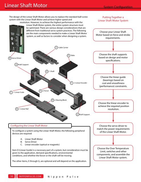
The design of the <strong>Linear</strong> <strong>Shaft</strong> <strong>Motor</strong> allows you to replace the standard ball-screw<br />
system with the <strong>Linear</strong> <strong>Shaft</strong> <strong>Motor</strong> and achieve higher speed and<br />
resolution. However, to achieve the highest performance with the<br />
<strong>Linear</strong> <strong>Shaft</strong> <strong>Motor</strong> system, the entire system structure must<br />
be optimized. There are various design considerations that are<br />
different from traditional servo system practices. The following<br />
are the main components needed to make a <strong>Linear</strong> <strong>Shaft</strong> <strong>Motor</strong><br />
system, as well as factors to consider when designing a system.<br />
Putting Together a<br />
<strong>Linear</strong> <strong>Shaft</strong> <strong>Motor</strong> System<br />
Choose your <strong>Linear</strong> <strong>Shaft</strong><br />
<strong>Motor</strong> based on force and stroke<br />
requirements.<br />
Choose the <strong>Linear</strong> <strong>Shaft</strong> <strong>Motor</strong> Based on Force and Stroke Requirements<br />
For assistance in selecting the correct <strong>Linear</strong> <strong>Shaft</strong> <strong>Motor</strong>, check out Nippon Pulse's “SMART” tool (<strong>Linear</strong> <strong>Shaft</strong> <strong>Motor</strong> Application<br />
Resource Tool) which can be found at nipponpulse.com. The <strong>Linear</strong> <strong>Shaft</strong> <strong>Motor</strong> should be mounted as closely as possible to the<br />
center of gravity of the moving load, and to the working point of the machine.<br />
If the motor and feedback are far apart, the machine structure and linear guide (bearings) must be of sufficient mechanical<br />
stiffness to minimize dynamic deflections of the structure. Be sure to allow clearance for ventilation and access for cleaning,<br />
repair, service and inspections. Ventilation is extremely important. Be sure the area for ventilation is not obstructed, as motors<br />
may get warm, and heat must be dissipated to prevent damage.<br />
F Cable Carrier<br />
Force Range<br />
Usable Stroke Range<br />
B Servo Driver<br />
E <strong>Shaft</strong> Support<br />
A -1 <strong>Shaft</strong><br />
G Table<br />
C -2 <strong>Linear</strong> Encoder<br />
Choose the shaft supports<br />
based on design and motor<br />
specifications.<br />
Choose the linear guide<br />
(bearings) based on<br />
cost and smoothness<br />
(performance) constraints.<br />
Model<br />
S040<br />
S080<br />
S120<br />
S160<br />
S200<br />
L250<br />
S250<br />
L320<br />
S320<br />
S350<br />
L427<br />
S427<br />
S435<br />
S500<br />
S605<br />
0.1 1.0 10.0 100.0 1000.0 10000.0<br />
Force (N)<br />
Rated Force Range Peak Force Range<br />
Model<br />
S040<br />
S080<br />
S120<br />
S160<br />
S200<br />
S250<br />
L250<br />
S320<br />
L320<br />
S350<br />
S427<br />
L427<br />
S435<br />
S500<br />
S605<br />
S1000<br />
0 1000 2000 3000 4000 5000<br />
Usable Stroke (mm)<br />
C -1 <strong>Linear</strong> Scale<br />
D -1 <strong>Linear</strong> Rail<br />
A -2 Forcer<br />
Configuring the <strong>Linear</strong> <strong>Shaft</strong> <strong>Motor</strong><br />
D -2 Bearing Block<br />
E <strong>Shaft</strong> Support<br />
To configure a system using the <strong>Linear</strong> <strong>Shaft</strong> <strong>Motor</strong>, the following peripheral<br />
devices are required:<br />
A. <strong>Linear</strong> <strong>Shaft</strong> <strong>Motor</strong><br />
B. Servo Driver<br />
C. <strong>Linear</strong> encoder (optical or magnetic)<br />
Item D (<strong>Linear</strong> Guide) is a necessary part of a system, but consideration must be<br />
given to the application, demand specifications, environmental<br />
conditions, and whether the forcer or the shaft will be moving.<br />
The other items, E through G, are optional and will depend on the application.<br />
Choose the linear encoder to<br />
achieve the required position<br />
resolution.<br />
Choose the servo driver to<br />
match the power requirements<br />
of the <strong>Linear</strong> <strong>Shaft</strong> <strong>Motor</strong>.<br />
Choose the Over Temperature<br />
Limit, switches and other<br />
components, and assemble the<br />
<strong>Linear</strong> <strong>Shaft</strong> <strong>Motor</strong> system.<br />
Choose the <strong>Shaft</strong> Supports Based on Force<br />
and Stroke Requirements<br />
Select a shaft support as outlined in the data sheet of<br />
your selected <strong>Linear</strong> <strong>Shaft</strong> <strong>Motor</strong>. The shaft support is<br />
what allows longer strokes in a <strong>Linear</strong> <strong>Shaft</strong> <strong>Motor</strong> system<br />
without excessive bending of the shaft. The shaft support<br />
should not only be able to support the mass of the shaft,<br />
but also be in contact with the shaft for the specified<br />
support length. While a single shaft support will provide<br />
better security and<br />
easier alignment,<br />
another option is to<br />
space two smaller<br />
shaft supports for<br />
the specified support<br />
length. The drawing<br />
to the right illustrates<br />
these two different<br />
options.<br />
Choose the <strong>Linear</strong> Guide (Bearings) Based on Smoothness<br />
(Performance) Constraints<br />
The linear guide (bearings) must be selected to support the moving load.<br />
Often, the linear guide is the only moving contact type component in the<br />
system. Therefore, this component requires special attention. Desirable bearing<br />
characteristics include high mechanical stiffness (for increased natural frequency)<br />
and low friction. Because the <strong>Linear</strong> <strong>Shaft</strong> <strong>Motor</strong> can provide high velocities, the<br />
speed and acceleration limitations of the bearings need to be considered. Some<br />
common bearing choices are compared in the table below. Air bearings are most<br />
desirable from the standpoint of smoothness, while mechanical slide rails are<br />
desirable due to portability.<br />
Slide<br />
Rails<br />
Cam<br />
Follower<br />
Crossed<br />
Roller<br />
Recirculating<br />
Element<br />
Travel ¤ ¤ • ¤ £<br />
Stiffness • • ¤ ¤ £<br />
Speed • ¤ £ ◦ £<br />
Smoothness • £ £ ¤ ◦<br />
Precision • • £ £ ◦<br />
Load £ • £ ¤ •<br />
Cost ◦ ◦ £ £ •<br />
Air<br />
Least Desirable • £ ¤ ◦ Most Desirable<br />
10 nipponpulse.com N i p p o n P u l s e<br />
Y o u r P a r t n e r I n M o t i o n C o n t r o l<br />
nipponpulse.com 11