Products (en)

You also want an ePaper? Increase the reach of your titles
YUMPU automatically turns print PDFs into web optimized ePapers that Google loves.
644-19_FIN_loga_RECEPCE__CZ-VLAJKA_120x60cm__TISK.indd 1 05.11.2019 16:38:02<br />
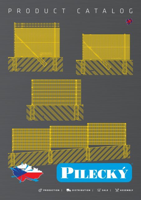
P R O D U C T C A T A L O G<br />
PRAGUE<br />
PRODUCTION | DISTRIBUTION | SALE | ASSEMBLY
Mokrovraty<br />
– firm domicile, warehouses Mokrovraty – warehouse Farma<br />
Mokrovraty – warehouse<br />
Dobříš – warehouse 2<br />
Rybníky – warehouse<br />
Častá<br />
– firm domicile, warehouses
PILECKÝ, s. r. o., your supplier of f<strong>en</strong>ce-systems, has be<strong>en</strong> on the<br />
market since 1994, wh<strong>en</strong> it began manufacturing traditional wire<br />
f<strong>en</strong>ces, which, over time, was ext<strong>en</strong>ded to give today's modern<br />
company with a compreh<strong>en</strong>sive offer of classic and highly customerori<strong>en</strong>ted<br />
types of f<strong>en</strong>ces.<br />
During manufacture and sales, we place great emphasis on high<br />
quality, user-fri<strong>en</strong>dly sales and post-sales services. We can design<br />
your f<strong>en</strong>ce, give you a free price quote, deliver it to your door, erect<br />
it and, of course, <strong>en</strong>sure it is regularly serviced. The vast majority<br />
of your f<strong>en</strong>ce is now in stock. Thanks to our professional approach<br />
and our high commitm<strong>en</strong>t, we are able to back up these words<br />
with actions.<br />
The breadth of our product range includes classic chain link f<strong>en</strong>cing<br />
– IDEAL®, decorative and forestry mesh – DEKORAN®, forest<br />
mesh, IDEAL® posts, IDEAL® gates and gateways. We are the sole<br />
importers of industrial f<strong>en</strong>ces, mesh for animal breeders, forged<br />
f<strong>en</strong>ces, garage doors (overhead, double-swing, sectional, rollershutter)<br />
and all types of gateways.<br />
The f<strong>en</strong>cing systems supplied by our company, backed-up by<br />
our advice and experi<strong>en</strong>ce, are your ideal solution for a quick and<br />
high quality means of <strong>en</strong>suring a border for private land, business<br />
premises, halls, various industrial areas, gard<strong>en</strong>s and orchards,<br />
construction sites and many other buildings.<br />
Call us – we can find an effective solution for you.<br />
Team Pilecky, s. r. o.<br />
“It‘s not <strong>en</strong>ough for us to be good<br />
– we always want to be better”<br />
Zd<strong>en</strong>ek Pilecky<br />
CEO
www.pilecky.cz<br />
Chain link f<strong>en</strong>ces – IDEAL® 6-8<br />
Artificial living f<strong>en</strong>ce, Shielded link 9<br />
THERMOPIL® – Shielding Tape 10-11<br />
BAMBOOPIL – chipped bamboo 12<br />
REEDPIL – reed mat 13<br />
Welded wire mesh – PILONET® 14-15<br />
Decoration mesh – DEKORAN® 16-17<br />
Wicket – ECONOMY® 18-19<br />
Wickets and gates – SOLID® 20-21<br />
Wickets and gates – IDEAL® 22-23<br />
Wickets and gates – PILOFOR® 24-25<br />
Wickets and gates – PILOFOR SUPER® 26-27<br />
Accessory for wickets and gates 28-29<br />
Hexagonal and welded wire netting for breeders 30-31<br />
Posts and post supports 32-33<br />
Accessory for installation of square f<strong>en</strong>cing meshes<br />
and welded meshes<br />
34-35<br />
Base slabs with accessory 36<br />
Under-f<strong>en</strong>ce foil 37<br />
New type of gard<strong>en</strong> paving slab PILHRAB 38-39<br />
Earth screws 40-41<br />
Forest mesh 42-43<br />
Highest protection elem<strong>en</strong>ts 44-45<br />
Industrial welded panels PILOFOR® ECO, LIGHT 46-47<br />
4<br />
Address: Mokrovraty 177 | 262 03 Novy Knin – Czech Republic | Phone: +420 318 593 878 |<br />
Fax: +420 318 593 849 | E-mail: export@pilecky.cz
CONTENT<br />
Industrial welded panels PILOFOR® CLASSIC 48-49<br />
Industrial welded panels PILOFOR® SUPER 50-51<br />
Industrial welded panels PILOFOR® SUPER STRONG 52-53<br />
Mobile f<strong>en</strong>cing 54-55<br />
Garage doors 56-57<br />
Gabion walls – embankm<strong>en</strong>t 58-59<br />
Gabions 60-61<br />
Gabions to order 62-63<br />
PILWOOD® f<strong>en</strong>ce boards 64-65<br />
WPC Terrace 66-67<br />
Aluminium F<strong>en</strong>cing – ALUPIL® 68-69<br />
Accessories for metal f<strong>en</strong>ces 70<br />
ASSEMBLY INSTRUCTIONS 71<br />
Instructions for assembling chain link f<strong>en</strong>ces IDEAL® 72-73<br />
Instructions for assembling welded wire nettings PILONET® 74-75<br />
Installation instructions for BENITA® 76-77<br />
Installation instructions for knotted f<strong>en</strong>cing mesh<br />
LIGHT, STANDARD, PREMIUM<br />
Instructions for assembling PILOFOR® panels<br />
on round posts IDEAL®<br />
Instructions for assembling PILOFOR® welded panels<br />
on square posts 60 × 60 mm<br />
Instructions for assembling PILOFOR® welded panels<br />
on rectangular posts PILODEL® 60 × 40 mm<br />
78-79<br />
80-81<br />
82-83<br />
84-85<br />
Instructions for mounting Gabion walls – embankm<strong>en</strong>t 86-87<br />
Instructions for mounting PILWOOD® f<strong>en</strong>ce boards 88-89<br />
www.pilecky.cz 5
QUALITY<br />
BRAND<br />
www.pilecky.cz<br />
Chain link f<strong>en</strong>ces – IDEAL ®<br />
• high quality f<strong>en</strong>ces made of steel wires with galvanized or galvanized + PVC finish<br />
• round galvanized or galvanized + PVC posts with cap and t<strong>en</strong>sion wire clamp are recomm<strong>en</strong>ded to be used for the assembly<br />
• it is also recomm<strong>en</strong>ded to use t<strong>en</strong>sion wires, binding wires, stretchers and posts with the same galvanized or galvanized + PVC finish<br />
IDEAL ® galvanized + PVC 50<br />
description<br />
eyelets 55 × 55 mm<br />
wire diameter 2,50 mm<br />
15, 25 m long compact roll<br />
RAL 6005 – gre<strong>en</strong>,<br />
RAL 8014 – brown<br />
RAL 7016 – anthracite<br />
(t<strong>en</strong>sion wire not included;<br />
must be ordered separately)<br />
Note: colour white, blue, grey<br />
– price on request.<br />
color<br />
height roll l<strong>en</strong>gth<br />
(mm) (m)<br />
gre<strong>en</strong> 1000 15<br />
gre<strong>en</strong> 1000 25<br />
brown 1000 25<br />
anthracite 1000 25<br />
gre<strong>en</strong> 1250 15<br />
gre<strong>en</strong> 1250 25<br />
brown 1250 25<br />
anthracite 1250 25<br />
gre<strong>en</strong> 1500 15<br />
gre<strong>en</strong> 1500 25<br />
brown 1500 25<br />
anthracite 1500 25<br />
gre<strong>en</strong> 1600 15<br />
gre<strong>en</strong> 1600 25<br />
brown 1600 25<br />
anthracite 1600 25<br />
gre<strong>en</strong> 1800 15<br />
gre<strong>en</strong> 1800 25<br />
brown 1800 25<br />
anthracite 1800 25<br />
gre<strong>en</strong> 2000 15<br />
gre<strong>en</strong> 2000 25<br />
brown 2000 25<br />
anthracite 2000 25<br />
IDEAL ® galvanized + PVC 50 – SUPER<br />
description<br />
IDEAL ® galvanized<br />
description<br />
eyelets 55 × 55 mm<br />
wire diameter 3,00 mm<br />
25 m long compact roll<br />
RAL 6005 – gre<strong>en</strong><br />
(t<strong>en</strong>sion wire not included;<br />
must be ordered separately)<br />
eyelets 55 × 55 mm<br />
wire diameter 2,00 mm<br />
25 m long compact roll<br />
(t<strong>en</strong>sion wire not included;<br />
must be ordered separately)<br />
height<br />
(mm)<br />
1000<br />
1250<br />
1500<br />
1600<br />
1800<br />
2000<br />
height<br />
(mm)<br />
1000<br />
1250<br />
1500<br />
1600<br />
1800<br />
2000<br />
USE: gard<strong>en</strong>s, factories and warehouses...<br />
IDEAL ® galvanized + PVC – round non-interlaced roll<br />
description<br />
eyelets 55 × 55 mm<br />
wire diameter 2,50 mm<br />
RAL 6005 – gre<strong>en</strong> 15, 25 m long<br />
RAL 7016 – anthracite 25 m long<br />
(including t<strong>en</strong>sion wire)<br />
* from a height of 1500 mm,<br />
it is recomm<strong>en</strong>ded to add<br />
a c<strong>en</strong>ter t<strong>en</strong>sioning wire<br />
(not included in the package)<br />
color<br />
height<br />
(mm)<br />
roll l<strong>en</strong>gth<br />
(m)<br />
gre<strong>en</strong> 1000 15<br />
gre<strong>en</strong> 1000 25<br />
anthracite 1000 25<br />
gre<strong>en</strong> 1250 15<br />
gre<strong>en</strong> 1250 25<br />
anthracite 1250 25<br />
gre<strong>en</strong> 1500* 15<br />
gre<strong>en</strong> 1500* 25<br />
anthracite 1500* 25<br />
gre<strong>en</strong> 1600* 15<br />
gre<strong>en</strong> 1600* 25<br />
anthracite 1600* 25<br />
gre<strong>en</strong> 1800* 15<br />
gre<strong>en</strong> 1800* 25<br />
anthracite 1800* 25<br />
gre<strong>en</strong> 2000* 15<br />
gre<strong>en</strong> 2000* 25<br />
anthracite 2000* 25<br />
IDEAL ® galvanized – round interlaced roll<br />
description<br />
NEW<br />
NEW<br />
NEW<br />
NEW<br />
NEW<br />
NEW<br />
eyelets 55 × 55 mm<br />
wire diameter 2,00 mm<br />
15 and 25 m long roll<br />
(including t<strong>en</strong>sion wire)<br />
* from a height of 1500 mm,<br />
it is recomm<strong>en</strong>ded to add<br />
a c<strong>en</strong>ter t<strong>en</strong>sioning wire<br />
(not included in the package)<br />
height<br />
(mm)<br />
roll l<strong>en</strong>gth<br />
(m)<br />
1000 15<br />
1000 25<br />
1250 15<br />
1250 25<br />
1500* 15<br />
1500* 25<br />
1600* 15<br />
1600* 25<br />
1800* 15<br />
1800* 25<br />
2000* 15<br />
2000* 25<br />
6<br />
Address: Mokrovraty 177 | 262 03 Novy Knin – Czech Republic | Phone: +420 318 593 878 |<br />
Fax: +420 318 593 849 | E-mail: export@pilecky.cz
IDEAL ® galvanized + PVC 45 – TENNIS<br />
• offer for f<strong>en</strong>cing of court to height 3,0; 3,5; 4,0 m<br />
• f<strong>en</strong>cing mesh in rolls according to standard dim<strong>en</strong>sions<br />
of court (18 × 36 m), i.e. roll at 18 meters<br />
description<br />
eyelets 45 × 45 mm<br />
wire diameter 1,80/2,70 mm<br />
RAL 6005 – gre<strong>en</strong><br />
height<br />
(mm)<br />
roll l<strong>en</strong>gth<br />
(m)<br />
3000 18<br />
3500 18<br />
T<strong>en</strong>sion wire IDEAL ® galvanized + PVC<br />
description color l<strong>en</strong>gth (m)<br />
roll 26, 52 and 78 m<br />
wire diameter 3,40 mm<br />
RAL 6005 – gre<strong>en</strong><br />
RAL 8014 – brown<br />
RAL 7016 – anthracite<br />
gre<strong>en</strong><br />
gre<strong>en</strong><br />
gre<strong>en</strong><br />
brown<br />
26 (gre<strong>en</strong> label)<br />
52 (white label)<br />
78 (gre<strong>en</strong> label)<br />
52 (white label)<br />
4000 18<br />
brown<br />
78 (gre<strong>en</strong> label)<br />
anthracite<br />
52 (white label)<br />
Posts and post supports IDEAL ®<br />
galvanized + PVC – TENNIS<br />
description<br />
round posts IDEAL ®<br />
RAL 6005 – gre<strong>en</strong><br />
post includes the plastic cap<br />
(no clamp for t<strong>en</strong>sioning wire)<br />
height<br />
(mm)<br />
diameter<br />
(mm)<br />
3750 60<br />
4300 60<br />
anthracite<br />
78 (gre<strong>en</strong> label)<br />
4900 60<br />
5200 60<br />
post supports IDEAL ®<br />
RAL 6005 – gre<strong>en</strong><br />
including plastic cap<br />
and fast<strong>en</strong>ers<br />
3500 48<br />
4000 48<br />
4750 48<br />
T<strong>en</strong>sion wire galvanized<br />
description<br />
l<strong>en</strong>gth (m)<br />
Wicket IDEAL ® galvanized + PVC – TENNIS<br />
description<br />
wicket IDEAL® TENNIS for t<strong>en</strong>nis courts<br />
RAL 6005 – gre<strong>en</strong><br />
frame made of round sections (closed)<br />
square mesh paneling<br />
eyelets 45 × 45 mm<br />
wire diameter 2,70 mm<br />
wicket consists of 2 posts, including pivot hinges<br />
includeda is the lock with FAB lock insert<br />
height<br />
(mm)<br />
width<br />
(mm)<br />
2200 1250<br />
roll 52 and 78 m<br />
wire diameter 3,00 mm<br />
52 (white label)<br />
78 (gre<strong>en</strong> label)<br />
FIVE-STAGE PROTECTION<br />
OF FRAME AND POSTS:<br />
degreasing<br />
phosphating<br />
demineralized water rinse 3×<br />
passivation<br />
(Envirox “SG” process)<br />
polymer paint<br />
layer 80 μm<br />
steel elem<strong>en</strong>t<br />
zinc layer<br />
RECOMMENDATION:<br />
• no c<strong>en</strong>ter t<strong>en</strong>sion wire technologically<br />
possible to interlock during production<br />
and must be stretched indep<strong>en</strong>d<strong>en</strong>tly<br />
• c<strong>en</strong>ter t<strong>en</strong>sion wire is included with<br />
meshes with height beginning at 1,5 m<br />
www.pilecky.cz 7
Accessories for the installation of chain link f<strong>en</strong>ces<br />
description<br />
t<strong>en</strong>sioner with galvanized finish<br />
Binding wires<br />
description<br />
wire thickness<br />
(mm)<br />
l<strong>en</strong>gth<br />
(m)<br />
galvanized binding wire in wired case 1,0 100<br />
t<strong>en</strong>sioner with galvanized<br />
+ PVC finish<br />
RAL 6005 – gre<strong>en</strong><br />
RAL 8014 – brown<br />
RAL 9010 – white<br />
RAL 5010 – blue<br />
RAL 7016 – anthracite<br />
gre<strong>en</strong><br />
brown<br />
1,2 100<br />
galvanized binding wire 1,0 24<br />
white<br />
1,4 50<br />
1,8 50<br />
blue<br />
galvanized + PVC RAL 6005 binding wire<br />
in wired case – gre<strong>en</strong><br />
1,4 60<br />
t<strong>en</strong>sioner SUPER<br />
with galvanized + PVC finish – gre<strong>en</strong><br />
anthracite<br />
binding wire galvanized + PVC RAL 6005<br />
with cutoff, flat – gre<strong>en</strong><br />
– 100<br />
binding wire + PVC RAL 6005 – gre<strong>en</strong> 1,4 24<br />
KOMBI galvanized t<strong>en</strong>sioner<br />
KOMBI galvanized + PVC t<strong>en</strong>sioner<br />
binding wire galvanized + PVC<br />
RAL 6005 – gre<strong>en</strong><br />
RAL 8014 – brown<br />
RAL 9010 – white<br />
RAL 7016 – anthracite<br />
1,4 50<br />
1,4 50<br />
t<strong>en</strong>sion comb IDEAL® for stretching square meshes<br />
having heights up to 1500 mm (in primer coat)<br />
1,4 50<br />
1,4 50<br />
t<strong>en</strong>sion comb IDEAL® for stretching square meshes<br />
having heights above 1500 mm (in primer coat)<br />
binding wire galvanized + PVC – gre<strong>en</strong> 2,6 25<br />
pliers IDEAL ® PROFI<br />
brace IDEAL ® galvanized<br />
binding wire galvanized 0,65 –<br />
brace IDEAL ® galvanized<br />
binding wire galvanized<br />
and varnished RAL 6005 - gre<strong>en</strong> 0,65 –<br />
brace IDEAL ® galvanized + PVC RAL 6005 – gre<strong>en</strong><br />
brace IDEAL ® galvanized + PVC RAL 6005 – gre<strong>en</strong><br />
binding wire galvanized<br />
(2 pcs in package) 0,65 –<br />
brace IDEAL ® galvanized + PVC RAL 7016 – anthracite<br />
brace IDEAL ® galvanized + PVC RAL 7016 – anthracite<br />
binding wire galvanized and varnished<br />
RAL 6005<br />
(2 pcs in package)<br />
0,65 –<br />
8<br />
Address: Mokrovraty 177 | 262 03 Novy Knin – Czech Republic | Phone: +420 318 593 878 |<br />
Fax: +420 318 593 849 | E-mail: export@pilecky.cz
QUALITY<br />
BRAND<br />
www.pilecky.cz<br />
Artificial living f<strong>en</strong>ce<br />
Artificial “living f<strong>en</strong>ce”<br />
description<br />
replaces the living f<strong>en</strong>ce<br />
package contains 3 bm<br />
95% non-transpar<strong>en</strong>cy<br />
height<br />
(mm)<br />
1000<br />
1500<br />
• almost non-transpar<strong>en</strong>t<br />
shielding<br />
• very similar to living f<strong>en</strong>ce<br />
with shrubs<br />
• maintains color<br />
• load carrying<br />
shield part<br />
is the knitted<br />
wires in which<br />
h<br />
two-color strips<br />
are applied to imitate<br />
shrub leaves<br />
Shielded link<br />
Shielded knitwear for 70% non-transpar<strong>en</strong>cy<br />
height<br />
(mm)<br />
l<strong>en</strong>gth<br />
(m)<br />
gre<strong>en</strong><br />
1500 25<br />
1600 25<br />
1800 25<br />
2000 25<br />
Shielded knitwear for 90% non-transpar<strong>en</strong>cy<br />
height<br />
(mm)<br />
l<strong>en</strong>gth<br />
(m)<br />
dark gre<strong>en</strong><br />
1500 25<br />
1600 25<br />
1800 25<br />
2000 25<br />
Accessories<br />
PILOFOR® clip for fast<strong>en</strong>ing<br />
mesh scre<strong>en</strong> to f<strong>en</strong>ce panels<br />
with 50 mm eyelet<br />
www.pilecky.cz 9
QUALITY<br />
BRAND<br />
www.pilecky.cz<br />
ONLY WHILE<br />
STOCKS LAST<br />
THERMOPIL ® – Shielding Tape<br />
The THERMOPIL® Shielding Tape for 2.5 m wide panels with 5 and 20 cm wire spacing<br />
is an excell<strong>en</strong>t solution for the shielding of panel f<strong>en</strong>cing and of quadrilateral mesh.<br />
It creates a feeling of privacy throughout the year. The tape is made of polyethyl<strong>en</strong>e,<br />
a material that is used to pack food. Splitting is possible in all directions.<br />
HIGH STRENGTH<br />
UV<br />
HIGH RESISTANCE<br />
product description colour height (cm) l<strong>en</strong>gth (m) EAN<br />
THERMOPIL CLASSIC (4,75/50) gre<strong>en</strong> 4,75 50 8595068451687<br />
THERMOPIL CLASSIC (19/2,55) gre<strong>en</strong> 19 2,55 8595068452875<br />
THERMOPIL CLASSIC (19/2,55) anthracite 19 2,55 8595068452882<br />
THERMOPIL TECHNO 1 (19/26) gre<strong>en</strong> 19 26 8595068451717<br />
THERMOPIL TECHNO 1 (19/26) anthracite 19 26 8595068451724<br />
THERMOPIL TECHNO 2 (19/26) gre<strong>en</strong> 19 26 8595068451731<br />
THERMOPIL TECHNO 2 (19/26) anthracite 19 26 8595068451748<br />
10<br />
Address: Mokrovraty 177 | 262 03 Novy Knin – Czech Republic | Phone: +420 318 593 878 |<br />
Fax: +420 318 593 849 | E-mail: export@pilecky.cz
CLASSIC<br />
CLASSIC<br />
TECHNO 1<br />
TECHNO 2<br />
colour height (cm) l<strong>en</strong>gth (m)<br />
colour height (cm) l<strong>en</strong>gth (m)<br />
colour height (cm) l<strong>en</strong>gth (m)<br />
colour height (cm) l<strong>en</strong>gth (m)<br />
GREEN<br />
RAL 6005 4,75 50<br />
GREEN<br />
RAL 6005<br />
ANTHRACIT<br />
RAL 7016<br />
19 2,55<br />
GREEN<br />
RAL 6005<br />
ANTHRACIT<br />
RAL 7016<br />
19 26<br />
GREEN<br />
RAL 6005<br />
ANTHRACIT<br />
RAL 7016<br />
19 26<br />
Accessory for installationtion<br />
description colour package (pcs)<br />
THERMOPIL clip gre<strong>en</strong> 10<br />
anthracit 10<br />
SPRING SUMMER AUTUMN WINTER<br />
www.pilecky.cz 11
QUALITY<br />
BRAND<br />
www.pilecky.cz<br />
BAMBOOPIL – chipped bamboo<br />
Bamboo is a natural material designed to increase your privacy. It is also suitable as protection<br />
against noise dust and wind. The bamboo is dried and tied with a binding wire, which str<strong>en</strong>gth<strong>en</strong>s<br />
it allows th<strong>en</strong> the bamboo to be used as a shade on the f<strong>en</strong>ce.<br />
Chopped bamboo can also be painted, varnished and is more durable and stronger than a reed mat.<br />
Lifespan: 4 to 7 years.<br />
description<br />
95% non-transpar<strong>en</strong>cy<br />
height<br />
(mm)<br />
l<strong>en</strong>gth<br />
(m)<br />
package<br />
(pcs)<br />
100 5 1<br />
150 5 1<br />
200 5 1<br />
12<br />
Address: Mokrovraty 177 | 262 03 Novy Knin – Czech Republic | Phone: +420 318 593 878 |<br />
Fax: +420 318 593 849 | E-mail: export@pilecky.cz
QUALITY<br />
BRAND<br />
www.pilecky.cz<br />
REEDPIL – reed mat<br />
Reed is a natural material designed to increase your privacy - in a pergola or in the gard<strong>en</strong>. It is also<br />
suitable as protection against noise dust and wind. The reed is dried and tied with a binding wire,<br />
which functions as reinforcem<strong>en</strong>t and allows its use as a shading on the f<strong>en</strong>ce.<br />
Reed is a material that is very malleable but also fragile at the same time. Over time, the material<br />
turns black. It is not a defect of the material. It is because the material is natural and therefore<br />
changes in sunlight.<br />
description<br />
95% non-transpar<strong>en</strong>cy<br />
height<br />
(mm)<br />
l<strong>en</strong>gth<br />
(m)<br />
package<br />
(pcs)<br />
100 5 1<br />
150 5 1<br />
200 5 1<br />
www.pilecky.cz 13
QUALITY<br />
BRAND<br />
www.pilecky.cz<br />
Welded wire mesh – PILONET ®<br />
• galvanized + PVC<br />
• strongly galvanized steel wires<br />
• 25 m long roll<br />
• gre<strong>en</strong> RAL 6005,<br />
anthracite RAL 7016<br />
GARDEN WIRE MESH<br />
description<br />
PILONET ® LIGHT PLUS<br />
eyelets 75 × 100 mm<br />
wire diameter 2,10 mm<br />
roll l<strong>en</strong>gth<br />
(m)<br />
height<br />
(mm)<br />
25 1000<br />
25 1200<br />
25 1500<br />
description<br />
PILONET ® ANTHRACITE<br />
eyelets 50 × 100 mm<br />
wire diameter 2,50 mm<br />
roll l<strong>en</strong>gth<br />
(m)<br />
height<br />
(mm)<br />
25 1000<br />
25 1200<br />
25 1500<br />
25 1800<br />
25 2000<br />
PILONET ® MIDDLE<br />
galvanized + PVC<br />
eyelets 50 × 100 mm<br />
wire diameter 2,20 mm<br />
for heights of 600-1500 mm<br />
wire diameter 2,50 mm<br />
for heights of 1800-2000 mm<br />
* not compatible with 25 m<br />
wound product<br />
10 400*<br />
10 600*<br />
10 800*<br />
10 1000*<br />
25 600<br />
25 800<br />
25 1000<br />
25 1200<br />
25 1500<br />
25 1800<br />
25 2000<br />
PILONET ® HEAVY<br />
eyelets 50 × 50 mm<br />
wire diameter 2,50 mm<br />
25 1000<br />
25 1200<br />
25 1500<br />
25 1800<br />
25 2000<br />
USE: private gard<strong>en</strong>s, parks, schools...<br />
14<br />
Address: Mokrovraty 177 | 262 03 Novy Knin – Czech Republic | Phone: +420 318 593 878 |<br />
Fax: +420 318 593 849 | E-mail: export@pilecky.cz
INDUSTRIAL WIRE MESH<br />
• galvanized + PVC<br />
• strongly galvanized steel wires<br />
• 25 m long roll<br />
• gre<strong>en</strong><br />
description<br />
PILONET ® SUPER<br />
eyelets 50 × 50 mm<br />
wire diameter 3,00 mm<br />
roll l<strong>en</strong>gth<br />
(m)<br />
height<br />
(mm)<br />
25 1000<br />
25 1200<br />
25 1500<br />
25 1800<br />
25 2000<br />
Accessory for installation of welded meshes<br />
description<br />
package (pcs)<br />
clamps PILCLIP® made of stainless steel 250<br />
wire for fast<strong>en</strong>ing of mesh to posts<br />
wire diameter 3,5 mm<br />
500<br />
• each horizontal wire is waved<br />
to drain water<br />
• each horizontal wire is a t<strong>en</strong>sion wire<br />
• edge wires are doubled to increase e<br />
the str<strong>en</strong>gth of the net<br />
• the superior posts for the PILONET®<br />
system are those with the PILCLIP® P®<br />
assembly strip, which have a profile<br />
on the surface for anchoring mesh<br />
• the PILONET® system can be supplem<strong>en</strong>ted with<br />
a wide variety of high-level single swing gates,<br />
gateways and sliding gates<br />
• service life of 10 years guaranteed<br />
pliers for clamps PILCLIP® for installation<br />
of the meshes to posts<br />
can be r<strong>en</strong>ted, price: 0 EUR, returnable deposit charge<br />
creping pliers for PILONET® meshes 1<br />
can be r<strong>en</strong>ted, price: 0 EUR, returnable deposit charge<br />
t<strong>en</strong>sioning comb for<br />
1200 mm 1<br />
t<strong>en</strong>sioning of welded meshes<br />
(in primer coat)<br />
1500 mm 1<br />
can be r<strong>en</strong>ted, price: 0 EUR, returnable deposit charge<br />
plastic t<strong>en</strong>sioning comb for manual<br />
t<strong>en</strong>sioning of welded meshes<br />
1<br />
1<br />
USE: sports stadiums, industrial buildings, public areas, factories and warehouses...<br />
www.pilecky.cz 15
QUALITY<br />
BRAND<br />
www.pilecky.cz<br />
Decoration mesh – DEKORAN ®<br />
description<br />
height (mm)<br />
description<br />
height (mm)<br />
DEKORAN ®<br />
knitted mesh with arc <strong>en</strong>ding<br />
eyelets 90 × 150 mm<br />
diameter of wires:<br />
horizontal 2,50 mm<br />
vertical 3,00 mm<br />
RAL 6005 – gre<strong>en</strong><br />
250<br />
400<br />
650<br />
DEKORAN ®<br />
knitted mesh with arc <strong>en</strong>ding<br />
eyelets 90 × 150 mm<br />
diameter of wires:<br />
horizontal 2,50 mm<br />
vertical 3,00 mm<br />
RAL 6005 – gre<strong>en</strong><br />
250<br />
400<br />
650<br />
10 m rolls<br />
900<br />
25 m rolls<br />
900<br />
1200<br />
USE: f<strong>en</strong>ces for shrubs, patches, parks and sidewalks...<br />
16<br />
Address: Mokrovraty 177 | 262 03 Novy Knin – Czech Republic | Phone: +420 318 593 878 |<br />
Fax: +420 318 593 849 | E-mail: export@pilecky.cz
Posts for decoration meshes<br />
description<br />
metal post with PVC<br />
the post includes a cap with<br />
eyelet for the<br />
guiding wire<br />
RAL 6005 – gre<strong>en</strong><br />
height/diameter<br />
(mm)<br />
700/16<br />
1000/20<br />
1200/20<br />
• elegant knitted gard<strong>en</strong> f<strong>en</strong>ce<br />
• horizontal wires are alternatively knitted<br />
• ideal solution for flower beds<br />
• easy installation<br />
www.pilecky.cz 17
QUALITY<br />
BRAND<br />
www.pilecky.cz<br />
Wicket – ECONOMY ®<br />
• surface finish: galvanized + PVC (RAL 6005 - gre<strong>en</strong>)<br />
• frame made of round sections (closed)<br />
• welded mesh paneling<br />
• mesh size 50 × 100 mm<br />
• wire diameter 3,50 mm<br />
• wicket consists of 2 posts, including adjustable hinges<br />
• flap lockable with padlock is included (padlock is not part of delivery)<br />
RECOMMENDED<br />
R E C O M M E N D E D<br />
wicket width* × height<br />
(mm)<br />
SINGLE-WING WICKET<br />
height of posts / diameter<br />
(mm)<br />
galvanized<br />
+ PVC<br />
1078 × 1000 1500 / 48 <br />
1078 × 1200 1750 / 48 <br />
1078 × 1500 2000 / 48 <br />
• high resistance of paneling<br />
• simple installation<br />
• universal design (left, right)<br />
• safety<br />
• unrivaled pricing<br />
* width at post middle<br />
Wicket<br />
with paneling,<br />
which never will be<br />
surpassed!<br />
18<br />
Address: Mokrovraty 177 | 262 03 Novy Knin – Czech Republic | Phone: +420 318 593 878 |<br />
Fax: +420 318 593 849 | E-mail: export@pilecky.cz
Single-wing wicket – ECONOMY ®<br />
A<br />
B<br />
1078 mm (doporuč<strong>en</strong>á minimální šířka)<br />
1078 mm (recomm<strong>en</strong>ded minimum width)<br />
We recomm<strong>en</strong>d using the supporting<br />
struts to secure the position of the<br />
wicket posts, in order to <strong>en</strong>sure higher<br />
stability and safety.<br />
A. Adjustable hinge<br />
B. Flap<br />
www.pilecky.cz 19
QUALITY<br />
BRAND<br />
www.pilecky.cz<br />
Wickets and gates – SOLID ®<br />
• surface finish: galvanized + PVC (RAL 6005 - gre<strong>en</strong>)<br />
• frame made of round sections (closed)<br />
• welded mesh paneling<br />
• mesh size 50 × 100 mm<br />
• wire diameter 3,50 mm<br />
• wicket consists of 2 posts, including adjustable hinges<br />
• latch lock, plastic handle and metal <strong>en</strong>d stop of the wicket<br />
are part of the delivery<br />
Now I will not<br />
miss ev<strong>en</strong> one!<br />
wicket width* × height<br />
(mm)<br />
SINGLE-WING WICKET<br />
height of posts / diameter<br />
(mm)<br />
galvanized<br />
+ PVC<br />
1073 × 950 1500 / 48 <br />
1073 × 1200 1750 / 48 <br />
1073 × 1450 2000 / 48 <br />
1085 × 1750 2300 / 60 <br />
1085 × 1950 2500 / 60 <br />
* width at post middle<br />
Double-wing gate – SOLID ®<br />
with steel lugs for padlock<br />
• surface finish: galvanized + PVC (RAL 6005 - gre<strong>en</strong>)<br />
• frame made of round sections (closed)<br />
• welded mesh paneling<br />
• mesh size 50 × 100 mm<br />
• wire diameter 3,50 mm<br />
• wicket consists of 2 posts, including<br />
adjustable hinges<br />
• gate locking with padlock<br />
(not part of delivery) in metal lugs<br />
RECOMMENDED<br />
R E C O M M E N D E D<br />
gate width * × height<br />
(mm)<br />
DOUBLE-WING GATE<br />
height of posts /<br />
diameter (mm)<br />
galvanized<br />
+ PVC<br />
3580 × 950 1600 / 60 <br />
3580 × 1200 1850 / 60 <br />
3580 × 1450 2100 / 76 <br />
3580 × 1750 2400 / 76 <br />
3580 × 1950 2600 / 76 <br />
Set of accessories<br />
for double swing gate IDEAL® – UNIVERSAL<br />
package cont<strong>en</strong>ts<br />
– wicket lock with stainless steel part<br />
– insert 47 - IDEAL, PILGATE (23,5/23,5)<br />
– plastic cover for insert, black for round profile<br />
– aluminium handle for round profile, black<br />
– gate stop IDEAL®<br />
* width at post middle<br />
DOUBLE SWING GATE IS MADE FOR UNIVERSAL USE. Locking the double swing gate through eylets can be changed for full-featured<br />
locking system IDEAL® – UNIVERSAL (wicket lock with stainless steel part, insert 47 (23,5/23,5), plastic cover for insert, aluminium handle<br />
for round profile, gate stop IDEAL®). Set is sold separately and it is not part of the double swing gate package.<br />
20<br />
Address: Mokrovraty 177 | 262 03 Novy Knin – Czech Republic | Phone: +420 318 593 878 |<br />
Fax: +420 318 593 849 | E-mail: export@pilecky.cz
Single-wing wicket – SOLID ®<br />
A<br />
B<br />
1073 mm (recomm<strong>en</strong>ded minimum width<br />
1073 mm (doporuč<strong>en</strong>á minimální šířka<br />
pro výšky 950, 1200, 1450)<br />
for heights 950, 1200, 1450)<br />
1085 mm (recomm<strong>en</strong>ded minimum width<br />
1085 mm (doporuč<strong>en</strong>á minimální šířka<br />
We recomm<strong>en</strong>d using the supporting<br />
struts to secure the position of the<br />
wicket posts, in order to <strong>en</strong>sure higher<br />
stability and safety.<br />
for heights 1750, 1950)<br />
pro výšky 1750, 1950)<br />
A. Adjustable hinge<br />
B. Handle, lock and <strong>en</strong>d stop assembly<br />
Double-wing gate – SOLID ®<br />
A<br />
Accessories for locking double swing gate with padlock<br />
(padlock is not included).<br />
Optional accessories IDEAL® – UNIVERSAL (handle, lock, insert, stop).<br />
Set is available in sale separately and it is not part of the gate package.<br />
D<br />
C<br />
3580 mm (recomm<strong>en</strong>ded minimum width)<br />
3605 mm (doporuč<strong>en</strong>á minimální šířka)<br />
B<br />
A. Adjustable hinge<br />
B. C<strong>en</strong>tral door latch with <strong>en</strong>d stop<br />
C. Accessories for locking double swing gate with<br />
padlock (padlock is not included)<br />
D. Optional accessories IDEAL® – UNIVERSAL<br />
(handle, lock, insert, stop).<br />
Set is available in sale separately and it is not<br />
part of the gate package.<br />
www.pilecky.cz 21
QUALITY<br />
BRAND<br />
www.pilecky.cz<br />
Wickets and gates – IDEAL ®<br />
Single-wing wicket – IDEAL ® with lock and cylinder lock insert<br />
• surface finish: galvanized + PVC (RAL 6005 – gre<strong>en</strong>, RAL 7016 – anthracite)<br />
• frame made of round sections (closed)<br />
• square mesh paneling<br />
• mesh size 55 × 55 mm<br />
• wire diameter 2,50 mm<br />
• wicket consists of 2 posts, including adjustable pivot hinges<br />
• wicket is delivered with lock and lock insert installed in wing frame<br />
SINGLE-WING WICKET<br />
MANUFACTURE OF GATES AND WICKETS<br />
IDEAL ®<br />
IN NON-STANDARD DIMENSIONS<br />
MADE TO ORDER<br />
wicket width * height of posts / galvanized + PVC galvanized + PVC<br />
× height (mm) diameter (mm) RAL 6005 RAL 7016<br />
1085 × 950 1600 / 60 <br />
1085 × 1200 1850 / 60 <br />
1085 × 1450 2100 / 60 <br />
1085 × 1550 2200 / 60 <br />
1085 × 1750 2400 / 60 <br />
1085 × 1950 2600 / 60 <br />
* width at post middle<br />
FIVE-STAGE PROTECTION<br />
OF FRAME AND POSTS:<br />
degreasing<br />
phosphating<br />
demineralized water rinse 3×<br />
passivation<br />
(Envirox “SG” process)<br />
polymer paint<br />
layer 80 μm<br />
steel elem<strong>en</strong>t<br />
zinc layer<br />
14 days delivery time<br />
Double-wing gate – IDEAL ® II.<br />
with steel lugs for padlock<br />
• surface finish: galvanized + PVC<br />
(RAL 6005 – gre<strong>en</strong>, RAL 7016 – anthracite)<br />
• frame made of round sections (closed)<br />
• square mesh paneling<br />
• mesh size 55 × 55 mm<br />
• wire diameter 2,50 mm<br />
• gate consists of 2 posts, including<br />
adjustable pivot hinges<br />
• gate locking with padlock<br />
(not part of delivery) in metal lugs<br />
DOUBLE-WING GATE<br />
14 days delivery time<br />
gate width *<br />
× height<br />
(mm)<br />
height of<br />
posts/diameter<br />
(mm)<br />
galvanized<br />
+ PVC<br />
RAL 6005<br />
gate width *<br />
× height<br />
(mm)<br />
height of<br />
posts/diameter<br />
(mm)<br />
galvanized<br />
+ PVC<br />
RAL 6005<br />
galvanized<br />
+ PVC<br />
RAL 7016<br />
gate width *<br />
× height<br />
(mm)<br />
height of<br />
posts/diameter<br />
(mm)<br />
galvanized<br />
+ PVC<br />
RAL 6005<br />
3021 × 950 1600/60 3605 × 950 1600/60 4037 × 950 1600/76 <br />
3021 × 1200 1850/60 3605 × 1200 1850/60 4037 × 1200 1850/76 <br />
3037 × 1450 2100/76 3605 × 1450 2100/76 4037 × 1450 2100/76 <br />
3037 × 1550 2200/76 3605 × 1550 2200/76 4037 × 1550 2200/76 <br />
3037 × 1750 2400/76 3605 × 1750 2400/76 4037 × 1750 2400/76 <br />
3037 × 1950 2600/76 3605 × 1950 2600/76 4037 × 1950 2600/76 <br />
* width at post middle<br />
DOUBLE SWING GATE IS MADE FOR UNIVERSAL USE. Locking the double swing gate through eylets can be changed for full-featured locking<br />
system IDEAL® – UNIVERSAL (wicket lock with stainless steel part, insert 47 (23,5/23,5), plastic cover for insert, aluminium handle for round<br />
profile, gate stop IDEAL®). Set is sold separately and it is not part of the double swing gate package.<br />
22<br />
Address: Mokrovraty 177 | 262 03 Novy Knin – Czech Republic | Phone: +420 318 593 878 |<br />
Fax: +420 318 593 849 | E-mail: export@pilecky.cz
Set of accessories for double swing gate IDEAL® – UNIVERSAL<br />
14 days delivery time<br />
package cont<strong>en</strong>ts<br />
wicket lock with stainless steel part, insert 47 (23,5/23,5), plastic<br />
cover for insert – black for round profile, aluminium handle for<br />
round profile – black, gate stop (RAL 6005 – gre<strong>en</strong>)<br />
wicket lock with stainless steel part, insert 47 (23,5/23,5), plastic<br />
cover for insert – black for round profile, aluminium handle for<br />
round profile – black, gate stop (RAL 7016 – anthracite)<br />
Single-wing wicket – IDEAL ®<br />
A<br />
B<br />
(recomm<strong>en</strong>ded minimum width)<br />
1085 mm (doporuč<strong>en</strong>á minimální šířka)<br />
1085 mm<br />
A. Adjustable hinge<br />
B. Handle, lock and <strong>en</strong>d stop assembly<br />
Double-wing gate – IDEAL ® II.<br />
A<br />
Accessories for locking double swing gate with padlock<br />
(padlock is not included).<br />
Optional accessories IDEAL® – UNIVERSAL (handle, lock, insert, stop).<br />
Set is available in sale separately and it is not part of the gate package.<br />
D<br />
C<br />
3021, 3037, 3605, 4037 mm (recomm<strong>en</strong>ded minimum width)<br />
B<br />
A. Adjustable hinge<br />
B. C<strong>en</strong>tral door latch with <strong>en</strong>d stop<br />
C. Accessories for locking double swing gate with<br />
padlock (padlock is not included)<br />
D. Optional accessories IDEAL® – UNIVERSAL<br />
(handle, lock, insert, stop). Set is available in sale<br />
separately and it is not part of the gate package.<br />
www.pilecky.cz 23
QUALITY<br />
BRAND<br />
www.pilecky.cz<br />
Wickets and gates – PILOFOR ®<br />
Single-wing wicket – PILOFOR ®<br />
• surface finish: galvanized, galvanized + PVC<br />
(RAL 6005 - gre<strong>en</strong>), 2× topcoat<br />
• frame made of square sections (closed)<br />
• welded solid paneling with stamped “V” shape<br />
• mesh size 50 × 200 mm<br />
• wire diameter 5,00 mm<br />
• wicket consists of 2 posts, including adjustable pivot hinges<br />
• FAB lock, aluminum handle and plastic <strong>en</strong>d stop<br />
of the wicket are part of the delivery<br />
• WICKET IS UNIVERSAL (left and right)<br />
wicket width *<br />
× height (mm)<br />
SINGLE-WING WICKET<br />
height of posts /<br />
section (mm)<br />
Zn<br />
Zn + PVC<br />
1094 × 1045 1680 / 60 × 60 <br />
1094 × 1245 1880 / 60 × 60 <br />
1094 × 1545 2180 / 60 × 60 <br />
1094 × 1745 2380 / 60 × 60 <br />
1094 × 2045 2680 / 60 × 60 <br />
* width at post middle<br />
Double-wing gate – PILOFOR ®<br />
• surface finish: galvanized, galvanized + PVC<br />
(RAL 6005 - gre<strong>en</strong>), 2× topcoat<br />
• frame made of square sections (closed)<br />
• welded solid paneling with stamped “V” shape<br />
• mesh size 50 × 200 mm<br />
• wire diameter 5,00 mm<br />
• gate consists of 2 posts, including adjustable pivot<br />
hinges and c<strong>en</strong>tral door latch with <strong>en</strong>d stop<br />
• FAB lock, aluminum handle and plastic <strong>en</strong>d stop<br />
of the gate are part of the delivery<br />
• GATE IS UNIVERSAL<br />
gate width *<br />
× height (mm)<br />
DOUBLE-WING GATE<br />
height of posts /<br />
section (mm)<br />
Zn<br />
Zn + PVC<br />
4118 × 1045 1680 / 80 × 80 <br />
4118 × 1245 1880 / 80 × 80 <br />
4118 × 1545 2180 / 80 × 80 <br />
4118 × 1745 2380 / 80 × 80 <br />
4118 × 2045 2680 / 80 × 80 <br />
* width at post middle<br />
MANUFACTURE OF GATES AND WICKETS<br />
PILOFOR ®<br />
IN NON-STANDARD DIMENSIONS<br />
MADE TO ORDER<br />
FIVE-STAGE PROTECTION<br />
OF FRAME AND POSTS:<br />
degreasing<br />
phosphating<br />
demineralized water rinse 3×<br />
passivation<br />
(Envirox “SG” process)<br />
polymer paint<br />
layer 80 μm<br />
steel elem<strong>en</strong>t<br />
zinc layer<br />
24<br />
Address: Mokrovraty 177 | 262 03 Novy Knin – Czech Republic | Phone: +420 318 593 878 |<br />
Fax: +420 318 593 849 | E-mail: export@pilecky.cz
Single-wing wicket – PILOFOR ®<br />
WICKET IS UNIVERSAL (left and right)<br />
All accessories are compatible with dualsided panel<br />
installation to the wicket frame. Op<strong>en</strong>ings are universal.<br />
A<br />
B<br />
C<br />
1094 mm (recomm<strong>en</strong>ded minimum width)<br />
1094 mm (doporuč<strong>en</strong>á minimální šířka)<br />
* The accessory for the wicket includes also 4 stainless steel clamps,<br />
including the self-tapping screws (see detail „C“), which serve to reinforce<br />
the lower and upper bar of the wicket wing. The lower and upper bar does<br />
not have prepared op<strong>en</strong>ings.<br />
A. Adjustable pivot hinge<br />
B. Handle, lock and <strong>en</strong>d stop assembly<br />
C. Recomm<strong>en</strong>ded location of the fast<strong>en</strong>ers<br />
Double-wing gate – PILOFOR ®<br />
GATE IS UNIVERSAL<br />
All accessories are compatible with dualsided panel<br />
installation to the gate frame. Op<strong>en</strong>ings are universal.<br />
A<br />
B<br />
D<br />
4118 mm (recomm<strong>en</strong>ded minimum width)<br />
4118 mm (doporuč<strong>en</strong>á minimální šířka)<br />
C<br />
* The accessory for the gate includes also 16 stainless steel clamps, including<br />
the self-tapping screws (see detail „D“), which serve to reinforce the lower<br />
and upper bar of the gate wing. The lower and upper bar does not have<br />
prepared op<strong>en</strong>ings.<br />
A. Adjustable pivot hinge<br />
B. Handle, lock and <strong>en</strong>d stop assembly<br />
C. C<strong>en</strong>tral door latch with <strong>en</strong>d stop<br />
D. Recomm<strong>en</strong>ded location of the fast<strong>en</strong>ers<br />
www.pilecky.cz 25
QUALITY<br />
BRAND<br />
www.pilecky.cz<br />
Wickets and gates – PILOFOR SUPER ®<br />
Single-wing wicket – PILOFOR SUPER ®<br />
• surface finish: galvanized + PVC, gre<strong>en</strong> (RAL 6005),<br />
anthracite (RAL 7016), 2× topcoat<br />
• frame made of square sections (closed)<br />
• welded solid paneling with flat shape<br />
• mesh size 50 × 200 mm<br />
• diameter of wires: horizontal 2 × 6 mm, vertical 5 mm<br />
• wicket consists of 2 posts,<br />
including adjustable pivot hinges<br />
• FAB lock, aluminum handle and plastic <strong>en</strong>d stop<br />
of the wicket are part of the delivery<br />
• WICKET IS UNIVERSAL (left and right)<br />
SINGLE-WING WICKET<br />
wicket width * height of posts /<br />
galvanized + PVC galvanized + PVC<br />
galvanized<br />
× height (mm) section (mm)<br />
RAL 6005 RAL 7016<br />
1090 × 980 1630 / 60 × 60 <br />
1090 × 1180 1830 / 60 × 60 <br />
1090 × 1380 2030 / 60 × 60 <br />
1090 × 1580 2230 / 60 × 60 <br />
1090 × 1780 2430 / 60 × 60 <br />
1090 × 1980 2630 / 60 × 60 <br />
* width at post middle<br />
MANUFACTURE OF GATES AND WICKETS<br />
PILOFOR SUPER ®<br />
IN NON-STANDARD DIMENSIONS<br />
MADE TO ORDER<br />
FIVE-STAGE PROTECTION<br />
OF FRAME AND POSTS:<br />
degreasing<br />
phosphating<br />
demineralized water rinse 3×<br />
passivation<br />
(Envirox “SG” process)<br />
polymer paint<br />
layer 80 μm<br />
steel elem<strong>en</strong>t<br />
zinc layer<br />
Visualisation – dual-wing gates<br />
980, 1180, 1380, 1580 mm.<br />
Double-wing gate – PILOFOR SUPER ®<br />
• surface finish: galvanized + PVC, gre<strong>en</strong> (RAL 6005),<br />
anthracite (RAL 7016), 2× topcoat<br />
• frame made of square sections (closed)<br />
• welded solid paneling with flat shape<br />
• mesh size 50 × 200 mm<br />
• diameter of wires: horizontal 2 × 6 mm, vertical 5 mm<br />
• gate consists of 2 posts, including adjustable pivot hinges<br />
and c<strong>en</strong>tral door latch with <strong>en</strong>d stop<br />
• FAB lock, aluminum handle and plastic <strong>en</strong>d stop<br />
of the gate are part of the delivery<br />
• GATE IS UNIVERSAL<br />
DOUBLE-WING GATE<br />
gate width * height of posts /<br />
galvanized + PVC galvanized + PVC<br />
galvanized<br />
× height (mm) section (mm)<br />
RAL 6005 RAL 7016<br />
4090 × 980 1630 / 80 × 80 <br />
4090 × 1180 1830 / 80 × 80 <br />
4090 × 1380 2030 / 80 × 80 <br />
4090 × 1580 2230 / 80 × 80 <br />
4110 × 1780 2430 / 100 × 100 <br />
4110 × 1980 2630 / 100 × 100 <br />
* width at post middle<br />
Visualisation – dual-wing gates<br />
1780 and 1980 mm.<br />
26<br />
Address: Mokrovraty 177 | 262 03 Novy Knin – Czech Republic | Phone: +420 318 593 878 |<br />
Fax: +420 318 593 849 | E-mail: export@pilecky.cz
Single-wing wicket – PILOFOR SUPER ®<br />
A<br />
B<br />
1094 mm (doporuč<strong>en</strong>á minimální šířka)<br />
1090 mm (recomm<strong>en</strong>ded minimum width)<br />
WICKET IS UNIVERSAL (left and right)<br />
All accessories are compatible<br />
with dualsided installation.<br />
A. Adjustable pivot hinge<br />
B. Handle, lock and <strong>en</strong>d stop assembly<br />
Double-wing gate – PILOFOR SUPER ®<br />
A<br />
B<br />
4090 mm (recomm<strong>en</strong>ded minimum width for heights 980, 1180, 1380, 1580 mm)<br />
4110 mm (recomm<strong>en</strong>ded minimum width for heights 1780, 1980 mm)<br />
4118, 4138 mm (doporuč<strong>en</strong>á minimální šířka)<br />
C<br />
GATE IS UNIVERSAL<br />
All accessories are compatible<br />
with dualsided installation.<br />
A. Adjustable pivot hinge<br />
B. Handle, lock and <strong>en</strong>d stop assembly<br />
C. C<strong>en</strong>tral door latch with <strong>en</strong>d stop<br />
www.pilecky.cz 27
QUALITY<br />
BRAND<br />
www.pilecky.cz<br />
Accessory<br />
for wickets and gates<br />
description<br />
set of accessories for double swing gate<br />
IDEAL® – UNIVERSAL; wicket lock with<br />
stainless steel part; insert 47 (23,5/23,5);<br />
plastic cover for insert – black for round<br />
profile; aluminium handle for 14 days delivery time<br />
round profile – black; gate stop<br />
wicket lock with stainless steel part + plastic<br />
padding under lock for round and flat profile<br />
dosic lock with stainless steel part + plastic<br />
padding under lock for round and flat profile<br />
packaging<br />
(pcs)<br />
RAL 6005<br />
gre<strong>en</strong> 1<br />
RAL 7016<br />
anthracite 1<br />
stainless steel lock for fl at profile 1<br />
1<br />
1<br />
description<br />
plate for double swing gate IDEAL® with eyelet<br />
(instead of lock)<br />
plate for double swing gate IDEAL® with eyelet<br />
(instead of stop)<br />
PVC handle for round section<br />
black<br />
aluminum handle for round section<br />
black<br />
packaging<br />
(pcs)<br />
1<br />
1<br />
1<br />
1<br />
plastic padding under lock for round profile 1<br />
plastic padding under lock for flat profile 1<br />
gard<strong>en</strong> lock (plastic finish)<br />
LAKZ40 P1 (compatible with gate stop SMKL QF, SKRZ)<br />
gre<strong>en</strong> RAL 6005; suitable for gate profiles 40mm<br />
available in other colors for additional charge (RAL 6009,<br />
9005, 9010, 7016); product cont<strong>en</strong>t: lock, insert,<br />
handle, 3x keys<br />
gard<strong>en</strong> lock (aluminium finish)<br />
LAKQ40 U2 (compatible with gate stop SAKL QF)<br />
silver; suitable for gate profiles 40 – 60 mm; available in<br />
other colors for additional charge (RAL 6005, 6009, 9005,<br />
9010, 7016); product cont<strong>en</strong>t: lock, insert, handle, 3x keys<br />
mechanical code lock (aluminium finish)<br />
LMKQ40 V2 (compatible with gate stop SAKL QF)<br />
silver; suitable for gate profiles 40 – 60 mm; available in<br />
other colors for additional charge (RAL 6005, 6009, 9005,<br />
9010, 7016); product cont<strong>en</strong>t: lock, insert, handle, 3x keys<br />
electric strike EMISSA black, 12V, L/R 1<br />
1<br />
1<br />
1<br />
aluminum handle, black 1<br />
stainless steel handle with stainless steel part 1<br />
aluminium handle 3006M-H-ALU 1<br />
dummy plug for handle hole - black 2<br />
aluminum ball – set<br />
3006KR<br />
5 adjustable positions, square section 8 x 8 mm<br />
– both balls are active<br />
– both balls are passive<br />
– one ball is active, other passive<br />
– one ball is active + plug<br />
– one ball is passive + plug<br />
dropbolt 1<br />
gate stop IDEAL® 1<br />
1<br />
gate stop – electric strike UNIVERSAL 1<br />
gate stop PILOFOR® 1<br />
insert 47 (23,5/23,5) for wickets and gates IDEAL®, PILGATE® 1<br />
duplicate key (matrix) for insert 47 – IDEAL® 1<br />
insert 65 (32,5/32,5) for wickets and gates PILOFOR® 1<br />
duplicate key (matrix)<br />
for insert 65 – PILOFOR®<br />
plastic cover for dozic lock, black 1<br />
plastic cover for insert, black for round profile 1<br />
plastic cover for insert, black 1<br />
dummy plug for insert hole, black 2<br />
1<br />
surface mounted dropbolt<br />
aluminium finish with steel<br />
VSA/VSF<br />
throw 140 mm<br />
dropbolt l<strong>en</strong>gth 490 mm<br />
economic ground catcher<br />
EGS<br />
steel finish with plastic<br />
suitable for dropbolts with a maximum axle of 20 mm<br />
watering hole<br />
mounting system LOCINOX<br />
QUICK-FIX<br />
stainless steel panel fast<strong>en</strong>er<br />
for wicket/gate PILOFOR®<br />
stainless steel bolt M6 × 25 mm for panel fast<strong>en</strong>er<br />
for wicket/gate PILOFOR®<br />
1<br />
1<br />
2<br />
1<br />
1<br />
28<br />
Address: Mokrovraty 177 | 262 03 Novy Knin – Czech Republic | Phone: +420 318 593 878 |<br />
Fax: +420 318 593 849 | E-mail: export@pilecky.cz
ACCESSORY FOR WICKETS AND GATES<br />
description<br />
darcromet hinge<br />
M12×130 (2 pcs)<br />
packaging<br />
(pcs)<br />
2<br />
description<br />
l<strong>en</strong>gth<br />
(mm)<br />
packaging<br />
(pcs)<br />
plastic wicket or gate stop, black for round profile 1<br />
plastic wicket or gate stop, black for flat profile 1<br />
adjustable stainless steel hinge<br />
M12×130 (2 pcs)<br />
NEW<br />
2<br />
plastic wicket or gate stop, black for PILOFOR® 1<br />
adjustable stainless steel hinge<br />
M12×150 (2 pcs)<br />
darcromet hinge<br />
M16×140 (2 pcs)<br />
2<br />
2<br />
gate stop (steel)<br />
RAL 6005 – gre<strong>en</strong><br />
1<br />
gard<strong>en</strong> hinge, stainless steel with aluminum reinforcem<strong>en</strong>t<br />
GBM12-DP40<br />
suitable for square section of gate/wicket, 40 mm<br />
helix l<strong>en</strong>gth 130 mm (2 pcs)<br />
adjustable hinge<br />
M16×130 (2 pcs)<br />
2<br />
2<br />
U lug for gate wing 1<br />
hinge axis diameter 12 mm 1<br />
adjustable hinge<br />
M16×160 (2 pcs)<br />
2<br />
hinge axis diameter 16 mm 1<br />
stainless adjustable hinge<br />
M16×130 (2 pcs)<br />
stainless adjustable hinge<br />
M16×160 (2 pcs)<br />
2<br />
2<br />
bavolet galvanized,<br />
for wicket/gate wing,<br />
straight, terminal, left<br />
1<br />
hinge base plate M16 with four holes 1<br />
M16 adjustable hinge with 50 × 70 mm plate<br />
for brick and metal posts, four holes<br />
1<br />
bavolet galvanized,<br />
for wicket/gate wing,<br />
straight, terminal, right<br />
1<br />
M16 adjustable hinge with 80 × 80 mm plate<br />
for brick and metal posts, four holes<br />
1<br />
bavolet galvanized + PVC RAL 6005, for wicket/gate wing,<br />
straight, terminal, left, gre<strong>en</strong> color<br />
1<br />
M20 Zn adjustable hinge with 100 × 100 mm<br />
plate for brick and metal posts, four holes<br />
1<br />
M20 Zn adjustable hinge with 100 × 70 mm plate<br />
for brick and metal posts, two holes<br />
1<br />
bavolet galvanized + PVC RAL 6005, for wicket/gate wing,<br />
straight, terminal, right, gre<strong>en</strong> color<br />
1<br />
rotating welding nut M16 1<br />
adjustable hinge M20 with nut for welding 1<br />
gate stop (aluminium finish)<br />
SAKL QF (compatible with LAKQ40 U2, LMKQ V2, LAKZ40 P1)<br />
silver<br />
suitable for gate profiles 40 mm<br />
available in other colors for additional charge (RAL 6005, 6009,<br />
9005, 9010, 7016)<br />
gate stop (plastic finish)<br />
SKRZ (compatible with LAKZ40 P1)<br />
gre<strong>en</strong> RAL 6005<br />
suitable for round post profiles (diameter) 60 mm<br />
gate stop (aluminium finish)<br />
SMKL QF (compatible with LAKZ40 P1)<br />
gre<strong>en</strong> RAL 6005<br />
suitable for gate profiles 40 mm<br />
available in other colors for additional charge<br />
(RAL 6009, 9005, 9010, 7016)<br />
1<br />
1<br />
1<br />
anti-trespassing saw, galvanized<br />
crown protection for fast<strong>en</strong>ing<br />
of wicket/gate<br />
saw height – 30,00 mm<br />
saw teeth spacing – 50,00 mm<br />
anti-trespassing saw, galvanized + PVC RAL 6005<br />
crown protection for fast<strong>en</strong>ing<br />
of wicket/gate<br />
saw height – 30,00 mm<br />
saw teeth spacing – 50,00 mm<br />
gre<strong>en</strong> color<br />
1000 1<br />
1000 1<br />
www.pilecky.cz 29
QUALITY<br />
BRAND<br />
www.pilecky.cz<br />
Hexagonal and welded wire<br />
netting for breeders<br />
HEXAGONAL WIRE NETTING FOR BREEDERS<br />
• multi-purpose mesh for rearing domestic animals<br />
• suitable as a protection against pests<br />
description<br />
galvanized<br />
eyelet/height/l<strong>en</strong>gth of roll (mm)<br />
13/1000/50 m<br />
16/1000/50 m<br />
20/1000/50 m<br />
25/1000/50 m<br />
40/1000/50 m<br />
50/1000/50 m<br />
description<br />
galvanized + PVC<br />
RAL 6005 – gre<strong>en</strong><br />
eyelet/height/l<strong>en</strong>gth of roll (mm)<br />
13/1000/25 m<br />
16/1000/25 m<br />
20/1000/25 m<br />
25/1000/25 m<br />
30/1000/25 m<br />
40/1000/25 m<br />
HOBBY<br />
pack<br />
galvanized<br />
oko/height/roll l<strong>en</strong>gth (mm)<br />
13/500/10 m<br />
25/500/10 m<br />
25/1000/10 m<br />
HOBBY pack<br />
galvanized + PVC<br />
RAL 6005 – gre<strong>en</strong><br />
eyelet/height/l<strong>en</strong>gth of roll (mm)<br />
13/500/10 m<br />
13/1000/10 m<br />
25/500/10 m<br />
USES: aviaries, cages, <strong>en</strong>closing runs for small animals...<br />
30<br />
Address: Mokrovraty 177 | 262 03 Novy Knin – Czech Republic | Phone: +420 318 593 878 |<br />
Fax: +420 318 593 849 | E-mail: export@pilecky.cz
WELDED WIRE NETTING FOR BREEDERS<br />
• multi-purpose products for breeding domestic animals<br />
• suitable as protection against pests<br />
• suitable for terrariums, rabbit hutches and aviaries due to its high stability<br />
• suitable for <strong>en</strong>closing composts<br />
description<br />
RAL 6005 – gre<strong>en</strong><br />
galvanized<br />
+ PVC<br />
dim<strong>en</strong>sions (mm)<br />
eyelet/wire/height/roll l<strong>en</strong>gth<br />
25 × 25/2,0/1000/10 m<br />
description<br />
HOBBY pack<br />
RAL 6005 – gre<strong>en</strong><br />
galvanized<br />
+ PVC<br />
dim<strong>en</strong>sions (mm)<br />
eyelet/wire/height/roll l<strong>en</strong>gth<br />
12,7 × 12,7/0,9/500/5 m<br />
19 × 19/1,1/500/5 m<br />
19 × 19/1,1/1000/5 m<br />
description<br />
galvanized<br />
dim<strong>en</strong>sions (mm)<br />
eyelet/wire/height/roll l<strong>en</strong>gth<br />
6,3 × 6,3/0,55/1000/25 m<br />
8,0 × 8,0/0,8/1000/25 m<br />
10,6 × 10,6/0,9/1000/25 m<br />
12,7 × 12,7/1,05/1000/25 m<br />
16 × 16/1,2/1000/25 m<br />
19 × 19/1,45/1000/25 m<br />
25,4 × 25,4/1,7/1000/25 m<br />
description<br />
HOBBY pack<br />
galvanized<br />
dim<strong>en</strong>sions (mm)<br />
eyelet/wire/height/roll l<strong>en</strong>gth<br />
12,7 × 12,7/1,05/500/5 m<br />
19 × 19/1,05/500/5 m<br />
19 × 19/1,45/1000/5 m<br />
Accessories for welded wire netting for breeders<br />
description<br />
pliers HOBBY for connecting<br />
welded wire netting<br />
clips HOBBY for connecting<br />
welded wire netting<br />
USES: aviaries, cages, <strong>en</strong>closing runs for small animals...<br />
www.pilecky.cz 31
QUALITY<br />
BRAND<br />
www.pilecky.cz<br />
Posts and post supports<br />
FIVE-STAGE PROTECTION<br />
OF FRAME AND POSTS:<br />
degreasing<br />
phosphating<br />
demineralized water rinse 3×<br />
passivation<br />
(Envirox “SG” process)<br />
polymer paint<br />
layer 80 μm<br />
steel elem<strong>en</strong>t<br />
zinc layer<br />
Round posts – IDEAL ® Round post supports – IDEAL ®<br />
• strongly galvanized<br />
• the technologies we use <strong>en</strong>sure at least double the corrosion resistance<br />
on iron and galvanized materials (salt fog testing in a chamber)<br />
• this is the highest level of surface treatm<strong>en</strong>t and painting<br />
in the Czech Republic<br />
description<br />
POST<br />
galvanized<br />
black plastic cap<br />
black t<strong>en</strong>sion wire<br />
clamp<br />
included with post<br />
* t<strong>en</strong>sion wire clamp<br />
is not included<br />
with post<br />
POST<br />
galvanized + PVC<br />
gre<strong>en</strong> plastic cap<br />
gre<strong>en</strong> t<strong>en</strong>sion wire<br />
clamp<br />
included with post<br />
RAL 6005 – gre<strong>en</strong><br />
* t<strong>en</strong>sion wire clamp<br />
is not included<br />
with post<br />
POST<br />
galvanized + PVC<br />
black plastic cap<br />
RAL 7016<br />
– anthracite<br />
* t<strong>en</strong>sion wire clamp<br />
is not included<br />
with post<br />
height/diameter/wall thickness<br />
(mm)<br />
1750/38/1,25<br />
2000/38/1,25<br />
2300/38/1,25<br />
2600/38/1,50<br />
1500*/48/1,50<br />
1750*/48/1,50<br />
2000*/48/1,50<br />
2100/48/1,50<br />
2400/48/1,50<br />
2600/48/1,50<br />
3000/48/1,50<br />
1750/38/1,25<br />
2000/38/1,25<br />
2300/38/1,25<br />
2600/38/1,50<br />
1500*/48/1,50<br />
1750*/48/1,50<br />
2000*/48/1,50<br />
2100/48/1,50<br />
2400/48/1,50<br />
2600/48/1,50<br />
3100/48/1,50<br />
1750*/48/1,50<br />
2000*/48/1,50<br />
2400*/48/1,50<br />
2600*/48/1,50<br />
• strongly galvanized<br />
• post supports are cut on the top to be anchored<br />
to posts with plastic <strong>en</strong>ds<br />
• bonding material is included<br />
• IDEAL® post supports are also used for PILCLIP® posts<br />
description<br />
POST SUPPORT<br />
galvanized<br />
POST SUPPORT<br />
galvanized + PVC<br />
RAL 6005 – gre<strong>en</strong><br />
POST SUPPORT<br />
galvanized + PVC<br />
RAL 7016 – anthracite<br />
bonding material<br />
for support<br />
height/diameter/wall thickness<br />
(mm)<br />
1750/38/1,25<br />
2000/38/1,25<br />
2500/38/1,25<br />
1750/38/1,25<br />
2000/38/1,25<br />
2500/38/1,25<br />
2700/38/1,50<br />
3000/38/1,50<br />
3000/48/1,50<br />
2000/38/1,25<br />
2500/38/1,25<br />
32<br />
Address: Mokrovraty 177 | 262 03 Novy Knin – Czech Republic | Phone: +420 318 593 878 |<br />
Fax: +420 318 593 849 | E-mail: export@pilecky.cz
Square posts for PILOFOR ® panels<br />
PILOFOR ® posts 60 × 60 mm<br />
for PILOFOR ® panels<br />
description<br />
square section 60 × 60 mm<br />
wall thickness 1,50 mm<br />
posts are provided with pressed M6 nuts<br />
and black PVC cap<br />
RAL 6005 – gre<strong>en</strong><br />
height of post<br />
(mm)<br />
galvanized<br />
FIVE-STAGE PROTECTION<br />
OF POSTS:<br />
degreasing<br />
phosphating<br />
demineralized water rinse 3×<br />
passivation<br />
(Envirox “SG” process)<br />
polymer paint<br />
layer 80 μm<br />
steel elem<strong>en</strong>t<br />
zinc layer<br />
galvanized + PVC<br />
RAL 6005<br />
galvanized + PVC<br />
RAL 7016<br />
1500 –<br />
1700 <br />
2000 <br />
2200 –<br />
2400 <br />
2600 <br />
2800 –<br />
3000 –<br />
3200 –<br />
Other colors of posts can be ordered separately.<br />
PILODEL ® posts 60 × 40 mm<br />
for PILOFOR ® panels<br />
description<br />
rectangular section 60 × 40 mm<br />
wall thickness 1,50 mm<br />
posts are provided with black PVC cap<br />
RAL 6005 – gre<strong>en</strong>,<br />
RAL 7016 – anthracite<br />
height of post<br />
(mm)<br />
galvanized<br />
galvanized + PVC<br />
RAL 6005<br />
galvanized + PVC<br />
RAL 7016<br />
1500 –<br />
1700 <br />
2000 <br />
2200 <br />
2400 <br />
2600 <br />
3000 –<br />
3200 –<br />
Other colors of posts can be ordered separately.<br />
Posts with fixation strip PILCLIP ®<br />
• the technologies we use <strong>en</strong>sure at least double the corrosion<br />
resistance on iron and galvanized materials (salt fog testing in<br />
a chamber)<br />
• this is the highest level of surface treatm<strong>en</strong>t and painting<br />
in the Czech Republic<br />
• thanks to the pressed “V” shaped beam, the PILCLIP® post has<br />
much greater rigidity and solidity compared to common round<br />
posts (e.g. the PILCLIP® 48 mm in diameter is equival<strong>en</strong>t to<br />
a common round post with a diameter of 60 mm)<br />
•installing f<strong>en</strong>ces on PILCLIP® posts is more sophisticated and<br />
conv<strong>en</strong>i<strong>en</strong>t for the user compared to round posts<br />
description<br />
POST<br />
galvanized + PVC<br />
gre<strong>en</strong> PVC cap included<br />
with post<br />
RAL 6005 – gre<strong>en</strong><br />
height/diameter/wall thickness<br />
(mm)<br />
1700/48/1,50<br />
2000/48/1,50<br />
2300/48/1,50<br />
2500/48/1,50<br />
description<br />
POST<br />
galvanized + PVC<br />
black PVC cap included<br />
with post<br />
RAL 7016 – anthracite<br />
height/diameter/wall thickness<br />
(mm)<br />
1700/48/1,50<br />
2000/48/1,50<br />
2300/48/1,50<br />
2500/48/1,50<br />
2700/48/1,50<br />
3000/48/1,50<br />
www.pilecky.cz 33
QUALITY<br />
BRAND<br />
www.pilecky.cz<br />
Accessory for installation<br />
of square f<strong>en</strong>cing meshes<br />
and welded meshes<br />
description<br />
color<br />
height diameter<br />
(mm) (mm)<br />
bracket for attachm<strong>en</strong>t<br />
galvanized 100 8<br />
of f<strong>en</strong>cing mesh to bricked<br />
or metal post<br />
galvanized 100 12<br />
galvanized<br />
galvanized 125 8<br />
8 mm<br />
galvanized 125 12<br />
galvanized 150 8<br />
galvanized 150 12<br />
12 mm<br />
galvanized 160 8<br />
galvanized 160 12<br />
galvanized 180 8<br />
galvanized 180 12<br />
galvanized 200 8<br />
galvanized 200 12<br />
bracket for attachm<strong>en</strong>t<br />
gre<strong>en</strong> 100 8<br />
of f<strong>en</strong>cing mesh to bricked<br />
or metal post<br />
gre<strong>en</strong> 100 12<br />
galvanized + PVC<br />
gre<strong>en</strong> 125 8<br />
RAL 6005 - gre<strong>en</strong><br />
gre<strong>en</strong> 125 12<br />
8 mm<br />
gre<strong>en</strong> 150 8<br />
gre<strong>en</strong> 150 12<br />
gre<strong>en</strong> 160 8<br />
gre<strong>en</strong> 160 12<br />
12 mm<br />
gre<strong>en</strong> 180 8<br />
gre<strong>en</strong> 180 12<br />
gre<strong>en</strong> 200 8<br />
gre<strong>en</strong> 200 12<br />
PVC post cap gre<strong>en</strong> – 38<br />
black – 38<br />
gre<strong>en</strong> – 48<br />
black – 48<br />
gre<strong>en</strong> – 60<br />
gre<strong>en</strong> – 76<br />
PVC post cap black – 80 × 80<br />
5/4“ PVC post cap gre<strong>en</strong> – –<br />
5/4“ PVC post cap brown – –<br />
6/4“ PVC post cap gre<strong>en</strong> – –<br />
6/4“ PVC post cap brown – –<br />
2“ PVC post cap gre<strong>en</strong> – –<br />
2“ PVC post cap brown – –<br />
PVC post support hingecup gre<strong>en</strong> – 38<br />
black 38<br />
gre<strong>en</strong> 48<br />
black – 48<br />
ext<strong>en</strong>sion for round post silver – 38<br />
ext<strong>en</strong>sion for round post post, RAL 6005 gre<strong>en</strong> – 38<br />
ext<strong>en</strong>sion for round post silver – 48<br />
ext<strong>en</strong>sion for round post post, RAL 6005 gre<strong>en</strong> – 48<br />
post support connection hook – – –<br />
description<br />
color<br />
height diameter<br />
(mm) (mm)<br />
<strong>en</strong>d piece for Al bracket – – 38<br />
<strong>en</strong>d piece for Al bracket – – 48<br />
<strong>en</strong>d piece for Al bracket + PVC RAL 6005 gre<strong>en</strong> – 38<br />
<strong>en</strong>d piece for Al bracket + PVC RAL 6005 gre<strong>en</strong> – 48<br />
post sleeve galvanized – – 38<br />
– – 48<br />
– – 60<br />
post sleeve galvanized + PVC RAL 6005 gre<strong>en</strong> – 38<br />
gre<strong>en</strong> – 48<br />
gre<strong>en</strong> – 60<br />
post sleeve galvanized + PVC RAL 7016 anthracite – 48<br />
screw with M8 nut<br />
(M8 × 25 screw + nut)<br />
lamp of t<strong>en</strong>sioning wire, including screw gre<strong>en</strong> – –<br />
black – –<br />
hammering clamp gre<strong>en</strong> – –<br />
black – –<br />
post water level<br />
drilling set for manual boring of holes for posts<br />
manual drill bit diameter 15 cm<br />
RAL 6005 - gre<strong>en</strong><br />
manual excavator for excavating of soil from holes for posts<br />
galvanized<br />
thread rods, l<strong>en</strong>gth 1 m<br />
galvanized<br />
drawing anchor M10×90<br />
extrusion gun HILTI HDM<br />
chemical anchor HILTI HIT MM+<br />
500 ml (for concrete and masonry)<br />
spray paint gre<strong>en</strong> RAL 6005<br />
400 ml<br />
spray paint black RAL 9005<br />
500 ml<br />
spray paint anthracite RAL 7016<br />
400 ml<br />
Zinc-Alu paint for surface corrosion protection<br />
400 ml<br />
M10<br />
M12<br />
M14<br />
M16<br />
M18<br />
34<br />
Address: Mokrovraty 177 | 262 03 Novy Knin – Czech Republic | Phone: +420 318 593 878 |<br />
Fax: +420 318 593 849 | E-mail: export@pilecky.cz
Accessory for installation of welded panels PILOFOR ®<br />
description<br />
sleeve PVC for anchoring panels to round<br />
gre<strong>en</strong><br />
posts 48 mm including bolt (PILOFOR®<br />
black<br />
LIGHT)<br />
grey<br />
galvanized clamp<br />
terminal<br />
for posts PILOFOR® 48 mm<br />
continuous<br />
galvanized + PVC RAL 6005 - gre<strong>en</strong><br />
terminal<br />
clamp for posts PILOFOR® 48 mm<br />
continuous<br />
clamp for posts PILOFOR® 48 mm, PVC gre<strong>en</strong><br />
including screw<br />
black<br />
clamp for PILOFOR ® LIGHT<br />
galvanized<br />
RAL 6005 - gre<strong>en</strong><br />
galvanized + PVC<br />
hook for anchoring panels PILOFOR ® CLASSIC (including security nut)<br />
galvanized clamp for anchoring panels<br />
galvanized<br />
CLASSIC, SUPER on cornered post<br />
clamp for PILOFOR ® stainless steel – butterfly<br />
clamp for post PILODEL® 60 × 40 mm,<br />
galvanized<br />
clamp for post PILODEL® 60 × 40 mm,<br />
galvanized + PVC RAL 6005 - gre<strong>en</strong><br />
clamp for post PILODEL® 60 × 40 mm,<br />
galvanized + PVC RAL 7016 – anthracite<br />
clamp for rectangular post PILODEL® PRO<br />
60 × 40 mm stainless steel<br />
clamp PVC for posts 60 × 40 mm<br />
to fix panels PILOFOR®<br />
clamp PVC for anchoring panels PILOFOR ®<br />
to posts 60 × 40 mm including screw<br />
clamp for PILOFOR® – ST<br />
on post 60 × 40 mm, PVC<br />
clamp for PILOFOR® – PRO<br />
on post 60 × 40 mm, PVC<br />
clamp for panel PILOFOR® with<br />
shoulders for post 60 × 40 mm,<br />
metal clip, PVC<br />
ONLY<br />
WHILE STOCKS LAST<br />
ONLY<br />
WHILE STOCKS LAST<br />
stainless steel panel fitting for infinite mounting<br />
(PILOFOR® LIGHT, CLASSIC)<br />
terminal<br />
continuous<br />
corner<br />
terminal<br />
continuous<br />
corner<br />
terminal<br />
continuous<br />
corner<br />
gre<strong>en</strong><br />
black<br />
gre<strong>en</strong><br />
black<br />
gre<strong>en</strong><br />
black<br />
gre<strong>en</strong><br />
black<br />
gre<strong>en</strong><br />
black<br />
gre<strong>en</strong><br />
black<br />
description<br />
pliers for stainless steel panel fittings<br />
(PILOFOR® LIGHT, CLASSIC)<br />
corner clip for panel PILOFOR® SUPER<br />
svorky z nerez oceli ke zdi (2 ks v bal<strong>en</strong>í)<br />
(PILOFOR® LIGHT, CLASSIC, SUPER, SUPER STRONG)<br />
clamp PVC for anchoring panels<br />
PILOFOR ® CLASSIC<br />
to square posts<br />
clamp PVC for anchoring panels<br />
PILOFOR ® SUPER<br />
to square posts<br />
clamp PVC for anchoring panels<br />
PILOFOR ® SUPER STRONG<br />
to square posts<br />
gre<strong>en</strong><br />
black<br />
grey<br />
white<br />
gre<strong>en</strong><br />
black<br />
grey<br />
white<br />
gre<strong>en</strong><br />
black<br />
white<br />
clamp PVC for panels PILOFOR ® CLASSIC<br />
to the single or double swing gate frame<br />
clamp PVC for panels PILOFOR ® SUPER<br />
to the single or double swing gate frame<br />
clamp stainless steel for panels PILOFOR ® CLASSIC<br />
to the single or double swing gate frame<br />
clamp stainless steel for panels PILOFOR ® SUPER<br />
to the single or double swing gate frame<br />
security bolt with breaking off head l<strong>en</strong>gth 42 mm<br />
for anchoring the clamp, galvanized<br />
(PILOFOR ® CLASSIC, PILOFOR ®<br />
l<strong>en</strong>gth 52 mm<br />
SUPER, PILOFOR ® SUPER STRONG)<br />
galvanized M6 bolt<br />
l<strong>en</strong>gth 40 mm<br />
(PILOFOR ® CLASSIC, PILOFOR ®<br />
SUPER, PILOFOR ® SUPER STRONG)<br />
PVC post cap PILODEL® 60 × 40 mm<br />
PVC post cap PILOFOR® 60 × 60 mm<br />
post cap 60 × 40 mm<br />
including front hooks<br />
post cap 48 mm<br />
including front hooks<br />
black<br />
black<br />
gre<strong>en</strong><br />
black<br />
gre<strong>en</strong><br />
black<br />
Accessory for installation of posts and struts to concrete foundation<br />
ONLY<br />
WHILE STOCKS LAST<br />
description<br />
base post for installation of post to concrete<br />
foundation for IDEAL® posts diameter 60 mm<br />
galvanized<br />
base post for installation of post to concrete<br />
foundation for IDEAL® posts diameter 76 mm<br />
galvanized<br />
plate for mounting the column on a concrete base<br />
for wickets and gates 60 × 60 mm<br />
galvanized<br />
plate for mounting the column on a concrete base<br />
for wickets and gates 80 × 80 mm<br />
galvanized<br />
base post for installation of post to concrete<br />
foundation for posts of section 50 × 50 mm<br />
galvanized<br />
base post for installation of post to concrete<br />
foundation for posts of section 100 × 100 mm<br />
galvanized<br />
base post for installation of post to wall<br />
for IDEAL® posts diameter 38 mm<br />
galvanized<br />
base post for installation of post to wall<br />
for IDEAL® posts diameter 48 mm<br />
galvanized<br />
description<br />
base post for installation of post to concrete<br />
foundation for IDEAL® posts diameter 38 mm<br />
galvanized<br />
base post for installation of post to concrete<br />
foundation for IDEAL® posts diameter 48 mm<br />
galvanized<br />
plate for mounting the column on a concrete base<br />
ECCENTRIC for columns IDEAL® diameter 48 mm<br />
galvanized<br />
base post for installation of post to concrete foundation<br />
for PILCLIP® posts diameter 48 mm with pressed structure,<br />
galvanized<br />
base post for installation of strut to concrete foundation<br />
for IDEAL® struts diameter 38 mm<br />
galvanized<br />
base post for installation of post to concrete foundation<br />
for PILOFOR® posts, section 60 × 60 mm<br />
galvanized<br />
base post for installation of post to concrete foundation<br />
for PILODEL® posts, section 60 × 40 mm<br />
galvanized<br />
www.pilecky.cz 35
QUALITY<br />
BRAND<br />
www.pilecky.cz<br />
Base slabs<br />
with accessory<br />
• concrete panels, which can replace<br />
base wall, suitable for standard<br />
f<strong>en</strong>cing meshes, welded meshes or<br />
welded panels<br />
• base slabs are attached to the<br />
round or rectangular posts using the<br />
stabilization holders<br />
• 245 cm l<strong>en</strong>gth is suitable for PILOFOR<br />
panels, 295 cm l<strong>en</strong>gth is suitable for<br />
other types of f<strong>en</strong>cing meshes and<br />
welded meshes<br />
• the transportation of base slabs can<br />
be charged as per valid price list of<br />
Pilecký, s.r.o.<br />
Accessory for installation of base slabs<br />
description<br />
smooth design<br />
– without lock<br />
l<strong>en</strong>gth/height/width (mm)<br />
2450/200/50<br />
2950/200/50<br />
2450/300/50<br />
2950/300/50<br />
description<br />
PVC stabilization holder – straight<br />
piece hole diameter 38 mm<br />
PVC stabilization holder<br />
– straight piece<br />
hole diameter 48 mm<br />
galvanized stabilization holder<br />
– straight piece<br />
hole diameter 48 mm<br />
height (mm)<br />
200<br />
200<br />
300<br />
200<br />
300<br />
galvanized stabilization holder<br />
– <strong>en</strong>d piece<br />
200<br />
300<br />
PVC stabilization holder – <strong>en</strong>d piece 200<br />
300<br />
f<strong>en</strong>ce holder on base plate<br />
holder on base slab for IDEAL® struts diameter 38 mm<br />
galvanized<br />
M6 × 70 door bolt with nut<br />
TEX bolt 6,3 × 32 mm (self-drilling)<br />
TEX bolt 6,3 × 50 mm (self-drilling)<br />
36<br />
Address: Mokrovraty 177 | 262 03 Novy Knin – Czech Republic | Phone: +420 318 593 878 |<br />
Fax: +420 318 593 849 | E-mail: export@pilecky.cz
QUALITY<br />
BRAND<br />
www.pilecky.cz<br />
Under-f<strong>en</strong>ce foil<br />
• under-f<strong>en</strong>ce foil 25 cm/10 m + 20 pcs<br />
of plastic spikes – SET<br />
– black foil, 10 m<br />
– plastic spikes, 20 pcs<br />
– manual<br />
description<br />
under-f<strong>en</strong>ce foil 25 cm/10 m + 20 pcs<br />
of plastic spikes - SET<br />
– black foil, 10 m<br />
– plastic spikes, 20 pcs<br />
– manual<br />
packaging<br />
(pcs)<br />
–<br />
under-f<strong>en</strong>ce foil 25 cm/50 m<br />
1<br />
plastic spike 12 cm/1 pcs<br />
1<br />
www.pilecky.cz 37
QUALITY<br />
BRAND<br />
www.pilecky.cz<br />
NEW<br />
NEW TYPE OF GARDEN PAVING SLAB<br />
PILHRAB<br />
• easy transport and handling<br />
• very easy to install<br />
• can be used to install an opaque wall*<br />
Who ever struggled...<br />
no longer has to...<br />
• for opaque walls, board heights of 20 and 30 cm can be combined<br />
or wh<strong>en</strong> requesting to raise the paving slab by stacking*<br />
• gard<strong>en</strong> paving slabs replace the foundation wall, and are suitable for classic mesh, welded nets or welded panels<br />
• gard<strong>en</strong> paving slabs are attached to round or square posts using stabilisation brackets<br />
• the 245 cm l<strong>en</strong>gth is suitable for PILOFOR panels, the 295 cm l<strong>en</strong>gth is suitable for other types of mesh and welded nets<br />
• minimum lifespan is 10 years<br />
Product description<br />
material PVC, RAL 7035<br />
l<strong>en</strong>gth tolerance ± 10 mm<br />
height tolerance ± 3 mm<br />
EASY TRANSPORT<br />
AND HANDLING<br />
l<strong>en</strong>gth/height/width (mm) weight (kg)<br />
2450/200/50 4.71<br />
2450/300/50 7.01<br />
VERY EASY<br />
TO INSTALL<br />
CAN BE USED TO INSTALL<br />
AN OPAQUE WALL<br />
Accessories for the installation of gard<strong>en</strong> paving slabs<br />
Product description<br />
PVC stabilisation bracket - continuous<br />
of hole 38 mm<br />
PVC stabilisation bracket - continuous<br />
of hole 48 mm<br />
height (mm)<br />
200<br />
200<br />
300<br />
2950/200/50 5.64<br />
Zn stabilisation bracket - continuous<br />
of hole 48 mm<br />
200<br />
300<br />
2950/300/50 8.45<br />
Zn stabilisation bracket - terminal 200<br />
300<br />
PVC stabilisation bracket - terminal 200<br />
300<br />
f<strong>en</strong>cing holder<br />
to the gard<strong>en</strong> paving slab<br />
holder for gard<strong>en</strong> paving slab IDEAL®<br />
38 mm Zn<br />
coach bolt M6 × 70 with nut<br />
TEX screw 6.3 × 32 mm (self-drilling)<br />
TEX screw 6.3 × 50 mm (self-drilling)<br />
38<br />
Address: Mokrovraty 177 | 262 03 Novy Knin – Czech Republic | Phone: +420 318 593 878 |<br />
Fax: +420 318 593 849 | E-mail: export@pilecky.cz
NEW TYPE OF PILHRAB GARDEN PAVING SLAB LIGHTWEIGHT - STRONG - DURABLE<br />
GARDEN PAVING SLAB<br />
(COMPARISON)<br />
CONCRETE<br />
HEAVY<br />
FRAGILE<br />
DEMANDING HANDLING<br />
CHARGED TRANSPORT = PRICE INCREASE<br />
PVC<br />
LIGHT<br />
FLEXIBLE<br />
EASY HANDLING<br />
TRANSPORT INCLUDED = NO PRICE INCREASE<br />
ATYPICAL LENGTH<br />
Based on a customer order (consultation with a dealer), slabs with a l<strong>en</strong>gth<br />
other than the standard l<strong>en</strong>gth of up to 4000 mm can be produced. n the giv<strong>en</strong><br />
case of the order, the minimum order is set at 10 pcs.<br />
CONDITIONS FOR STORAGE OF PLASTIC PRODUCTS<br />
These conditions apply to the storage of plastic products and are in accordance<br />
with the ČSN 64 0090 standard (storage of plastic products).<br />
PILHRAB - OPAQUE WALL<br />
If PILHRAB slabs are used on an opaque f<strong>en</strong>ce or as a wall, it is necessary to<br />
observe a static calculation based on technical parameters**. In this case, the<br />
PILHRAB slabs must be reinforced, for example, with an inserted 60 x 40 mm<br />
profile, poured with stone or sand. The above is provided by the investor.<br />
GENERAL<br />
The products must be protected from harmful influ<strong>en</strong>ces such as heat radiation,<br />
direct sunlight, mechanical damage, the influ<strong>en</strong>ce of organic solv<strong>en</strong>ts, etc. At<br />
temperatures below 5 °C and above 35 °C, care must be tak<strong>en</strong> wh<strong>en</strong> handling<br />
the products. Do not store products outdoors. During storage, always the longest<br />
stored products must be removed. Stored products or packaging units must be<br />
properly and visibly marked in the store to prev<strong>en</strong>t confusion.<br />
300 mm<br />
STORAGE REQUIREMENTS<br />
The temperature in the warehouse must not fall below -5 °C and must not exceed<br />
45 °C. <strong>Products</strong> must be stored in a dry, dust-free <strong>en</strong>vironm<strong>en</strong>t so that they are<br />
not damaged or deformed. The distance from the heat source must be at least<br />
1 m. We recomm<strong>en</strong>d storage in areas from 5 to 25 °C.<br />
200 mm<br />
WHILE STORING PRODUCTS IT IS NOT ALLOWED:<br />
exposure to direct sunlight, weathering, heat radiation, storage together with<br />
organic solv<strong>en</strong>ts and products containing solv<strong>en</strong>ts and other chemicals, folding or<br />
stacking, or leaning on sharp edges. It is recomm<strong>en</strong>ded to store the gard<strong>en</strong> paving<br />
slabs in a horizontal position, while the distance betwe<strong>en</strong> the supports must not<br />
be greater than that in transport frames. Fixing foils and tapes are int<strong>en</strong>ded for<br />
transport only. For storage, we recomm<strong>en</strong>d removing these fixations to prev<strong>en</strong>t<br />
heat accumulation inside the slabs and their deformation. Wh<strong>en</strong> placing products<br />
in layers, the storage height must be proportional to their load-bearing capacity<br />
and stability.<br />
** PILECKÝ s.r.o. does not provide this calculation<br />
www.pilecky.cz 39
QUALITY<br />
BRAND<br />
www.pilecky.cz<br />
Earth screws<br />
USAGE: wire f<strong>en</strong>ces, posts, gard<strong>en</strong> houses, summer houses, pergolas, garages, solar panels<br />
description<br />
galvanized<br />
for posts diameter 38 mm,<br />
diameter 48 mm<br />
(heights up to 1600 mm)<br />
accessories: 5-fold reduction<br />
sleeve set, plastic cap,<br />
screwing bar<br />
weight<br />
(kg)<br />
VRUPIL 6356 1,80<br />
galvanized<br />
advertising and transport technology<br />
urban and gard<strong>en</strong> landscape<br />
construction f<strong>en</strong>ces<br />
diameter 63 mm<br />
l<strong>en</strong>gth 650 mm<br />
for posts diameter 38 mm,<br />
diameter 48 mm<br />
VRUPIL 6365 1,95<br />
galvanized<br />
advertising and transport technology<br />
urban and gard<strong>en</strong> landscape<br />
construction f<strong>en</strong>ces<br />
diameter 63 mm<br />
l<strong>en</strong>gth 800 mm<br />
for posts diameter 38 mm,<br />
diameter 48 mm<br />
VRUPIL 6380 2,10<br />
40<br />
Address: Mokrovraty 177 | 262 03 Novy Knin – Czech Republic | Phone: +420 318 593 878 |<br />
Fax: +420 318 593 849 | E-mail: export@pilecky.cz
Accessory for installation of earth screws<br />
description<br />
adapter betwe<strong>en</strong> round screw and wood<strong>en</strong> beam<br />
100 × 100 mm<br />
galvanized<br />
packaging<br />
(pcs)<br />
1<br />
adapter for anchoring square post 60 × 60 mm<br />
into earth screw<br />
galvanized<br />
1<br />
"T" crosses diameter 56 mm for screw drilling<br />
RAL 6005 – gre<strong>en</strong> 1<br />
RENT OF "T" CROSS<br />
• price 0 EUR<br />
• returnable deposit charge 75,51 EUR excl. VAT<br />
www.pilecky.cz 41
QUALITY<br />
BRAND<br />
www.pilecky.cz<br />
Forest mesh<br />
KNOTTED – PASTURE<br />
KNOTTED – SUPER<br />
description<br />
LIGHT PASTURE<br />
galvanized layer 70 g/m 2<br />
diameter of edge wire 2,00 mm<br />
diameter of inner wire 1,60 mm<br />
all mesh size 150 × 150 mm<br />
height of mesh/number of horizontal<br />
wires/vertical wire spacing (mm)<br />
1200/9/150<br />
description<br />
SUPER<br />
galvanized layer 70 g/m 2<br />
diameter of edge wire 2,50 mm<br />
diameter of inner wire 2,00 mm<br />
height of mesh/number of horizontal<br />
wires/vertical wire spacing (mm)<br />
1500/20/150<br />
1600/15/150<br />
1600/20/150 NEW<br />
KNOTTED – LIGHT<br />
description<br />
LIGHT<br />
galvanized layer 70 g/m 2<br />
diameter of edge wire 2,00 mm<br />
diameter of inner wire 1,60 mm<br />
KNOTTED – STANDARD<br />
description<br />
STANDARD<br />
galvanized layer 70 g/m 2<br />
diameter of edge wire 2,20 mm<br />
diameter of inner wire 1,80 mm<br />
height of mesh/number of horizontal<br />
wires/vertical wire spacing (mm)<br />
1500/14/150<br />
1500/20/150<br />
1600/15/150<br />
1600/19/150<br />
1600/20/150<br />
1600/23/150<br />
1800/20/150<br />
2000/17/150<br />
2000/22/150<br />
2000/25/150<br />
height of mesh/number of horizontal<br />
wires/vertical wire spacing (mm)<br />
1000/8/150<br />
1200/10/150<br />
1500/14/150<br />
KNOTTED – PREMIUM<br />
description<br />
galvanized layer 240 g/m 2<br />
diameter of edge wire 2,50 mm<br />
diameter of inner wire 2,00 mm<br />
2000/17/150<br />
2000/25/150<br />
height of mesh/number of horizontal<br />
wires/vertical wire spacing (mm)<br />
1600/20/150<br />
2000/17/150<br />
2000/25/150<br />
1600/15/150<br />
1600/19/150<br />
1600/20/150<br />
1600/23/150<br />
2000/17/150<br />
2000/22/150<br />
2000/25/150<br />
42<br />
Address: Mokrovraty 177 | 262 03 Novy Knin – Czech Republic | Phone: +420 318 593 878 |<br />
Fax: +420 318 593 849 | E-mail: export@pilecky.cz
WELDED<br />
• galvanized or galvanized + PVC welded f<strong>en</strong>cing meshes<br />
suitable for individual protection of woods against small animals<br />
description<br />
BENITA galvanized<br />
wire diameter 1,80 mm<br />
roll l<strong>en</strong>gth 50 m<br />
height of mesh/number of horizontal<br />
wires/vertical wire spacing (mm)<br />
1200/11/65<br />
1500/14/65<br />
1800/18/60<br />
BENITA galvanized<br />
wire diameter 2,00 mm<br />
roll l<strong>en</strong>gth 50 m<br />
1500/15/60<br />
KNOTTED – SPECIAL<br />
description<br />
TITAN LIGHT<br />
galvanized layer 240 g/m 2<br />
wire diameter 2,00 mm<br />
height of mesh/number of horizontal<br />
wires/vertical wire spacing (mm)<br />
2000/14/150<br />
BENITA galvanized + PVC<br />
RAL 6005 – gre<strong>en</strong><br />
wire diameter 2,10 mm<br />
roll l<strong>en</strong>gth 25 m<br />
1600/13/150<br />
2000/17/150<br />
TITAN<br />
galvanized layer 240 g/m 2<br />
wire diameter 2,50 mm<br />
1800/14/150<br />
2000/15/150<br />
2410/17/150<br />
KNOTTED – SPECIAL, FOR BREEDERS<br />
• high resistance against movem<strong>en</strong>t in four directions<br />
• above-standard str<strong>en</strong>gth, aesthetic look<br />
• small knots, which do not obstruct<br />
description<br />
TORUS R<br />
galvanized layer 240 g/m 2<br />
wire diameter 2,50 mm<br />
knotted meshes<br />
roll l<strong>en</strong>gth 50 m<br />
height of mesh/number of horizontal<br />
wires/vertical wire spacing (mm)<br />
1000/10/150<br />
1200/11/150<br />
Accessories for the installation of forest meshes<br />
description (mm)<br />
RAPIL MEDIUM<br />
for wires with diameters 1,60–2,40<br />
clip<br />
description<br />
galvanized hooks<br />
(5 kg package – minimum sale)<br />
RAPIDO pliers<br />
(mm)<br />
diameter 3,10; l<strong>en</strong>gth 31<br />
diameter 3,40; l<strong>en</strong>gth 34<br />
diameter 3,80; l<strong>en</strong>gth 38<br />
diameter 4,20; l<strong>en</strong>gth 42<br />
RAPIL SUPER<br />
clip<br />
for wires with diameters 2,50–4,00<br />
nails<br />
(5 kg package – minimum sale)<br />
70<br />
100<br />
120<br />
150<br />
www.pilecky.cz 43
QUALITY<br />
BRAND<br />
www.pilecky.cz<br />
Highest protection elem<strong>en</strong>ts<br />
Barbwire PICHLACEK<br />
• top quality, strongly galvanized (240 g/m 2 ) barbwire<br />
• modified galvanized and galvanized + PVC<br />
description<br />
packed in rolls/weight<br />
description<br />
packed in rolls/weight<br />
galvanized<br />
50 m / 2,60 kg<br />
100 m / 5,10 kg<br />
galvanized + PVC<br />
RAL 6005 – gre<strong>en</strong><br />
50 m /3,20 kg<br />
100 m / 5,40 kg<br />
250 m / 15 kg<br />
44<br />
Address: Mokrovraty 177 | 262 03 Novy Knin – Czech Republic | Phone: +420 318 593 878 |<br />
Fax: +420 318 593 849 | E-mail: export@pilecky.cz
Razor blade spiral<br />
• strongly galvanized<br />
• perfect protection<br />
description<br />
diameter of<br />
winding (mm)<br />
optimal unwound<br />
l<strong>en</strong>gth (m)<br />
450 8–10<br />
730 9–10<br />
980 12–15<br />
Accessory for barbed wires<br />
and razor blade bands<br />
• metal arms with galvanized or galvanized + PVC surface finish<br />
• 450 mm arm l<strong>en</strong>gth with op<strong>en</strong>ings for 3 rows<br />
description<br />
bavolet for IDEAL® round post<br />
diameter 48 mm<br />
single-sided<br />
RAL 6005 – gre<strong>en</strong><br />
aluminum<br />
aluminum + PVC<br />
bavolet for IDEAL® round post<br />
diameter 48 mm<br />
"V" shape<br />
RAL 6005 – gre<strong>en</strong><br />
galvanized<br />
galvanized + PVC<br />
Flat razor blade strip<br />
• strip width 20 mm, barb spacing 25 mm<br />
bavolet for IDEAL® round post<br />
diameter 48 mm<br />
straight, <strong>en</strong>d piece<br />
RAL 6005 – gre<strong>en</strong><br />
galvanized<br />
galvanized + PVC<br />
packed in rolls<br />
50 m<br />
bavolet for square post<br />
PILODEL® 60 × 40 mm<br />
single-sided<br />
RAL 6005 – gre<strong>en</strong><br />
aluminum<br />
aluminum + PVC<br />
Anti-trespassing saw<br />
• crown protection for fast<strong>en</strong>ing of wicket/gate<br />
• saw height – 30,00 mm<br />
• saw teeth spacing – 50,00 mm<br />
description<br />
l<strong>en</strong>gth (mm)<br />
galvanized 1000<br />
bavolet for square post<br />
PILODEL® 60 × 40 mm<br />
"V" shape<br />
RAL 6005 – gre<strong>en</strong><br />
bavolet for square post<br />
PILOFOR® 60 × 60 mm<br />
single-sided<br />
galvanized<br />
galvanized<br />
galvanized + PVC<br />
internal<br />
external<br />
bavolet for square post<br />
PILOFOR® 60 × 60 mm<br />
single-sided<br />
galvanized + PVC RAL 6005<br />
internal<br />
external<br />
gre<strong>en</strong><br />
galvanized + PVC RAL 6005<br />
1000<br />
bavolet for square post<br />
PILOFOR® 60 × 60 mm<br />
"V" shape<br />
RAL 6005 – gre<strong>en</strong><br />
galvanized<br />
galvanized + PVC<br />
www.pilecky.cz 45
QUALITY<br />
BRAND<br />
www.pilecky.cz<br />
Industrial welded panels<br />
PILOFOR ® ECO, LIGHT<br />
• rectangular loops<br />
• anchored to round posts with a diameter of 48 mm (ECO, LIGHT)<br />
• panel width 2500 mm<br />
• modified galvanized and galvanized + PVC RAL 6005 – gre<strong>en</strong>, RAL 7016 – anthracite<br />
PILOFOR® ECO PANELS WITH PROFILE<br />
description<br />
eyelets 75 × 200 mm<br />
wire diameter 4 mm<br />
height<br />
(mm)<br />
PILOFOR ECO<br />
galvanized + PVC<br />
RAL 6005<br />
PILOFOR ® LIGHT PANELS WITH PROFILE<br />
description<br />
eyelets 50 × 200 mm<br />
wire diameter 4 mm<br />
recomm<strong>en</strong>ded<br />
post height<br />
recomm<strong>en</strong>ded<br />
number of<br />
anchorings to post<br />
number<br />
of incorporated<br />
“V” shapes<br />
1230 1700 4 2<br />
1530 2000 4 3<br />
1730 2400 4 3<br />
height<br />
(mm)<br />
PILOFOR LIGHT<br />
galvanized<br />
recomm<strong>en</strong>ded<br />
post height<br />
recomm<strong>en</strong>ded<br />
number of<br />
anchorings to post<br />
number<br />
of incorporated<br />
“V” shapes<br />
1030 1500 3 2<br />
1230 1700 4 2<br />
1530 2000 4 3<br />
1730 2400 4 3<br />
2030 2600 4 4<br />
description<br />
eyelets 50 × 200 mm<br />
wire diameter 4 mm<br />
height<br />
(mm)<br />
PILOFOR LIGHT<br />
galvanized + PVC<br />
RAL 6005<br />
PILOFOR LIGHT<br />
galvanized + PVC<br />
RAL 7016<br />
recomm<strong>en</strong>ded<br />
post height<br />
recomm<strong>en</strong>ded<br />
number of<br />
anchorings to post<br />
number<br />
of incorporated<br />
“V” shapes<br />
1030 1500 3 2<br />
1230 1700 4 2<br />
1530 2000 4 3<br />
1730 2400 4 3<br />
2030 2600 4 4<br />
OTHER COLORS OF PANELS CAN BE ORDERED SEPARATELY.<br />
• panels are terminated on one side with 30 mm barbs, and on the other side<br />
they are dull with horizontal wire<br />
• panels can be installed with barbs facing upward or downword, as necessary<br />
• installation with anti-burrowing boards<br />
• quick installation<br />
• highest quality<br />
• we offer a wide variety of double wing, single wing gates and gateways<br />
with the same fillings for all heights<br />
USE: private properties, public areas, parks and sports grounds...<br />
46<br />
Address: Mokrovraty 177 | 262 03 Novy Knin – Czech Republic | Phone: +420 318 593 878 |<br />
Fax: +420 318 593 849 | E-mail: export@pilecky.cz
Accessory for installation of welded panels PILOFOR ®<br />
description<br />
sleeve PVC for anchoring panels PILOFOR® LIGHT<br />
to round posts 48 mm, including bolt<br />
galvanized clamp for posts 48 mm<br />
galvanized + PVC RAL 6005<br />
clamp for posts 48 mm<br />
clamp for posts 48 mm, PVC<br />
including screw<br />
clamp for PILOFOR® LIGHT<br />
RAL 6005 - gre<strong>en</strong><br />
clamp for PILOFOR ®<br />
stainless steel – butterfly<br />
post cap 48 mm including front hooks<br />
gre<strong>en</strong><br />
black<br />
grey<br />
terminal<br />
continuous<br />
terminal<br />
continuous<br />
gre<strong>en</strong><br />
black<br />
galvanized<br />
galvanized + PVC<br />
gre<strong>en</strong><br />
black<br />
description<br />
clamp for post 60 × 40 mm,<br />
galvanized<br />
clamp for post 60 × 40 mm,<br />
galvanized + PVC RAL 6005 – gre<strong>en</strong><br />
clamp for post 60 × 40 mm,<br />
galvanized + PVC RAL 7016 – anthracite<br />
clamp PVC for anchoring panels PILOFOR®<br />
to posts 60 × 40 mm, including screw<br />
stainless steel braces to wall<br />
(2 pcs in package)<br />
terminal<br />
continuous<br />
corner<br />
terminal<br />
continuous<br />
corner<br />
terminal<br />
continuous<br />
corner<br />
gre<strong>en</strong><br />
black<br />
www.pilecky.cz 47
QUALITY<br />
BRAND<br />
www.pilecky.cz<br />
Industrial welded panels<br />
PILOFOR ® CLASSIC<br />
• rectangular loops<br />
• anchoring to posts with square profile (CLASSIC, SUPER, SUPER STRONG)<br />
• panel width 2500 mm<br />
• modified galvanized and galvanized + PVC RAL 6005 – gre<strong>en</strong>, RAL 7016 – anthracite<br />
PILOFOR ® CLASSIC PANELS WITH PROFILE<br />
description<br />
eyelets<br />
50 × 200 mm<br />
wire diameter 5 mm<br />
description<br />
eyelets<br />
50 × 200 mm<br />
wire diameter 5 mm<br />
description<br />
eyelets<br />
50 × 200 mm<br />
wire diameter 5 mm<br />
height<br />
(mm)<br />
CLASSIC<br />
self coloured<br />
CLASSIC welded<br />
pre-galvanized wires<br />
recomm<strong>en</strong>ded<br />
post height<br />
recomm<strong>en</strong>ded<br />
number of<br />
anchorings to post<br />
number<br />
of incorporated<br />
“V” shapes<br />
1030 1500 3 2<br />
1230 1700 4 2<br />
1530 2000 4 3<br />
1730 2200 5 3<br />
2030 2600 6 4<br />
INTENDED FOR ADDITIONAL<br />
SURFACE FINISH<br />
height<br />
(mm)<br />
CLASSIC<br />
galvanized<br />
recomm<strong>en</strong>ded<br />
post height<br />
recomm<strong>en</strong>ded<br />
number of<br />
anchorings to post<br />
number<br />
of incorporated<br />
“V” shapes<br />
1030 1500 3 2<br />
1230 1700 4 2<br />
1530 2000 4 3<br />
1730 2200 5 3<br />
2030 2600 6 4<br />
2430 3200 7 4<br />
height<br />
(mm)<br />
CLASSIC<br />
galvanized + PVC<br />
RAL 6005<br />
CLASSIC<br />
galvanized + PVC<br />
RAL 7016<br />
recomm<strong>en</strong>ded<br />
post height<br />
recomm<strong>en</strong>ded<br />
number of<br />
anchorings to post<br />
number<br />
of incorporated<br />
“V” shapes<br />
1030 1500 3 2<br />
1230 1700 4 2<br />
1530 2000 4 3<br />
1730 2200 5 3<br />
2030 2600 6 4<br />
2430 – 3200 7 4<br />
OTHER COLORS OF PANELS CAN BE ORDERED SEPARATELY.<br />
• panels are terminated on one side with 30 mm barbs, and on the other side they are<br />
dull with horizontal wire<br />
• panels can be installed with barbs upward as necessary<br />
• installation with anti-burrowing boards<br />
• quick installation<br />
• highest quality<br />
• we offer a wide variety of double wing, single wing gates and gateways with the same fillings for all heights<br />
ht<br />
USE: industrial buildings, factories, schools, parks, fields...<br />
48<br />
Address: Mokrovraty 177 | 262 03 Novy Knin – Czech Republic | Phone: +420 318 593 878 |<br />
Fax: +420 318 593 849 | E-mail: export@pilecky.cz
Accessory for installation<br />
of welded panels PILOFOR ®<br />
description<br />
galvanized clamp for posts 48 mm<br />
galvanized + PVC RAL 6005<br />
clamp for posts 48 mm<br />
clamp for posts 48 mm, PVC<br />
including screw<br />
hook for anchoring panels<br />
(including security nut)<br />
galvanized clamp for anchoring panels<br />
on cornered post<br />
clamp for post 60 × 40 mm,<br />
galvanized<br />
clamp for post 60 × 40 mm,<br />
galvanized + PVC RAL 6005 – gre<strong>en</strong><br />
clamp for post 60 × 40 mm,<br />
galvanized + PVC RAL 7016 – anthracite<br />
clamp for rectangular post PILODEL® PRO<br />
60 × 40 mm stainless steel<br />
clamp PVC for anchoring panels PILOFOR®<br />
to posts 60 × 40 mm, including screw<br />
stainless steel panel fitting<br />
for infinite mounting<br />
terminal<br />
continuous<br />
terminal<br />
continuous<br />
gre<strong>en</strong><br />
black<br />
galvanized<br />
terminal<br />
continuous<br />
corner<br />
terminal<br />
continuous<br />
corner<br />
terminal<br />
continuous<br />
corner<br />
gre<strong>en</strong><br />
black<br />
gre<strong>en</strong><br />
black<br />
pliers CLASSIC for stainless steel panel fittings<br />
stainless steel braces to wall (2 pcs in package)<br />
clamp PVC for anchoring panels to square posts<br />
clamp PVC for panels<br />
to the single or double swing gate frame<br />
gre<strong>en</strong><br />
black<br />
grey<br />
white<br />
clamp stainless steel for panels<br />
to the single or double swing gate frame<br />
security bolt with breaking off head for anchoring<br />
the clamp, galvanized<br />
galvanized M6 bolt<br />
l<strong>en</strong>gth 42 mm<br />
l<strong>en</strong>gth 52 mm<br />
l<strong>en</strong>gth 40 mm<br />
clamp for PILOFOR ®<br />
stainless steel – butterfly<br />
clamp PVC for posts 60 × 40 mm<br />
to fix panels PILOFOR®<br />
clamp for PILOFOR® – ST<br />
on post 60 × 40 mm, PVC<br />
clamp for PILOFOR® – PRO<br />
on post 60 × 40 mm, PVC<br />
clamp for panel PILOFOR® with shoulders<br />
for post 60 × 40 mm, metal clip, PVC<br />
post cap 60 × 40 mm<br />
including front hooks<br />
post cap 48 mm<br />
including front hooks<br />
gre<strong>en</strong><br />
black<br />
gre<strong>en</strong><br />
black<br />
gre<strong>en</strong><br />
black<br />
gre<strong>en</strong><br />
black<br />
gre<strong>en</strong><br />
black<br />
gre<strong>en</strong><br />
black<br />
www.pilecky.cz 49
QUALITY<br />
BRAND<br />
www.pilecky.cz<br />
Industrial welded panels<br />
PILOFOR ® SUPER<br />
• rectangular loops<br />
• anchoring to posts with square profile (CLASSIC, SUPER, SUPER STRONG)<br />
• panel width 2500 mm<br />
• modified galvanized and galvanized + PVC RAL 6005 – gre<strong>en</strong>, RAL 7016 – anthracite<br />
PILOFOR ® SUPER FLAT PANELS<br />
description<br />
eyelets 50 × 200 mm<br />
diameter of wires:<br />
horizontal 2 × 6 mm<br />
vertical 5 mm<br />
description<br />
eyelets 50 × 200 mm<br />
diameter of wires:<br />
horizontal 2 × 6 mm<br />
vertical 5 mm<br />
height<br />
(mm)<br />
SUPER<br />
self coloured<br />
SUPER welded<br />
pre-galvanized<br />
wires<br />
SUPER<br />
galvanized<br />
recomm<strong>en</strong>ded<br />
post height<br />
recomm<strong>en</strong>ded<br />
number of<br />
anchorings to post<br />
1030 – 1500 3<br />
1230 – 1700 4<br />
1430 2000 4<br />
1630 2200 5<br />
1830 2400 5<br />
2030 2600 6<br />
2430 – – 3200 7<br />
height<br />
(mm)<br />
INTENDED FOR ADDITIONAL<br />
SURFACE FINISH<br />
SUPER<br />
galvanized + PVC<br />
RAL 6005<br />
SUPER<br />
galvanized + PVC<br />
RAL 7016<br />
recomm<strong>en</strong>ded<br />
post height<br />
recomm<strong>en</strong>ded<br />
number of<br />
anchorings to post<br />
1030 1500 3<br />
1230 1700 4<br />
1430 2000 4<br />
1630 2200 5<br />
1830 2400 5<br />
2030 2600 6<br />
2430 – 3200 7<br />
OTHER COLORS OF PANELS CAN BE ORDERED SEPARATELY.<br />
• extremely strong panel thanks to doubled horizontal wires<br />
• panels are terminated on one side with 30 mm barbs, and on the other side they are dull<br />
with horizontal wire<br />
• panels can be installed with barbs upward or downward, as necessary<br />
• installation with anti-burrowing boards<br />
• quick installation<br />
• highest quality<br />
• high level of safety<br />
• we offer a wide variety of double wing, single wing gates and gateways with fillings for all heights<br />
hts<br />
• optional accessories include elem<strong>en</strong>ts with the highest level of protection (trespasser saw, barbwire,<br />
razor blade spiral and strip)<br />
USE: airports, military areas, industrial buildings, factories, warehouses and sports stadiums...<br />
50<br />
Address: Mokrovraty 177 | 262 03 Novy Knin – Czech Republic | Phone: +420 318 593 878 |<br />
Fax: +420 318 593 849 | E-mail: export@pilecky.cz
Accessory for installation<br />
of welded panels PILOFOR ®<br />
description<br />
galvanized clamp for posts 48 mm<br />
terminal<br />
continuous<br />
galvanized + PVC RAL 6005<br />
clamp for posts 48 mm<br />
terminal<br />
continuous<br />
clamp for posts 48 mm, PVC<br />
including screw<br />
galvanized clamp for anchoring panels<br />
on cornered post<br />
gre<strong>en</strong><br />
black<br />
galvanized<br />
clamp for post 60 × 40 mm,<br />
galvanized<br />
clamp for post 60 × 40 mm,<br />
galvanized + PVC RAL 6005 – gre<strong>en</strong><br />
clamp for post 60 × 40 mm,<br />
galvanized + PVC RAL 7016 – anthracite<br />
clamp for rectangular post PILODEL® PRO<br />
60 × 40 mm stainless steel<br />
clamp PVC for anchoring panels PILOFOR®<br />
to posts 60 × 40 mm, including screw<br />
terminal<br />
continuous<br />
corner<br />
terminal<br />
continuous<br />
corner<br />
terminal<br />
continuous<br />
corner<br />
gre<strong>en</strong><br />
black<br />
gre<strong>en</strong><br />
black<br />
corner clamp for panel PILOFOR® SUPER<br />
stainless steel braces to wall (2 pcs in package)<br />
clamp PVC for anchoring panels<br />
to square posts<br />
gre<strong>en</strong><br />
black<br />
grey<br />
white<br />
clamp PVC for panels to the single or double swing gate frame<br />
clamp stainless steel for panels to the single or double swing gate frame<br />
security bolt with breaking off head for anchoring<br />
the clamp, galvanized<br />
galvanized M6 bolt<br />
l<strong>en</strong>gth 42 mm<br />
l<strong>en</strong>gth 52 mm<br />
l<strong>en</strong>gth 40 mm<br />
clamp for PILOFOR ® stainless steel – butterfly<br />
clamp PVC for posts 60 × 40 mm<br />
to fix panels PILOFOR®<br />
clamp for PILOFOR® – ST<br />
on post 60 × 40 mm, PVC<br />
clamp for PILOFOR® – PRO<br />
on post 60 × 40 mm, PVC<br />
clamp for panel PILOFOR® with shoulders<br />
for post 60 × 40 mm, metal clip, PVC<br />
post cap 60 × 40 mm<br />
including front hooks<br />
post cap 48 mm<br />
including front hooks<br />
gre<strong>en</strong><br />
black<br />
gre<strong>en</strong><br />
black<br />
gre<strong>en</strong><br />
black<br />
gre<strong>en</strong><br />
black<br />
gre<strong>en</strong><br />
black<br />
gre<strong>en</strong><br />
black<br />
www.pilecky.cz 51
QUALITY<br />
BRAND<br />
www.pilecky.cz<br />
Industrial welded panels<br />
PILOFOR ® SUPER STRONG<br />
• rectangular loops<br />
• anchoring to posts with square profile (CLASSIC, SUPER, SUPER STRONG)<br />
• panel width 2500 mm<br />
• modified galvanized and galvanized + PVC RAL 6005 – gre<strong>en</strong>, RAL 7016 – anthracite<br />
PILOFOR ® SUPER STRONG FLAT PANELS<br />
description<br />
eyelets 50 × 200 mm<br />
diameter of wires:<br />
horizontal 2 × 8 mm<br />
vertical 6 mm<br />
height<br />
(mm)<br />
SUPER STRONG<br />
galvanized<br />
SUPER STRONG<br />
galvanized + PVC<br />
RAL 6005<br />
SUPER STRONG<br />
galvanized + PVC<br />
RAL 7016<br />
recomm<strong>en</strong>ded<br />
post height<br />
recomm<strong>en</strong>ded<br />
number of<br />
anchorings to post<br />
1030 1500 3<br />
1230 1700 4<br />
1430 2000 4<br />
1630 2200 5<br />
1830 2400 5<br />
2030 2600 6<br />
2430 3200 7<br />
OTHER COLORS OF PANELS CAN BE ORDERED SEPARATELY.<br />
IN STOCK<br />
• extremely strong panel thanks to doubled<br />
horizontal wires<br />
• panels are terminated on one side with 30 mm<br />
barbs, and on the other side they are dull<br />
with horizontal wire<br />
• panels can be installed with barbs upward or<br />
downward, as necessary<br />
• installation with anti-burrowing boards<br />
• quick installation<br />
• highest quality<br />
• high level of safety<br />
• we offer a wide variety of double<br />
wing, single wing gates<br />
and gateways with fillings for all heights<br />
• optional accessories include elem<strong>en</strong>ts<br />
<strong>en</strong>ts<br />
with the highest level of protection<br />
on<br />
(trespasser saw, barbwire,<br />
razor blade spiral and strip)<br />
USE: airports, military areas, industrial buildings, factories, warehouses and sports stadiums...<br />
52<br />
Address: Mokrovraty 177 | 262 03 Novy Knin – Czech Republic | Phone: +420 318 593 878 |<br />
Fax: +420 318 593 849 | E-mail: export@pilecky.cz
Accessory for installation<br />
of welded panels PILOFOR ®<br />
description<br />
galvanized clamp for posts 48 mm<br />
terminal<br />
continuous<br />
galvanized + PVC RAL 6005<br />
clamp for posts 48 mm<br />
terminal<br />
continuous<br />
clamp for posts 48 mm, PVC<br />
including screw<br />
galvanized clamp for anchoring panels<br />
on cornered post<br />
gre<strong>en</strong><br />
black<br />
galvanized<br />
clamp for post 60 × 40 mm,<br />
galvanized<br />
clamp for post 60 × 40 mm,<br />
galvanized + PVC RAL 6005 – gre<strong>en</strong><br />
clamp for post 60 × 40 mm,<br />
galvanized + PVC RAL 7016 – anthracite<br />
clamp for rectangular post PILODEL® PRO<br />
60 × 40 mm stainless steel<br />
clamp PVC for anchoring panels PILOFOR®<br />
to posts 60 × 40 mm, including screw<br />
terminal<br />
continuous<br />
corner<br />
terminal<br />
continuous<br />
corner<br />
terminal<br />
continuous<br />
corner<br />
gre<strong>en</strong><br />
black<br />
gre<strong>en</strong><br />
black<br />
corner clip for panel PILOFOR® SUPER<br />
stainless steel braces to wall (2 pcs in package)<br />
clamp PVC for anchoring panels<br />
to square posts<br />
gre<strong>en</strong><br />
black<br />
grey<br />
white<br />
clamp PVC for panels to the single or double swing gate frame<br />
clamp stainless steel for panels to the single or double swing gate frame<br />
security bolt with breaking off head for anchoring<br />
the clamp, galvanized<br />
galvanized M6 bolt<br />
l<strong>en</strong>gth 42 mm<br />
l<strong>en</strong>gth 52 mm<br />
l<strong>en</strong>gth 40 mm<br />
clamp for PILOFOR ® stainless steel – butterfly<br />
clamp PVC for posts 60 × 40 mm<br />
to fix panels PILOFOR®<br />
clamp for PILOFOR® – ST<br />
on post 60 × 40 mm, PVC<br />
clamp for PILOFOR® – PRO<br />
on post 60 × 40 mm, PVC<br />
clamp for panel PILOFOR® with shoulders<br />
for post 60 × 40 mm, metal clip, PVC<br />
post cap 60 × 40 mm<br />
including front hooks<br />
post cap 48 mm<br />
including front hooks<br />
gre<strong>en</strong><br />
black<br />
gre<strong>en</strong><br />
black<br />
gre<strong>en</strong><br />
black<br />
gre<strong>en</strong><br />
black<br />
gre<strong>en</strong><br />
black<br />
gre<strong>en</strong><br />
black<br />
www.pilecky.cz 53
QUALITY<br />
BRAND<br />
www.pilecky.cz<br />
Mobile f<strong>en</strong>cing<br />
• highly galvanized<br />
• light, mobile panels with simple assembly<br />
• suitable for temporarily f<strong>en</strong>cing buildings, tr<strong>en</strong>ches, building sites or op<strong>en</strong> air cultural ev<strong>en</strong>ts<br />
• frame made of closed profiles<br />
• filling made of welded wires without a profile<br />
STANDARD<br />
• vertical wires ext<strong>en</strong>ded at the top for increased security<br />
description<br />
l<strong>en</strong>gth (mm) height (mm)<br />
description<br />
l<strong>en</strong>gth (mm) height (mm)<br />
panel<br />
3500 1150<br />
gate<br />
1200 2000<br />
panel<br />
3500 2000<br />
USES: building sites, cultural ev<strong>en</strong>ts, temporary security...<br />
54<br />
Address: Mokrovraty 177 | 262 03 Novy Knin – Czech Republic | Phone: +420 318 593 878 |<br />
Fax: +420 318 593 849 | E-mail: export@pilecky.cz
Accessories for the mobile panels<br />
description<br />
concrete base<br />
wheel for mobile gateway or gate<br />
universal bond for panels<br />
hinge for mobile gateway or gate<br />
www.pilecky.cz 55
QUALITY<br />
BRAND<br />
www.pilecky.cz<br />
Garage doors<br />
Hinged garage doors<br />
• doors are made from galvanized <strong>en</strong>closed profiles<br />
• casing made from galvanized sheet steel which is subsequ<strong>en</strong>tly painted<br />
• doors can be uninsulated/insulated with polystyr<strong>en</strong>e 30 mm thick overlaid inside with a PVC panel<br />
• filling available in twelve variants<br />
• colour scheme: dark-brown, black, copper brown, gre<strong>en</strong>, burgundy red, silver, anthracite, white<br />
• colour scheme for a fee: gold<strong>en</strong> oak, walnut<br />
• automatic drive available for all doors<br />
NOVUM standardised hinged door<br />
Standard colours: RAL 7016 (anthracite), RAL 8014 (brown), RAL 8017 (dark-brown), RAL 9016 (white)<br />
Casing: vertical, sheet steel T10<br />
Insulation: NO<br />
dim<strong>en</strong>sion (mm)<br />
2380 × 1990 2480 × 1990 2580 × 1990<br />
2380 × 2090 2480 × 2090 2580 × 2090<br />
+ another 8 sizes<br />
PROGRESS standardised hinged door<br />
Standard colours: RAL 6005 (gre<strong>en</strong>), RAL 7035 (light-grey), RAL 7016 (anthracite), RAL 8014 (brown),<br />
RAL 8017 (dark-brown), RAL 9006 (silver), RAL 9016 (white), gold<strong>en</strong> oak, walnut<br />
Casing: vertical, sheet steel T10<br />
Insulation: YES (585 CZK excluding VAT/m 2 )<br />
+ another 16 sizes<br />
dim<strong>en</strong>sion (mm)<br />
2380 × 2150<br />
2580 × 2090<br />
2980 × 2230<br />
KOMFORT + SELECT special hinged door<br />
Standard colours: RAL 6005 (gre<strong>en</strong>), RAL 7035 (light-grey), RAL 7016 (anthracite), RAL 8014 (brown),<br />
RAL 8017 (dark-brown), RAL 9006 (silver), RAL 9016 (white), gold<strong>en</strong> oak, walnut + other RAL colours<br />
Other RAL colour schemes for a fee (+ 675 CZK excluding VAT/m 2 ).<br />
Casing: if possible, see illustration below<br />
Insulation: YES (585 CZK excluding VAT/m 2 )<br />
Hinged doors can be made to order in sizes up to 4000 × 2700 mm.<br />
Vertical shallow<br />
Sample 1<br />
Horizontal shallow<br />
Sample 2<br />
Horizontal deep<br />
Sample 4<br />
Vertical deep<br />
Sample 5<br />
Vertical deep with strip<br />
Sample 3<br />
Horizontal deep with strip<br />
Sample 6<br />
Sample 7<br />
Sample 20<br />
Sample 30<br />
Sample 40<br />
Sample 50<br />
56<br />
Address: Mokrovraty 177 | 262 03 Novy Knin – Czech Republic | Phone: +420 318 593 878 |<br />
Fax: +420 318 593 849 | E-mail: export@pilecky.cz
Double garage doors<br />
• door casing made from galvanized sheet steel<br />
which is subsequ<strong>en</strong>tly painted<br />
• doors can be uninsulated/insulated with polystyr<strong>en</strong>e 30 mm thick<br />
with a PVC overlay panel<br />
• fi lling available in six variants<br />
• colour scheme: dark-brown, black, copper brown, gre<strong>en</strong>, burgundy red,<br />
silver, anthracite, white<br />
• other RAL colour schemes for a fee (+ 675 CZK excluding VAT/m 2 )<br />
• colour scheme for a fee: gold<strong>en</strong> oak, walnut (+ 552 CZK excluding VAT/m 2 )<br />
• insulation + 675 CZK excluding VAT/m 2<br />
• garage doors available in single-door version<br />
Single and double doors<br />
Standard colours: RAL 6005 (gre<strong>en</strong>), RAL 7016 (anthracite), RAL 7035 (light-grey), RAL 8014<br />
(brown), RAL 8017 (dark-brown), RAL 9006 (silver), RAL 9016 (white), gold<strong>en</strong> oak, walnut<br />
height<br />
(mm)<br />
uninsulated<br />
width 2400 mm<br />
width 2600 mm<br />
2000 <br />
2200 <br />
2400 <br />
Drive for garage gate doors<br />
• 24 V electromechanical chain or belt drive<br />
for spring and section garage gate doors for<br />
resid<strong>en</strong>tial usage with maximum pull force<br />
600 N (60 kg)<br />
• electronic <strong>en</strong>d switches with <strong>en</strong>coder<br />
and mechanical <strong>en</strong>d stop for op<strong>en</strong>ing,<br />
protection system against pinching<br />
built-in control unit, which is<br />
programmable using the display, integrated<br />
received with memory for 64 remote<br />
controllers<br />
• 28 s op<strong>en</strong>ing time<br />
drive<br />
BOTTICELLI VENERE D<br />
Single and double doors<br />
Standard colours: gold<strong>en</strong> oak, walnut<br />
height<br />
(mm)<br />
uninsulated<br />
width 2400 mm<br />
width 2600 mm<br />
2000 <br />
2200 <br />
2400 <br />
Single and double doors can be made to order<br />
in sizes up to 5000 × 4000 mm.<br />
Vertical shallow Sample 1<br />
Horizontal shallow<br />
Sample 2<br />
Horizontal deep<br />
Sample 4<br />
Vertical deep<br />
Sample 6<br />
Oblique „SV”<br />
Sample 7<br />
Oblique „SA”<br />
Segm<strong>en</strong>ted garage doors<br />
• door casing made from galvanized sheet steel<br />
which is subsequ<strong>en</strong>tly painted<br />
• doors are always insulated with polyurethane<br />
40 mm thick (Uk = 1.00 W/m 2 × K)<br />
• filling in four panel surface structure variants: WOODGRAIN (wood<br />
structure), SMOOTHGRAIN (smooth structure with micro-ind<strong>en</strong>ts),<br />
SANDGRAIN (smooth structure with micro-ind<strong>en</strong>ts), SILKLINE<br />
(smooth surface)<br />
• colour scheme: RAL + imitation wood option<br />
• six types of spring and guide rail design<br />
• supplied with manual control as standard;<br />
version with drive for a fee<br />
UNITHERM DOOR – for passive buildings (Uk = 0.79 W/m 2 × K)<br />
Roller garage doors<br />
Roller garage doors are designed for use in private<br />
buildings and farm premises. Door rollers are made from<br />
aluminium profiles filled with CFC-free polyurethane foam.<br />
The roller winds onto a steel winding shaft located on a beam inside<br />
the room. The vertical guide rails are aluminium, painted with powder<br />
paint. Standard doors are fitted with an electric drive, an internal keypad<br />
switch and an external key switch, and an emerg<strong>en</strong>cy op<strong>en</strong>ing handle.<br />
As standard doors are fitted behind the op<strong>en</strong>ing (inside the room).<br />
• standard design with drive, cannot be manually controlled<br />
AW 77 profile<br />
RAL 5012, RAL 7016, RAL 7040, RAL 8014,<br />
RAL 8019,RAL 9010, RAL 3003, RAL 6005,<br />
RAL 6009, RAL 9006, RAL 7038,<br />
gold<strong>en</strong> oak, dark oak.<br />
85 [mm]<br />
77 [mm]<br />
Sheet Hliníkový<br />
aluminium<br />
plech<br />
Polyurethane<br />
Polyuretanová<br />
pěna<br />
foam<br />
19[mm]<br />
115 [mm]<br />
100 [mm]<br />
Sheet<br />
aluminium<br />
Hliníkový<br />
plech<br />
Polyurethane<br />
foam<br />
Polyuretanová<br />
pěna<br />
AW 100 profile<br />
Horizontal<br />
shallow<br />
Horizontal<br />
deep<br />
without<br />
prolises<br />
Prolis V<br />
Cassette<br />
presses<br />
RAL 3000, RAL 5010, RAL 5012, RAL 7012, RAL 7016,<br />
RAL 8014, RAL 8019, RAL 9006, RAL 9007, RAL 9010.<br />
25[mm]<br />
www.pilecky.cz 57
QUALITY<br />
BRAND<br />
www.pilecky.cz<br />
Gabion walls – embankm<strong>en</strong>t<br />
Embankm<strong>en</strong>t gabion walls are composed of individual compon<strong>en</strong>ts – welded<br />
panels (PILOFOR® SUPER, PILOFOR® SUPER STRONG); STONE steel posts<br />
of 160 mm width; STONE gabion clips 150 mm.<br />
Advantages of a 160 mm wide embankm<strong>en</strong>t gabion wall:<br />
• Slim design of the gabion wall – suitable for areas where the traditional gabion cannot be used<br />
• Simple gabion structure – long walls, f<strong>en</strong>ces<br />
• Speed of gabion construction – built up of large assemblies<br />
• Low cost of stone and its transportation – the wall is thin, less consumption of stone<br />
in comparison with conv<strong>en</strong>tional gabion<br />
• Low cost of gabion execution - lower consumption of stone and therefore the purchase<br />
of stone is less exp<strong>en</strong>sive<br />
• Low cost of filling a gabion wall with stone - filling by pouring, less time consumption<br />
than in conv<strong>en</strong>tional gabion baskets<br />
• Significant architectural elem<strong>en</strong>t – natural look<br />
• High durability of gabion wall – welded panels have high durability due to their surface<br />
finish. In case good quality stone is used, gabion wall <strong>en</strong>sures lasting durability<br />
and functionality of the structure.<br />
Gabion walls of the above described design cannot be used<br />
as retaining walls.<br />
description height (mm) width (mm) wall thickness (mm)<br />
post STONE 2000<br />
2000 150 2<br />
post STONE 2400<br />
2400 150 2<br />
Accessories<br />
description l<strong>en</strong>gth (mm) pieces (pcs) wire thickness (mm)<br />
clasp STONE 150 1 3,5<br />
58<br />
Address: Mokrovraty 177 | 262 03 Novy Knin – Czech Republic | Phone: +420 318 593 878 |<br />
Fax: +420 318 593 849 | E-mail: export@pilecky.cz
Gabion walls – embankm<strong>en</strong>t<br />
50 mm<br />
200 mm<br />
2500 mm<br />
www.pilecky.cz 59
QUALITY<br />
BRAND<br />
www.pilecky.cz<br />
Gabions<br />
• f<strong>en</strong>ces and dividing walls<br />
• facings of existing buildings<br />
• savings on building chemistry – construction can be erected regardless of weather<br />
• stability, long lifetime and maint<strong>en</strong>ance free<br />
• variability of architectonic solutions<br />
• possibility of individual designs using the combinations of various types of gravel<br />
• wide range of usage in exterior and interior<br />
Gabion basket<br />
SUPER 50<br />
500 × 500 × 500 mm<br />
eyelet 100 × 100 mm<br />
wire thickness 4 mm<br />
3,62 kg<br />
EAN 8595068406359<br />
PACKAGE CONTAINS:<br />
6× panel 500 × 500 mm<br />
4× clasp 50,3 mm<br />
80× clips 16 × 2 mm<br />
Gabion basket<br />
SUPER 100<br />
1000 × 500 × 500 mm<br />
eyelet 100 × 100 mm<br />
wire thickness 4 mm<br />
5,9 kg<br />
EAN 8595068406373<br />
PACKAGE CONTAINS:<br />
4× panel 100 × 500<br />
2× panel 500 × 500mm<br />
8× clasp 50,3mm<br />
100× clips 16 × 2 mm<br />
Gabion basket<br />
BASIC<br />
300 × 300 × 300 mm<br />
eyelet 50 × 50 mm<br />
wire thickness 3,5 mm<br />
2,6 kg<br />
EAN 8595068450246<br />
PACKAGE CONTAINS:<br />
6× panel 300 × 300 mm<br />
2× clasp 30,3 mm<br />
80× clips 16 × 2 mm<br />
60<br />
Address: Mokrovraty 177 | 262 03 Novy Knin – Czech Republic | Phone: +420 318 593 878 |<br />
Fax: +420 318 593 849 | E-mail: export@pilecky.cz
Gabion basket<br />
BASIC 30<br />
600 × 300 × 300 mm<br />
eyelet 50 × 50 mm<br />
wire thickness 3,5 mm<br />
3,4 kg<br />
EAN 8595068406380<br />
PACKAGE CONTAINS:<br />
4× panel 600 × 300 mm<br />
2× panel 300 × 300 mm<br />
2× claps 30,3 mm<br />
100× clips 16 × 2 mm<br />
Gabion basket<br />
BASIC 60<br />
600 × 600 × 300 mm<br />
eyelet 50 × 50 mm<br />
wire thickness 3,5 mm<br />
5,3 kg<br />
EAN 8595068406397<br />
PACKAGE CONTAINS:<br />
4× panel 600 × 300 mm<br />
2× panel 600 × 600 mm<br />
4× clasp 30,3 mm<br />
150× clips 16 × 2 mm<br />
Gabion basket<br />
BASIC 120<br />
1200 × 600 × 300<br />
eyelet 50 × 50 mm<br />
wire thickness 3,5 mm<br />
7,8 kg<br />
EAN 8595068406403<br />
PACKAGE CONTAINS:<br />
2× panel 1200 × 600 mm<br />
2× panel 1200 × 300 mm<br />
2× panel 600 × 300 mm<br />
6× clasp 30,3 mm<br />
200× clips 16 × 2 mm<br />
Gabion<br />
wall 120<br />
1200 × 600 × 120 mm<br />
eyelet 100 × 37,5 mm<br />
wire thickness 3,0 mm<br />
8,6 kg<br />
EAN 8595068406427<br />
PACKAGE CONTAINS:<br />
2× panel 1200 × 600 mm<br />
with eyelet 100 × 37,5 mm<br />
2× panel 600 × 120 mm<br />
with eyelet 100 × 60 mm<br />
2× panel 1200 × 120 mm<br />
with eyelet 60 × 25 mm<br />
14× clasp 12,3 mm<br />
180× clips 16 × 2 mm<br />
Gabion<br />
wall 180<br />
1800 × 600 × 120 mm<br />
eyelet 100 × 37,5 mm<br />
wire thickness 3,0 mm<br />
12,9 kg<br />
EAN 8595068406434<br />
PACKAGE CONTAINS:<br />
2× panel 1800 × 600 mm<br />
with eyelet 100 × 37,5 mm<br />
2× panel 600 × 120 mm<br />
with eyelet 100 × 60 mm<br />
2× panel 1800 × 120 mm<br />
with eyelet 60 × 25 mm<br />
18× clasp 12,3 mm<br />
220× clips 16 × 2 mm<br />
Gabion<br />
triangel<br />
600 × 848 × 300 mm<br />
eyelet 50 × 50 mm<br />
wire thickness 3,5 mm<br />
3,8 kg<br />
EAN 8595068406410<br />
PACKAGE CONTAINS:<br />
2× triangel panel<br />
600 × 600 × 848 mm<br />
2× panel 600 × 300 mm<br />
1× 300 × 848,5 mm<br />
3× clasp 30,3 mm<br />
100× clips 16 × 2 mm<br />
ACCESSORIES<br />
description l<strong>en</strong>gth (mm) pieces (pcs) wire thickness (mm) EAN<br />
spirals 600 1 3,0 8595068406441<br />
spirals 1000 1 3,0 8595068406465<br />
clasp 120 1 4,0 8595068406472<br />
clasp 300 1 4,0 8595068406496<br />
clasp 500 1 4,0 8595068406519<br />
clips 19 80 2,3 8595068406540<br />
pliers for clips – 1 – 8595068406557<br />
www.pilecky.cz 61
QUALITY<br />
BRAND<br />
www.pilecky.cz<br />
Gabions to order<br />
gabion mesh<br />
semi-finished<br />
product<br />
3200 × 2000<br />
eyelet<br />
100 × 100 mm<br />
wire thickness<br />
4 mm<br />
gabion mesh<br />
2500 × 1000<br />
2000 × 1000<br />
eyelet<br />
100 × 100 mm<br />
wire thickness<br />
4 mm<br />
2500 × 500<br />
2000 × 500<br />
INTENDED FOR ADDITIONAL<br />
SURFACE FINISH.<br />
1500 × 1000<br />
1000 × 1000<br />
1500 × 500<br />
1000 × 500<br />
500 × 500<br />
62<br />
Address: Mokrovraty 177 | 262 03 Novy Knin – Czech Republic | Phone: +420 318 593 878 |<br />
Fax: +420 318 593 849 | E-mail: export@pilecky.cz
gabion mesh<br />
semi-finished<br />
product<br />
3200 × 2000<br />
eyelet<br />
100 × 50 mm<br />
wire thickness<br />
4 mm<br />
gabion mesh<br />
2500 × 1000<br />
2000 × 1000<br />
eyelet<br />
100 × 50 mm<br />
wire thickness<br />
4 mm<br />
2500 × 500<br />
2000 × 500<br />
INTENDED FOR ADDITIONAL<br />
SURFACE FINISH.<br />
1500 × 1000<br />
1000 × 1000<br />
1500 × 500<br />
1000 × 500<br />
500 × 500<br />
ACCESSORIES<br />
description l<strong>en</strong>gth (mm) pieces (pcs) wire thickness (mm)<br />
clasp 300 1 4<br />
clasp 500 1 4<br />
clasp 1000 1 4<br />
spirals 600/25 1 4<br />
spirals 1100/25 1 4<br />
spirals 1500/25 1 4<br />
spirals 600/17 1 4<br />
spirals 1100/17 1 4<br />
spirals 1600/17 1 4<br />
spirals 2100/17 1 4<br />
www.pilecky.cz 63
QUALITY<br />
BRAND<br />
www.pilecky.cz<br />
PILWOOD ® f<strong>en</strong>ce boards<br />
HIGH<br />
RESISTANCE<br />
EASY<br />
MAINTENANCE<br />
NO PAINTING<br />
OR VARNISHING<br />
QUALITY<br />
CZECH PRODUCT<br />
UP TO 25-YEAR<br />
WARRANTY *<br />
ORIGINAL<br />
DESIGN<br />
PILWOOD® f<strong>en</strong>ce boards made of WPC (revolutionary wood-plastic composite combines 60%<br />
wood ratio and high-quality, harmless HDPE 40% polymer). Repres<strong>en</strong>t a conv<strong>en</strong>i<strong>en</strong>t option<br />
due to high resistance and long service life, with no need of paint. What we have here, is one of<br />
the most resistant and most durable maint<strong>en</strong>ance-free materials for your f<strong>en</strong>ce. F<strong>en</strong>ce boards<br />
are made in CR, and offer quality profile with full colouring.<br />
* Warranty based on warranty terms of company PILECKÝ s.r.o.<br />
ANTHRACITE<br />
RUSSET MAROON SAND<br />
GREY<br />
Technical parameters<br />
section product size<br />
weight<br />
1000 mm 1200 mm 1500 mm 2000 mm<br />
f<strong>en</strong>ce board<br />
PILWOOD®<br />
90 × 15 mm 1,75 kg 2,11 kg 2,64 kg 3,50 kg<br />
f<strong>en</strong>ce board<br />
PILWOOD®<br />
120 × 11 mm 1,70 kg 2,04 kg 2,55 kg 3,40 kg<br />
64<br />
Address: Mokrovraty 177 | 262 03 Novy Knin – Czech Republic | Phone: +420 318 593 878 |<br />
Fax: +420 318 593 849 | E-mail: export@pilecky.cz
PILWOOD SYSTEM<br />
product<br />
ANTHRACITE<br />
RUSSET<br />
size<br />
l<strong>en</strong>gth × width × str<strong>en</strong>gth<br />
(mm)<br />
1000 × 120 × 11<br />
1000 × 90 × 15<br />
1200 × 120 × 11<br />
1200 × 90 × 15<br />
1500 × 120 × 11<br />
1500 × 90 × 15<br />
2000 × 120 × 11<br />
2000 × 90 × 15<br />
1000 × 120 × 11<br />
1000 × 90 × 15<br />
1200 × 120 × 11<br />
1200 × 90 × 15<br />
1500 × 120 × 11<br />
1500 × 90 × 15<br />
2000 × 120 × 11<br />
2000 × 90 × 15<br />
ACCESSORIES<br />
product<br />
Crossbar / Post 60 × 40 mm<br />
l<strong>en</strong>gth 2000 mm,<br />
ANTHRACITE RAL 7016<br />
Crossbar / Post 60 × 40 mm<br />
l<strong>en</strong>gth 2000 mm,<br />
RUSSET RAL 8004<br />
Crossbar / Post 60 × 40 mm<br />
l<strong>en</strong>gth 2000 mm,<br />
MAROON RAL 8014<br />
Crossbar / Post 60 × 40 mm<br />
l<strong>en</strong>gth 2000 mm,<br />
SAND RAL 1001<br />
Crossbar / Post 60 × 40 mm<br />
l<strong>en</strong>gth 2000 mm,<br />
GREY RAL 7030<br />
Clip PILWOOD ® small „L“<br />
(1 pc/package)<br />
Clip PILWOOD ® small „L“<br />
(2 pcs/package)<br />
CROSSBAR AND WICKETS<br />
MADE TO ORDER<br />
TEST<br />
FENCE BOARDS CONFIGURATOR<br />
www.pilwood.cz<br />
MAROON<br />
SAND<br />
GREY<br />
1000 × 120 × 11<br />
1000 × 90 × 15<br />
1200 × 120 × 11<br />
1200 × 90 × 15<br />
1500 × 120 × 11<br />
1500 × 90 × 15<br />
2000 × 120 × 11<br />
2000 × 90 × 15<br />
1000 × 120 × 11<br />
1000 × 90 × 15<br />
1200 × 120 × 11<br />
1200 × 90 × 15<br />
1500 × 120 × 11<br />
1500 × 90 × 15<br />
2000 × 120 × 11<br />
2000 × 90 × 15<br />
1000 × 120 × 11<br />
1000 × 90 × 15<br />
1200 × 120 × 11<br />
1200 × 90 × 15<br />
1500 × 120 × 11<br />
1500 × 90 × 15<br />
2000 × 120 × 11<br />
2000 × 90 × 15<br />
PILWOOD ® set<br />
for crossbar<br />
Clip PILWOOD ® large „L“<br />
(1 pc/package)<br />
Clip PILWOOD ® large „L“<br />
(2 pcs/package)<br />
PILWOOD ® set<br />
for horizontal board<br />
PILWOOD® clip<br />
“left” blind, Zn – black<br />
PILWOOD® clip<br />
“right” blind, Zn – black<br />
PILWOOD® retaining clip<br />
kit for blind<br />
Coach bolt M6 × 20 mm with washer<br />
and nut (1 pc/package)<br />
Coach bolt M6 × 20 mm with<br />
washer and nut (4 pcs/package)<br />
Rivet 4,8 × 25 mm, head 16 mm<br />
(1 pc/package) for PILWOOD ®<br />
Rivet 4,8 × 25 mm, head 16 mm<br />
(50 pcs/package) for PILWOOD ®<br />
Screw TEX 6,3 × 32 mm for PILWOOD OD<br />
®<br />
(20 pcs/package)<br />
PILODEL ® PVC post cap<br />
60 × 40 mm, black<br />
www.pilecky.cz 65
QUALITY<br />
BRAND<br />
www.pilecky.cz<br />
WPC Terrace<br />
HIGH<br />
RESISTANCE<br />
EASY<br />
MAINTENANCE<br />
NO PAINTING<br />
OR VARNISHING<br />
QUALITY<br />
CZECH PRODUCT<br />
UP TO 25-YEAR<br />
WARRANTY *<br />
ORIGINAL<br />
DESIGN<br />
DO YOU WANT A BEAUTIFUL, LUXURY TERRACE, BUT NOT WANT TO SPEND TIME ON ITS MAINTENANCE? DO YOU<br />
LIKE THE BEAUTY AND NOBILITY OF WOOD, BUT NOT WANT TO TREAT THE TERRACE, NOR WANT ANY SURFACE<br />
TREATMENT? CAN YOU IMAGINE JUST LAZING AROUND AND ENJOYING FREE TIME WITH YOUR FAMILY AND FRIENDS?<br />
Our revolutionary WoodPlastic® material is the right product for you. It combines wood (60 %) and high-quality HDPE<br />
(40 %) in the right proportions. The ideal features for outdoor use have be<strong>en</strong> achieved by the revolutionary Strandex<br />
laser technology (USA), which, due to many years of developm<strong>en</strong>t and testing, is curr<strong>en</strong>tly one of the most modern<br />
WPC technologies.<br />
COLOUR MATURING<br />
PROFILES<br />
AFTER MOUNTING AFTER 1 MONTH AFTER 25 YEARS<br />
22 mm<br />
137 mm<br />
22 mm<br />
195 mm<br />
PREMIUM<br />
MAX<br />
22 mm<br />
140 mm<br />
TOP<br />
RESISTANCE AND COLOUR STABILITY<br />
WoodPlastic® terraces are resistant to weather effects, chlorination and saltwater.<br />
They have high UV resistance and colour stability.<br />
* Warranty based on warranty terms of company PILECKÝ s.r.o.<br />
66<br />
Address: Mokrovraty 177 | 262 03 Novy Knin – Czech Republic | Phone: +420 318 593 878 |<br />
Fax: +420 318 593 849 | E-mail: export@pilecky.cz
WPC terrace boards<br />
FOREST<br />
FOREST<br />
PLUS*<br />
*PLUS – annealed version<br />
STAR<br />
STYLE<br />
PLUS*<br />
*PLUS – annealed version<br />
RUSTIC<br />
ACCESSORIES<br />
SMART – ALUMINIUM ANCHORING SYSTEM<br />
The system includes everything you need to quickly mount<br />
your terrace: carriers, clips and other fast<strong>en</strong>ers.<br />
END SLATS<br />
70 x 16 x 2,000 mm, 1.4 kg/bm; 90 x 16 x 2,000 mm, 1.7 kg/bm<br />
120 x 11 x 3,000 mm, 1.7 kg/bm; 150 x 19 x 4,000 mm, 3.4 kg/bm<br />
* The TOP profile is only available in select countries<br />
CLIPS, BOLTS, CARRIERS<br />
Use stainless steel clips and screws<br />
for easy attachm<strong>en</strong>t of the boards<br />
to the carriers. There are aluminium<br />
SMART or WPC carriers available.<br />
Large carrier:<br />
50 x 50 x 3,000/4,000 mm, 2.3 kg/bm<br />
Small carrier:<br />
50 x 30 x 3,000/4,000 mm, 1.4 kg/bm<br />
www.pilecky.cz 67
QUALITY<br />
BRAND<br />
www.pilecky.cz<br />
Aluminium F<strong>en</strong>cing – ALUPIL ®<br />
group CLASSIC<br />
C01 / group CLASSIC<br />
C02 / group CLASSIC<br />
C03 / group CLASSIC<br />
C04 / group CLASSIC<br />
68<br />
Address: Mokrovraty 177 | 262 03 Novy Knin – Czech Republic | Phone: +420 318 593 878 |<br />
Fax: +420 318 593 849 | E-mail: export@pilecky.cz
group MODERN<br />
N01 / group MODERN<br />
N02 / group MODERN<br />
N03 / group MODERN<br />
N04 / group MODERN<br />
N05 / group MODERN<br />
N06 / group MODERN<br />
group RETRO<br />
R01 / group RETRO<br />
R02 / group RETRO<br />
R03 / group RETRO<br />
group MODERN – TOP<br />
F01 / group MODERN – TOP<br />
www.pilecky.cz 69
QUALITY<br />
BRAND<br />
www.pilecky.cz<br />
Accessories<br />
for metal f<strong>en</strong>ces<br />
F<strong>en</strong>ce panel<br />
description<br />
post clamp for f<strong>en</strong>ce panel<br />
50 × 50 mm<br />
black (RAL 9005)<br />
color<br />
packaging<br />
(pcs)<br />
black 1<br />
Wicket<br />
description<br />
anchor and hinge for<br />
mounting wicket<br />
to walled post<br />
ONLY WHILE<br />
STOCKS LAST<br />
color<br />
packaging<br />
(pcs)<br />
galvanized 1<br />
“L” shape clip<br />
(4pc in package)<br />
black (RAL 9005)<br />
black 4<br />
hinge<br />
for mounting wicket<br />
galvanized 1<br />
“T” shape clip<br />
(2pc in package)<br />
black (RAL 9005)<br />
black 2<br />
wall plug for screw,<br />
PILEG® panel, for concrete – 1<br />
wicket locker<br />
galvanized 1<br />
adapter for PILEG® panel<br />
black 1<br />
Double swing gate<br />
screw for f<strong>en</strong>ce PILEG®<br />
panel into bricked pillar<br />
black (RAL 9005)<br />
black 1<br />
description<br />
gate lower locker<br />
color<br />
packaging<br />
(pcs)<br />
galvanized 1<br />
PILEG® spike,<br />
sleeve 18 mm Al 1<br />
PILEG® spike,<br />
sleeve 18 mm<br />
black (RAL 9005)<br />
Al + black 1<br />
double swing<br />
gate stop<br />
galvanized 1<br />
70<br />
Address: Mokrovraty 177 | 262 03 Novy Knin – Czech Republic | Phone: +420 318 593 878 |<br />
Fax: +420 318 593 849 | E-mail: export@pilecky.cz
ASSEMBLY INSTRUCTIONS<br />
www.pilecky.cz 71
QUALITY<br />
BRAND<br />
www.pilecky.cz<br />
Instructions for assembling chain link f<strong>en</strong>ces IDEAL ®<br />
A. STANDARD INSTALLATION<br />
15 to 23 cm in diameter holes for posts and supports<br />
2,5 to 3 m apart will be prepared along the int<strong>en</strong>ded<br />
future f<strong>en</strong>ce line. Holes must reach a non-<br />
-freezing depth, at least 80 cm.<br />
Standard posts Ideal®, used with the corresponding<br />
l<strong>en</strong>gth of chain link f<strong>en</strong>ces Ideal®, installed<br />
into the holes at the correct height, where the necessary<br />
height is defined by the t<strong>en</strong>sion wire holder<br />
(see illustration), are fixed into concrete which<br />
is not excessively thin. End and corner posts, as is<br />
the case for every maximum eighth straight post,<br />
must be supported with Ideal® supports of the corresponding<br />
l<strong>en</strong>gth.<br />
T<strong>en</strong>sion posts are fixed using supports which must<br />
counteract the t<strong>en</strong>sion of the f<strong>en</strong>ce and are installed:<br />
• at the beginning of the f<strong>en</strong>ce<br />
• at each corner of the f<strong>en</strong>ce<br />
• at each change in direction of the f<strong>en</strong>ce<br />
• after every maximum 25 m of straight f<strong>en</strong>ce<br />
• at the <strong>en</strong>d of the f<strong>en</strong>ce<br />
Supports are used to secure the vertical position<br />
of f<strong>en</strong>ce posts after posts have be<strong>en</strong> installed and<br />
the f<strong>en</strong>ce has be<strong>en</strong> stretched. Supports are always<br />
installed to counteract the direction in which the<br />
f<strong>en</strong>ce t<strong>en</strong>sion is ori<strong>en</strong>ted. For this reason, they are<br />
fixed with concrete and screwed to the post always<br />
at 1/2 of the height of the post above the ground<br />
(measured from the top <strong>en</strong>d of the post) and form<br />
an ideal 45 degree angle (see illustration). The l<strong>en</strong>gth<br />
of supports is always about the same as the<br />
post l<strong>en</strong>gth. Supports are always installed:<br />
• on the initial f<strong>en</strong>ce post (1 piece)<br />
• on each f<strong>en</strong>ce corner post (2 pieces)<br />
• on each f<strong>en</strong>ce post where the f<strong>en</strong>ce line changes<br />
direction (2 pieces)<br />
• on each post after every maximum 25 m providing<br />
the line of the f<strong>en</strong>ce is straight (2 pieces)<br />
• on the final f<strong>en</strong>ce post (1 piece)<br />
After fixing the posts and supports into concrete,<br />
the concrete shall be left to properly dry before installing<br />
the f<strong>en</strong>ce onto the posts. The optimal period<br />
is about one week, however, it strongly dep<strong>en</strong>ds<br />
on the curr<strong>en</strong>t weather situation.<br />
Assembly procedure:<br />
The chain link f<strong>en</strong>ce Ideal® is carried through<br />
a warp of horizontal t<strong>en</strong>sion wires to which it<br />
is attached. The horizontal t<strong>en</strong>sion wires are<br />
stronger than the f<strong>en</strong>ce wire and are fixed to<br />
all posts. Common practice is having three horizontal<br />
rows of t<strong>en</strong>sion wires stretched on the<br />
posts. The top wire is adjusted into the t<strong>en</strong>sion<br />
wire holder, the bottom wire is installed on the<br />
post at a height of about 5–10 cm above the<br />
future ground and the third horizontal wire is<br />
installed in the middle of the f<strong>en</strong>ce height. All<br />
three horizontal t<strong>en</strong>sion wires are stretched<br />
using t<strong>en</strong>sioners.<br />
The chain link f<strong>en</strong>ce Ideal® is installed by completely<br />
unrolling the <strong>en</strong>tire role of f<strong>en</strong>ce along the f<strong>en</strong>ce<br />
line, which in the mean time consists of supported<br />
posts with warp made of three stretched<br />
t<strong>en</strong>sion wires, the top knot of the chain link f<strong>en</strong>ce<br />
is op<strong>en</strong>ed and the f<strong>en</strong>ce is hung approximately<br />
after every 6th op<strong>en</strong> knot on the top t<strong>en</strong>sion wire<br />
along the <strong>en</strong>tire l<strong>en</strong>gth of f<strong>en</strong>cing. In this phase,<br />
where the f<strong>en</strong>ce hangs freely on the top vertical<br />
t<strong>en</strong>sion wire, the <strong>en</strong>d vertical side of the f<strong>en</strong>ce is<br />
tied to the <strong>en</strong>d post using a binding wire. The <strong>en</strong>tire<br />
l<strong>en</strong>gth of the f<strong>en</strong>ce is now stretched (25 m long<br />
max) in the direction leading from the <strong>en</strong>d supported<br />
f<strong>en</strong>ce post by installing a t<strong>en</strong>sion comb (small<br />
or large) on the other <strong>en</strong>d and stretching the f<strong>en</strong>ce<br />
using a reel or beam anchored to a solid object (e.g.<br />
on a still truck).<br />
In this state, the chain link f<strong>en</strong>ce is fixed to the<br />
middle and bottom horizontal t<strong>en</strong>sion wire using<br />
a binding wire. The f<strong>en</strong>ce is fixed to the top t<strong>en</strong>sion<br />
wire by closing the op<strong>en</strong> f<strong>en</strong>ce knots. Binding wires<br />
can be substituted by special clamps.<br />
The <strong>en</strong>d of the f<strong>en</strong>ce is tied to the <strong>en</strong>d post using<br />
a binding wire. The f<strong>en</strong>ce is tied to straight posts<br />
with a binding wire.<br />
B. INSTALLING THE FENCE ON AN UNEVEN<br />
GROUND WITH THE INSTRUCTION TO “COPY”<br />
THE GROUND<br />
Smaller ground waves<br />
The chain link f<strong>en</strong>ce is solid, but at the same time<br />
it can be flexible at greater l<strong>en</strong>gths, <strong>en</strong>abling its<br />
adaptation to ground waves and posts in the vertical<br />
direction. The installation on unev<strong>en</strong> grounds<br />
is id<strong>en</strong>tical to the installation on a flat ground,<br />
including the stretching process using a reel to fix<br />
the net onto the posts at the proper height using<br />
vertical t<strong>en</strong>sion.<br />
Larger ground waves and steps<br />
If larger unev<strong>en</strong>ness does not allow the use of<br />
technology to adapt the f<strong>en</strong>ce to ground waves,<br />
the method used is to cut off and join the f<strong>en</strong>ce<br />
on posts using height steps betwe<strong>en</strong> neighboring<br />
f<strong>en</strong>ce segm<strong>en</strong>ts. The f<strong>en</strong>ce installation is id<strong>en</strong>tical<br />
to the installation on flat surfaces with the exception<br />
being the f<strong>en</strong>ce line is significantly shorter.<br />
The l<strong>en</strong>gth of one segm<strong>en</strong>t is usually up to 6 m and<br />
the height step reaches 20 cm.<br />
DISTRIBUTION OF POSTS IDEAL ®<br />
support<br />
IDEAL ®<br />
1/3<br />
2/3<br />
post IDEAL ®<br />
(t<strong>en</strong>sion)<br />
holder for t<strong>en</strong>sion<br />
wire including<br />
screw<br />
cap<br />
post IDEAL ®<br />
(corner)<br />
maximum distance<br />
betwe<strong>en</strong> posts 25 m<br />
bonding material<br />
for support<br />
post IDEAL ®<br />
(line post)<br />
distance betwe<strong>en</strong> posts IDEAL ® 2,5 – 3 m<br />
support IDEAL ® placem<strong>en</strong>t<br />
t<strong>en</strong>sion wire<br />
fixing the t<strong>en</strong>sion<br />
wire (clamp)<br />
post<br />
IDEAL ®<br />
72<br />
Address: Mokrovraty 177 | 262 03 Novy Knin – Czech Republic | Phone: +420 318 593 878 |<br />
Fax: +420 318 593 849 | E-mail: export@pilecky.cz
Instructions for assembling chain link f<strong>en</strong>ces IDEAL ®<br />
C. FENCING WITH CONCRETE DIGGING BOARDS UNDER THE FENCE<br />
Wh<strong>en</strong> installing f<strong>en</strong>cing with concrete digging boards under the f<strong>en</strong>ce, straight or <strong>en</strong>d holders for digging<br />
boards are used for installing boards betwe<strong>en</strong> posts. The holders are fixed to the posts using self-cutting<br />
screws. Concrete digging boards are loosely inserted into the digging board holders. The standard f<strong>en</strong>ce<br />
installation process continues once the digging boards have be<strong>en</strong> installed. The installation system is the<br />
same, just longer posts shall be used. The l<strong>en</strong>gth of the posts shall increase by the l<strong>en</strong>gth of the board,<br />
and supports shall be installed into the ground beyond the direction of the f<strong>en</strong>cing line, about 10 cm in the<br />
direction towards the property. Supports are never adjusted to the top of concrete digging boards!<br />
D. PREPARING THE FENCE BEFORE INSTALLING ONTO POSTS<br />
Place the <strong>en</strong>tire compactly packed chain link f<strong>en</strong>ce on a flat surface with the free <strong>en</strong>d of the roll on the<br />
bottom. The role will be unrolled in the direction of the f<strong>en</strong>cing and at the same time, the f<strong>en</strong>ce will remain on<br />
the bottom part of the roll, meaning it will stay on the ground. Release and prepare the <strong>en</strong>ds of nylon twine,<br />
remove the wire holding the roll in a compact state and hold the <strong>en</strong>d of the nylon twine...<br />
unpacking the compact roll IDEAL ®<br />
E. UNROLLING THE COMPACT FENCE ROLL<br />
... carefully pull on the <strong>en</strong>d of the twine until the f<strong>en</strong>ce is spread into one flat matting. Wh<strong>en</strong> unrolling, the<br />
roll is moved and the unrolled f<strong>en</strong>ce is still. THE UNROLLED PART OF THE FENCE LIES ON THE GROUND AND<br />
DOES NOT MOVE!<br />
F. DIVIDING AND JOINING<br />
With the f<strong>en</strong>ce lying still on the ground, unrolled,<br />
we op<strong>en</strong> both <strong>en</strong>ds of one wire spiral. To divide<br />
the f<strong>en</strong>ce, we turn the released wire spiral counter<br />
clockwise until it is completely removed, which leads<br />
to the f<strong>en</strong>ce being divided into two parts. To join the<br />
f<strong>en</strong>ce, we proceed in reverse order. Place the loose<br />
<strong>en</strong>ds of the f<strong>en</strong>ce together and using one wire spiral,<br />
prepared in advanced, turn clockwise until the loose<br />
<strong>en</strong>ds are joined. After “screwing” the <strong>en</strong>tire wire<br />
spiral, b<strong>en</strong>d both <strong>en</strong>ds of the wire into their original<br />
form. The f<strong>en</strong>ce is joined.<br />
dividing the f<strong>en</strong>ce<br />
joining the f<strong>en</strong>ce<br />
1/2<br />
t<strong>en</strong>sion wires<br />
1/2<br />
holder for<br />
t<strong>en</strong>sion wire<br />
post IDEAL ®<br />
48 mm / 38 mm<br />
support IDEAL ®<br />
38 mm<br />
www.pilecky.cz 73
QUALITY<br />
BRAND<br />
www.pilecky.cz<br />
Instructions for assembling welded wire nettings PILONET®<br />
A. STANDARD INSTALLATION<br />
15 to 23 cm in diameter holes for posts and supports<br />
2,5 to 3 m apart will be prepared along the int<strong>en</strong>ded<br />
future f<strong>en</strong>ce line. Holes must reach a non-freezing<br />
depth, at least 80 cm. Standard posts Pilclip®,<br />
used with the corresponding l<strong>en</strong>gth of welding wire<br />
netting Pilonet®, installed into the holes at the<br />
correct height, are fixed into concrete which is not<br />
excessively thin. End and corner posts, as is the case<br />
for every maximum eighth straight post, must be<br />
supported with Ideal® supports of the<br />
corresponding l<strong>en</strong>gth.<br />
T<strong>en</strong>sion posts are fixed using supports which must<br />
counteract the t<strong>en</strong>sion of the netting and are<br />
installed:<br />
• at the beginning of the f<strong>en</strong>ce<br />
• at each corner of the f<strong>en</strong>ce<br />
• at each change in direction of the f<strong>en</strong>ce<br />
• after every maximum 25 m of straight f<strong>en</strong>ce<br />
• at the <strong>en</strong>d of the f<strong>en</strong>ce<br />
Supports are used to secure the vertical position<br />
of posts after posts have be<strong>en</strong> installed and the<br />
welded wire netting has be<strong>en</strong> stretched. Supports<br />
are always installed to counteract the direction in<br />
which the welded wire netting t<strong>en</strong>sion is ori<strong>en</strong>ted.<br />
For this reason, they are fixed with concrete and<br />
screwed to the post always at 1/2 of the height<br />
of the post above the ground (measured from the<br />
top <strong>en</strong>d of the post) and form an ideal 45 degree<br />
angle (see illustration). The l<strong>en</strong>gth of supports<br />
is alway about the same as the post l<strong>en</strong>gth.<br />
Supports are always installed:<br />
• on the initial f<strong>en</strong>ce post (1 piece)<br />
• on each f<strong>en</strong>ce corner post (2 pieces)<br />
• on each f<strong>en</strong>ce post where the f<strong>en</strong>ce line changes<br />
direction (2 pieces)<br />
• on each post after every maximum 25 m providing<br />
the line of the f<strong>en</strong>ce is straight (2 pieces)<br />
• on the final f<strong>en</strong>ce post (1 piece)<br />
After fixing the posts and supports into<br />
concrete, the concrete shall be left to properly<br />
dry before installing the welded wire netting<br />
onto the posts. The optimal period is about<br />
one week, however, it strongly dep<strong>en</strong>ds on the<br />
curr<strong>en</strong>t weather situation.<br />
Assembly procedure:<br />
Before installing welded wire netting Pilonet® on<br />
posts, the rolls in which the nettings are packed are<br />
unrolled from the initial, support post in the direction<br />
of the f<strong>en</strong>ce line and the beginning of the netting<br />
is clamped to the post using Pilclip® stainless steel<br />
braces. If the l<strong>en</strong>gth of the f<strong>en</strong>ce is greater than<br />
the l<strong>en</strong>gth of the welded wire netting (usual roll<br />
has 25 m), welded wire nettings are th<strong>en</strong> mutually<br />
joined in betwe<strong>en</strong> posts using Casanet braces, by<br />
always overlapping one eyelet. Nettings can also be<br />
mutually joined at the posts, however, in this case<br />
the consumption of netting is greater and the netting<br />
to post join, without an “eyelet overlap” is not as firm<br />
- eyelets become deformed. A t<strong>en</strong>sion comb (small or<br />
large) is placed on the <strong>en</strong>d of the prepared (unrolled)<br />
netting which is not already fixed to the support post,<br />
and use a reel or beam, anchored to a solid object (e.g.<br />
on a still truck) to suffici<strong>en</strong>tly stretch the system. The<br />
stretched netting is gradually fixed to all posts at the<br />
required heights using Pilclip® stainless steel braces<br />
with special pliers. The excess <strong>en</strong>d of the netting<br />
after the last post is cut off. The netting can be locally<br />
stretched using pliers to crimp the horizontal wires<br />
(increase the waviness).<br />
B. INSTALLING THE NETTING<br />
ON AN UNEVEN GROUND<br />
Smaller ground waves<br />
Pilonet® nettings are solid, but at the same time<br />
they can be flexible at greater l<strong>en</strong>gths, <strong>en</strong>abling their<br />
adaptation to ground waves and posts in the vertical<br />
direction. The installation on unev<strong>en</strong> grounds is<br />
id<strong>en</strong>tical to the installation on a flat ground, including<br />
the stretching process using a reel to fix the net onto<br />
the posts at the proper height using vertical t<strong>en</strong>sion.<br />
If necessary, the netting can be stretched locally by<br />
using pliers to crimp the wires.<br />
Larger ground waves and steps<br />
If larger unev<strong>en</strong>ness does not allow the use of<br />
technology to adapt the f<strong>en</strong>ce to ground waves,<br />
the method used is to cut off and join the netting<br />
on posts using height steps betwe<strong>en</strong> neighboring<br />
nettings. The netting installation is id<strong>en</strong>tical to<br />
the installation on flat surfaces with the exception<br />
being the netting line is significantly shorter. The<br />
l<strong>en</strong>gth of one segm<strong>en</strong>t is usually up to 6 m and the<br />
height step reaches 20 cm.<br />
bonding material<br />
for support<br />
1/3<br />
2/3<br />
74<br />
Address: Mokrovraty 177 | 262 03 Novy Knin – Czech Republic | Phone: +420 318 593 878 |<br />
Fax: +420 318 593 849 | E-mail: export@pilecky.cz
Instructions for assembling welded wire nettings PILONET®<br />
C. JOINING THE ENDS OF TWO NETTINGS<br />
To firmly join the <strong>en</strong>ds of two nettings, cover the two pairs of vertical wires of both nettings (horizontal<br />
overlap of one eyelet) and join them mutually with stainless steel or galvanized clamps (according to the type<br />
of netting) crosswise over the link as shown in the picture.<br />
D. STRETCHING LIGHT NETTINGS USING A PLASTIC COMB<br />
Light welded wire nettings Pilonet ® are nettings having a maximum wire diameter of 2,5 mm. Light nettings be<br />
stretched ev<strong>en</strong> without a cable stretcher, or other mechanization, by using a plastic t<strong>en</strong>sion comb by running the<br />
manual plastic comb through the eyelets of the netting segm<strong>en</strong>t, the l<strong>en</strong>gth of which surpasses the <strong>en</strong>d hingecup,<br />
and applying pressure to the comb will stretch the netting through the post. In this stretched state, the netting will<br />
be standardly fixed to posts using stainless steel braces.<br />
E. FENCES WITH CONCRETE DIGGING BOARDS<br />
Wh<strong>en</strong> installing f<strong>en</strong>cing with concrete digging boards under the welded wire netting, straight or <strong>en</strong>d<br />
holders for digging boards are used for installing boards betwe<strong>en</strong> posts. The holders are fixed to the posts<br />
using self-cutting screws. Concrete digging boards are loosely inserted into the digging board holders. The<br />
standard welded wire netting installation process continues once the digging boards have be<strong>en</strong> installed.<br />
The installation system is the same, just longer posts shall be used. The l<strong>en</strong>gth of the posts shall increase by<br />
the l<strong>en</strong>gth of the board, and supports shall be installed into the ground beyond the direction of the f<strong>en</strong>cing<br />
line, about 10 cm in the direction towards the property. Supports are never adjusted to the top of concrete<br />
digging boards!<br />
F. FENCING WITH ANTI-TRESPASS ELEMENTS ABOVE THE FENCING<br />
Barb wires or razor blade strips can be installed above the welded wire netting in two ways:<br />
a) placing bavolets on top of posts and installing 3 rows of barb wire or razor blade strips<br />
Bavolets are usually one-armed 50cm post attachm<strong>en</strong>ts, forming an 45 degree angle with the post, which<br />
increase the height of the f<strong>en</strong>ce by 30 cm. Bavolets are also suitable for the installation of razor blade spirals.<br />
b) installing 1–5 rows of barb wire or razor blade strips, directly onto the posts above the welded<br />
wire netting using stainless steel braces and pliers<br />
For this method of increasing the security level of the f<strong>en</strong>ce, the barb wire or razor blade strips are installed<br />
directly on the posts above the welded wire netting, usually 10–15 cm apart. With this option, it is necessary<br />
to count on proportionately longer posts dep<strong>en</strong>ding on the number of rows of security elem<strong>en</strong>ts.<br />
www.pilecky.cz 75
QUALITY<br />
BRAND<br />
www.pilecky.cz<br />
Installation instructions for BENITA®<br />
A. STANDARD INSTALLATION<br />
Prepare holes in considered location of f<strong>en</strong>cing,<br />
diameters 15 to 23 cm, for posts and struts,<br />
spaced 2,5 to 3 meters away. The holes must<br />
reach the non-freezing depth, 80 cm minimum.<br />
Ideal® type posts for BENITA® welded mesh<br />
f<strong>en</strong>cing of the corresponding l<strong>en</strong>gth, properly<br />
aligned to height and installed into the holes,<br />
while the necessary height is defined by the<br />
clamp of t<strong>en</strong>sioning wire (see image), are fixed<br />
by the concrete. The <strong>en</strong>d posts and corner<br />
posts, as well as each eighth running post,<br />
must be braced with Ideal® struts having the<br />
corresponding l<strong>en</strong>gth.<br />
The t<strong>en</strong>sioning posts are fixed by the struts,<br />
which must be effecting against the t<strong>en</strong>sion of<br />
welded mesh and installed as follows:<br />
• at the beginning of f<strong>en</strong>ce<br />
• in each corner of f<strong>en</strong>ce<br />
• at each f<strong>en</strong>ce direction change<br />
• each maximum 25 m of straight f<strong>en</strong>ce l<strong>en</strong>gth<br />
• at the <strong>en</strong>d of f<strong>en</strong>ce<br />
The struts are used to <strong>en</strong>sure the vertical position<br />
of posts, wh<strong>en</strong> the welded mesh is attached to<br />
the posts. The struts are always installed so that<br />
the effect against the t<strong>en</strong>sions of the welded<br />
mesh. Therefore they are fixed with concrete<br />
in soil, and fast<strong>en</strong>ed to post always at 1/3 post<br />
height above ground (measured from upper<br />
<strong>en</strong>d of post), at an angle of 45 degrees to post<br />
(see image). The strut l<strong>en</strong>gth is approximately<br />
the same as post l<strong>en</strong>gth. The struts are always<br />
installed as follows:<br />
• to beginning f<strong>en</strong>ce post (1 pcs)<br />
• to each corner f<strong>en</strong>ce post (2 pcs)<br />
• to each f<strong>en</strong>ce post, where the direction of<br />
f<strong>en</strong>ce route is changing (2 pcs)<br />
• to each f<strong>en</strong>ce post maximum after 25 m in case<br />
the straight route of f<strong>en</strong>ce (2 pcs)<br />
• to terminal f<strong>en</strong>ce post (1 pcs)<br />
After the posts and struts are fixed with<br />
concrete, before installation of welded mesh<br />
to posts, it is necessary to leave concrete to<br />
cure. The optimum curing time is one week<br />
approximately, but this is dep<strong>en</strong>ding on actual<br />
weather.<br />
Installation procedure:<br />
BENITA® welded mesh is supported only by one<br />
t<strong>en</strong>sioning wire, in upper part of mesh, to which<br />
it is attached. (All horizontal wires serve also as<br />
t<strong>en</strong>sioning wires.)<br />
The upper wire is fixed in its height with clamp<br />
of t<strong>en</strong>sioning wire.<br />
Before installing the BENITA® welded mesh to<br />
posts, the roll, in which the mesh is supplied,<br />
must be unwound from beginning post in<br />
direction of f<strong>en</strong>ce route and the beginning is<br />
tied to post with tie wire. If the f<strong>en</strong>ce l<strong>en</strong>gth<br />
is higher than l<strong>en</strong>gth of welded mesh (usually<br />
the roll has 25 m l<strong>en</strong>gth), the welded mesh is<br />
connected out of posts using the clamps for<br />
fast<strong>en</strong>ing of welded meshes (see image), always<br />
using the overlap at least one mesh aperture.<br />
The meshes can be mutually connected also on<br />
posts, in such case the consumption of meshes<br />
is higher and str<strong>en</strong>gth of mesh connection on<br />
post without overlapping of one mesh aperture<br />
is lower – mesh eyes are deformed. The prepared<br />
(unwound) mesh, with one of its <strong>en</strong>d fast<strong>en</strong>ed<br />
to braced post, is provide with t<strong>en</strong>sioning comb<br />
on the other <strong>en</strong>d (large or small) and using the<br />
tackle or star wheel mounted at fixed object (for<br />
example braked truck), is t<strong>en</strong>sioned properly.<br />
In t<strong>en</strong>sioned condition, the mesh is fixed to<br />
all posts in required height, using the tie wire.<br />
The excess mesh <strong>en</strong>d behind the terminal post<br />
is cut. Wh<strong>en</strong> necessary, the mesh can be locally<br />
t<strong>en</strong>sioned using the creping (increasing the<br />
waviness) of horizontal wires with creping pliers.<br />
DISTRIBUTION OF POSTS IDEAL ®<br />
support<br />
IDEAL ®<br />
1/3<br />
2/3<br />
post IDEAL ®<br />
(t<strong>en</strong>sion)<br />
post IDEAL ®<br />
(corner)<br />
maximum distance<br />
betwe<strong>en</strong> posts 25 m<br />
bonding material<br />
for support<br />
post IDEAL ®<br />
(line post)<br />
distance betwe<strong>en</strong> posts IDEAL ® 2,5 – 3 m<br />
support IDEAL ® placem<strong>en</strong>t<br />
cap<br />
t<strong>en</strong>sion wire<br />
holder for t<strong>en</strong>sion<br />
wire including<br />
screw<br />
fixing the t<strong>en</strong>sion<br />
wire (clamp)<br />
post<br />
IDEAL ®<br />
76<br />
Address: Mokrovraty 177 | 262 03 Novy Knin – Czech Republic | Phone: +420 318 593 878 |<br />
Fax: +420 318 593 849 | E-mail: export@pilecky.cz
Installation instructions for BENITA®<br />
B. INSTALLATION OF MESH ON ROUGH TERRAIN<br />
Small land wave<br />
BENITA® meshes are strong, but at the same time flexible in larger l<strong>en</strong>gths, thus <strong>en</strong>abling their<br />
matching to land waves and posts in vertical direction. The installation on rough terrain is the same as<br />
installation on leveled terrain, up to the t<strong>en</strong>sioning of mesh using the tackle, wh<strong>en</strong> the mesh can be<br />
fixed with vertical t<strong>en</strong>sion on posts in required height. If necessary, the mesh can be locally t<strong>en</strong>sioned<br />
with creping pliers.<br />
Larger land waves and stairs<br />
If the method of height adjustm<strong>en</strong>t of the mesh per land waves cannot be used due to larger waves,<br />
the method using the height steps betwe<strong>en</strong> neighboring meshes is used. The meshes are installed<br />
similarly to installed meshes on level sections, but the l<strong>en</strong>gth of route is substantially shorter. The<br />
single section l<strong>en</strong>gth is usually 6 meters, and height step 20 cm maximum.<br />
C. CONNECTING THE ENDS OF TWO MESHES<br />
For solid connection of two <strong>en</strong>ds of meshes, you have to overlap two couples of vertical wires of both<br />
meshes (horizontal overlap of one aperture) and connect them with stainless steel or zinc plated<br />
clamps (according to type of mesh), i.e. crosswise over the connections, as shown in the image.<br />
method of BENITA® welded mesh unwinding<br />
t<strong>en</strong>sioning wire<br />
clamp<br />
of t<strong>en</strong>sioning wire<br />
post IDEAL ®<br />
48 mm / 38 mm<br />
support IDEAL ®<br />
38 mm<br />
www.pilecky.cz 77
QUALITY<br />
BRAND<br />
www.pilecky.cz<br />
Installation instructions for knotted f<strong>en</strong>cing mesh<br />
LIGHT, STANDARD, PREMIUM<br />
A. STANDARD INSTALLATION<br />
Prepare holes in considered location of f<strong>en</strong>cing,<br />
diameters 15 to 23 cm, for posts and struts,<br />
spaced 2,5 to 3 meters away. The holes must<br />
reach the non-freezing depth, 80 cm minimum.<br />
Ideal® type posts for STANDARD and PREMIUM<br />
knotted mesh f<strong>en</strong>cing of the corresponding<br />
l<strong>en</strong>gth, properly aligned to height and installed<br />
into the holes, while the necessary height is<br />
defined by the clamp of t<strong>en</strong>sioning wire (see<br />
image), are fixed by the moist concrete. The <strong>en</strong>d<br />
posts and corner posts, as well as each t<strong>en</strong>th<br />
running post, must be braced with IDEAL® struts<br />
having the corresponding l<strong>en</strong>gth.<br />
After the posts and struts are fixed with concrete,<br />
before installation of knotted mesh to posts, it is<br />
necessary to leave concrete to cure. The optimum<br />
curing time is one week approximately, but this is<br />
dep<strong>en</strong>ding on actual weather.<br />
Installation procedure:<br />
STANDARD and PREMIUM knotted mesh is<br />
regularly supported only by one t<strong>en</strong>sioning wire,<br />
in upper part of mesh, to which it is attached. (All<br />
horizontal wires serve also as t<strong>en</strong>sioning wires.)<br />
The upper wire is fixed in its height with clamp of<br />
t<strong>en</strong>sioning wire.<br />
DISTRIBUTION OF POSTS IDEAL ®<br />
support<br />
IDEAL ®<br />
post IDEAL ®<br />
(t<strong>en</strong>sion)<br />
post IDEAL ®<br />
(corner)<br />
maximum distance<br />
betwe<strong>en</strong> posts 30 m<br />
post IDEAL ®<br />
(line post)<br />
The t<strong>en</strong>sioning posts are fixed by the struts,<br />
which must be effecting against the t<strong>en</strong>sion of<br />
knotted mesh and installed as follows:<br />
• at the beginning of f<strong>en</strong>ce<br />
• in each corner of f<strong>en</strong>ce<br />
• at each f<strong>en</strong>ce direction change<br />
• each 30 m of straight f<strong>en</strong>ce l<strong>en</strong>gth<br />
• at the <strong>en</strong>d of f<strong>en</strong>ce<br />
The struts are used to <strong>en</strong>sure the vertical position<br />
of posts, wh<strong>en</strong> the welded mesh is attached to<br />
the posts. The struts are always installed so that<br />
the effect against the t<strong>en</strong>sions of the welded<br />
mesh. Therefore they are fixed with concrete<br />
in soil, and fast<strong>en</strong>ed to post always at 1/3 post<br />
height above ground (measured from upper<br />
<strong>en</strong>d of post), at an angle of 45 degrees to post<br />
(see image). The strut l<strong>en</strong>gth is approximately<br />
the same as post l<strong>en</strong>gth. The struts are always<br />
installed as follows:<br />
• to beginning f<strong>en</strong>ce post (1 pcs)<br />
• to each corner f<strong>en</strong>ce post (2 pcs)<br />
• to each f<strong>en</strong>ce post, where the direction of f<strong>en</strong>ce<br />
route is changing (2 pcs)<br />
• to each f<strong>en</strong>ce post after 30 m in case the straight<br />
route of f<strong>en</strong>ce (2 pcs)<br />
• to terminal f<strong>en</strong>ce post (1 pcs)<br />
Before installing the knotted mesh to posts,<br />
the roll, in which the mesh is supplied, must<br />
be unwound from beginning post in direction<br />
of f<strong>en</strong>ce route and the beginning is tied to post<br />
with tie wire. If the f<strong>en</strong>ce l<strong>en</strong>gth is higher than<br />
l<strong>en</strong>gth of knotted mesh (usually the roll has 50<br />
m l<strong>en</strong>gth), the knotted mesh is connected out<br />
of posts using IDEAL® clamps, always using the<br />
overlap at least one mesh aperture. The prepared<br />
(unwound) mesh, with one of its <strong>en</strong>d fast<strong>en</strong>ed<br />
to braced post, is provide with t<strong>en</strong>sioning comb<br />
on the other <strong>en</strong>d (large or small) and using the<br />
tackle or star wheel mounted at fixed object (for<br />
example braked truck), is t<strong>en</strong>sioned properly. In<br />
t<strong>en</strong>sioned condition, the mesh is fixed to all posts<br />
in required height, using the tie wire. The excess<br />
mesh <strong>en</strong>d behind the terminal post is cut. Wh<strong>en</strong><br />
necessary, the mesh can be locally t<strong>en</strong>sioned<br />
using the creping (increasing the waviness) of<br />
horizontal wires with creping pliers.<br />
1/3<br />
2/3<br />
distance betwe<strong>en</strong> posts IDEAL ® 2,5 – 3 m<br />
bonding material<br />
for support<br />
support IDEAL ® placem<strong>en</strong>t<br />
cap<br />
t<strong>en</strong>sion wire<br />
holder for t<strong>en</strong>sion<br />
wire including<br />
screw<br />
fixing the t<strong>en</strong>sion<br />
wire (clamp)<br />
post<br />
IDEAL ®<br />
78<br />
Address: Mokrovraty 177 | 262 03 Novy Knin – Czech Republic | Phone: +420 318 593 878 |<br />
Fax: +420 318 593 849 | E-mail: export@pilecky.cz
Installation instructions for knotted f<strong>en</strong>cing mesh<br />
LIGHT, STANDARD, PREMIUM<br />
B. INSTALLATION OF MESH ON ROUGH TERRAIN<br />
Small land wave<br />
STANDARD and PREMIUM meshes are strong, but at the same time flexible in larger l<strong>en</strong>gths, thus<br />
<strong>en</strong>abling their matching to land waves and posts in vertical direction. The installation on rough terrain<br />
is the same as installation on leveled terrain, up to the t<strong>en</strong>sioning of mesh using the tackle, wh<strong>en</strong><br />
the mesh can be fixed with vertical t<strong>en</strong>sion on posts in required height. If necessary, the mesh can be<br />
locally t<strong>en</strong>sioned with creping pliers.<br />
Larger land waves and stairs<br />
If the method of height adjustm<strong>en</strong>t of the mesh per land waves cannot be used due to larger waves,<br />
the method using the height steps betwe<strong>en</strong> neighboring meshes is used. The meshes are installed<br />
similarly to installed meshes on level sections, but the l<strong>en</strong>gth of route is substantially shorter. The<br />
single section l<strong>en</strong>gth is usually 6 meters, and height step 20 cm maximum.<br />
method of unwinding of knotted mesh<br />
STANDARD or PREMIUM<br />
C. CONNECTING THE ENDS OF TWO MESHES<br />
For solid connection of two <strong>en</strong>ds of meshes, you have to overlap two couples of vertical wires of both<br />
meshes (horizontal overlap of one aperture) and connect them with clamps (according to type of<br />
mesh), i.e. crosswise over the connections, as shown in the image.<br />
t<strong>en</strong>sion wire<br />
holder for<br />
t<strong>en</strong>sion wire<br />
post IDEAL ®<br />
48 mm / 38 mm<br />
support IDEAL ®<br />
38 mm<br />
www.pilecky.cz 79
QUALITY<br />
BRAND<br />
www.pilecky.cz<br />
Instructions for assembling PILOFOR ® panels<br />
on round posts IDEAL ®<br />
A. INSTALLING STRAIGHT FENCING<br />
15 to 23 cm in diameter holes for posts 253 cm apart,<br />
measured from the c<strong>en</strong>ter of the hole, will be prepared<br />
along the int<strong>en</strong>ded future f<strong>en</strong>ce line. Holes must reach<br />
a non-freezing depth, at least 80 cm. Standard posts<br />
Ideal ® , with the corresponding l<strong>en</strong>gth, are installed<br />
into the prepared holes at the proper height. End,<br />
straight and corner posts are not distinguished for<br />
this type of f<strong>en</strong>cing. It is recomm<strong>en</strong>ded to prepare<br />
a wood<strong>en</strong> mold for concreting the posts (see fig.).<br />
Posts must be precisely leveled for concreting both in<br />
terms of direction and height, the distance betwe<strong>en</strong><br />
them must be precise and they must be completely<br />
perp<strong>en</strong>dicular. After fixing the posts into concrete, the<br />
concrete shall be left to properly dry before installing<br />
the panels onto the posts. The optimal period is about<br />
one week, however, it strongly dep<strong>en</strong>ds on the curr<strong>en</strong>t<br />
weather situation. Supports are not used for this type<br />
of f<strong>en</strong>cing. Panels are gradually fixed to panels in such<br />
manner that a sleeve is threaded through the <strong>en</strong>d<br />
eyelet of the panel through a vertical wire, which is th<strong>en</strong><br />
threaded through the round post. The vertical wire of<br />
the panel must be clamped betwe<strong>en</strong> the sleeve clamps.<br />
Use a clamping tool for clamping the sleeve to draw the<br />
loose <strong>en</strong>ds (e.g. “sika pliers”) closer; join the <strong>en</strong>ds wh<strong>en</strong><br />
they are closest to each other using a screw and nut<br />
and tight<strong>en</strong> firmly. Neighboring panels are fixed to the<br />
post using the corresponding amount of plastic sleeves<br />
(according to the height of panels - see table) so that<br />
we can install both neighboring panels into one sleeve.<br />
If the panel contains pressed “V” shaped beams (Pilofor<br />
Classic, Light, Pro, Promo), the holder is always placed<br />
under the bottom horizontal wire of each pressed “V”<br />
shaped beam. If the panel does not contain pressed “V”<br />
shaped beams (Pilofor Classic, Light, Pro, Promo), the<br />
corresponding number of holders are distributed ev<strong>en</strong>ly<br />
along the <strong>en</strong>tire height of the panel, though always<br />
under a horizontal wire.<br />
‹10˚ 10˚–15˚<br />
B. INSTALLING FENCING WITH BENDS<br />
Corners to the f<strong>en</strong>cing (any b<strong>en</strong>ds changing the<br />
direction of the f<strong>en</strong>cing line) are realized id<strong>en</strong>tically<br />
to straight f<strong>en</strong>cing with the exception to the<br />
distance of the corner post from the neighboring<br />
posts – here, the distance betwe<strong>en</strong> posts at the<br />
middle of the post is 251 cm.<br />
50<br />
C. INSTALLING FENCING ON HILLS<br />
AND VARIABLE HEIGHTS<br />
Pilofor ® panels can only be installed horizontally.<br />
Panels never copy the surface and do not adapt to the<br />
ground inclination. For installing f<strong>en</strong>ces on hills, the<br />
neighboring panels on the post are mutually separated<br />
in terms of height. This will result in two offsets on<br />
the post - one at the top and one at the bottom. The<br />
number of holders on this post will be increased by 2<br />
pieces, compared to a standard installation, in order<br />
to fix the top and bottom <strong>en</strong>ds of the “offset” panel.<br />
It is necessary to mind the need to use longer posts<br />
in places where there are offsets. The recomm<strong>en</strong>ded<br />
highest offset in terms of height is 20 cm.<br />
PANEL HEIGHT<br />
NUMBER OF HOLDERS<br />
for straight and <strong>en</strong>d posts*<br />
1030 mm 3<br />
1230 mm 4<br />
1430/1530 mm 4<br />
1630–1730 mm 5<br />
1830 mm 5<br />
2030 mm 6<br />
* the number of holders for posts is greater<br />
for corner posts<br />
80<br />
Address: Mokrovraty 177 | 262 03 Novy Knin – Czech Republic | Phone: +420 318 593 878 |<br />
Fax: +420 318 593 849 | E-mail: export@pilecky.cz
Instructions for assembling PILOFOR ® panels<br />
on round posts IDEAL ® www.pilecky.cz 81<br />
D. PANEL INSTALLATION AT THE END OF THE<br />
FENCING LINE<br />
Pilofor ® panels can be short<strong>en</strong>ed as necessary and<br />
according to the l<strong>en</strong>gth of the f<strong>en</strong>cing segm<strong>en</strong>t, always<br />
with the multiple of the distance betwe<strong>en</strong> vertical<br />
wires. The short<strong>en</strong>ed panel installation is id<strong>en</strong>tical<br />
to the standard installation, or to the installation for<br />
b<strong>en</strong>ds or in steps.<br />
C. FENCING WITH CONCRETE DIGGING BOARDS<br />
UNDER PANELS<br />
Wh<strong>en</strong> installing f<strong>en</strong>cing with concrete digging boards<br />
under panels, straight or <strong>en</strong>d holders for digging boards<br />
are used for installing boards betwe<strong>en</strong> posts. The<br />
holders are fixed to the posts using self-cutting screws.<br />
Concrete digging boards are loosely inserted into the<br />
digging board holders. The standard panel installation<br />
process continues once the digging boards have be<strong>en</strong><br />
installed. The installation system is the same, just<br />
longer posts shall be used. The l<strong>en</strong>gth of the posts shall<br />
increase by the l<strong>en</strong>gth of the board.<br />
F. FENCING WITH ANTI-TRESPASS ELEMENTS<br />
ABOVE THE FENCING<br />
Barb wires or razor blade strips can be installed above<br />
the panels in two ways:<br />
a) placing bavolets on top of posts and installing<br />
3 rows of barb wire or razor blade strips<br />
Bavolets are usually one-armed 50cm post<br />
attachm<strong>en</strong>ts, forming an 45 degree angle with the<br />
post, which increase the height of the f<strong>en</strong>ce by 30 cm.<br />
Bavolets are also suitable for the installation of razor<br />
blade spirals.<br />
b) installing 1–5 rows of barb wire or razor blade<br />
strips, directly onto the posts above the panels<br />
For this method of increasing the security level of the<br />
f<strong>en</strong>ce, the barb wire or razor blade strips are installed<br />
directly on the posts above the panels into t<strong>en</strong>sion wire<br />
holders installed on the post in advance, usually 10–15<br />
cm apart. With this option, it is necessary to count on<br />
proportionately longer posts dep<strong>en</strong>ding on the number<br />
of rows of security elem<strong>en</strong>ts.
QUALITY<br />
BRAND<br />
www.pilecky.cz<br />
Instructions for assembling PILOFOR ®<br />
welded panels on square posts 60 × 60 mm<br />
A. INSTALLING STRAIGHT FENCING<br />
15 to 23 cm in diameter holes for posts 253 cm apart,<br />
measured from the c<strong>en</strong>ter of the hole, will be prepared<br />
along the int<strong>en</strong>ded future f<strong>en</strong>ce line. Holes must<br />
reach a non-freezing depth, at least 80 cm. Standard<br />
posts Pilofor ® , with the corresponding l<strong>en</strong>gth, are<br />
installed into the prepared holes at the proper height.<br />
End, straight and corner posts are not distinguished<br />
for this type of f<strong>en</strong>cing. It is recomm<strong>en</strong>ded to prepare<br />
a wood<strong>en</strong> mold for concreting the posts (see fig.).<br />
Posts must be precisely leveled for concreting both in<br />
terms of direction and height, the distance betwe<strong>en</strong><br />
them must be precise and they must be completely<br />
perp<strong>en</strong>dicular. After fixing the posts into concrete, the<br />
concrete shall be left to properly dry before installing<br />
the panels onto the posts. The optimal period is<br />
about one week, however, it strongly dep<strong>en</strong>ds on the<br />
curr<strong>en</strong>t weather situation. Supports are not used for<br />
this type of f<strong>en</strong>cing.<br />
Panels are gradually fixed to concrete posts with<br />
the last panel, usually installed on the exterior side<br />
of the f<strong>en</strong>ce, is fixed to the post using the Pilofor<br />
Classic or Pilofor Super (Super Strong) holder and<br />
galvanized M6 screw in places where the standard<br />
post Pilofor ® has pressed M6 nuts. Neighboring<br />
panels are fixed to the post using the corresponding<br />
amount of plastic Pilofor ® holders (according to the<br />
height of panels - see table) so that we can install<br />
both neighboring panels into one sleeve. If the panel<br />
contains pressed “V” shaped beams (Pilofor Classic,<br />
Light, Pro, Promo), the holder is always placed under<br />
the bottom horizontal wire of each pressed “V”<br />
shaped beam. If the panel does not contain pressed<br />
“V” shaped beams (Pilofor Classic, Light, Pro, Promo),<br />
the corresponding number of holders are distributed<br />
ev<strong>en</strong>ly along the <strong>en</strong>tire height of the panel, though<br />
always under a horizontal wire.<br />
B. INSTALLING FENCING WITH BENDS<br />
Corners to the f<strong>en</strong>cing (any b<strong>en</strong>ds changing the<br />
direction of the f<strong>en</strong>cing line) are realized id<strong>en</strong>tically<br />
to straight f<strong>en</strong>cing with the exception to the fixation<br />
of holders to Pilofor ® posts in places where the panel<br />
does not have pressed M6 nuts. Holders as well<br />
as panels are fixed to the post using self-cutting<br />
galvanized screws.<br />
‹10˚ 10˚–15˚<br />
C. INSTALLING FENCING ON HILLS AND VARIABLE<br />
HEIGHTS<br />
Pilofor ® panels can only be installed horizontally.<br />
Panels never copy the surface and do not adapt to<br />
the ground inclination. For installing f<strong>en</strong>ces on hills,<br />
the neighboring panels on the post are mutually<br />
separated in terms of height. This will result in two<br />
offsets on the post - one at the top and one at the<br />
bottom. The number of holders on this post will<br />
be increased by 2 pieces, compared to a standard<br />
installation, in order to fix the top and bottom <strong>en</strong>ds<br />
of the “offset” panel. It is necessary to mind the<br />
need to use longer posts in places where there are<br />
offsets. The recomm<strong>en</strong>ded highest offset in terms<br />
of height is 20 cm.<br />
PANEL HEIGHT NUMBER OF HOLDERS<br />
for straight and <strong>en</strong>d posts*<br />
630 mm 3<br />
1030 mm 3<br />
1230 mm 4<br />
1430/1530 mm 4<br />
1630–1730 mm 5<br />
1830 mm 5<br />
2030 mm 6<br />
2430 mm 7<br />
* the number of holders for posts is greater<br />
for corner posts<br />
82<br />
Address: Mokrovraty 177 | 262 03 Novy Knin – Czech Republic | Phone: +420 318 593 878 |<br />
Fax: +420 318 593 849 | E-mail: export@pilecky.cz
Instructions for assembling PILOFOR ®<br />
welded panels on square posts 60 × 60 mm<br />
D. PANEL INSTALLATION AT THE END<br />
OF THE FENCING LINE<br />
Pilofor ® panels can be short<strong>en</strong>ed as necessary and<br />
according to the l<strong>en</strong>gth of the f<strong>en</strong>cing segm<strong>en</strong>t,<br />
always with the multiple of the distance betwe<strong>en</strong><br />
vertical wires. The short<strong>en</strong>ed panel installation<br />
is id<strong>en</strong>tical to the standard installation, or to the<br />
installation for b<strong>en</strong>ds or in steps.<br />
C. FENCING WITH CONCRETE<br />
DIGGING BOARDS UNDER PANELS<br />
Wh<strong>en</strong> installing f<strong>en</strong>cing with concrete digging boards<br />
under panels, <strong>en</strong>d holders for digging boards are used<br />
for installing boards betwe<strong>en</strong> posts. The holders are<br />
fixed to the posts using self-cutting screws. Concrete<br />
digging boards are loosely inserted into the digging<br />
board holders. The standard panel installation<br />
process continues once the digging boards have be<strong>en</strong><br />
installed. The installation system is the same, just<br />
longer posts shall be used. The l<strong>en</strong>gth of the posts<br />
shall increase by the l<strong>en</strong>gth of the board.<br />
F. FENCING WITH ANTI-TRESPASS ELEMENTS<br />
ABOVE THE FENCING<br />
Barb wires or razor blade strips can be installed<br />
above the panels in two ways:<br />
a) placing bavolets on top of posts and installing<br />
3 rows of barb wire or razor blade strips<br />
Bavolets are usually one-armed 50cm post<br />
attachm<strong>en</strong>ts, forming an 45 degree angle with<br />
the post, which increase the height of the f<strong>en</strong>ce<br />
by 30 cm. Bavolets are also suitable for the<br />
installation of razor blade spirals.<br />
b) installing 1–5 rows of barb wire or razor blade<br />
strips, directly onto the posts above the panels<br />
For this method of increasing the security level of<br />
the f<strong>en</strong>ce, the barb wire or razor blade strips are<br />
installed directly on the posts above the panels<br />
into t<strong>en</strong>sion wire holders installed on the post<br />
in advance, usually 10-15 cm apart. With this<br />
option, it is necessary to count on proportionately<br />
longer posts dep<strong>en</strong>ding on the number of rows of<br />
security elem<strong>en</strong>ts.<br />
www.pilecky.cz 83
QUALITY<br />
BRAND<br />
www.pilecky.cz<br />
Instructions for assembling PILOFOR ® welded<br />
panels on rectangular posts PILODEL ® 60 × 40 mm<br />
INSTALLING STRAIGHT FENCING<br />
15 to 23 cm in diameter holes for posts 253 cm<br />
apart, measured from the c<strong>en</strong>ter of the hole, will be<br />
prepared along the int<strong>en</strong>ded future f<strong>en</strong>ce line wh<strong>en</strong><br />
clamp A. is used, 258 cm wh<strong>en</strong> clamp B. . Holes<br />
must reach a non-freezing depth, at least 80 cm.<br />
Standard posts PILODEL®, with the corresponding<br />
l<strong>en</strong>gth, are installed into the prepared holes at<br />
the proper height. End, straight and corner posts<br />
are not distinguished for this type of f<strong>en</strong>cing. It<br />
is recomm<strong>en</strong>ded to prepare a wood<strong>en</strong> mold for<br />
concreting the posts (see fig. 1.). Posts must be<br />
precisely leveled for concreting both in terms of<br />
direction and height, the distance betwe<strong>en</strong> them<br />
must be precise and they must be completely<br />
perp<strong>en</strong>dicular. After fixing the posts into concrete,<br />
the concrete shall be left to properly dry before<br />
installing the panels onto the posts. The optimal<br />
period is about one week, however, it strongly<br />
dep<strong>en</strong>ds on the curr<strong>en</strong>t weather situation. Supports<br />
are not used for this type of f<strong>en</strong>cing.<br />
Panels are gradually fixed to concrete posts with<br />
the last panel, usually installed on the exterior<br />
side of the f<strong>en</strong>ce wh<strong>en</strong> fixed with clamp A. or<br />
on the site of the post wh<strong>en</strong> used clamp B. .<br />
Neighboring panels are fixed to the post using the<br />
corresponding amount of clamps (according to the<br />
height of panels - see table) so that we can install<br />
both neighboring panels into one clamp. Wh<strong>en</strong> we<br />
use clamp A. , i tis only one version used for all<br />
connections (continuos, corner or terminal). Wh<strong>en</strong><br />
we use clamps B. we have three versions – B.1<br />
continuos, B.2 corner and B.3 terminal.<br />
If the panel contains pressed “V” shaped beams<br />
(PILOFOR® LIGHT, CLASSIC), the holder is always<br />
placed under the bottom horizontal wire of each<br />
pressed “V” shaped beam. If the panel does not<br />
contain pressed “V” shaped beams (PILOFOR®<br />
SUPER, SUPER STRONG), the corresponding<br />
number of holders are distributed ev<strong>en</strong>ly along the<br />
<strong>en</strong>tire height of the panel, though always under<br />
a horizontal wire.<br />
INSTALLING FENCING WITH BENDS<br />
Corners to the f<strong>en</strong>cing (any b<strong>en</strong>ds changing the<br />
direction of the f<strong>en</strong>cing line) can be realized in<br />
two options:<br />
1. Wh<strong>en</strong> clamp A. is used we can concrete the post<br />
twisted in to the inclined angle or same way as we<br />
concrete straight f<strong>en</strong>cing wh<strong>en</strong> we twist just the<br />
panel inside the clamp<br />
2. Wh<strong>en</strong> clamp B. is used we can concrete B.1 (B.B)<br />
and twist the post to the inclined angle or with<br />
B.2 (B.C) wh<strong>en</strong> angle is 90°. Post is in this option<br />
concreted same way as we do straight f<strong>en</strong>cing.<br />
For terminal we use clamp B.3 (B.D).<br />
A.<br />
30<br />
42<br />
fig. 1.<br />
A.<br />
B.<br />
2530 mm<br />
2580 mm<br />
120<br />
B.1 B.2 B.3<br />
PANEL HEIGHT NUMBER OF HOLDERS<br />
for straight and <strong>en</strong>d posts*<br />
630 mm 2<br />
1030 mm 2<br />
1230 mm 3<br />
1430/1530 mm 3<br />
1630–1730 mm 3<br />
1830 mm 4<br />
2030 mm 4<br />
2430 mm 4<br />
* the number of holders for posts is greater<br />
for corner posts<br />
84<br />
Address: Mokrovraty 177 | 262 03 Novy Knin – Czech Republic | Phone: +420 318 593 878 |<br />
Fax: +420 318 593 849 | E-mail: export@pilecky.cz
Instructions for assembling PILOFOR ® welded<br />
panels on rectangular posts PILODEL ® 60 × 40 mm<br />
INSTALLING FENCING ON HILLS<br />
AND VARIABLE HEIGHTS<br />
PILOFOR® panels can only be installed horizontally.<br />
Panels never copy the surface and do not adapt<br />
to the ground inclination. For installing f<strong>en</strong>ces<br />
on hills, the neighboring panels on the post are<br />
mutually separated in terms of height. This will<br />
result in two offsets on the post - one at the top<br />
and one at the bottom. The number of holders on<br />
this post will be increased by 2 pieces, compared<br />
to a standard installation, in order to fix the top<br />
and bottom <strong>en</strong>ds of the “offset” panel. It is<br />
necessary to mind the need to use longer posts in<br />
places where there are offsets. The recomm<strong>en</strong>ded<br />
highest offset in terms of height is 20 cm.<br />
A.<br />
A.A<br />
‹10˚ 10˚–15˚<br />
PANEL INSTALLATION AT THE END OF THE<br />
FENCING LINE<br />
PILOFOR® panels can be short<strong>en</strong>ed as necessary<br />
and according to the l<strong>en</strong>gth of the f<strong>en</strong>cing<br />
segm<strong>en</strong>t, always with the multiple of the<br />
distance betwe<strong>en</strong> vertical wires. The short<strong>en</strong>ed<br />
panel installation is id<strong>en</strong>tical to the standard<br />
installation, or to the installation for b<strong>en</strong>ds or in<br />
steps. Wh<strong>en</strong> panels are short<strong>en</strong>ed it’s important<br />
to treat the cut.<br />
FENCING WITH ANTI-TRESPASS ELEMENTS<br />
ABOVE THE FENCING<br />
Barb wires or razor blade strips can be installed<br />
above the panels in two ways:<br />
a) placing bavolets on top of posts<br />
and installing 3 rows of barb wire or razor<br />
blade strips<br />
Bavolets are usually one-armed 50cm post<br />
attachm<strong>en</strong>ts, forming an 45 degree angle with<br />
the post, which increase the height of the f<strong>en</strong>ce<br />
by 30 cm. Bavolets are also suitable for the<br />
installation of razor blade spirals.<br />
b) installing 1–5 rows of barb wire or razor blade<br />
strips, directly onto the posts above the panels<br />
For this method of increasing the security level of<br />
the f<strong>en</strong>ce, the barb wire or razor blade strips are<br />
installed directly on the posts above the panels<br />
into t<strong>en</strong>sion wire holders installed on the post<br />
in advance, usually 10-15 cm apart. With this<br />
option, it is necessary to count on proportionately<br />
longer posts dep<strong>en</strong>ding on the number of rows of<br />
security elem<strong>en</strong>ts.<br />
B.<br />
B.C<br />
B.B<br />
B.D<br />
www.pilecky.cz 85
QUALITY<br />
BRAND<br />
www.pilecky.cz<br />
Instructions for mounting Gabion walls<br />
– embankm<strong>en</strong>t<br />
Embankm<strong>en</strong>t gabion walls are composed of individual compon<strong>en</strong>ts – welded panels (PILOFOR® SUPER, PILOFOR® SUPER<br />
STRONG); STONE steel posts of 160 mm width; STONE gabion clips 150 mm.<br />
5 10 15 20 25 30 35 40 45 50 55 60 65 70 75 80 85 90 95 100 105 110 115 120 125 130 135 140 145 150 155 160 165 170 175 180 185 190 195 200 205 210 215 220 225 230 235 240 245 250<br />
1800<br />
7 pcs<br />
1600<br />
1400<br />
6 pcs<br />
1200<br />
1000<br />
7 pcs<br />
800<br />
600<br />
6 pcs<br />
400<br />
200<br />
7 pcs<br />
Sample designs for order<br />
of one field of gabion wall.<br />
Set for gabion wall 2500 × 1030 mm<br />
2× post STONE 2000<br />
2× panel PILOFOR ® SUPER<br />
20× clasp STONE<br />
Set for gabion wall 2500 × 1230 mm<br />
2× post STONE 2000<br />
2× panel PILOFOR ® SUPER<br />
20× clasp STONE<br />
2520 mm<br />
Spacing on the inner wall of the post<br />
Set for gabion wall 2500 × 1430 mm<br />
2× post STONE 2000<br />
2× panel PILOFOR ® SUPER<br />
26× clasp STONE<br />
Set for gabion wall 2500 × 1630 mm<br />
2× post STONE 2400<br />
2× panel PILOFOR ® SUPER<br />
26× clasp STONE<br />
Set for gabion wall 2500 × 1830 mm<br />
2× post STONE 2400<br />
2× panel PILOFOR ® SUPER<br />
33× clasp STONE<br />
86<br />
Address: Mokrovraty 177 | 262 03 Novy Knin – Czech Republic | Phone: +420 318 593 878 |<br />
Fax: +420 318 593 849 | E-mail: export@pilecky.cz
Instructions for mounting Gabion walls<br />
– embankm<strong>en</strong>t<br />
50 mm<br />
200 mm<br />
2520 mm<br />
Spacing on the inner wall of the post<br />
To str<strong>en</strong>gth<strong>en</strong> the gabion wall,<br />
it is necessary to screw or rivet the posts.<br />
The posts do not have pre-drilled holes.<br />
min. 600 mm<br />
min. 800 mm<br />
300 mm<br />
300 mm<br />
www.pilecky.cz 87
QUALITY<br />
BRAND<br />
www.pilecky.cz<br />
Instructions for mounting PILWOOD® f<strong>en</strong>ce boards<br />
IMPORTANT PRODUCT INFORMATION<br />
PILWOOD® f<strong>en</strong>ce boards are made of Wood-Plastic Composite (WPC) material<br />
consisting of wood flour and HDPE. They are designed for the construction of<br />
f<strong>en</strong>ces, fillings of f<strong>en</strong>ce fields, scre<strong>en</strong>s, or wall coverings for sheds or garages.<br />
WPC is not a construction material, so it cannot be used for a supporting<br />
structure. For this reason, PILWOOD® f<strong>en</strong>ce boards cannot be used as loadbearing<br />
or safety fillings for balcony, staircase and walkway railings, i.e. where<br />
people may fall from dangerous heights.<br />
If you mount additional accessories (lighting, bell, box, etc.) on the f<strong>en</strong>ce, we do<br />
not recomm<strong>en</strong>d them only to be anchored to the PILWOOD® f<strong>en</strong>ce boards.<br />
Store the PILWOOD® f<strong>en</strong>ce boards in a dry, flat and v<strong>en</strong>tilated location, so that<br />
they are protected from sunlight and unev<strong>en</strong> colour maturation is prev<strong>en</strong>ted.<br />
Do not treat the surface of PILWOOD® f<strong>en</strong>ce boards with stains, paints,<br />
varnishes, waxes, oils or other similar products not recomm<strong>en</strong>ded by the<br />
manufacturer. Avoid using solv<strong>en</strong>ts and thinners wh<strong>en</strong> cleaning.<br />
PILWOOD® f<strong>en</strong>ce boards are designed for outdoor use. Their maint<strong>en</strong>ance<br />
is easy wh<strong>en</strong> exposed to sunlight and rain. Contact the supplier for possible<br />
interior usage.<br />
This is a natural product that may show slight colour variations and shadows<br />
that give the wood a natural look, but this does not reduce the quality and<br />
durability of the product in any way.<br />
It is recomm<strong>en</strong>ded that the colour of the f<strong>en</strong>ce boards is checked before<br />
mounting and, if necessary, that the f<strong>en</strong>ce boards are mixed to emphasise the<br />
natural pattern of the f<strong>en</strong>ce.<br />
ALL FENCE BOARDS FOR THE ENTIRE FENCE ARE RECOMMENDED TO BE<br />
ORDERED AT THE SAME TIME.<br />
Unev<strong>en</strong> exposure of partially roofed f<strong>en</strong>ces to rain may result in dust and water<br />
spots, but they do not affect the functionality and lifetime of the f<strong>en</strong>ce.<br />
Due to temperature fluctuations, volume changes (stretching and shrinking)<br />
of the f<strong>en</strong>ce boards may occur. Observe the recomm<strong>en</strong>ded dilatation gaps and<br />
mounting procedures.<br />
GENERAL RULES<br />
• Take into account the higher weight of the material compared to wood.<br />
• It is recomm<strong>en</strong>ded to make the supporting frame from a combination of<br />
concrete (pillar) and iron (beams).<br />
• Due to the gradual degradation of the wood by drying, twisting, b<strong>en</strong>ding, etc.,<br />
it is not recomm<strong>en</strong>ded to use wood as a supporting frame. In the case of using<br />
wood as a load-bearing elem<strong>en</strong>t, the shape of the f<strong>en</strong>ce boards cannot be<br />
guaranteed (b<strong>en</strong>ding, twisting).<br />
• The recomm<strong>en</strong>ded mounting direction of the f<strong>en</strong>ce boards is vertical. Wh<strong>en</strong><br />
mounting in a differ<strong>en</strong>t direction, the distance betwe<strong>en</strong> the beams must be<br />
reduced accordingly.<br />
BEAMS<br />
• Recomm<strong>en</strong>ded minimum dim<strong>en</strong>sions:<br />
ALUMINIUM - 60 x 20 x 2.5 mm, IRON - 40 x 20 x 1.5 mm.<br />
• Mount vertically.<br />
• It is recomm<strong>en</strong>ded to apply anti-corrosion coating.<br />
• The maximum overlap from the longitudinal beams at the top and bottom<br />
side of the f<strong>en</strong>ce boards is 150 mm.<br />
• The maximum spacing betwe<strong>en</strong> the beams for vertical mounting is 600 mm.<br />
• The maximum spacing betwe<strong>en</strong> the beams for horizontal mounting is 500<br />
mm (example: PILWOOD® f<strong>en</strong>ce board with the l<strong>en</strong>gth of 1000 mm must be<br />
mounted on at least 3 columns for horizontal mounting).<br />
FIXING OF FENCE BOARDS<br />
It is recomm<strong>en</strong>ded to check/observe the direction<br />
of laying of the f<strong>en</strong>ce boards which is always marked<br />
by a thin groove on one side of the f<strong>en</strong>ce board.<br />
COLOUR MATURING<br />
after after after<br />
mounting 1 month 25 years<br />
Wh<strong>en</strong> working with PILWOOD® f<strong>en</strong>ce bards, the same tools can be used as<br />
wh<strong>en</strong> working with hardwood (drill, saw, grinder, etc.).<br />
The f<strong>en</strong>ce boards are made of a flammable material (class D-s1). Always use<br />
this material in accordance with fire safety regulations and other building<br />
standards, preferably in consultation with an authorised construction <strong>en</strong>gineer<br />
or project designer.<br />
TECHNICAL INFORMATION ABOUT THE PRODUCT<br />
PILWOOD® f<strong>en</strong>ce boards Dim<strong>en</strong>sional tolerance Weight of 1 m f<strong>en</strong>ce board<br />
90 × 15 mm<br />
width ± 2 mm<br />
1.75 kg<br />
thickness ± 1 mm<br />
120 × 11 mm<br />
l<strong>en</strong>gth ± 10 mm<br />
1.70 kg<br />
88<br />
Address: Mokrovraty 177 | 262 03 Novy Knin – Czech Republic | Phone: +420 318 593 878 |<br />
Fax: +420 318 593 849 | E-mail: export@pilecky.cz
Instructions for mounting PILWOOD® f<strong>en</strong>ce boards<br />
VERTICAL MOUNTING OF FENCE BOARDS<br />
A. LONGITUDINAL BEAMS<br />
• Recomm<strong>en</strong>ded minimum dim<strong>en</strong>sions: zinc profile 40 × 60 × 1.5 mm.<br />
• The maximum overlap of longitudinal beams at the top and bottom side of<br />
the f<strong>en</strong>ce boards is 150 mm.<br />
• The maximum spacing betwe<strong>en</strong> the beams is 600 mm.<br />
• Fast<strong>en</strong>ing of the beams to a metal or concrete pillar with a small clip<br />
PILWOOD® “L” B. .<br />
min. 20 mm<br />
FIXING OF FENCE BOARDS<br />
• For mounting, any rivets or stainless-steel screws<br />
can be used.<br />
• Hole for a rivet or other fast<strong>en</strong>er<br />
Pre-drill a 1 mm larger hole (thermal expansion).<br />
• In the case of a f<strong>en</strong>ce board of 90 mm width, it is suffici<strong>en</strong>t to use one rivet<br />
or screw. In the case of a f<strong>en</strong>ce board of 120 mm width, always use 2 rivets<br />
or screws.<br />
• Keep a distance of at least 20 mm from the edge of the f<strong>en</strong>ce board.<br />
• Leave a gap of at least 1 to 2 mm betwe<strong>en</strong> f<strong>en</strong>ce boards (thermal expansion).<br />
• Leave at least a 3 mm gap betwe<strong>en</strong> the brick (metal) pillar and the first<br />
vertical f<strong>en</strong>ce board.<br />
maximum 150 mm<br />
40 × 60 mm<br />
A.<br />
maximum 600 mm<br />
minimum 3 mm gap<br />
A.<br />
maximum 150 mm<br />
IMPORTANT MOUNTING RULE<br />
PILWOOD® f<strong>en</strong>ce boards are brushed during production. To achieve a uniform<br />
appearance, it is necessary to mount the f<strong>en</strong>ce boards with regard to the<br />
technological groove as shown below. Always observe the rule.<br />
B.<br />
at least a 1-2 mm gap<br />
HORIZONTAL MOUNTING OF FENCE BOARDS<br />
• F<strong>en</strong>ce boards for horizontal mounting must be mounted on vertical pillars<br />
(beams) every 500 mm (lap) C.<br />
• Fast<strong>en</strong>ing of the f<strong>en</strong>ce boards to a metal or concrete pillar<br />
with a large clip PILWOOD® “L” D.<br />
FIXING OF FENCE BOARDS<br />
• For mounting, any rivets or stainless-steel screws can be used<br />
• Hole for a rivet or other fast<strong>en</strong>er<br />
Pre-drill a 1 mm larger hole (thermal expansion).<br />
• In the case of a f<strong>en</strong>ce board of 90 mm width, it is suffici<strong>en</strong>t to use one rivet<br />
or screw. In the case of a f<strong>en</strong>ce board of 120 mm width, always use 2 rivets<br />
or screws.<br />
• Leave a gap of at least 1 to 2 mm betwe<strong>en</strong> f<strong>en</strong>ce boards (thermal<br />
expansion).<br />
• Leave at least a 3 mm gap betwe<strong>en</strong> the brick (metal) pillar and each<br />
horizontal f<strong>en</strong>ce board.<br />
IMPORTANT MOUNTING RULE<br />
PILWOOD® f<strong>en</strong>ce boards are brushed during production. To achieve a uniform<br />
appearance, it is necessary to mount the f<strong>en</strong>ce boards with regard to the<br />
technological groove as shown below. Always observe the rule.<br />
All grooves during mounting on the left or on the right<br />
(vertical mounting), at the top or at the bottom<br />
(horizontal mounting).<br />
D.<br />
500 mm<br />
at least a 3 mm gap<br />
C.<br />
www.pilecky.cz 89
90<br />
Address: Mokrovraty 177 | 262 03 Novy Knin – Czech Republic | Phone: +420 318 593 878 |<br />
Fax: +420 318 593 849 | E-mail: export@pilecky.cz
www.pilecky.cz 91
644-19_FIN_loga_RECEPCE__CZ-VLAJKA_120x60cm__TISK.indd 1 05.11.2019 16:38:02<br />
PRAGUE<br />
CASTA<br />
BRATISLAVA<br />
More than just a f<strong>en</strong>ce...<br />
PILECKY s.r.o.<br />
Mokrovraty 177, 262 03 Novy Knin<br />
Czech Republic<br />
phone: +420 318 593 848<br />
fax: +420 318 593 849<br />
e-mail: info@pilecky.cz<br />
www.pilecky.cz<br />
PILECKY SLOVENSKO s.r.o.<br />
Polna 616/6, 900 89 Casta<br />
Slovakia<br />
phone: +421 335 586 527<br />
e-mail: info@pilecky.sk<br />
www.pilecky.sk<br />
21-2