


Create successful ePaper yourself
Turn your PDF publications into a flip-book with our unique Google optimized e-Paper software.
Assembly Instructions for Twin Ferrule Fittings<br />
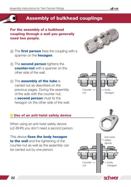
Assembly of bulkhead couplings<br />
For the assembly of a bulkhead<br />
coupling through a wall you generally<br />
need two people.<br />
Assembly Instructions for Twin Ferrule Fittings<br />
Working Pressure for stainless steel<br />
Attention: The system maximum working pressure in bar is<br />
obtained from the lowest of that for the stainless steel tubes,<br />
the type of thread connections and the temperatures used in<br />
each application.<br />
The first person fixes the coupling with a<br />
spanner on the hexagon.<br />
The second person tightens the<br />
counter-nut with a spanner on the<br />
other side of the wall.<br />
The assembly of the tube is<br />
carried out as described on the<br />
previous pages. During the assembly<br />
of the side with the counter nut,<br />
a second person must fix the<br />
hexagon on the other side of the wall.<br />
Counter- <br />
nut<br />
body<br />
hexagon<br />
For couplings with inside or outside threads, compare the maximum<br />
working pressure of the thread with that of the tube used.<br />
The lowest value is the maximum working pressure of the system.<br />
The safety factor for couplings is on the tube connection side 4:1,<br />
for the thread connections 2.5:1 and for the tubes 1.5:1. Due to the<br />
greater wall thickness, threaded connections with outside threads offer<br />
a higher maximum working pressure than those with the equivalent<br />
inside thread.<br />
Couplings with JIC-connection, o-ring sealing or SAE/ MS connections<br />
only offer a lower maximum working pressure. For applications at the<br />
extremes of the recommended working pressures / temperature, it is<br />
recommended to consult our technical department before designing or<br />
assembling an installation.<br />
Use of an anti-twist safety device<br />
Temperatures<br />
When using an anti-twist safety device<br />
(u2-BHR) you don’t need a second person.<br />
This device fixes the body hexagon<br />
to the wall and the tightening of the<br />
counter-nut as well as the assembly can<br />
be carried out by one person.<br />
Counter- <br />
nut<br />
Anti-twist<br />
safety<br />
device<br />
body<br />
hexagon<br />
The maximum working pressures in the charts refer<br />
to a temperature of 25°C to 50°C. For higher<br />
temperatures please multiply the PN with the factor<br />
in this table of temperature related working pressures.<br />
This chart is to be considered only as a guideline and is<br />
subject to change.<br />
We cannot accept guarantee for the use in extreme<br />
temperatures. Maximum working pressure highly<br />
depends on the individual use and fluid. Please<br />
contact our technical department to get an analyses<br />
of the maximum possible working pressure in your<br />
special application.<br />
Temp.<br />
Factor<br />
25°C 1,00<br />
38°C 1,00<br />
100°C 1,00<br />
149°C 1,00<br />
200°C 0,97<br />
250°C 0,90<br />
306°C 0,85<br />
350°C 0,82<br />
400°C 0,80<br />
450°C 0,78<br />
500°C 0,77<br />
600°C 0,62<br />
22<br />
23