railway current voltage transducers

Create successful ePaper yourself
Turn your PDF publications into a flip-book with our unique Google optimized e-Paper software.
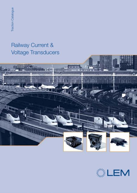
Traction Catalogue<br />
Railway Current &<br />
Voltage Transducers<br />
1
Current and Voltage Transducers<br />
for Railway applications<br />
LEM solutions for traction electrical measurements<br />
Content<br />
Pages<br />
This catalogue summarizes<br />
the most common LEM<br />
product offerings for electrical<br />
<strong>railway</strong> measurements. It is our<br />
business to support you with<br />
both standard and customized<br />
products to optimize your<br />
application.<br />
Please contact LEM in your<br />
region for assistance.<br />
Today, high speed trains,<br />
city transit systems (metro,<br />
trams, and trolleybuses) and<br />
freight trains are the solutions<br />
against pollution and interstate<br />
traffic immobility and provide a<br />
significant energy savings.<br />
Power electronics is essential to<br />
drive and control energy in these<br />
transportation systems.<br />
LEM has been a main player<br />
in traction power electronics<br />
applications and development<br />
for the last 40 years and leverages<br />
this vast experience to supply<br />
solutions for isolated <strong>current</strong><br />
and <strong>voltage</strong> measurements.<br />
LEM <strong>transducers</strong> provide<br />
control and protection signals to<br />
power converters and inverters<br />
that regulate energy to the<br />
electric motors (for propulsion)<br />
and to the auxiliaries (for airconditioning,<br />
heating, lighting,<br />
electrical doors, ventilation,<br />
etc.). This includes the early<br />
monitoring of the <strong>voltage</strong><br />
network (changing by crossing<br />
the European borders) to make<br />
the powers electronics working<br />
accordingly.<br />
Although this is true for<br />
on-board applications, LEM<br />
has also provided the same<br />
control and protection signals<br />
for wayside substations.<br />
The rail industry is under<br />
constant changes and evolution.<br />
As a recent example, the<br />
privatization of the rail networks<br />
raised new requirements for<br />
which LEM provides: the onboard<br />
monitoring of power<br />
consumption (EM4T II Energy<br />
Meter), solutions to trackside<br />
applications, rail maintenance<br />
and the monitoring of points<br />
(switches) machines or signaling<br />
conditions with some new<br />
<strong>transducers</strong> families.<br />
LEM is always available to assist<br />
in adapting to these evolving<br />
technical applications.<br />
Four decades of <strong>railway</strong><br />
experience has contributed to<br />
establishing LEM as a market<br />
leader with worldwide presence<br />
to serve you and provide the<br />
efficient, safe and reliable<br />
operation of the <strong>railway</strong>s.<br />
With more than 2 500 <strong>current</strong><br />
and <strong>voltage</strong> <strong>transducers</strong> in its<br />
portfolio, LEM offers a complete<br />
range of accurate, reliable and<br />
galvanically isolated devices for<br />
the measurement of <strong>current</strong>s<br />
from 0.1 A to 20000 A and<br />
<strong>voltage</strong>s from 10 V to 6 400 V<br />
in various technologies: Open<br />
Loop, Closed Loop, Isolating<br />
digital technology, etc.<br />
LEM <strong>transducers</strong> for <strong>railway</strong><br />
applications are designed<br />
according to the most<br />
demanding international<br />
standards (EN50155, EN50124-<br />
1, NFF 16101, 16102, etc) and<br />
carry CE marking. UL or UR<br />
is also available on selected<br />
models.<br />
We have worldwide ISO 9000<br />
and ISO TS 16949 and IRIS<br />
(Geneva and Beijing LEM<br />
production and design centers)<br />
qualification and offer a 5-year<br />
warranty on all of our products.<br />
LEM constantly innovates<br />
and strives to improve the<br />
performance, cost and sizes<br />
of its products.<br />
LEM is a worldwide company<br />
with offices across the globe<br />
and production facilities in<br />
Europe (included Russia), Asia<br />
and America.<br />
We hope you will find this<br />
catalogue as a useful guide for<br />
the selection of our products.<br />
Visit our website at www.lem.<br />
com and contact our sales<br />
network for further assistance.<br />
Detailed datasheets and<br />
application notes are available.<br />
Sincerely,<br />
Hans-Dieter Huber<br />
Vice President Industry<br />
François Gabella<br />
CEO LEM<br />
LEM - At the heart of power electronics.<br />
Transducer Technologies<br />
On-Board Applications<br />
Substations<br />
Energy Measurement for On-Board<br />
Applications: EM4T II<br />
Specific Railway Applications<br />
Mining Trucks Applications<br />
Trackside Applications<br />
LEM’s Quality & Standards<br />
Solutions for Voltage Measurement<br />
From the Application to the Product<br />
Secondary Connections Options<br />
Design Specification Form<br />
Product Coding<br />
Dimension Drawings<br />
LEM’s Warranty<br />
LEM International Sales<br />
Representatives<br />
About Products:<br />
LTC Series<br />
LF Series<br />
LAC Series<br />
LT 4000 Series<br />
DVL Voltage Series<br />
LV 100-Voltage Series<br />
DV Voltage Series<br />
4 - 5<br />
6 - 15<br />
16 - 19<br />
20 - 23<br />
24 - 25<br />
26 - 27<br />
28 - 31<br />
32 - 33<br />
34 - 35<br />
36 - 37<br />
38<br />
39 - 40<br />
41<br />
42 - 46<br />
47<br />
48<br />
7, 9<br />
11, 14<br />
11<br />
14<br />
15<br />
15<br />
15<br />
2<br />
3
Transducers Technologies<br />
Open Loop Current Transducers (O/L)<br />
Features<br />
• Small package size<br />
• Low power consumption<br />
• Extended measuring range • No insertion losses<br />
• Reduced weight<br />
Operation principle O/L<br />
Closed loop Fluxgate Current <strong>transducers</strong> (ITC Type)<br />
Features<br />
• Excellent linearity<br />
• Better than Class 0.5R<br />
according to EN 50463<br />
• Outstanding long-term stability<br />
• Low residual noise<br />
Operation principle<br />
• Very low sensitivity to high<br />
external DC and AC fields<br />
• High temperature stability<br />
DV & DVL Type Voltage <strong>transducers</strong><br />
Features<br />
• Insulating digital technology<br />
• Measurement of all types of signals:<br />
DC, AC, pulsed and complex<br />
• Compact size, reduced volume<br />
• High galvanic insulation<br />
Operation principle<br />
• Low consumption and losses<br />
• Very high accuracy, Class<br />
0.5R according to EN 50463<br />
• Low temperature drift<br />
Closed Loop Voltage Transducers (C/L)<br />
Features<br />
• Measurement of<br />
high <strong>voltage</strong>s<br />
• Safety isolation<br />
Operation principle C/L<br />
• Good overall accuracy<br />
• Low temperature drift<br />
• Excellent linearity<br />
Transducers Technologies<br />
Primary Current I P<br />
Isolated Output Voltage V OUT<br />
Primary Current I P<br />
Isolated Output Current I S<br />
The magnetic flux created by the primary <strong>current</strong> IP is concentrated<br />
in a magnetic circuit and measured in the air gap using a Hall device.<br />
The output from the Hall device is then signal conditioned to provide<br />
an exact representation of the primary <strong>current</strong> at the output.<br />
Closed Loop Current Transducers (C/L)<br />
Features<br />
• Wide frequency range<br />
• Good overall accuracy<br />
• Fast response time<br />
Operation principle C/L<br />
• Low temperature drift<br />
• Excellent linearity<br />
• No insertion losses<br />
ITC <strong>current</strong> <strong>transducers</strong> are high accuracy <strong>transducers</strong> using fluxgate<br />
technology. This high sensitivity zero-flux detector uses a second<br />
wound core (D’) for noise reduction. A difference between primary and<br />
secondary ampere turns creates an asymmetry in the fluxgate <strong>current</strong>.<br />
This difference is detected by a microcontroller that controls the<br />
secondary <strong>current</strong> that compensates the primary ampere turns (I P x N P ).<br />
This results in a very good accuracy and a very low temperature drift.<br />
The secondary compensating <strong>current</strong> is an exact representation of the<br />
primary <strong>current</strong>.<br />
Closed Loop C Types<br />
Features<br />
• High accuracy<br />
• Very wide frequency range<br />
• Reduced temperature drift<br />
• Excellent linearity<br />
Operation principle<br />
• Measurement of differential<br />
<strong>current</strong>s (CD)<br />
• Safety isolation (CV)<br />
• Reduced loading on<br />
the primary (CV)<br />
The measuring <strong>voltage</strong>, VP, is applied directly to the transducer primary<br />
connections through a resistor network allowing the signal conditioning<br />
circuitry to feed a Sigma-Delta modulator that allows to transmit data<br />
via one single isolated channel.<br />
The signal is then transmitted to the secondary over an insulating<br />
transformer ensuring the insulation between the high <strong>voltage</strong> side<br />
(primary) and the low <strong>voltage</strong> side (secondary).<br />
The signal is reshaped on the secondary side, then decoded and filtered<br />
through a digital filter to feed a micro-controller using a Digital/Analogue<br />
(D/A) converter and a <strong>voltage</strong> to <strong>current</strong> generator.<br />
The recovered output signal is completely insulated against the primary<br />
and is an exact representation of the primary <strong>voltage</strong>.<br />
DI Type Current <strong>transducers</strong> (Shunt isolator)<br />
Features<br />
• Insulating digital technology<br />
• Measurement of all types of signals:<br />
DC, AC, pulsed and complex<br />
• Compact size, reduced volume<br />
• High galvanic insulation<br />
• Low consumption and losses<br />
• Very high accuracy, Class 1R<br />
according to EN 50463<br />
• Low temperature drift<br />
A very small <strong>current</strong> limited by a series resistor is taken from the<br />
<strong>voltage</strong> to be measured and is driven through the primary coil.<br />
The magnetic flux created by the primary <strong>current</strong> IP is balanced by<br />
a complementary flux produced by driving a <strong>current</strong> through the<br />
secondary windings. A hall device and associated electronic circuit are<br />
used to generate the secondary (compensating) <strong>current</strong> that is an exact<br />
representation of the primary <strong>voltage</strong>. The primary resistor (R1) can be<br />
incorporated or not in the transducer.<br />
Operation principle<br />
Primary Current I P Isolated Output Current I S Primary Current I P Isolated Output Current I S<br />
The magnetic flux created by the primary <strong>current</strong> IP is balanced by<br />
a complementary flux produced by driving a <strong>current</strong> through the<br />
secondary windings. A hall device and associated electronic circuit are<br />
used to generate the secondary (compensating) <strong>current</strong> that is an exact<br />
representation of the primary <strong>current</strong>.<br />
This technology uses two toroidal cores and two secondary windings<br />
and operates on the principle of Ampere-turns compensation. For the<br />
<strong>voltage</strong> type a small (few mA) <strong>current</strong> is taken from the <strong>voltage</strong> line to<br />
be measured and is driven through the primary coil and the primary<br />
resistor.<br />
DI <strong>current</strong> <strong>transducers</strong> (Shunt isolator) must be used combined with an<br />
external Shunt.<br />
DI <strong>current</strong> <strong>transducers</strong> are working as DV <strong>voltage</strong> <strong>transducers</strong> except<br />
that the input resistor network used inside the DV is replaced by an<br />
external Shunt providing then the <strong>voltage</strong> input to feed the Sigma-Delta<br />
modulator that allows to transmit data via one single isolated channel.<br />
4<br />
* For further information, refer the brochure “Characteristics - Applications -Calculations” or www.lem.com<br />
5
On-Board Applications<br />
On-Board Applications<br />
The electrical power is supplied to<br />
the trains via the catenaries.<br />
So, depending on the country and<br />
also to the applications (Subway,<br />
trolleybuses, high speed train, heavy<br />
traction…) the locomotives can<br />
operate at different <strong>voltage</strong> levels<br />
and under different systems.<br />
1. Rolling Stock Heavy Traction<br />
Heavy traction means high speed,<br />
or long distances, or heavily loaded<br />
cars (freight trains).<br />
For new lines, not part of an already<br />
existing network, AC <strong>voltage</strong> is often<br />
the choice.<br />
Heavy traction rolling stocks are<br />
made up of (figure 1):<br />
Motor Blower<br />
Air Compressor<br />
Battery<br />
Locomotive Cooling Fans<br />
Auxiliary<br />
Rectifier<br />
3-Phase AC Motors<br />
Auxiliary Inverter<br />
Circuit Breaker<br />
Pantograph<br />
Main Transformer<br />
DC Link<br />
Main Rectifier<br />
Figure 1: Various parts of an AC electric locomotive<br />
- Main transformer,<br />
- Main rectifier,<br />
- DC link to make the connection<br />
to the Main Inverter and Auxiliary<br />
Inverter,<br />
- Main Inverter,<br />
- Auxiliary Inverter.<br />
Main Transformer<br />
Power from the catenaries route<br />
through the main circuit breaker<br />
before reaching the main transformer.<br />
This is the first place where a <strong>current</strong><br />
transducer can be advantageous:<br />
The control of the input <strong>current</strong><br />
(N°1a in the figure 2). The LT 2005<br />
& 4000 models bring the necessary<br />
advantages for that job: a large<br />
aperture for cable pass-through of<br />
the primary conductor as well as<br />
high isolation <strong>voltage</strong>.<br />
Although it is a complex undertaking<br />
to design a train capable of operating<br />
in different countries with various<br />
electrical <strong>railway</strong> catenary <strong>voltage</strong>s,<br />
it has been possible due to advances<br />
in modern power electronics.<br />
Eurostar, for example, is able to run<br />
over four different <strong>voltage</strong>s, 25 kV/<br />
AC/50 Hz, 3 kV DC, 1.5 kV DC and<br />
750 V DC.<br />
The LV 100-Voltage series used at<br />
this level allows the detection of the<br />
<strong>voltage</strong> network, informing about<br />
the country where is running the<br />
locomotive (N°:1c in the figure 2).<br />
To ensure the protection of the whole<br />
system, the earth leakage <strong>current</strong> to<br />
the wheels is also monitored thanks<br />
to special <strong>current</strong> <strong>transducers</strong><br />
called CD series dedicated for that<br />
function (N°:1b in the figure 2).<br />
They are responsible for measuring<br />
Axle<br />
Brush<br />
3-Phase AC Motors<br />
To other 3-phase AC motors<br />
Circuit<br />
Breaker<br />
1c<br />
1a<br />
Transformer<br />
1b<br />
U<br />
V<br />
Main Inverter<br />
differential <strong>current</strong> between 2 or 3<br />
conductors and detecting possible<br />
leakage between these conductors.<br />
It is also possible to accomplish this<br />
measurement by using 2 typical<br />
traction <strong>current</strong> <strong>transducers</strong> like the<br />
HAR 1000 or LT 2005 families.<br />
4 - Quadrant Controller DC - Link<br />
2<br />
2 5<br />
Uz<br />
CA<br />
3c<br />
3a<br />
3b<br />
Inverter<br />
Figure 2: Where is the <strong>current</strong> and <strong>voltage</strong> measurement on the traction drive system ?<br />
No contact and galvanically<br />
isolated differential measurement<br />
with a large aperture for multiple<br />
primary conductors result in safetyfriendly<br />
<strong>transducers</strong> and accurate<br />
measurement.<br />
Multi winding transformers convert<br />
the catenary <strong>voltage</strong> to a <strong>voltage</strong><br />
compatible with the power<br />
converters.<br />
To get the best efficiency of the<br />
energy provided by the network,<br />
accurate and reliable measurement<br />
is required. LEM proposes the<br />
adapted measurement tool<br />
“EM4T II”, adapted to various<br />
European networks (please see<br />
section dedicated to EM4T II).<br />
One of the secondary windings of<br />
this transformer is used to build a<br />
four-quadrant controller.<br />
Main Rectifier<br />
This is generally made up by a four<br />
quadrant controller to be connected<br />
to the DC link.<br />
A four quadrant controller can<br />
regulate the flow of energy from<br />
the AC line to the DC link and from<br />
the DC link back to the AC line. It<br />
allows to have the power, taken<br />
from the catenaries, nearly close to<br />
the maximum theoretical value for a<br />
given <strong>current</strong> and this over a large<br />
range of speed and traction effort.<br />
In simple terms, this is an active<br />
rectifier.<br />
This step is necessary for the 15 kV/<br />
AC/16Hz 2/3 and 25 kV/AC/50Hz<br />
networks, in order to decrease<br />
the <strong>voltage</strong> level, and, also, to<br />
convert the <strong>voltage</strong> to a DC value,<br />
which has been defined as the best<br />
compromise for the <strong>voltage</strong>/<strong>current</strong><br />
supplied to today’s semiconductors.<br />
2000 V is a typical value at this stage<br />
of the <strong>voltage</strong> transformation.<br />
The control of the input <strong>voltage</strong><br />
(main transformer output) is ensured<br />
by LV 100-Voltage or DV Voltage<br />
<strong>transducers</strong> (N°:5 in the figure 2).<br />
6<br />
6<br />
4<br />
4<br />
4<br />
M<br />
SMA Technologie AG<br />
Copyright ALSTOM<br />
500 A<br />
LTC FAMILY<br />
1000 A<br />
350 A<br />
500 A<br />
Mounting flexibility horizontal or vertical<br />
Multiple options for a full modularity<br />
Various secondary connections<br />
Various busbars<br />
Various feet<br />
On-Board Applications<br />
6<br />
7
On-Board Applications<br />
One <strong>current</strong> transducer may be used<br />
for the input <strong>current</strong> measurement<br />
to control and protect the four<br />
quadrant controller (N°:2 in the<br />
figure 2) such as models derived<br />
from LTC 1000 or LT 1005 Series.<br />
DC Link<br />
This is the link between the main<br />
rectifier output and the propulsion<br />
inverter input and the auxiliary<br />
inverter.<br />
Its goal is to smooth the DC signal,<br />
limit the <strong>voltage</strong> (overloads), and/or<br />
filter the perturbations coming from<br />
the source (catenary/transformer) to<br />
the inverter or vice-versa.<br />
A <strong>voltage</strong> transducer derived from<br />
the LV 100-Voltage family can be<br />
used for these functions (there are<br />
many models available for 2000<br />
V measurement which is a typical<br />
value at this level) (N°:3c in the figure<br />
2). DVL Series <strong>transducers</strong> can also<br />
be a solution if frequency to follow is<br />
higher. The polarity on the DC link is<br />
also a controlled parameter.<br />
Current overloads and polarity are<br />
also monitored by some <strong>current</strong><br />
<strong>transducers</strong> to avoid power<br />
semiconductor damage (N°:3a in<br />
the figure 2): LT 1005, 2005, LTC<br />
1000 and LF 2005 families.<br />
In the case of a direct DC <strong>voltage</strong><br />
supplied by the catenaries (no<br />
transformer, no rectifier) (for<br />
subways, or trolleybuses for<br />
example, <strong>voltage</strong> line between<br />
600 to 900 V DC), the DC link<br />
could then be made up of a simple<br />
inductance and some capacitors<br />
(LV 100-Voltage <strong>transducers</strong> range<br />
covers also these values as well as<br />
the LV 25-Voltage models) (N°:3c in<br />
the figure 2).<br />
As for measurement of differential<br />
leakage <strong>current</strong>s at this level,<br />
the CD series <strong>transducers</strong> would<br />
satisfy the requirement (N°:3b in<br />
the figure 2).<br />
Main Inverter or Drive Propulsion<br />
Inverter<br />
In the past, some other propulsion<br />
principles were running using series<br />
DC <strong>current</strong> motors. Initially, the<br />
adjustment of the motor speed and<br />
torque was controlled by switched<br />
series resistors (figure 3).<br />
U DC<br />
Figure 3 : DC motor control per resistors adjustment<br />
Years later, choppers appeared<br />
with the use of the semiconductors<br />
(thyristors, then GTO thyristors<br />
or IGBT transistors). This last<br />
propulsion system is still often used<br />
today for <strong>railway</strong> traction (figure 4).<br />
U DC U DC<br />
M<br />
3<br />
Figure 4 : DC motor control per<br />
chopper<br />
Today, however, the most popular<br />
way to propel the train is the<br />
asynchronous motor where the<br />
power is supplied by inverters.<br />
Indeed, asynchronous motors bring<br />
advantages such as compactness,<br />
robustness, less expensive for<br />
maintenance, and increased<br />
productivity.<br />
(Synchronous motors are also<br />
often used for TGV propulsion for<br />
example).<br />
The inverter is transforming the DC<br />
<strong>voltage</strong> supplied by the DC link into<br />
an AC <strong>voltage</strong> for a three phase<br />
system.<br />
The frequency and amplitude of<br />
the root (base) signal can then be<br />
adjusted.<br />
The most used inverter today is<br />
the PWM (Pulse Width Modulation)<br />
inverter. This is made up of six<br />
electronic switches (initially GTOs<br />
followed by IGBTs) as represented<br />
in figure 5.<br />
Figure 5 : AC motor control per<br />
PWM inverter<br />
The switching frequency is normally<br />
as high as possible.<br />
The motor <strong>voltage</strong> follows a sinusoidal<br />
profile and the fundamental<br />
frequency of the <strong>current</strong> and the<br />
<strong>voltage</strong> supplied are functions of the<br />
required motor speed. Depending<br />
on the required torque, <strong>voltage</strong> and<br />
<strong>current</strong> amplitudes fluctuate with the<br />
frequency.<br />
To control these motor <strong>current</strong><br />
LTC series : Modular Current <strong>transducers</strong><br />
Measures DC, AC, pulsed … <strong>current</strong>s with galvanic isolation<br />
Mountable in 4 positions : 0º, 90º, 180º, 270º<br />
Different accessories : mounting feet, clamps, bus bars<br />
more details on page 4 of each -S data sheet<br />
Technical data in short form. For more details please see data sheet<br />
Without accessories LTC 350-S LTC 500-S LTC 600-S LTC 1000-S<br />
With clamps 1) 1) 1) 1)<br />
With feets LTC 350-SF LTC 500-SF LTC 600-SF LTC 1000-SF<br />
With clamps and feets 1) 1) LTC 600-SFC LTC 1000-SFC<br />
With bus bar LTC 350-T LTC 500-T LTC 600-T LTC 1000-T<br />
With bus bar and feets LTC 350-TF LTC 500-TF LTC 600-TF LTC 1000-TF<br />
Other types: contact sales < < < <<br />
Special features : contact sales < < < <<br />
Different bus bars are available yes yes yes yes<br />
Parameter Description Condition unit<br />
350…1000 A RMS<br />
Closed loop<br />
Hall cell<br />
LTC 600 & 1000 Transducer /<br />
Mechanical adaptation accessories<br />
(same possibilities for LTC 350<br />
and 500 models)<br />
I PN<br />
Primary nominal <strong>current</strong> A RMS<br />
350 500 500 1000<br />
I P Measuring range, primary @ ±24V A peak ±1200 ² ±1200 ² ±1500 ² ±2400 ²<br />
Î P Max. not measurable overload kA / ms 10 / 10 10 / 10 10 / 10 10 / 10<br />
R Mmax<br />
Max. Measuring resistance @ ±24V Ω 60 110 150 50<br />
R Mmax Max. Measuring resistance @ ±15V Ω 30 50 70 15<br />
R Mmin Min. Measuring resistance @ ±24V Ω 10 0 0 0<br />
R Mmin Min. Measuring resistance @ ±15V Ω 0 0 0 0<br />
K N Conversion ratio 1 : 2000 1 : 4000 1 : 5000 1 : 5000<br />
I SN Secondary nominal <strong>current</strong> mA 175 125 100 200<br />
V C Supply <strong>voltage</strong> ±5% V ±15…24 ±15…24 ±15…24 ±15…24<br />
I C Current consumption @ ±24V mA < 35 + I S < 35 + I S < 30 + I S < 30 + I S<br />
Vd Dielectric strength 50Hz 1min. kV RMS 12 12 13.4 13.4<br />
X G Overall accuracy @ I PN , T A = 25ºC % < ± 0.5 < ± 0.6 < ± 0.7 < ± 0.4<br />
ε L<br />
@ I PN , T A = -40…+85ºC % < ± 1.6 < ± 1<br />
Linearity error % < 0.1 < 0.1 < 0.1 < 0.1<br />
I O Offset <strong>current</strong> @ I P =0, T A =25ºC mA ≤ ±0.5 ≤ ±0.5 ≤ ±0.5 ≤ ±0.5<br />
I OT Thermal drift of I O -40…+85ºC mA ≤ ±0.8 ≤ ±0.8 ≤ ±1 ≤ ±1<br />
t r Response time @90% of I PN μs < 1 < 1 < 1 < 1<br />
di/dt accurately followed A/μs > 100 > 100 > 100 > 100<br />
BW Frequency bandwidth -1dB kHz DC…100 DC…100 DC…100 DC…100<br />
T A Ambient operating temperature ºC -40…+85 -40…+85 -40…+85 -40…+85<br />
T S<br />
Ambient storage temperature ºC -45…+90 -45…+90 -45…+90 -45…+90<br />
R S Secondary coil resistance @ T A = +85ºC Ω 15 47 44 44<br />
m Mass -S model g 400 400 750 750<br />
Standards EN50155 yes yes yes yes<br />
Secondary connection M5, Faston M5, Faston M5, Faston M5, Faston<br />
Shield between primary and secondary yes yes yes yes<br />
On-Board Applications<br />
8<br />
1) order separately<br />
2) more details: see data sheet<br />
9
On-Board Applications<br />
parameters, LTC <strong>current</strong> <strong>transducers</strong><br />
located on each phase of the<br />
asynchronous motor, fulfill all the<br />
<strong>railway</strong> requirements for 350 to 1000<br />
A nominal <strong>current</strong> measurements<br />
(N°:4 in the figure 2): The LTC<br />
is modular, compact, designed<br />
for traction, many possibilities of<br />
secondary connections, and fully<br />
approved for traction.<br />
The LT 505, 1005, and 2005 series<br />
are also recognized for this function,<br />
and have been used for several<br />
years in these applications.<br />
The higher the chopping frequency,<br />
the more sinusoidal is the <strong>current</strong><br />
waveform.<br />
The choice of a Closed Loop Hall<br />
effect based transducer is justified:<br />
- to get a fast response time (for<br />
protection purpose),<br />
- to “see” and support high<br />
frequency signals of the <strong>current</strong><br />
(ripple on the fundamental) from<br />
the high switching frequency of<br />
the inverter,<br />
- and to achieve accurate control<br />
of the speed.<br />
Several propulsion motors can be<br />
connected in parallel at the inverter<br />
output.<br />
Depending on the equipment manufacturer,<br />
some techniques are possible<br />
to improve the <strong>voltage</strong> waveform<br />
applied to the motor or to decrease<br />
the motor harmonic <strong>current</strong>s.<br />
The PWM inverter output phase<br />
<strong>voltage</strong>s can also be controlled with<br />
help from two <strong>voltage</strong> <strong>transducers</strong><br />
derived from the LV 100-Voltage,<br />
DV Voltage or DVL Voltage or CV-<br />
Voltage families for speed control<br />
(N°:6 in the figure 2).<br />
Auxiliary Inverter<br />
Auxiliary inverters are the systems<br />
supplying other on-board loads.<br />
Although, not as popular, they<br />
are essential to the auxiliary loads<br />
needed for the propulsion and for<br />
the passengers’ comfort.<br />
Depending on the catenary <strong>voltage</strong>s<br />
on the applied loads at the<br />
output, on the constraints dictated<br />
by the car itself (where it will<br />
be mounted : On the roof, into<br />
the floor…) or by the application<br />
(environment)…, the electronic<br />
schematics for the auxiliary inverters<br />
are various, and, they use in all the<br />
cases all the last innovations of the<br />
power electronics.<br />
They have to bring the following<br />
advantages to the application:<br />
- Compact,<br />
- Light weight,<br />
- High yield, low cost and low<br />
maintenance,<br />
- High performance.<br />
For DC power, auxiliary inverters can<br />
be fed directly from the catenaries<br />
and for AC power, they can be<br />
connected to the main transformer<br />
through a secondary winding, but<br />
can also be connected to the main<br />
or intermediate rectifier ouput.<br />
By converting the <strong>voltage</strong> and<br />
<strong>current</strong> under various waveforms<br />
(DC, AC, different frequencies,<br />
stable or variable frequency), they<br />
have the responsibility to supply<br />
systems such as:<br />
- Batteries: The DC <strong>voltage</strong><br />
provides charge to the battery<br />
at different values depending<br />
on the country and the traction<br />
vehicle (24, 48, 72 or 110 V being<br />
the most widely used).<br />
The batteries are used to provide<br />
start-up <strong>current</strong>, for emergency<br />
lighting when the line supply<br />
fails, or to supply power to other<br />
auxiliary circuits.<br />
Charging and discharging of<br />
the batteries are monitored by<br />
<strong>voltage</strong> <strong>transducers</strong>. Depending<br />
on the accuracy needed for<br />
this type of monitoring, various<br />
models are available.<br />
The CV 3 models are designed<br />
for high accurate measurement<br />
throughout their measuring ranges<br />
followed by the DV Voltage,<br />
DVL Voltage and LV 100-Voltage<br />
models.<br />
- Resistances and windings,<br />
- Motors: DC or even AC motors<br />
operating under three phases<br />
380-400 V/50-60 Hz for car<br />
ventilation, traction motors fans<br />
and traction compartment fans,<br />
blowers, pumps, compressors,<br />
etc.The start-up and shutdown<br />
of these motors are automatically<br />
controlled by other on-board<br />
systems but still require <strong>current</strong><br />
overload support from the<br />
auxiliary inverter.<br />
- Various electronics: AC singlephase<br />
power supplies control<br />
power, power plugs, lighting, etc.<br />
These <strong>voltage</strong>s have to be filtered<br />
and stabilized since the catenary<br />
<strong>voltage</strong>s can fluctuate. The<br />
auxiliary inverter must sustain<br />
any high transient over<strong>voltage</strong>s<br />
that may occur.<br />
- Transformers…<br />
Additionally, these systems support<br />
the operation of HVAC heating<br />
and doors openers while having<br />
to operate from several possible<br />
<strong>voltage</strong> networks for European cars.<br />
The passenger’s comfort is<br />
represented more and more in these<br />
systems and consequently increases<br />
the overall energy requirements. The<br />
auxiliary inverters have to rationalize<br />
the best energy consumption by<br />
using the latest power electronics<br />
technology and take advantage of<br />
any possible energy savings.<br />
For the previous mentioned reasons<br />
(protection and control), monitoring<br />
the DC or AC <strong>current</strong>s and <strong>voltage</strong>s<br />
at the input and output of the<br />
inverter is needed. This is also<br />
essential for successful loop control.<br />
Again, depending on the regulation<br />
accuracy required, the choices for<br />
<strong>voltage</strong> and <strong>current</strong> <strong>transducers</strong><br />
are various. Furthermore, auxiliary<br />
inverters are subject to cost<br />
pressures and often the least<br />
expensive measuring solutions<br />
are the final preferences. In this<br />
context, the best compromise of<br />
the price/performance ratio for<br />
the <strong>voltage</strong> measurement is the LV<br />
25-Voltage family (200 V to 1200<br />
V) and for <strong>current</strong> measurements,<br />
models derived from the LTC and<br />
LAC families are typically the best<br />
solutions. All use the Closed Loop<br />
Hall effect technology providing<br />
high bandwidth, overall accuracy<br />
at + 25°C between 0.4 and 0.8<br />
% of nominal <strong>current</strong> (or <strong>voltage</strong>)<br />
LF series : Compact Current <strong>transducers</strong><br />
Measures DC, AC, pulsed … <strong>current</strong>s with galvanic isolation<br />
Choice between different electrical parameters<br />
Choice between different output connectors, studs, cables<br />
LF FAMILY<br />
Very compact<br />
packages<br />
200 A<br />
300 A<br />
1000 A<br />
500 A<br />
2000 A<br />
Technical data in short form. For more details please see data sheet<br />
100…2000 A RMS<br />
Closed loop<br />
Hall cell<br />
LAC 300-S<br />
Mounting versatility<br />
Several horizontal or<br />
vertical mountings<br />
LF 205-S/SP5 LF 205-S/SP1 LF 305-S/SP10 LAC 300-S<br />
Other types: contact sales < < < <<br />
Special features : contact sales < < < <<br />
Different bus bars are available no no no no<br />
Parameter Description Condition unit<br />
I PN<br />
I P<br />
Î P<br />
R Mmax<br />
R Mmax<br />
R Mmin<br />
R Mmin<br />
K N<br />
I SN<br />
V C<br />
I C<br />
Vd<br />
Primary nominal <strong>current</strong> A RMS 100 200 300 400<br />
Measuring range, primary @ ±12…15V A peak ±200 ¹ ±420 ¹ ±500 ¹ ±650 ¹<br />
Max. not measurable overload<br />
kA / ms<br />
Max. Measuring resistance @ ±15V Ω 123 100 58 15<br />
Max. Measuring resistance @ ±12V Ω 95 71 39<br />
Min. Measuring resistance @ ±15V Ω 16 0 0 0<br />
Min. Measuring resistance @ ±12V Ω 0 0 0<br />
Conversion ratio 1 : 1000 1 : 2000 1 : 2000 1 : 4000<br />
Secondary nominal <strong>current</strong> mA 100 100 150 100<br />
Supply <strong>voltage</strong> ±5% V ±12…15 ±12…15 ±12…20 ±15<br />
Current consumption @ ±15V mA 17 + I S 17 + I S<br />
16 + I S<br />
25 + I S<br />
Dielectric strength 50Hz 1min. kV RMS<br />
3.5 3.5 3 5.5<br />
X G<br />
Overall accuracy @ I PN<br />
, T A<br />
= 25ºC % < ± 0.6 < ± 0.5 < ± 0.5 < ± 1<br />
ε L<br />
@ I PN<br />
, T A<br />
= -40…+85ºC %<br />
Linearity error % < 0.1 < 0.1 < 0.1 < 0.1<br />
I O Offset <strong>current</strong> @ I P =0, T A =25ºC mA ≤ ±0.2 ≤ ±0.2 ≤ ±0.2 ≤ ±0.15<br />
I OM Residual <strong>current</strong> @I P after overload 3 x I PN mA ≤ ±0.2 ≤ ±0.1 ≤ ±0.2 ≤ ±0.15<br />
I OT<br />
Thermal drift of I o<br />
-40…+85ºC mA typ. ±0.25 typ. ±0.12 typ. ±0.2 typ. ±0.2<br />
tra Reaction time @10% of I PN ns < 500 < 500 < 500<br />
tr Response time @90% of I PN<br />
μs < 1 < 1 < 1 < 1<br />
di/dt accurately followed A/μs > 100 > 100 > 100 > 50<br />
BW Frequency bandwidth -1dB kHz<br />
-3dB kHz DC…100 DC…100 DC…100 DC…50<br />
T A Ambient operating temperature ºC -40…+85 -40…+85 -40…+85 -40…+85<br />
T S Ambient storage temperature ºC -40…+90 -40…+90 -40…+85 -45…+90<br />
R S<br />
Secondary coil resistance @ T A<br />
= +70ºC Ω 10 33 30<br />
" @ T A = +85ºC Ω 11 35 32 67<br />
m Mass g 78 78 95 137<br />
Standards EN50155 yes yes ² yes yes<br />
Secondary connection Molex Minif.5566 Molex Minif.5566 Molex Minif.5566 Molex 70543-0003<br />
Shield between primary and secondary no no no no<br />
On-Board Applications<br />
10<br />
1) more details: see data sheet<br />
2) except § 10.2.6.2<br />
11
On-Board Applications<br />
and fast response time for <strong>current</strong><br />
<strong>transducers</strong> (less than 1 µs @ 90<br />
% of Ipn).<br />
If mounting constraints or overall<br />
dimensions restrictions are relevant<br />
then other models can be used for<br />
this function, such as the LA 205 /<br />
305 series or LT and LF 505 / 1005<br />
/ 2005-S families for example.<br />
However, if the price is the main<br />
issue and if overall accuracy of<br />
1 % of Ipn at +25°C, a slightly<br />
longer response time (between 3<br />
and 10µs @ 90 % of Ipn) and a<br />
shorter bandwidth (10 to 50 kHz) are<br />
acceptable in the application then,<br />
the solution might be an Open Loop<br />
Hall effect based <strong>current</strong> transducer:<br />
the HTA, HAR or HTC series.<br />
2. Rolling Stock Light Rail<br />
Cars (Trolleybus/Tramways)<br />
In principle, there is no major<br />
difference between the diagrams of<br />
heavy traction and light rail traction<br />
systems.<br />
Both are mainly propelled by<br />
asynchronous motors. As for<br />
the heavy traction, the chopper<br />
technology is still often used to<br />
supply a series DC <strong>current</strong> traction<br />
motor.<br />
They operate mainly from DC<br />
<strong>voltage</strong>s supplied by the catenaries<br />
with typical values such as: 600 V,<br />
750 V, 900 V, 1200 V or 1500 V at<br />
the maximum.<br />
The main transformer and rectifier<br />
are then not needed.<br />
Auxiliary inverters are also used, as<br />
for the heavy traction, to generate<br />
either three phase AC 380 V <strong>voltage</strong><br />
or DC <strong>voltage</strong> (24, 48 V or more)<br />
for battery chargers. Both <strong>voltage</strong>s<br />
(DC and AC three phase output<br />
<strong>voltage</strong>s) can be isolated from the<br />
auxiliary inverter with an intermediate<br />
transformer.<br />
Trolleybuses as well as tramways are<br />
becoming more and more important<br />
in cities to reduce the local air pollution.<br />
Trolleybuses are however<br />
more abundant than tramways, as<br />
they require less significant infrastructure<br />
and also, as they are more<br />
convenient for steep grades (where<br />
tramways are not possible).<br />
Often combined with a diesel engine<br />
(bi-mode), the rail network can be<br />
extended outside cities by using the<br />
diesel mode. Also, the trolleybuses<br />
and tramways, with their batteries<br />
charged via the auxiliary inverter or<br />
through wheel inertia or “Sup Cap,”<br />
ensure their electrical propulsion in<br />
places where electrical networks<br />
are not possible for architectural<br />
reasons for example: High flexibility.<br />
3. Rolling Stock Underground<br />
(Subways)<br />
At one time, subways propulsion<br />
systems were based on resistor<br />
control to control a series DC <strong>current</strong><br />
traction motor then, chopper control<br />
was progressively introduced in the<br />
70’s to reduce the power losses<br />
and finally, combined with the<br />
regenerative braking to reduce<br />
overheating in tunnels and to save<br />
energy. Most of the recent deliveries<br />
are now based on inverters<br />
controlling asynchronous motors.<br />
They operate mainly from DC<br />
<strong>voltage</strong>s supplied by the rails (third<br />
rail or 2 lateral rails) or by a catenary<br />
(for suburban lines) with typical<br />
values: 600 V, 750 V up to 1500 V<br />
at the maximum.<br />
Subway systems also use auxiliary<br />
inverters for auxiliary functions such<br />
as ventilation, air-conditioning,<br />
doors openers, etc., similar to heavy<br />
traction, trolleybuses and tramways.<br />
4. Rolling Stock Heavy Traction<br />
Diesel-Electric :<br />
In the past, locomotives operating<br />
where no electrical networks exist<br />
had only a couple of options:<br />
The diesel engine drives:<br />
1. DC <strong>current</strong> generator,<br />
2. or, a three phase alternating<strong>current</strong><br />
generator.<br />
Both scenarios need to supply power<br />
to DC motors for the propulsion.<br />
The three phase alternating-<strong>current</strong><br />
generator must use a rectifier at the<br />
output to convert back to DC.<br />
Current control from the generators<br />
is accomplished by a rheostat or a<br />
group of contactors.<br />
Traction power is controlled by<br />
adjusting the rotational speed<br />
setting of the diesel engine.<br />
DC <strong>voltage</strong>s generated can be from<br />
400 to 1500 V with <strong>current</strong>s from<br />
500 A to 2500 A DC.<br />
But as for all the other rolling stock,<br />
the trend is asynchronous motors.<br />
Today, we see that the share is 80<br />
% with AC and 20 % DC.<br />
This trend can also be justified by<br />
the requirement to reduce the fuel<br />
consumption.<br />
Indeed, asynchronous motors provide<br />
better yield than DC in the same<br />
application.<br />
The whole electrical system is<br />
similar to the one used for the<br />
heavy traction except that the initial<br />
AC power is generated by the AC<br />
generator (alternator).<br />
The needs in <strong>current</strong> and <strong>voltage</strong><br />
measurements are the same as<br />
previously detailed in the other rolling<br />
stocks.<br />
Auxiliary Inverter<br />
Copyright Bombardier<br />
Copyright ALSTOM<br />
2000 A<br />
Copyright ALSTOM<br />
Large <strong>current</strong> range capability up to 4000 A<br />
Large choice of secondary<br />
connections<br />
Busbar or aperture<br />
LA 205 / 305 FAMILY<br />
300 A<br />
200 A<br />
1000 A<br />
LT FAMILY<br />
4000 A<br />
500 A<br />
On-Board Applications<br />
12<br />
13
On-Board Applications<br />
LF series : Compact Current <strong>transducers</strong><br />
Measures DC, AC, pulsed … <strong>current</strong>s with galvanic isolation<br />
Choice between different electrical parameters<br />
Choice between different output connectors, studs, cables<br />
LF FAMILY<br />
Very compact<br />
packages<br />
200 A<br />
300 A<br />
1000 A<br />
500 A<br />
2000 A<br />
100…2000 A RMS<br />
Closed loop<br />
Hall cell<br />
DV and DVL series : Voltage <strong>transducers</strong><br />
Measures DC, AC, pulsed … Voltages with galvanic isolation<br />
Choice between different electrical parameters<br />
Choice between different output connectors, studs, cables<br />
50 V…4200 V RMS<br />
Isolation Amplifier<br />
Insulating Digital<br />
Technologies<br />
On-Board Applications<br />
Technical data in short form. For more details please see data sheet<br />
LF 505-S/SP23 LF 1005-S/SP14 LF 2005-S/SP1 LT 4000-S/SP34<br />
Other types: contact sales < < < <<br />
Special features : contact sales < < < <<br />
Different bus bars are available no no yes yes<br />
Parameter Description Condition unit<br />
I PN<br />
Primary nominal <strong>current</strong> A RMS 500 1000 2000 4000<br />
I P<br />
Measuring range, primary @ ±24V A peak ±1000 ¹ ±1500 ¹ ±3500 ¹ ±6000 ¹<br />
Î P<br />
Max. not measurable overload kA / ms 20<br />
R Mmax<br />
Max. Measuring resistance @ ±24V Ω 114 50 6 10<br />
R Mmax<br />
Max. Measuring resistance @ ±15V Ω 8<br />
R Mmin<br />
Min. Measuring resistance @ ±24V Ω 0 3 3 2<br />
R Mmin<br />
Min. Measuring resistance @ ±15V Ω 0<br />
K N<br />
Conversion ratio 1 : 5000 1 : 5000 1 : 5000 1 : 5000<br />
I SN<br />
Secondary nominal <strong>current</strong> mA 100 200 400 800<br />
V C<br />
Supply <strong>voltage</strong> ±5% V ±24 ±24 ±15…24 ±24<br />
I C<br />
Current consumption @ ±24V mA 34 + I S<br />
28 + I S<br />
33 + I S<br />
35 + I S<br />
Vd Dielectric strength 50Hz 1min. kV RMS 6 6 10 12<br />
X G<br />
ε L<br />
I O<br />
I OM<br />
I OT<br />
tra<br />
tr<br />
di/dt<br />
BW<br />
T A<br />
T S<br />
R S<br />
m<br />
Overall accuracy @ I PN , T A = 25ºC % < ± 0.6 < ± 0.5 < ± 0.3 < ± 0.5<br />
@ I PN , T A = -40…+85ºC %<br />
Linearity error % < 0.1 < 0.1 < 0.1 < 0.1<br />
Offset <strong>current</strong> @ I P =0, T A =25ºC mA ≤ ±0.4 ≤ ±0.4 ≤ ±0.5 ≤ ±0.8<br />
Residual <strong>current</strong> @I P after overload 3 x I PN mA ≤ ±0.2<br />
Thermal drift of I O mA typ. ±0.3 typ. ±0.3 typ. ±0.2 typ. ±0.6<br />
Reaction time @10% of I PN ns<br />
Response time @90% of I PN μs < 1 < 1 < 1 < 1<br />
accurately followed A/μs > 100 > 100 > 100 > 50<br />
Frequency bandwidth -1dB kHz DC…100 DC…150 DC…150 DC…100<br />
-3dB<br />
kHz<br />
Ambient operating temperature ºC -40…+85 -40…+85 -40…+85 -25…+70<br />
Ambient storage temperature ºC -45…+90 -45…+100 -50…+85 -40…+85<br />
Secondary coil resistance @ T A = +70ºC Ω 15<br />
@ T A = +85ºC Ω 96 55 26<br />
Mass g 230 500 1500 6000<br />
Standards EN50155 yes yes yes yes<br />
Secondary connection screen cable 2m M4 studs Lemo EEJ...CYC M5 studs<br />
Shield between primary and secondary yes yes yes no<br />
1) more details: see data sheet<br />
Technical data in short form. For more details please see data sheet<br />
DVL 1000 LV 100-2000/SP15 DV 1200/SP2 DV 4200/SP4<br />
Other types: contact sales < < < <<br />
Special features : contact sales < < < <<br />
Parameter Description Condition unit<br />
V PN Primary nominal <strong>voltage</strong> V RMS 1000 2000 1200 4200<br />
V PM Measuring range, primary @ ±24V V ±1500 ¹ ±3000 ¹ ±1800 ¹ ±6000 ¹<br />
V P Max. not measurable overload<br />
1s/h<br />
R Mmax Max. Measuring resistance @ ±24V Ω 120<br />
330 28 140<br />
R Mmax Max. Measuring resistance @ ±15V Ω 120 180 7<br />
R Mmin Min. Measuring resistance @ ±24V Ω 0 60 0 60<br />
R Mmin Min. Measuring resistance @ ±15V Ω 0 0 0 0<br />
I SN Secondary nominal <strong>current</strong> mA 50 50 50 50<br />
V C Supply <strong>voltage</strong> ±5% V ±15…24 ±15…24 ±15…24 ±15…24<br />
I C Current consumption @ ±24V mA 20 + I S 25 + I S 20 + I S 20 + I S<br />
V e Partial discharge extinction <strong>voltage</strong> RMS@ 10pC kV 2.7 5 5<br />
Vd Dielectric strength 50Hz 1min. kV RMS<br />
8.5 9 18.5 18.5<br />
X G<br />
ε L<br />
I O<br />
I OT<br />
tr<br />
BW<br />
Overall accuracy @ V PN , T A = 25ºC % < ± 0.5 < ± 1 < ± 0.3 < ± 0.3<br />
@ V PN<br />
, T A<br />
= -40…+85ºC % < ± 1 < ± 1.7 < ± 1,2 < ± 1<br />
Linearity error % < 0.5 < 0.1 < 0.1 < 0.1<br />
Offset <strong>current</strong> @ V P<br />
=0, T A<br />
=25ºC mA ≤ ±0.05 ≤ ±0.3 ≤ ±0.5 ≤ ±0.5<br />
Thermal drift of Io -40…+75ºC 2) , +85ºC 3) mA max ±0.15 typ. ±0.4 max ±0.3 max ±0.1<br />
Response time @90% of V PN<br />
μs < 50 < 70
Substations<br />
Substations<br />
Most of the trains are powered<br />
electrically. The necessary power<br />
to energize the electrical motors for<br />
locomotive propulsion is generated<br />
at the <strong>railway</strong> substations.<br />
Power substations convert the<br />
high <strong>voltage</strong> provided by the utility<br />
company’s distribution lines to the<br />
low <strong>voltage</strong> (AC or DC) and supply it<br />
with direct <strong>current</strong> needed to operate<br />
<strong>railway</strong> vehicles.<br />
Once generated, the <strong>voltage</strong><br />
and <strong>current</strong> are distributed to the<br />
locomotives or rolling stocks via<br />
the catenaries or rails (for urban<br />
underground <strong>railway</strong> for example).<br />
The <strong>voltage</strong>s generated by the<br />
substations are various, due to the<br />
different possible <strong>voltage</strong> networks<br />
existing, according to the country<br />
where the rolling stocks are running.<br />
All the following <strong>voltage</strong> networks<br />
exist in Europe:<br />
- 1.5 kV DC : in south of France,<br />
Netherlands…<br />
- 3 kV DC : in Spain, Italia, Latvia,<br />
Slovenia, Estonia, Poland,<br />
Belgium,Croatia, Moldavia…<br />
representing about 30 % of the<br />
worldwide <strong>railway</strong> electrical lines,<br />
- 15 kV / AC / 16.7 Hz: in<br />
Germany, Switzerland, Austria,<br />
Norway, Sweden...<br />
- 25 kV/AC/50 Hz : Portugal,<br />
North of France, North of UK,<br />
Finland, Belarus, Yugoslavia,<br />
Bosnia & Herzegovina,<br />
Macedonia, Greece, Romania,<br />
Bulgaria, Hungary, Lithuania,<br />
Denmark…<br />
- 3 kV DC and 25 kV/AC/50 Hz :<br />
Czech Republic, Slovakia,<br />
Ukraine, Russia…<br />
- 750 V DC : UK…<br />
Today, the trend is to have more<br />
and more heavy rolling stocks<br />
powered with <strong>voltage</strong> lines under<br />
AC <strong>voltage</strong>.<br />
For the subways, trolleybuses, or<br />
tramways the <strong>voltage</strong> line is typically<br />
between 600 to 900 V DC (600,<br />
750 and 900 Volt).<br />
The substations then supply these<br />
various <strong>voltage</strong>s to the rolling stocks.<br />
The supplied <strong>voltage</strong> type (AC or<br />
DC) and levels make the substations<br />
different in their building.<br />
These substations are located as<br />
close as possible to the tracks to<br />
maintain a consistent power level.<br />
The number of substations all along<br />
the track is dependent on the power<br />
supply requirement (subway or high<br />
speed trains for example) and also<br />
of the traffic.<br />
Generally, they are made up of<br />
(figure 6):<br />
- AC switchgear,<br />
- Power transformers,<br />
- Power rectifiers,<br />
- DC switchgear.<br />
Initially, the substation has an input<br />
<strong>voltage</strong> of 10.5 kV/AC/50 (60) Hz<br />
up to 66 kV/AC/50 (60)Hz, as an<br />
example, and can convert it into<br />
different levels of AC or DC <strong>voltage</strong>s<br />
depending on the network supply<br />
requirement.<br />
AC feeding<br />
cables<br />
To rail<br />
High <strong>voltage</strong> distribution lines<br />
AC busbars<br />
AC switches<br />
or breakers<br />
I DC<br />
negative<br />
Rectifier<br />
Figure 6: Typical Substation layout.<br />
AC switchgear and Power transformers<br />
AC switchgear is similar to the ones<br />
installed in AC distribution stations.<br />
In a general way, the AC <strong>current</strong><br />
AC breaker<br />
Transformer<br />
transformers may have additional<br />
windings for metering and protection<br />
purposes.<br />
Some relays are protecting the<br />
transformer and also contribute to<br />
the rectifier protection.<br />
Rectifiers<br />
Most of the rectifiers are in 3-phase<br />
bridge connection.<br />
These rectifiers shall withstand a full<br />
short circuit until the opening of the<br />
AC breakers; this is rather common<br />
in traction networks.<br />
It is not unusual to find <strong>current</strong><br />
<strong>transducers</strong> measuring earth<br />
leakage <strong>current</strong> from the rectifier to<br />
the rail (as represented in figure 6).<br />
DC switchgear<br />
DC switchgear is used to connect<br />
the rectifier DC busbar and the catenary<br />
(DC line).<br />
Its aim is to open the circuit:<br />
- During low impedance short<br />
circuits, the DC switchgear must<br />
U<br />
Possibility to install<br />
transducer<br />
DC swtichgears<br />
To catenary or DC feeders<br />
open within milliseconds to<br />
prevent over<strong>current</strong> levels<br />
exceeding breaking capacity.<br />
You will find <strong>current</strong> <strong>transducers</strong><br />
accurately measuring and<br />
monitoring these short circuit<br />
over<strong>current</strong>s while feeding relays<br />
Copyright ALSTOM<br />
DVL VOLTAGE<br />
Voltage measurement<br />
from 50 to 2000 V<br />
HAR 1000-S<br />
Small size for 1000 A measured<br />
LV 100-VOLTAGE<br />
Voltage measurement<br />
from 50 to 4200 V<br />
Substations<br />
16<br />
17
Substations<br />
with defined trigger levels to<br />
open the switchgear without<br />
delay (as represented figure 6).<br />
- During medium to high<br />
impedance short circuits, the<br />
DC switchgear must open<br />
within a few hundred<br />
milliseconds. Again, the<br />
combination of the <strong>current</strong><br />
transducer and relay will trigger<br />
the switchgear to open,<br />
however, electronic analysis of<br />
the transducer ouput waveform<br />
would allow further<br />
consideration and decision<br />
making (as represented figure 6).<br />
Typical nominal <strong>current</strong>s in DC<br />
switchgear range from 1000 to<br />
10000 A DC and <strong>voltage</strong>s from 600<br />
to 3000 VDC.<br />
Current <strong>transducers</strong> DI (Shunt),<br />
LT 4000-S/SP32, SP34, LT 4000-<br />
T/SP42, or HAZ 4000…20000<br />
models can measure and detect<br />
these required levels and are<br />
especially useful due to their large<br />
apertures allowing wide primary<br />
conductors as this is often the case<br />
in this kind of application.<br />
DI <strong>current</strong> <strong>transducers</strong> associated<br />
to appropriated shunts allow<br />
also these kinds of <strong>current</strong><br />
measurements providing high<br />
insulation as required by the<br />
application.<br />
The protection can also be ensured<br />
by measuring the <strong>current</strong> at the<br />
rectifier output using the same <strong>current</strong><br />
<strong>transducers</strong> previously indicated, and<br />
represented in figure 6.<br />
at about 2 times higher than its<br />
nominal value. This reverse <strong>voltage</strong><br />
is generated by the arc splitting<br />
process. This arc is split into small<br />
arcs in series within the arc chute<br />
and each individual arc generates<br />
a reverse <strong>voltage</strong> (20 to 25 V).<br />
These small arcs are contained<br />
between arc splitting plates. The<br />
sum of all these individual small<br />
<strong>voltage</strong>s makes the total reverse<br />
<strong>voltage</strong>.<br />
After the interrupt (up to 80 to<br />
150 kA peak), the <strong>current</strong> then<br />
decreases with a time constant<br />
L/R while the breaker reverse<br />
<strong>voltage</strong> is higher than the busbar<br />
DC <strong>voltage</strong>. The arc stops when the<br />
<strong>current</strong> is at a zero value.<br />
The <strong>current</strong> <strong>transducers</strong> installed<br />
must support these high over<strong>current</strong>s<br />
(representing sometimes<br />
20 times their nominal value) and<br />
<strong>voltage</strong>s.<br />
When bare or semi-isolated busbars<br />
are used for the primary <strong>current</strong><br />
feed into the substations, then the<br />
isolation for <strong>transducers</strong> is required<br />
(12 kV RMS<br />
/50 Hz/1 min as isolation<br />
test <strong>voltage</strong> as an example).<br />
On the other hand, if the primary<br />
conductor is isolated, this will<br />
typically result in a large conductor<br />
requiring <strong>current</strong> <strong>transducers</strong> with a<br />
large aperture. The LT 4000-S and<br />
HAZ models provide the oversized<br />
aperture for large isolated primary<br />
conductors.<br />
HAZ models are designed for various<br />
nominal <strong>current</strong> measurements<br />
from 4000 up to 20000 A and can<br />
supply various output signals such<br />
as :<br />
- Ipn<br />
- Ipn<br />
- Ipn<br />
HAZ xxxx-SB<br />
Vout (V)<br />
+ 10<br />
- 10<br />
HAZ xxxx-SBI<br />
Iout (mA)<br />
+ 20<br />
Vout (V)<br />
- 20<br />
HAZ xxxx-SBI/SP1<br />
- Ipn<br />
Iout (mA)<br />
+ 10<br />
+ 20<br />
+ 12<br />
+ 4<br />
HAZ xxxx-SRU<br />
HAZ xxxx-SRI<br />
Iout (mA)<br />
+ 20<br />
+ Ipn<br />
+ Ipn<br />
+ Ipn<br />
+ Ipn<br />
HAZ 4000 ... 20000 FAMILY<br />
Signal Conditioning or Instantaneous Output<br />
Output<br />
Model<br />
True RMS<br />
Instantaneous<br />
Voltage 0 - 10 Volt - SB - SRU<br />
Current 0 - 20 mA - SBI - SRI<br />
20<br />
4<br />
0/4 - 20 mA<br />
0 - 10 V<br />
DC True RMS<br />
Current 4 - 20 mA - SBI / SP1 - SRI / SP1<br />
Measurement from 4000 A to 20000 A RMS<br />
with the same compact size<br />
Substations<br />
The <strong>voltage</strong> at the DC switchgear<br />
or the DC busbar (rectifier output) is<br />
often monitored to ensure the right<br />
<strong>voltage</strong> supplied to the catenary<br />
(The LV 100-4000/SP2 and DV<br />
Voltage <strong>transducers</strong> are possible<br />
<strong>voltage</strong> <strong>transducers</strong> solutions as<br />
represented figure 6).<br />
Many times, when DC circuit<br />
breakers interrupt the circuit,<br />
a reverse <strong>voltage</strong> is generated<br />
- +/- 10 Volt instantaneous:<br />
HAZ xxxxx-SB models,<br />
- +/- 20 mA instantaneous:<br />
HAZ xxxxx-SBI models,<br />
- + 4 to + 20 mA instantaneous:<br />
HAZ xxxxx-SBI/SP1 models,<br />
- + 20 mA DC TRUE RMS:<br />
HAZ xxxxx-SRI models,<br />
- + 4 to + 20 mA DC TRUE RMS:<br />
HAZ xxxxx-SRI/SP1 models,<br />
- + 10 Volt DC TRUE RMS:<br />
HAZ xxxxx-SRU models.<br />
- Ipn<br />
HAZ xxxx-SRI/SP1<br />
Iout (mA)<br />
+ 20<br />
- Ipn + 4<br />
+ Ipn<br />
+ Ipn<br />
DI + Shunt solution<br />
18<br />
19
SWITZERLAND<br />
Energy Measurement<br />
Energy Measurement for<br />
On-Board Applications:<br />
EM4T II<br />
With the liberalization and/or<br />
privatization of some of the major<br />
rail networks, the opportunity for<br />
traction units to cross national<br />
boundaries now exists, using<br />
both the installed base of rail and<br />
planned rail networks.<br />
This gave train designers the<br />
daunting task to develop multisystem<br />
locomotives to be used on<br />
the different existing networks.<br />
These prime movers would be<br />
needed to operate on the different<br />
supply networks of bordering<br />
countries along the route without<br />
requiring an equipment exchange<br />
at the regional or network supply<br />
border.<br />
Today, it is therefore technically<br />
possible to transfer people or<br />
goods throughout Europe, from<br />
Norway to Sicily for example,<br />
without any physical exchange of<br />
the locomotive (Picture 1).<br />
Changes in the Energy Markets<br />
in the form of deregulation and<br />
increased competition for large user<br />
contracts brought potential benefits<br />
for those willing to negotiate for<br />
their electrical traction supply<br />
requirements.<br />
This negotiation however<br />
requires greater knowledge and<br />
understanding of the load profile<br />
of bulk supply points in one of the<br />
harshest electrical environments –<br />
the traction supply.<br />
With the energy meter from LEM,<br />
the data for the precise calculation<br />
of both supplied and regenerated<br />
energy for billing purposes can<br />
be accomplished on the train,<br />
independently of the energy<br />
supplier.<br />
The second generation of universal<br />
energy meters for traction especially<br />
designed for on-board applications<br />
With the EM4T II energy meter,<br />
LEM introduced the second<br />
generation of universal energy<br />
meters for electric traction units<br />
with the authorization for billings.<br />
Thanks to the advanced<br />
capability (such as input channels<br />
to connect any actual available<br />
<strong>current</strong> and <strong>voltage</strong> transducer<br />
or transformer) of the EM4T II, it<br />
is used both in new multi-system<br />
locomotives and for retrofitting<br />
to all types of electrical rail<br />
vehicles already in operation.<br />
Recently, the new EN 50463<br />
standards define characteristics<br />
of energy measurement function<br />
(EMF) as well as <strong>transducers</strong> for<br />
<strong>current</strong> and <strong>voltage</strong> DC or AC<br />
measurement used for EMF. This<br />
evolution led LEM to upgrade<br />
EM4T to the latest model: EM4T<br />
II.<br />
EM4T II - the load profile provider<br />
EM4T II is a single energy meter<br />
complying to all the requirements<br />
of EN 50463-x & EN 50155<br />
standards for metering and On-<br />
Board use, and thus satisfies<br />
the requirements of EC Decision<br />
2011/291/EC (TSI “Locomotives<br />
and passenger rolling stock”).<br />
EM4T II processes signals from<br />
the transformer and electronic<br />
converter systems for <strong>current</strong> and<br />
<strong>voltage</strong> to calculate energy values<br />
which are stored as load profile<br />
information.<br />
In this load profile (set and stored<br />
in intervals of 1, 2, 3, 5, 10 or 15<br />
minutes period length according<br />
to the user), the primary energy<br />
(delta) values are recorded<br />
together with data such as:<br />
• Date and time stamp<br />
• Events<br />
• Train identification numbers<br />
• Absolute energy values for<br />
consumption and regeneration<br />
of active and reactive energy<br />
• Frequency of the network<br />
(16.7 Hz, 50 Hz, 60 Hz or DC)<br />
• Additional “user” load profile<br />
like the <strong>voltage</strong> with a shorter<br />
time interval (feature coming<br />
in a second design step)<br />
• Position of the train at the<br />
time the load profile was<br />
stored and/or the event arose<br />
• Further functions, such as<br />
<strong>voltage</strong> detection can be set.<br />
The measured energy information<br />
includes separately the consumed<br />
and regenerated active and<br />
reactive energy and is stored<br />
in the load profile memory (at 5<br />
minutes period length) for at least<br />
300 days.<br />
The input variables - <strong>current</strong><br />
and <strong>voltage</strong> - are connected to<br />
the measuring circuits of the<br />
EM4T II via differential inputs<br />
(Picture 2 and 3), designed for<br />
connection of all <strong>current</strong> and<br />
<strong>voltage</strong> <strong>transducers</strong>/transformers<br />
<strong>current</strong>ly available on the market.<br />
Four input channels are proposed<br />
for metering of both DC and AC<br />
signals of any existing traction<br />
network (see chart 1).<br />
The EM4T II is suitable for usage<br />
in multi-system vehicles. Supply<br />
systems 25 kV 50/60 Hz and 15<br />
kV 16.7 Hz, or either 600 V DC,<br />
750 V DC, 1.5 kV DC or 3 kV DC<br />
are covered. A system change is<br />
detected by the energy meter and<br />
stored in the load profile.<br />
The requirements for <strong>current</strong><br />
measurement at this level can be<br />
diverse.<br />
A large aperture transducer is<br />
appropriate when the primary<br />
conductor is highly isolated to<br />
support the high level of <strong>voltage</strong><br />
(15 to 25 kV AC as nominal level):<br />
LEM’s ITC Transducer Series is of<br />
this category.<br />
Shunts can also be used at this<br />
level associated to LEM DI models<br />
providing the required insulation and<br />
the class 1R accuracy (when used<br />
with a class 0.2R shunt).<br />
PORTUGAL<br />
CP<br />
IRELAND<br />
IE<br />
RENFE<br />
SPAIN<br />
BR<br />
UNITED KINGDOM<br />
Chart 1: EM4T II possible configurations for inputs<br />
FRANCE<br />
NETHERLANDS<br />
BELGIUM<br />
SNCF<br />
SNCB<br />
NS<br />
DENMARK<br />
MONACO<br />
NORWAY<br />
GERMANY<br />
SBB/CFF/FFS<br />
NSB<br />
FS<br />
ITALY<br />
SWEDEN<br />
SJ<br />
CD<br />
AUSTRIA<br />
OBB<br />
SLOVENIA<br />
CROATIA<br />
POLAND<br />
ZSR<br />
SLOVAKIA<br />
HUNGARY<br />
MAV<br />
BOSNIA<br />
AND HERZEGOVINA<br />
MONTENEGRO<br />
FINLAND<br />
VR<br />
ESTONIA<br />
LATVIA<br />
LITHUANIA<br />
ZBH JZ<br />
• Data recording according to EN 50463-x<br />
• Accuracy 0.5R according to EN 50463-2<br />
KOSOVO<br />
ALBANIA<br />
EVR<br />
LDZ<br />
MACEDONIA<br />
OSE<br />
GREECE<br />
ROMANIA<br />
BELARUS<br />
BZD<br />
SNCFR<br />
EM4T II<br />
Energy meter for electrical<br />
traction unit <strong>railway</strong>s<br />
BULGARIA<br />
BDZ<br />
UKRAINE<br />
RUSSIAN FEDERATION<br />
RZD<br />
FAP/KHP<br />
UZ<br />
• Multi-System capability for DC, 16.7 Hz, 50 Hz, 60 Hz<br />
• Supply systems according to EN50163: 25 kV 50 Hz,<br />
15 kV 16.7 Hz, 600 V DC, 750 VDC, 1.5 kV DC, 3 kV DC<br />
• Measurement of consumed and regenerated active<br />
and reactive energy<br />
• For DC optionally with up to 3 DC <strong>current</strong> channels<br />
• Input for GPS receiver<br />
• Load profile recording including location data<br />
• RS-type interface for data communication<br />
• Ethernet-interface (Available in the next version)<br />
Version<br />
AC<br />
ACDC<br />
DC<br />
DCDC<br />
DCDCDC<br />
Channel 1<br />
AC-<strong>voltage</strong><br />
AC-<strong>voltage</strong><br />
DC-<strong>voltage</strong><br />
DC-<strong>voltage</strong><br />
DC-<strong>voltage</strong><br />
Channel 2<br />
AC-<strong>current</strong><br />
AC-<strong>current</strong><br />
DC-<strong>current</strong><br />
DC-<strong>current</strong><br />
DC-<strong>current</strong><br />
Channel 3<br />
DC-<strong>voltage</strong><br />
DC-<strong>current</strong><br />
DC-<strong>current</strong><br />
Picture 1 :<br />
European rail networks<br />
Channel 4<br />
DC-<strong>current</strong><br />
DC-<strong>current</strong><br />
not electrified<br />
electrified (DC) tracks<br />
1.5 kV DC<br />
3 kV DC<br />
15 kV 16.7 Hz<br />
25 kV 50 Hz<br />
3 kV DC / 25 kV 50Hz<br />
Picture 2: EM4T II<br />
Siemens Train<br />
Energy Measurement<br />
20<br />
21
Energy Measurement<br />
For the DC networks, the<br />
transducer’s inherent isolation<br />
properties are adequate.<br />
Analog to Digital Sigma-Delta<br />
conversion processors suppress<br />
high frequency disturbances in all<br />
channels, enhancing even further<br />
the capacity to handle the often<br />
rapid supply transitions within<br />
traction supplies.<br />
The microprocessor reads the<br />
sampled values and calculates<br />
the real energy in adjustable<br />
intervals (standard value = 5 min).<br />
The results are then saved in<br />
flash memory (a special variant of<br />
an EEPROM).<br />
The signals from 2 AC and 2 DC<br />
input channels (each for U- and<br />
I- input) are used to calculate<br />
the energy values. The highaccuracy<br />
measurement of the<br />
energy value is guaranteed by the<br />
digitally sampled signal converter<br />
implemented, providing the<br />
highest level of temperature and<br />
long-term stability.<br />
Optionally, the EM4T II for DC<br />
measurement is available in a<br />
version with a single <strong>voltage</strong> input<br />
and up to three <strong>current</strong> inputs to<br />
Battery Supply<br />
Over-<br />
Voltage<br />
Protection<br />
Supply Buffer<br />
Modem<br />
(GSM / GPRS / GSM-R)<br />
RESET<br />
ISOLATION<br />
ISOLATION<br />
Local<br />
Interface<br />
Display<br />
measure the energy consumption<br />
for vehicles with multiple power<br />
supply points.<br />
The EM4T II has a dedicated<br />
RS232 interface input for<br />
receiving serial GPS-data<br />
messages according to NMEA<br />
0183, including the location data<br />
of the energy consumption point.<br />
It synchronizes also the internal<br />
clock of the meter using the<br />
obtained time information.<br />
A log book in full conformity<br />
with EN 50463-3 is stored<br />
in the EM4T II. This log book<br />
information contains e.g. loss<br />
and gain of the operating<br />
<strong>voltage</strong>, power up/power down<br />
events of the supply <strong>voltage</strong>,<br />
clock synchronization, and the<br />
modification of parameters<br />
influencing the energy calculating.<br />
Identification data of the vehicle<br />
or train are also stored and can<br />
be retrieved separately. The selfluminous<br />
display of the EM4T<br />
II shows cyclically all relevant<br />
energy and status information<br />
without required operations of a<br />
mechanical or optical button.<br />
µ-Processor<br />
ISOLATION<br />
GPS<br />
Receiver<br />
ISOLATION<br />
MEMORY<br />
CLOCK<br />
(Buffer Battery)<br />
All measured and stored data<br />
can be read out via the RS-type<br />
interface (via modem or local).<br />
The interface versions<br />
RS232, RS422 or RS485 are<br />
available. The applied data<br />
communications protocol is<br />
IEC 62056-21 and is therefore<br />
easily adaptable by all common<br />
remote reading systems. In the<br />
next version, the EM4T II will also<br />
provide an Ethernet-interface.<br />
The supply <strong>voltage</strong> is selectable<br />
between 24 V and 110 V.<br />
Optionally, the EM4T II offers<br />
a power supply of 12 V for a<br />
communication unit (modem).<br />
The operating conditions<br />
(considering EMC, temperature,<br />
vibration, etc.) meet the special<br />
requirements for traction use,<br />
including EN 50155, EN 50121-<br />
3-2, EN 50124-1, and EN 61373.<br />
The compact and fire-retardant<br />
enclosure provides protection<br />
against the ingress of moisture or<br />
foreign objects according IP 65.<br />
Standards & Regulations<br />
• EN 50463-x Draft:<br />
(2012): Railway application<br />
Energy measurement on board trains<br />
DC measurement Class 2<br />
AC measurement Class 1.5<br />
• EN 50155 Railway applications<br />
(2007): Electronic equipment used<br />
on rolling stock<br />
• EN 50121-3-2 Railway applications<br />
(2006): Electromagnetic compatibility<br />
Part 3-2: Rolling stock - Apparatus<br />
ITC 4000-S<br />
EM4T II<br />
DI 30...200 mV<br />
(Shunt isolator)<br />
Class 1R<br />
High galvanic insulation<br />
DV 4200/SP4<br />
DV-VOLTAGE FAMILY<br />
1200 to 4200 V RMS<br />
One unique compact package<br />
Class 0.75R accuracy<br />
Low thermal drift<br />
DI<br />
ITC 2000-S<br />
Shunt<br />
Part of a high <strong>voltage</strong> frame of a multi-system locomotive with the positions needed for<br />
<strong>current</strong> & <strong>voltage</strong> measurement<br />
Energy Measurement<br />
Internal Supply<br />
ADC ADC ADC ADC<br />
Sensor<br />
Channel<br />
#1<br />
Sensor<br />
Channel<br />
#2<br />
Sensor<br />
Channel<br />
#3<br />
Sensor<br />
Channel<br />
#4<br />
Transducer Transducer Transducer Transducer<br />
Picture 3: Block diagram of the LEM energy meter<br />
• EN 61373 Railway applications<br />
(2010): Rolling stock equipment<br />
Shock and vibration tests<br />
• EN 50124-1 Railway applications<br />
(2001): Insulation coordination<br />
Part 1: Basic requirements<br />
• IEC 62056-21 Electricity metering<br />
(2002): Data exchange for meter reading,<br />
tariff and load control<br />
Part 21: Direct local data exchange<br />
ITC 2000...4000-S FAMILY<br />
Better than Class 0.5R<br />
High temperature stability<br />
22<br />
23
Specific Railway Applications<br />
Specific Railway<br />
Applications<br />
1. Interference Frequencies<br />
Detection<br />
Most of the trolleybuses, trams,<br />
subways and suburban networks<br />
work with DC <strong>voltage</strong> (600 to 3000<br />
V DC).<br />
These networks are divided into<br />
different isolated sections, each<br />
powered by different substations<br />
as seen previously.<br />
In addition to their normal DC<br />
<strong>voltage</strong>s provided, these<br />
substations are supplying also a<br />
small AC signal (of 42 and 50 Hz<br />
or 60 or 100 Hz).<br />
When a train enters a given section<br />
of the track system, the wheels<br />
short the AC signals (through<br />
the axle) and the “Track-Free-<br />
Signaling-System” protects this<br />
area with a red stop signal for the<br />
other trains.<br />
A control system is then used to<br />
monitor the output signal of the<br />
LEM transducer. If frequencies of<br />
42 Hz and/or 50 - 60 - 100 Hz are<br />
present, the system detects them<br />
and automated equipment stops<br />
the train.<br />
Normally, the PWM converters<br />
are designed so that the drive<br />
system cannot generate these<br />
frequencies, but these may appear<br />
because of defects in the internal<br />
filter, malfunctioning of the pulse<br />
modulation system of the drive, etc.<br />
The RA products are considered<br />
as important products in this<br />
application as ensuring a safety<br />
function.<br />
That is why the RA transducer<br />
can be used in a redundant way,<br />
with 2 pieces per measurement.<br />
Some additional functions are often<br />
required in this kind of application<br />
and then added, like an built-in<br />
test winding, part of the simulation<br />
system to check the overall safety<br />
chain before every start of the train.<br />
application, a 1 A accuracy for the<br />
DC component measurement is<br />
sufficient and is performed by a<br />
Closed Loop Hall effect transducer.<br />
However, to achieve this level<br />
of accuracy, and withstand a<br />
high parasitic magnetic field<br />
environment, a special design is<br />
necessary (LEM <strong>current</strong> transducer<br />
LB 2000-S/SP4 for example).<br />
Recall that the standard 2000 A<br />
<strong>transducers</strong> have a DC offset error<br />
of at least 2.5 to 3 A (Figure 8).<br />
If the DC component control<br />
is made on the primary of the<br />
transformer where the supply<br />
<strong>voltage</strong> can be of 25 kV RMS<br />
AC, the<br />
AC <strong>current</strong> level will be much lower<br />
and the low DC component allowed<br />
will then require a more precise<br />
<strong>current</strong> measurement technology.<br />
Typically, Fluxgate technology can<br />
be used for that requirement but<br />
that means also a transducer with<br />
a large aperture as the primary<br />
conductor will have to be isolated<br />
Such faults would perturbing<br />
<strong>current</strong>s for the signaling system.<br />
In this application, primary<br />
<strong>current</strong>s reaching up to 1500 A are<br />
controlled with a detection of an<br />
imbalance level of 1 A at a precision<br />
of 0.1 A.<br />
In the same kind of underground<br />
vehicle, the heating circuits must<br />
also be controlled with differential<br />
<strong>current</strong> <strong>transducers</strong>. Currents of<br />
approximately 100 A are monitored<br />
for imbalance down to 100 mA with<br />
a maximum offset error of 15 mA.<br />
25 kV<br />
LB 2000-S/SP4<br />
4 Quadrant Controller<br />
Inverter<br />
Traction<br />
Motor<br />
Figure 8: AC+DC measurement in transformer output of driving converter<br />
Substation<br />
+ 420 V<br />
- 210 V<br />
200 Ohm<br />
100 Ohm<br />
CD transducer<br />
Figure 9: Current balance detector for underground<br />
M<br />
Earth fault = 3A<br />
Earth fault = 6A<br />
Specific Railway Applications<br />
By using PWM (Pulse Width<br />
Modulation) converters, the drive<br />
system of the trains also generate<br />
low frequency signals which are fed<br />
back into the network.<br />
Due to these generated<br />
interference <strong>current</strong>s, the frequency<br />
spectrum must be controlled and<br />
limited to 10 A maximum through<br />
internal filters, because when a<br />
frequency of 42 Hz and/or 50-60-<br />
100 Hz is fed into the network, the<br />
“Track-Free-Signaling-System” will<br />
measure the signal and will open<br />
this section of the track for the<br />
other trains.<br />
For example, in an application, the<br />
25 Hz <strong>current</strong> generated and sent<br />
back to the DC supply can be 50<br />
times greater than the maximum<br />
limit tolerated at 42 or 50 Hz (0.5 A).<br />
LEM RA family <strong>current</strong> <strong>transducers</strong><br />
have been designed to detect<br />
AC <strong>current</strong>s up to 20 A peak,<br />
in a dedicated bandwidth,<br />
superimposed on a DC <strong>current</strong> of<br />
1000 up to 4000 A DC with a given<br />
accuracy.<br />
U DC<br />
Circuit<br />
Breaker<br />
Interference<br />
<strong>current</strong><br />
measurement<br />
DC-Link<br />
Short circuit<br />
detection<br />
Breaking<br />
<strong>current</strong><br />
U<br />
DC<br />
Voltage<br />
Figure 7: Interference <strong>current</strong> measurement on the DC link.<br />
2. Main Transformer<br />
Saturation Detection<br />
The measurement of a low DC<br />
component in high AC <strong>current</strong>s can<br />
be requested to control the <strong>current</strong><br />
supplied by the main transformer<br />
previously to the driving converter.<br />
This DC component can saturate<br />
the transformer and, as a result,has<br />
to be limited or the faulty converter<br />
disconnected.<br />
A 2000 A RMS<br />
transducer is required<br />
to measure both the AC <strong>current</strong><br />
and the DC component. For that<br />
Motor<br />
Current<br />
for the network <strong>voltage</strong> (25 kV<br />
for example) or the transducer<br />
proposed will have to support this<br />
<strong>voltage</strong> level constraint.<br />
3. Fault Detection<br />
In underground DC traction power<br />
supplies using a positive and a<br />
negative running rail, differential<br />
<strong>current</strong> detectors (CD differential<br />
<strong>current</strong> <strong>transducers</strong>) are needed<br />
to detect faults from either supply<br />
pole to earth (Figure 9).<br />
CD FAMILY<br />
LB 2000 FAMILY<br />
Copyright ALSTOM<br />
RA FAMILY<br />
24<br />
25
Mining Trucks Applications<br />
Mining Trucks<br />
Applications<br />
Mining Trucks Traction<br />
Off-highway vehicles (trucks)<br />
operating in mining use high<br />
horsepower diesel engines<br />
combined with an electrical drive<br />
system to propel them efficiently<br />
with electrical motors in harsh<br />
environments such as large surface<br />
mining.<br />
AC or DC drive systems can be<br />
used according to the motors used.<br />
The global systems for propulsion<br />
of these trucks are quite similar<br />
to the ones used for the Diesel-<br />
Electric <strong>railway</strong> locomotives.<br />
LEM, based on its experience<br />
in traction applications, supplies<br />
<strong>current</strong> and <strong>voltage</strong> <strong>transducers</strong><br />
for control in inverters, one of the<br />
major sub-systems in truck drive<br />
systems.<br />
In open cast mining (surface<br />
mining), the conditions are extreme<br />
leading to high constraints.<br />
The truck wheels are electrically<br />
motorized, either DC or AC<br />
motors, driven by a specific drive<br />
(or inverter), as the ones used in<br />
traction applications to ensure the<br />
propulsion locomotives.<br />
Electronic drives systems,<br />
compared to mechanical drives,<br />
provide lower operating costs and<br />
higher haul productivity.<br />
The elimination of torque converters,<br />
drive shafts, transmissions, and<br />
differentials (all exhibiting high<br />
wearing coefficients), reduces the<br />
maintenance, improves the trucks<br />
life time, reliability and finally overall<br />
cost.<br />
The motor torque and speed<br />
applied to the wheels is controlled<br />
by the DC or AC drives by closely<br />
monitoring the <strong>voltage</strong> and <strong>current</strong><br />
supplied, avoiding then a gear box.<br />
This provides smooth application of<br />
the power to the wheels (this also<br />
reduces tire wear during wheel<br />
spinning and safe operation).<br />
Wheel drive system with DC motors<br />
Engine<br />
Alternator<br />
Rectifier<br />
To simplify, the system is made<br />
up of:<br />
- An alternator,<br />
- a rectifier,<br />
- a microprocessor control unit,<br />
- and motorized wheels<br />
(DC motors).<br />
The microprocessor control unit<br />
monitors the alternator and rectifier,<br />
and DC motorized wheels to deliver<br />
optimal performance.<br />
The use of a microprocessor control<br />
unit allows quick diagnostics when<br />
defects occur.<br />
Wheel drive system with AC motors<br />
Engine<br />
Alternator<br />
Rectifier<br />
Alternator<br />
excitation<br />
Microprocessor<br />
Control unit<br />
Motor<br />
excitation<br />
Breaking<br />
Chopper<br />
As for the traction propulsion in<br />
<strong>railway</strong> industry, the trend today is<br />
to use IGBT (GTO are also still used)<br />
based AC drive systems to control<br />
AC motors (generally asynchronous<br />
motors driving the wheels) for new<br />
levels of performance. AC motors<br />
are indeed less restricting (smaller,<br />
more robust, and, better suited for<br />
harsh environments such as surface<br />
Resistor<br />
Grid<br />
Inverter 1<br />
Inverter 2<br />
Wheel<br />
Motors<br />
I DC<br />
U DC<br />
M<br />
I<br />
mining) and provide the whole system<br />
enhanced productivity by reducing<br />
maintenance services (Brushes<br />
elimination, contactors decreasing…).<br />
The use of power electronics makes<br />
the system simpler and more<br />
reliable with increased efficiency.<br />
And the improved efficiency leads<br />
to less fuel consumption.<br />
To simplify, the AC system is made<br />
up of:<br />
- An alternator,<br />
- a rectifier,<br />
I M<br />
I M<br />
V M<br />
M<br />
V M<br />
- a DC link,<br />
- one or several DC/AC drive<br />
inverters,<br />
- a microprocessor control unit,<br />
- and motorized wheels<br />
(asynchronous motors).<br />
The drive inverters are controlled<br />
by the microprocessor control unit<br />
to convert DC to AC power and<br />
to supply the motorized wheels<br />
with the desired power (PWM<br />
<strong>voltage</strong> inverter with variable<br />
frequency, AC <strong>current</strong>). This is<br />
the same concept used for the<br />
drive propulsion inverters for<br />
locomotives in <strong>railway</strong> industry. All<br />
of the inverter output parameters<br />
(<strong>current</strong>, <strong>voltage</strong>, frequency) are<br />
controlled by the microprocessor<br />
control unit, adjusting if necessary,<br />
certain parameters at the inverter<br />
leading to attain the required<br />
power for the commanded torque<br />
and speed of the wheels.<br />
Current and <strong>voltage</strong> <strong>transducers</strong><br />
are essential to monitor these<br />
parameters. Nevertheless, due<br />
to the harsh conditions of the<br />
application, the models used<br />
have to be well adapted. Mining<br />
trucks are exposed to extreme<br />
dust, humidity, and temperature<br />
conditions all around the world;<br />
therefore, the transducer must be<br />
designed to perform optimally in<br />
this environment.<br />
The result can be models issued<br />
from the HTC series (500 to 3000<br />
A nominal), LT 505 - 1005 - 2005<br />
series for <strong>current</strong> measurement<br />
and from LV 100-Voltage &<br />
DVL Voltage families for <strong>voltage</strong><br />
measurement. All <strong>transducers</strong> are<br />
potted or varnished to guarantee<br />
exceptional protection against<br />
humidity and dust. Also, vibration<br />
immunity is important in such<br />
applications. This explains the<br />
choice of <strong>transducers</strong> adapted for<br />
traction applications, as they have<br />
already complied with high level<br />
vibration constraints originating<br />
from <strong>railway</strong> applications.<br />
Hence, all are qualified against<br />
the EN 50155 standard for the<br />
environmental tests.<br />
One unique design<br />
Copyright ALSTOM<br />
to cover their ranges<br />
HTA FAMILY<br />
HTC FAMILY<br />
250 A<br />
1000 A<br />
500 A<br />
1000 A<br />
2000 A<br />
3000 A<br />
Mining Trucks Applications<br />
26<br />
27
Trackside Applications<br />
Trackside Applications<br />
The rail industry operates in a<br />
physically unique context.<br />
If there is a points failure, signal<br />
problem or a fault with the rails, you<br />
can’t just drive around the obstacle.<br />
More and more, people and<br />
goods are to be moved. Existing<br />
infrastructure must be exploited<br />
more efficiently.<br />
The increasing separation<br />
of infrastructure and <strong>railway</strong><br />
undertakings responsibilities within<br />
the rail system, particularly in<br />
Europe, underlines the importance<br />
of trackside and on-board<br />
monitoring. They serve to optimize<br />
the capital and maintenance cost<br />
of track equipment and rolling<br />
stock while ensuring satisfactory<br />
levels of safety and operational<br />
performance.<br />
A study about the reliability<br />
and maintainability of the rail<br />
infrastructure revealed the following<br />
needs :<br />
- Introduction of condition<br />
monitoring methods,<br />
- Optimization of the maintenance<br />
plans,<br />
- Guarantee of the safety level.<br />
Monitoring systems arose from<br />
these needs expressed by the various<br />
maintenance contractors.<br />
One of the goals was to decrease<br />
train service interruptions due to<br />
failures to improve the punctuality<br />
and to reduce potentially strong<br />
penalties.<br />
Also, the availability of the <strong>railway</strong><br />
network is becoming more and<br />
more crucial.<br />
Existing infrastructure must be<br />
exploited more efficiently, that’s<br />
why monitoring crucial track objects<br />
(points, crossing gates, signaling…)<br />
is an indispensable tool in this<br />
context. Online monitoring makes<br />
it possible to take preventive action.<br />
Replacements take place before<br />
abnormalities lead to failures.<br />
Main functions of condition<br />
monitoring :<br />
- Preventive maintenance,<br />
replacement to prevent failures,<br />
- Maintenance process<br />
improvement.<br />
About 25 % of disturbances causing<br />
trains delays are due to the point<br />
machines.<br />
1. Points Machines (Picture 4) and<br />
Condition Monitoring<br />
To measure the movement and the<br />
position of the switch machines,<br />
you can use a:<br />
- Position transducer,<br />
- Power transducer,<br />
- Pressure transducer,<br />
- Current and <strong>voltage</strong> <strong>transducers</strong>.<br />
The curve of the motor <strong>current</strong> is<br />
shown every time the switch runs.<br />
This curve is compared with an<br />
ideal situation (reference curve) of<br />
the motor <strong>current</strong>.<br />
A significant difference between<br />
the last curve and the reference<br />
curve will result in an alarm signal.<br />
Maintenance engineers can adjust<br />
the alarm level (Figure 10) and it<br />
is also possible to measure the<br />
<strong>voltage</strong> to adjust the trigger if there<br />
is a change in the <strong>voltage</strong> level.<br />
As time elapses, changes in the<br />
machine footprint can indicate<br />
mechanical wear, lack of lubrication,<br />
points misalignment, and jamming<br />
within the points mechanism<br />
caused by ballast, electrical motor<br />
and winding failure. All indications<br />
result in an increase in total <strong>current</strong><br />
absorbed.<br />
Any variation from the normal profile<br />
also indicates the likelihood of other<br />
developing problems – wear, rust,<br />
debris, vandalism, etc.<br />
An early warning of machine failure,<br />
using <strong>current</strong> profile monitoring<br />
before problems or critical<br />
breakdown occur, is provided to<br />
signal preventive maintenance.<br />
When necessary, the replacement<br />
of material (points motor for<br />
example) is performed, with<br />
supporting evidence, i.e. <strong>current</strong><br />
profile records.<br />
The information is collected<br />
and analyzed to predict a more<br />
preventive maintenance time for<br />
similar equipment.<br />
Generally speaking, this optimizes<br />
the efficiency of the <strong>railway</strong><br />
maintenance staff, minimizes the<br />
traffic disruption and keeps costs<br />
to an acceptable level.<br />
LEM has designed a dedicated<br />
clip-on <strong>current</strong> transducer family<br />
called PCM (Points Condition<br />
Monitoring), covering DC or AC<br />
<strong>current</strong> measurements of 5, 10, 20<br />
and 30 A nominal. To be mounted<br />
directly in the switch and without<br />
disruption to existing cabling or<br />
connections, the PCM <strong>current</strong><br />
transducer is to be secured around<br />
the conductor without any contact.<br />
This is one of the main requirements<br />
for retrofit applications.<br />
Its mechanical design is also<br />
adapted to the harsh environment<br />
along the tracks and waterproof<br />
versions are available.<br />
Most of the motors used for the<br />
points machines have been DC<br />
motors but today, the trend is to use<br />
AC motors as they are more robust,<br />
compact and less expensive on<br />
maintenance.<br />
The PCM-PR versions are<br />
dedicated for these AC motors<br />
to control the high speed train<br />
switches. They measure the AC low<br />
frequency <strong>current</strong>s (from 0.040 to 1<br />
kHz) exactly for the same reasons<br />
as for the DC motors previously<br />
and provide a 4-20 mA DC output<br />
representing the true RMS value<br />
of the measured signal. This kind<br />
of output signal is compatible with<br />
PLCs that analyze the data.<br />
PCM products are designed for<br />
use by the <strong>railway</strong> maintenance<br />
contractors as a retrofit tool for<br />
the actual infrastructure. Typically,<br />
the contractors provide <strong>current</strong><br />
measurement without disruption<br />
to the operating points machines.<br />
It is important not to interrupt the<br />
<strong>current</strong> carrying conductors to the<br />
points motors as this would disrupt<br />
the safety chain mechanism.<br />
Hence, the PCM <strong>transducers</strong> are<br />
designed to allow uninterruptible<br />
connection and measurement by<br />
way of the clip-on package. This<br />
type of retrofit is a requirement by<br />
the integrators and infrastructure<br />
owners.<br />
Of course, condition monitoring<br />
using <strong>transducers</strong> may be<br />
integrated into the initial design<br />
of the points machine system. If<br />
this is the case, electrical <strong>current</strong><br />
interruption is not a concern<br />
and therefore other, more cost<br />
effective, <strong>current</strong> measurements<br />
are available. Being part of the<br />
original electronic assembly, PCB<br />
mounted <strong>current</strong> <strong>transducers</strong><br />
might be viable solutions. LEM<br />
can offer the LTS 6-15-25-NP or<br />
the LA 25-NP or CAS/CASR/CKSR<br />
6-15-25-50-NP series <strong>transducers</strong><br />
for this particular application.<br />
2. Track Circuits (Picture 5) and<br />
Condition Monitoring<br />
About 5 % of disturbances causing<br />
trains delays are due to track<br />
circuit failures. The track circuit is a<br />
method of indicating the presence<br />
of a train on a given section of line.<br />
With relay-operated signals, the<br />
extend of the circuit typically<br />
corresponds to a signaling block<br />
section.<br />
Picture 4: Points Machine along the tracks.<br />
Figure 10: Typical <strong>current</strong> profile of a points DC Motor over the time<br />
Picture provided by courtesy of STRUKTON<br />
PCM FAMILY<br />
5 to 30 A<br />
Clip-on design - Ideal for retrofit applications<br />
CASR FAMILY<br />
6 - 15 - 25 - 50 A<br />
LTS FAMILY<br />
6 - 15 - 25 A<br />
LA 25-NP FAMILY<br />
0.25 to 25 A<br />
Trackside Applications<br />
PCB mounted <strong>current</strong> <strong>transducers</strong><br />
28<br />
29
Trackside Applications<br />
The source of <strong>current</strong> begins at one<br />
end of the isolated rail section, the<br />
driving <strong>current</strong> travels down the rail<br />
to the end of the section where it<br />
then energizes a relay, is redirected<br />
to the other rail section and finally,<br />
returns to the power supply to<br />
complete the circuit. The energized<br />
relay prevents the signaling lights<br />
to operate indicating that the rail<br />
section is free. (Figure 11).<br />
battery<br />
insulated joints<br />
rails<br />
relay energized<br />
Figure 11: Track circuit situation with no train on the track.<br />
However, if there is a train on<br />
the section, the <strong>current</strong> path is<br />
shorted through the wheels and<br />
axles, bypassing the relay, back to<br />
the other rail and returning to the<br />
power supply. The relay is now<br />
de-energized and the signaling<br />
lights are in operation indicating<br />
the presence of a train (Figure 12).<br />
train on section<br />
battery<br />
rails short circuited<br />
by the train wheels<br />
relay de-energized<br />
rails<br />
insulated joints<br />
Figure 12: Track circuit situation with a train on the track<br />
For the system to work reliably,<br />
rail joints have to be electrically<br />
bonded with a wire connecting the<br />
two rail ends. At each end of the<br />
section, the circuit has to be kept<br />
in isolation.<br />
Foreign objects (ice, leaves, etc.)<br />
on the line can cause failure of this<br />
circuit resulting in an avoidance or<br />
creation of an untimely short circuit.<br />
This kind of circuit is typical for older<br />
and existing installations, however<br />
today, with modern continuous<br />
welded rails, it is more and more<br />
difficult and less desirable to fit<br />
insulated joints.<br />
Today, coded electrical impulse<br />
track circuits are installed.<br />
Monitoring the actual track circuit<br />
<strong>current</strong> flow, in lieu of the relay,<br />
signaling lights<br />
would allow interpretation of the<br />
<strong>current</strong> levels as an indication of<br />
potential problems as well as knowing<br />
when a train is passing or not.<br />
Typical <strong>current</strong> monitoring levels are<br />
between 20 and 90 mA depending<br />
of the resistance of the short circuit.<br />
A <strong>current</strong> threshold detector can<br />
be used to report relay failure when<br />
signaling lights<br />
the circuit <strong>current</strong> changes but the<br />
relay does not operate.<br />
By sensing the <strong>current</strong> in the lamps,<br />
the system can not only determine<br />
if the lamp filaments are intact and<br />
wired properly but, can also record<br />
the aspect (color) of the signal<br />
when a train passes a section of<br />
track. Consequently, an alarm<br />
can be issued if the driver passes<br />
a red signal.<br />
Monitoring of the supply <strong>voltage</strong>s<br />
for both the track circuit and signal<br />
lamps will also highlight failures.<br />
LEM <strong>transducers</strong> can work with<br />
AC or DC track circuits and are<br />
extensively used in the <strong>railway</strong><br />
industry.<br />
The measurement of the <strong>current</strong>s<br />
in the vast number of relays used<br />
within the rail network is required.<br />
For non-contact measurement<br />
(which is clearly a requirement<br />
for avoiding interference of relay<br />
operation), the CTSR series is an<br />
option with nominal measurements<br />
of 300, 600 mA RMS<br />
or 1 A RMS<br />
and a<br />
large aperture of 20.1 mm diameter.<br />
Other <strong>current</strong> <strong>transducers</strong> are also<br />
available for this function, such as<br />
the CKSR 6-NP or LTS 6-NP or<br />
LV 25-P (1.5A RMS<br />
and 6 A RMS<br />
and<br />
10 mA RMS<br />
nominal, respectively)<br />
capable of measuring AC or DC<br />
waveforms with an integrated<br />
primary conductor.<br />
3. Crossing gates (Picture 6) and<br />
Condition Monitoring<br />
About +/-15 % of disturbances<br />
causing trains delays are due to<br />
crossing gate failures.<br />
In the USA, priority is on the level<br />
crossings (railroad crossings).<br />
Each new level crossing uses<br />
<strong>current</strong> measurement for the motor,<br />
the incandescent lamps and bells.<br />
The <strong>current</strong> measured may be DC<br />
as well as AC.<br />
Although the future is LED lamp<br />
technology and thereby smaller<br />
<strong>current</strong>s, <strong>current</strong> measurement<br />
is still necessary for condition<br />
monitoring.<br />
It is easily understood that the<br />
monitoring system must detect<br />
if the gate motor and signals are<br />
working properly when there is an<br />
approaching train. This is a question<br />
of safety and <strong>current</strong> measurement<br />
provides this knowledge.<br />
The motor <strong>current</strong> waveform can<br />
be analyzed and compared with<br />
the typical <strong>current</strong> profile during<br />
gate activation.<br />
An excess of supplied <strong>current</strong> to<br />
the motor could signify a potential<br />
failure or problem such as the end<br />
of life of the motor or an obstacle<br />
in front of the gate.<br />
Signal monitoring is a method to<br />
identify if the lamps are working<br />
fine. The <strong>current</strong> provided to the<br />
LED lamp cluster is monitored by a<br />
highly accurate <strong>current</strong> transducer.<br />
A reduced LED <strong>current</strong> level<br />
would indicate that one or several<br />
individual LEDs have ruptured.<br />
There is a defined number of<br />
allowable defective LEDs in a<br />
lamp and this can be determined<br />
from the <strong>current</strong> level and then the<br />
defective LEDs can be replaced<br />
to ensure the minimum safety.<br />
Current <strong>transducers</strong> provide this<br />
information.<br />
This early warning detection is<br />
useful when scheduling routine<br />
maintenance thereby reducing the<br />
costs to schedule an unplanned<br />
repair run.<br />
Typical <strong>current</strong> consumption for a<br />
lamp produced with several LEDs<br />
is 500 mA and 10 A for the gate<br />
motor when lifting or lowering.<br />
An inexpensive transducer solution<br />
for motor <strong>current</strong> monitoring is the<br />
LTS series with nominal <strong>current</strong><br />
measurements from 6 to 25 A RMS<br />
.<br />
For signal monitoring, the CTSR<br />
series meets the requirement with<br />
3 models covering accurate measurements<br />
from 300 mA RMS<br />
up to<br />
1 A RMS<br />
.<br />
These <strong>transducers</strong> provide<br />
measurement with no contact<br />
with the conductor. In this type of<br />
application, it is important not to<br />
add any new items in the existing<br />
signaling circuit, that is to say,<br />
not to introduce a new potential<br />
disruption in the circuit. The noncontact<br />
measurement is a must as<br />
they are considered safety items.<br />
Picture 5: Tracks network<br />
Picture 6: Signaling at a crossing gate<br />
CTSR -P & -TP FAMILY<br />
PCB mounting<br />
0.3 / 0.6 / 1 A<br />
Non-contact small <strong>current</strong> measurement<br />
LV 25-P FAMILY<br />
Current measurement of 10 mA RMS<br />
Trackside Applications<br />
30<br />
31
LEM’s Quality & Standards<br />
LEM’s Quality & Standards<br />
Quality is demanded by everyone<br />
and it is quite justified.<br />
The levels of quality required by<br />
customers are different depending<br />
on the application as well as the<br />
standards to comply with.<br />
This quality has to be reached but<br />
also maintained and constantly<br />
improved for both products and<br />
services. The different LEM design<br />
and production centers around the<br />
world are either ISO TS 16949, ISO<br />
9001 and/or ISO 14001 certified.<br />
Our main production centers<br />
for traction <strong>transducers</strong> are IRIS<br />
certified, a must for companies<br />
supplying the <strong>railway</strong> market.<br />
Several quality tools have been<br />
implemented at LEM to assess<br />
and analyze its performances. LEM<br />
utilizes this information to take the<br />
necessary corrective actions to<br />
remain a responsive player in the<br />
market.<br />
Among which the most<br />
representatives are:<br />
DPT FMEA (Design, Process &<br />
Tool Failure Mode Effect Analysis)<br />
tool used preventively to:<br />
- identify the risks and the root<br />
causes related to the product,<br />
the process or the machinery<br />
and,<br />
- set up the corrective actions,<br />
Control Plan: Description of<br />
checks and monitoring actions<br />
executed along the production<br />
process,<br />
Cpk – R&R (Capability for<br />
Processes & Measurement<br />
Systems):<br />
- Cpk: Statistical tool used<br />
to evaluate the ability of a<br />
production procedure to remain<br />
stable and accurate within a<br />
specified allowance range,<br />
- R&R: Repeatability and<br />
Reproducibility: Tool to monitor<br />
the accuracy of a measurement<br />
device within a pre-determined<br />
allowance range,<br />
QOS – 8D (Quality Operating<br />
System – Eight Disciplines):<br />
- 8D: Problem solving process<br />
used to identify and eliminate the<br />
recurrence of quality problems,<br />
- QOS: System used to solve<br />
problems,<br />
IPQ (Interactive Purchase Questionnaire):<br />
Tool aimed at involving<br />
the supplier in the quality of the<br />
purchased parts and spare parts.<br />
In addition to these quality programs,<br />
and since 2002, LEM embraces Six<br />
Sigma as its methodology in pursuit<br />
of business excellence. The main<br />
goal is to create an environment in<br />
which anything less than Six Sigma<br />
quality is unacceptable.<br />
LEM’s Standards<br />
LEM traction <strong>transducers</strong> are<br />
designed and tested according to<br />
recognized worldwide standards.<br />
The EN 50155 standard dedicated<br />
to “Electronic Equipment used on<br />
Rolling stock” in <strong>railway</strong> applications<br />
is our standard of reference for<br />
electrical, environmental and<br />
mechanical parameters.<br />
It guarantees the overall<br />
performances of our products in<br />
<strong>railway</strong> environments.<br />
All of the LEM traction products<br />
are designed according to the EN<br />
50155 standard.<br />
CE marking is a guarantee that the<br />
product complies with the European<br />
EMC directive 2004/108/EEC and<br />
low <strong>voltage</strong> directive and therefore<br />
warrants the electro-magnetic<br />
compatibility of the <strong>transducers</strong>.<br />
Transducers comply to the<br />
EN 50121-3-2 standard (Railway<br />
EMC standard).<br />
UL is used as a reference to define<br />
the flammability of the materials<br />
(UL94V0) as well as the NFF 16101<br />
and 16102 standards for the fire/<br />
smoke materials classification.<br />
LEM is <strong>current</strong>ly UL recognized for<br />
main models.<br />
You can consult the UL website to<br />
get the updated list of recognized<br />
models at www.UL.com.<br />
The individual datasheets precisely<br />
specify the applicable standards,<br />
approvals and recognitions for<br />
individual products.<br />
The EN 50124-1 (“Basic<br />
requirements – Clearances and<br />
creepage distances for all electrical<br />
and electronic equipment”)<br />
standard is used as reference to<br />
design the creepage and clearance<br />
distances for the <strong>transducers</strong><br />
versus the needed insulation levels<br />
(rated insulation <strong>voltage</strong>) and the<br />
conditions of use.<br />
The rated insulation <strong>voltage</strong> level<br />
allowed by a transducer intended to<br />
be used in an application classified<br />
as being “Railway”, is defined<br />
according to several criteria listed<br />
under the EN 50124-1 standard.<br />
Some criteria are dependent on the<br />
transducer itself when the others<br />
are linked to the application.<br />
These criteria are the following:<br />
- Clearance distance (the shortest<br />
distance in air between two<br />
conductive parts),<br />
- Creepage distance (the shortest<br />
distance along the surface of the<br />
insulating material between two<br />
conductive parts),<br />
- Pollution degree (application<br />
specific - this is a way to<br />
classify the micro-environmental<br />
conditions having effect on the<br />
insulation),<br />
- Over<strong>voltage</strong> category (application<br />
specific - characterizes the<br />
exposure of the equipment to<br />
over<strong>voltage</strong>s),<br />
- Comparative Tracking Index (CTI<br />
linked to the kind of material<br />
used for the insulated material)<br />
leading to a classification over<br />
different Insulating Material<br />
groups,<br />
- Simple (Basic) or Reinforced<br />
isolation need.<br />
LEM follows this thought process<br />
for the transducer designs:<br />
Example: LTC 600-S, <strong>current</strong><br />
transducer in an propulsion inverter<br />
Conditions of use:<br />
Creepage distance: 66.70 mm,<br />
Clearance distance: 45.90 mm,<br />
CTI: 600 V (group I),<br />
Over<strong>voltage</strong> category: II,<br />
Pollution Degree: 3.<br />
Basic or Single insulation:<br />
According to EN 50124-1 standard:<br />
With clearance distance of 45.90<br />
mm and PD3, U Ni<br />
(Rated impulse<br />
<strong>voltage</strong>) = 30 kV.<br />
With U Ni<br />
= 30 kV & OV II, the rated<br />
insulation <strong>voltage</strong> (AC or DC) called<br />
“U Nm<br />
” can be from >= 6.5 up to <<br />
8.3 kV.<br />
With a creepage distance of 66.70<br />
mm and PD3 and CTI of 600 V<br />
(group I), it is allowed to have 12.5<br />
mm/kV, leading to a possible rated<br />
insulation <strong>voltage</strong> U Nm<br />
of 5.336 kV.<br />
In conclusion, the possible rated<br />
insulation <strong>voltage</strong>, U Nm<br />
, in these<br />
conditions of use, is of 5.336 kV<br />
(the lowest value given by the both<br />
results from the creepage and<br />
clearance distances).<br />
Reinforced insulation:<br />
Let’s look for the reinforced<br />
insulation for the same creepage<br />
and clearance distances as<br />
previously defined:<br />
When dimensioning reinforced<br />
insulation, from the clearance<br />
distance point of view, the rated<br />
impulse <strong>voltage</strong>, U Ni<br />
, shall be<br />
160% of the rated impulse <strong>voltage</strong><br />
required for basic insulation.<br />
The clearance distance of 45.90<br />
mm is already designed and then,<br />
we look for the reinforced insulation<br />
with this distance.<br />
Reinforced U Ni<br />
= 30 kV obtained<br />
with the clearance distance of<br />
45.90 mm.<br />
Basic U Ni<br />
= Reinforced U / 1.6 =<br />
Ni<br />
18.75 kV.<br />
Reinforced U Nm<br />
: From >= 3.7 up to<br />
< 4.8 kV, according to the clearance<br />
distance.<br />
From the creepage distance point of<br />
view, when dimensioning reinforced<br />
insulation, the rated insulation<br />
<strong>voltage</strong> U Nm<br />
shall be two times the<br />
rated insulation <strong>voltage</strong> required for<br />
the basic insulation.<br />
With a creepage distance of 66.70<br />
mm and PD3 and CTI of 600 V<br />
(group I), it is then allowed to have<br />
25 mm/kV (2 x 12.5) vs. 12.5 mm/<br />
kV previously (for basic insulation),<br />
leading to a possible reinforced<br />
rated insulation <strong>voltage</strong> U Nm<br />
of<br />
2.668 kV.<br />
In conclusion, the possible<br />
reinforced rated insulation <strong>voltage</strong><br />
U Nm,<br />
in these conditions of use, is of<br />
2.668 kV (the lowest value given by<br />
the both results from the creepage<br />
and clearance distances).<br />
Key Six Sigma Statistics<br />
Company<br />
Status<br />
Non<br />
Competitive<br />
Industry<br />
Average<br />
World Class<br />
Sigma<br />
Level<br />
2<br />
3<br />
4<br />
5<br />
6<br />
Defect<br />
Free<br />
65%<br />
93%<br />
99.4%<br />
99.976%<br />
99.9997%<br />
Source: Six Sigma Academy, Cambridge Management Consulting<br />
Defects Per<br />
Million<br />
308,537<br />
66,807<br />
According to RoHS 2 directive 2011/65/EU<br />
6,210<br />
233<br />
3.4<br />
LEM’s Quality & Standards<br />
32<br />
33
Solutions for Voltage Measurement<br />
Solutions for Voltage Measurement<br />
Overall Accuracy @ + 25 °C ( % of V PN<br />
)<br />
LV 25-P Family LV 25-Voltage DVL Voltage CV 3-Voltage LV 100 Family LV 100-Voltage CV 4-Voltage<br />
LV 200-AW/2/Voltage DV Voltage<br />
0.8<br />
0.7<br />
0.6<br />
0.5<br />
0.4<br />
0.3<br />
0.2<br />
0.1<br />
0<br />
60<br />
50<br />
40<br />
Response Time ( µs )<br />
30<br />
20<br />
10<br />
0<br />
0<br />
200<br />
400<br />
600<br />
800<br />
1000<br />
1200<br />
1400<br />
1600<br />
1800<br />
2000<br />
Nominal Voltage Measurement Range ( V )<br />
Overall Accuracy @ + 25 °C ( % of V PN<br />
)<br />
2<br />
1.8<br />
1.6<br />
1.4<br />
1.2<br />
1<br />
0.8<br />
0.6<br />
0.4<br />
0.2<br />
0<br />
500<br />
400<br />
300<br />
Response Time ( µs )<br />
200<br />
100<br />
0<br />
0<br />
1000<br />
2000<br />
3000<br />
4000<br />
5000<br />
6000<br />
Nominal Voltage Measurement Range ( V )<br />
34<br />
35
From the Application to the Product<br />
ENERGY VOLTAGE CURRENT MEASUREMENT<br />
Main<br />
circuit<br />
breaker<br />
Main<br />
rectifier<br />
DC Link<br />
Auxiliary<br />
inverter<br />
inverter<br />
On-Board<br />
Energy<br />
Interference<br />
measurement<br />
measurement<br />
Lighting<br />
/ plugs<br />
SECONDARY SYSTEM<br />
HVAC<br />
Doors<br />
Control<br />
Battery<br />
Charger<br />
gear<br />
Trackside<br />
Points Relays Signaling<br />
Substation<br />
Propulsion<br />
Switch-<br />
Package<br />
represented<br />
on page n°<br />
13<br />
13<br />
13<br />
13, 14<br />
7, 9<br />
11<br />
13<br />
11<br />
11<br />
14<br />
14<br />
14<br />
27<br />
17<br />
27<br />
23<br />
19<br />
25<br />
25<br />
25<br />
31<br />
29<br />
29<br />
29<br />
31<br />
34<br />
34<br />
35<br />
17, 35<br />
35<br />
34<br />
35<br />
15, 17, 34<br />
22, 35<br />
21<br />
19, 23<br />
Product<br />
Solution<br />
LT 505-S family<br />
LT 1005-S family<br />
LT 2005-S family<br />
LT 4000-S family<br />
LTC family<br />
LAC 300-S<br />
LA 205/305-S family<br />
LF 205-S family<br />
LF 305-S family<br />
LF 505-S family<br />
LF 1005-S family<br />
LF 2005-S family<br />
HTA family<br />
HAR family<br />
HTC family<br />
ITC family<br />
HAZ family<br />
LB family<br />
CD family<br />
RA family<br />
CTSR -P & -TP family<br />
LA 25-NP family<br />
PCM family<br />
LTS and CAS/CASR/CKSR families<br />
LV 25-P family<br />
LV 25-P family<br />
LV 25-Voltage family<br />
LV 100 family<br />
LV 100-Voltage family<br />
LV 200-AW/2/Voltage family<br />
CV 3-Voltage family<br />
CV 4-Voltage family<br />
DVL Voltage family<br />
DV-Voltage family<br />
EM4T II<br />
DI (Shunt Isolator)<br />
Nominal<br />
Range<br />
250-720 A<br />
1000 A<br />
1100-2000 A<br />
4000-4400 A<br />
350-1000 A<br />
300 A<br />
200-500 A<br />
100-200 A<br />
250-300 A<br />
500 A<br />
1000 A<br />
2000 A<br />
250-1000 A<br />
1000 A<br />
500-3000 A<br />
2000-4000 A<br />
4000-20000 A<br />
2000 A<br />
2 x 1000 A, 1200 A, 1500 A,<br />
2 to 10 A differential<br />
10-20 A AC Peak superposed<br />
on 1000 to 4000 A DC<br />
0.3-0.6-1 A<br />
0.25-25 A<br />
5-10-20-30 A<br />
1.5-50 A<br />
0.01 A<br />
10-1500 V<br />
200-1200 V<br />
100-4000 V<br />
50-4200 V<br />
100-6400 V<br />
85-1400 V<br />
1767-4200 V<br />
50-2000 V<br />
1200-4200 V<br />
30-200 mV<br />
From the Application to the Product<br />
36<br />
37
Various options for secondary connections<br />
Secondary Connections Options<br />
Molex 5045/A<br />
Series connector<br />
JST VH Series<br />
Connector<br />
Molex Mini-Fit, Jr 5566<br />
Series Connector<br />
Molex 70543<br />
Series Connector<br />
Threaded Studs, M4, M5, UNC...<br />
M4, M5 inserts<br />
AMP Connectors<br />
...or Faston 6.30 x 0.80 or<br />
screws...<br />
...or the both, in the same time<br />
LEMO Connectors<br />
DESIGN SPECIFICATION<br />
LEM Subsidiary : Contact : Date :<br />
Customer information e-mail :<br />
Company : City : Country :<br />
Contact person : Phone : Fax :<br />
Project name :<br />
Application<br />
Type industrial traction automotive process autom. other:<br />
Utilisation <strong>voltage</strong> <strong>current</strong> power other:<br />
Function control display ground fault detection<br />
detection differential measurement other (provide a separate descr.)<br />
Electrical & Environmental characteristics<br />
Signal to measure<br />
Type of signal : AC sin. DC<br />
square pulse<br />
other<br />
bidirectional unidirectional<br />
Nominal value:<br />
Measuring range:<br />
(please provide a graph)<br />
Overload value to be measured<br />
Peak:<br />
Duration:<br />
rms<br />
pk<br />
rms<br />
pk<br />
s<br />
Non measured overload:<br />
pk<br />
(to withstand) Frequency: Hz<br />
duration:<br />
ms<br />
di/dt to be followed:<br />
Bandwidth:<br />
Operating frequency:<br />
Ripple:<br />
Ripple frequency:<br />
dv/dt applied on primary circuit:<br />
Power supply: V ± %<br />
bipolar unipolar<br />
A/µs<br />
kHz<br />
Hz<br />
pk-pk<br />
Hz<br />
kV/µs<br />
Transducer reference (if relevant):<br />
Static and intrinsic values<br />
Global accuracy (% of nominal value, @ 25 °C)<br />
%<br />
Overall accuracy over operating temperature range<br />
%<br />
Maximum offset @ 25 °C:<br />
Dielectric strength:<br />
Primary/secondary (50 Hz/ 1 mn):<br />
Screen/secondary:<br />
Impulse withstand <strong>voltage</strong><br />
PD Level @ 10 pC:<br />
OV category:<br />
Rated Isolation Voltage:<br />
Single isolation:<br />
Reinforced isolation:<br />
Pollution degree:<br />
mA/mV<br />
kV rms<br />
kV rms<br />
kV rms<br />
Preferred output: mA/A mV/A<br />
mA/V mV/V<br />
Turn ratio:<br />
Temperature range<br />
Operating: °C to °C<br />
Storage: °C to °C<br />
98.11.11.118.0 ind.6<br />
kV<br />
V<br />
V<br />
Design Specification Form<br />
Burndy Connectors<br />
Mechanical requirements<br />
Maximum dimensions required: L mm x W mm x H mm<br />
Mounting on: PCB Panel<br />
Output terminals: PCB Faston Threaded studs M Molex Cable<br />
other:<br />
Primary connection: through hole: L mm x W mm; or ∅ mm<br />
busbar L mm x W mm x H mm<br />
other:<br />
For the bus bar, please provide layout<br />
Sub-D Connectors<br />
Applicable standards: industrial EN 50178 traction EN 50155 other<br />
If other, please specify:<br />
Project management (amounts given in EUR)<br />
Financials Target price and Target cost or Gross margin %<br />
Cables, Shielded Cables...<br />
Total quantity for the project: and product life time or quantity per year<br />
Delivery: Engineering samples Quantity: Date:<br />
Prototype Quantity: Date:<br />
Initial samples Quantity: Date:<br />
Series 1 Quantity: Date:<br />
38<br />
But also Wago, Phoenix, Souriau ... connectors<br />
Required response time<br />
39
Design Specification Form<br />
Comments:<br />
DESIGN SPECIFICATION<br />
PRODUCT CODING / Industrial & Traction Transducers<br />
Family<br />
A : <strong>transducers</strong> using the principle of isolation amplifier<br />
C : <strong>transducers</strong> using the principle of fluxgate compensation<br />
D : digital <strong>transducers</strong><br />
F : <strong>transducers</strong> using the detector of fields<br />
H : <strong>transducers</strong> using the Hall effect without magnetic compensation<br />
I : compensation <strong>current</strong> <strong>transducers</strong> with high accuracy<br />
L : <strong>transducers</strong> using the Hall effect with magnetic compensation<br />
R : <strong>transducers</strong> using the principle of the Rogowski loop<br />
T : <strong>transducers</strong> using the simple transformer effect<br />
Group:<br />
A or AK or AL or AS 1)<br />
or AT or AX or AZ<br />
AR or AW or AC or X or XN<br />
AF<br />
AH<br />
AIS, XS, ASS, AFS<br />
ASR, KSR<br />
AY<br />
B<br />
C<br />
D<br />
HS<br />
F<br />
I<br />
MS<br />
OP<br />
TC<br />
TD<br />
TKS, TFS<br />
TP, TO, TN, TZ, TL, T, TA, TB, TY<br />
TR<br />
TS<br />
TSR, TSP<br />
TT<br />
V, VL<br />
Y<br />
: with rectangular laminated magnetic circuit<br />
: with rectangular laminated magnetic circuit<br />
: with rectangular laminated magnetic circuit and flat housing<br />
: vertical mounting<br />
: rectangular laminated magnetic circuit +<br />
unidirectional power supply + reference access<br />
: rectangular magnetic circuit + unipolar power supply + reference access<br />
: rectangular magnetic circuit + hybrid<br />
: double toroidal core<br />
: apparent printed circuit<br />
: differential measurement<br />
: Hall effect without magnetic compensation; magnetic concentrators<br />
+ unidirectional power supply + reference access. When used with<br />
F (FHS): Minisens, SO8 transducer<br />
: flat design<br />
: shunt isolator<br />
: surface mounted device + unidirectional power supply + reference access<br />
: opening laminated magnetic circuit<br />
: transducer reserved for the traction<br />
: double measurement<br />
: core, flat case + unidirectional power supply + reference access<br />
: toroidal core<br />
: opening core<br />
: core + unipolar power supply<br />
: core + unipolar power supply + reference access<br />
: triple measurement<br />
: <strong>voltage</strong> measurement<br />
: compact hybrid for PCB mounting<br />
Product Coding<br />
Nominal Amperage<br />
- <strong>current</strong> transducer : rms amperes<br />
- <strong>voltage</strong> tranducer : rms amperes-turns<br />
- 0000 : Nominal Voltage (-1000 meaning 1000 V, with built in primary resistor R1)<br />
- AW/2 : particular type of <strong>voltage</strong> transducer<br />
- AW/2/200: Nominal <strong>voltage</strong> for AW/2 design (200 meaning 200V with built in primary resistor R1)<br />
Execution<br />
N : multiple range<br />
P : assembly on printed circuit<br />
S(I) : with through-hole for primary conductor<br />
T(I) : with incorporated primary busbar<br />
40<br />
Railway Current & Voltage Transducers, Edition 2013, Published by LEM<br />
c LEM International SA, Geneva, Switzerland 2013, e-mail: sro@lem.com<br />
All right reserved<br />
The paper of this publication is produced with pulp bleached without chlorine, neutral sized and non-aging.<br />
As far as patents or other rights of third parties are concerned, liability is only assumed for components per se, not for applications, processes<br />
and circuits implemented with components or assemblies. For more details see the available data sheets.<br />
Terms of delivery and rights to change design or specifications are reserved.<br />
LTC 600-SF/...<br />
Particularities (1or 2 optional characters or figures)<br />
B : bipolar output <strong>voltage</strong><br />
BI : bipolar <strong>current</strong> output<br />
C : fastening kit without bus bar<br />
F : with mounting feet<br />
FC : with mounting feet + fastening kit<br />
P : assembly on printed circuit<br />
PR : programmable<br />
R : rms output<br />
RI : rms <strong>current</strong> output<br />
RU : rms <strong>voltage</strong> output<br />
Variants<br />
Differing from the standard product... /SPXX<br />
1) When used with L (LAS): <strong>current</strong> transducer with<br />
secondary winding and unipolar power supply using<br />
Eta technology<br />
When used with C (CAS): <strong>current</strong> transducer with<br />
rectangular magnetic circuit + unipolar power supply<br />
41
All dimensions are in mm Hall effect chip location All dimensions are in mm Hall effect chip location<br />
Dimension Drawings<br />
LTS 6-NP, LTS 15-NP, LTS 25-NP LA 25-NP/SP25 LA 200-P/SP4<br />
LF 2005-S/SP1 LAC 300-S LT 505-S/SP5<br />
Dimension Drawings<br />
LA 205-S/SP21 LA 205-T/SP16 LF 205-S/SP5<br />
LT 505-T/SP12 LT 1005-S/SP26 LT 2005-S/SP15<br />
110.5<br />
84<br />
51<br />
10<br />
LF 305-S/SP7 LF 505-S/SP22 LF 1005-S/SP12<br />
LT 4000-S/SP24 LTC 1000-S/SP1 LTC 500-SFC/SP2<br />
Burndy SMS6GE4<br />
34.8<br />
61<br />
67.2<br />
42<br />
43
3<br />
All dimensions are in mm Hall effect chip location All dimensions are in mm Hall effect chip location<br />
Dimension Drawings<br />
LTC 1000-SF/SP4 LB 2000-S/SP4 HTA 1000-S/SP9<br />
PCM 10-P LV 25-P/SP5 LV 100-2000/SP15<br />
Dimension Drawings<br />
HAR 1000-S HTC 500 ... 3000-S/SP4 HAZ 4000 ... 20000-SB<br />
LV 25-1000/SP3 LV 100-1000/SP13 LV 200-AW/2/6400<br />
60<br />
2- D7.5<br />
54<br />
7 62<br />
7<br />
07<br />
7 31<br />
7 1<br />
2- D7.5<br />
DTR 0000027141<br />
82<br />
HAR 1000-S<br />
1000A/ 5V<br />
4xxxx<br />
18<br />
54<br />
64<br />
0V - +<br />
3 2 1<br />
6 5 4<br />
0V - M<br />
SMS6GE4<br />
81<br />
22<br />
07<br />
P N A M S<br />
110 7 26 7<br />
124<br />
For the HAZ 4000 models<br />
For the other models<br />
CD 1000-T/SP7 RA 1005-S, Rogowski Principle CTSR 0.3/0.6/1-P Fluxgate Principle<br />
CV 3-100/SP3<br />
CV 4-4000/SP1<br />
44<br />
45
All dimensions are in mm<br />
Hall effect chip location<br />
Dimension Drawings<br />
DVL 1000<br />
DV 4200/SP4<br />
5 Year Warranty on LEM Transducers<br />
We design and manufacture high quality and highly reliable products for our customers<br />
all over the world.<br />
We have delivered several million <strong>current</strong> and <strong>voltage</strong> <strong>transducers</strong> since 1972 and most of<br />
them are still being used today for traction vehicles, industrial motor drives, UPS systems<br />
and many other applications requiring high quality standards.<br />
LEM’s Warranty<br />
DI 30/SP1<br />
ITC 4000-S<br />
The warranty granted on LEM <strong>transducers</strong> is for a period of 5 years (60 months) from the<br />
date of their delivery (not applicable to Energy-meter product family for traction<br />
and automotive <strong>transducers</strong> where the warranty period is 2 years).<br />
During this period LEM shall replace or repair all defective parts at its’ cost (provided the<br />
defect is due to defective material or workmanship).<br />
Additional claims as well as claims for the compensation of damages, which do not occur<br />
on the delivered material itself, are not covered by this warranty.<br />
All defects must be notified to LEM immediately and faulty material must be returned to the<br />
factory along with a description of the defect.<br />
Warranty repairs and or replacements are carried out at LEM’s discretion.<br />
The customer bears the transport costs. An extension of the warranty period following<br />
repairs undertaken under warranty cannot be granted.<br />
EM4T II<br />
ITC 2000-S/SP1<br />
The warranty becomes invalid if the buyer has modified or repaired, or has had repaired by<br />
a third party the material without LEM’s written consent.<br />
The warranty does not cover any damage caused by incorrect conditions of useand cases<br />
of force majeure.<br />
No responsibility will apply except legal requirements regarding product liability.<br />
The warranty explicitly excludes all claims exceeding the above conditions.<br />
Geneva, 21 June 2011<br />
François Gabella<br />
CEO LEM<br />
June 2011/Version 1<br />
46<br />
47
LEM International Sales Representatives<br />
Europe • Middle East<br />
Africa • America<br />
Austria and CEE<br />
LEM Deutschland GmbH,<br />
Office Austria<br />
Concorde Business Park 2/F/6<br />
A-2320 Schwechat<br />
Tel. +43 1 706 56 14-10<br />
Fax +43 1 706 56 14-30<br />
e-mail: tbu@lem.com<br />
Belarus and Baltic Republics<br />
DACPOL Sp. z. o. o.<br />
ul. Pulawska 34<br />
PL-05-500 Piaseczno<br />
Tel. +48 22 7035100<br />
Fax +48 22 7035101<br />
e-mail: dacpol@dacpol.com.pl<br />
BeNeLux<br />
LEM Belgium sprl-bvba<br />
Egelantierlaan, 2<br />
B-1851 Humbeek<br />
Tel. : +32 22 70 30 84<br />
Fax : +32 22 70 30 85<br />
e-mail : lbe@lem.com<br />
Bosnia, Croatia, Herzegovina,<br />
Serbia and Slovenia<br />
Proteus Electric S.r.l.<br />
Via di Noghere 94/1<br />
I-34147 Muggia-Aquilinia<br />
Tel. +39 040 23 21 88<br />
Fax +39 040 23 24 40<br />
e-mail: dino.fabiani@<br />
proteuselectric.it<br />
Bulgaria, Hungary<br />
ineltron GmbH<br />
Hugenottenstr. 30<br />
D-61381 Friedrichsdorf<br />
Tel.: +36 20 7711744<br />
Tel.: +49 (0)6172 598809<br />
Fax.:+49 (0)6172 75933<br />
email: i.laszlo@ineltron.hu<br />
Brazil<br />
AMDS4 Imp. Exp. e Com. de<br />
Equip. Elétricos Ltda.<br />
Rua Dr. Ulhôa Cintra, 489,<br />
Piso Superior, Centro 13800-061<br />
Moji Mirim - São Paulo - Brazil<br />
Tel. +55 19 3806 1950 / 8509<br />
Fax +55 19 3806 8422<br />
e-mail: jeduardo@amds4.com.br<br />
Czech Republic, Slovakia<br />
PE & ED, spol. s r.o.<br />
Koblovska 101/23<br />
CZ-71100 Ostrava<br />
Tel. +420 596 239 256<br />
Fax +420 596 239 531<br />
e-mail: peedova@peed.cz<br />
Finland<br />
ETRA Electronics Oy<br />
Lampputie 2<br />
FI-00740 Helsinki<br />
Tel. +358 207 65 160<br />
Fax +358 207 65 23 11<br />
e-mail: markku.soittila@etra.fi<br />
Field Applications Engineer<br />
Mr. Pasi Leveälahti<br />
Kausantie 668, 17150 Urajärvi<br />
Tel. +358 50 5754435<br />
Fax +358 37667 141<br />
e-mail: pli@lem.com<br />
France<br />
LEM France Sarl<br />
15, avenue Galois<br />
F. 92340 Bourg-La-Reine<br />
Tel. +33 1 45 36 46 20<br />
Fax +33 1 45 36 06 16<br />
e-mail: lfr@lem.com<br />
Germany<br />
LEM Deutschland GmbH<br />
Frankfurter Strasse 74<br />
D-64521 Gross-Gerau<br />
Tel. +49 6152 9301 0<br />
Fax +49 6152 8 46 61<br />
e-mail: info-lde@lem.com<br />
South Africa<br />
Denver Technical Products Ltd.<br />
P.O. Box 75810<br />
SA-2047 Garden View<br />
Tel. +27 11 626 20 23<br />
Fax +27 11 626 20 09<br />
e-mail: denvertech@pixie.co.za<br />
Israel<br />
Ofer Levin Technological<br />
Application<br />
PO Box 18247<br />
IL- Tel Aviv 611 81<br />
Tel.+972 3 5586279<br />
Fax +972 3 5586282<br />
e-mail: ol_teap@netvision.net.il<br />
ofer.levin@tec-apps.co.il<br />
Italy<br />
LEM Regional Office Italy<br />
via V. Bellini, 7<br />
I-35030 Selvazzano Dentro, PD<br />
Tel. +39 049 805 60 60<br />
Fax +39 049 805 60 59<br />
e-mail: lit@lem.com<br />
Poland<br />
DACPOL Sp. z o.o.<br />
ul. Pulawska 34<br />
PL-05-500 Piaseczno<br />
Tel. +48 22 7035100<br />
Fax +48 22 7035101<br />
e-mail: dacpol@dacpol.com.pl<br />
Portugal<br />
QEnergia, Lda<br />
Centro Empresarial S. Sebastião<br />
Rua de S. Sebastião Lt 11 n.º 10,<br />
Albarraque<br />
2635-448 Rio de Mouro<br />
Portugal<br />
Tel. +351 214 309 320<br />
Fax. +351 214 309 299<br />
e-mail: qenergia@qenergia.pt<br />
USA, Canada, Mexico<br />
LEM USA, Inc., Central Office<br />
11665 West Bradley Road<br />
Milwaukee, WI 53224<br />
USA<br />
Toll free: 800 236 5366<br />
Tel. +1 414 353 0711<br />
Fax +1 414 353 0733<br />
e-mail: lus@lem.com<br />
Romania<br />
SYSCOM -18 Srl.<br />
Calea Plevnei 139B Sector 6<br />
RO-060011 Bucharest<br />
Tel. +40 21 310 26 78<br />
Fax +40 21 316 91 76<br />
e-mail: george.barbalata@<br />
syscom18.com<br />
Russia<br />
TVELEM, Central Office<br />
Str. Staritskoye shosse,15<br />
170040 Tver / Russia<br />
Tel./fax: + 7 4822 655672,73<br />
e-mail: tvelem@lem.com<br />
Scandinavia<br />
LEM Regional<br />
Office Nordic Countries<br />
Regus Tuborg Havn<br />
Tuborg Boulevard 12, 3rd<br />
2900 Hellerup, Denmark<br />
Tel. +45 60 43 1953<br />
e-mail: kck@lem.com<br />
Spain<br />
LEM France Sarl<br />
15, avenue Galois<br />
F-92340 Bourg-la-Reine<br />
Tel. +34 93 886 02 28<br />
Fax +34 93 886 60 87<br />
e-mail: slu@lem.com<br />
Switzerland<br />
SIMPEX Electronic AG<br />
Binzackerstrasse 33<br />
CH-8622 Wetzikon<br />
Tel. +41 44 931 10 30<br />
Fax +41 44 931 10 31<br />
e-mail: contact@simpex.ch<br />
LEM International SA<br />
8, Chemin des Aulx<br />
P.O. Box 35<br />
CH-1228 Plan-les-Ouates<br />
Tel. +41 22 706 11 11<br />
Fax +41 22 794 94 78<br />
e-mail: lsa@lem.com<br />
Turkey<br />
Özdisan Electronik Pazarlama<br />
DES Sanayi Sitesi,<br />
104.Sok.A07 Blok N°:02<br />
TR-34776 Y.Dudullu<br />
Umraniye / Istanbul<br />
Tel. +90 216 420 1882<br />
Fax +90 216 466 3686<br />
e-mail: ozdisan@ozdisan.com<br />
Ukraine<br />
“SP DACPOL” Co Ltd.<br />
Snovskaya str., 20<br />
UA-02090, KIEV, UKRAINE<br />
Tel. +380 44 501 93 44<br />
Fax +380 44 502 64 87<br />
e-mail: kiev@dacpol.com<br />
United Kingdom and Eire<br />
LEM Regional Office UK<br />
A Branch of LEM Deutschland<br />
GmbH<br />
West Lancs Investment Centre<br />
Suite 10, Maple view<br />
Whitemoss Business Park<br />
Skelmersdale, Lancs WN8 9TG<br />
Tel. +44 (0)1942 388 440<br />
Fax +44 (0)1942 388 441<br />
e-mail: luk@lem.com<br />
Asia • Pacific<br />
Australia and New Zealand<br />
Fastron Technologies Pty Ltd.<br />
25 Kingsley Close<br />
Rowville - Melbourne -<br />
Victoria 3178<br />
Tel. +61 3 9763 5155<br />
Fax +61 3 9763 5166<br />
e-mail: sales@fastron.com.au<br />
China<br />
LEM Electronics (China) Co., Ltd.<br />
No. 28, Linhe Str., Linhe<br />
Industrial Development Zone<br />
Shunyi District, Beijing, China<br />
Post code : 101300<br />
Tel. +86 10 89 45 52 88<br />
Fax +86 10 80 48 43 03<br />
+86 10 80 48 31 20<br />
e-mail: bjl@lem.com<br />
LEM Electronics (China) Co., Ltd.<br />
Hefei Office, R804,<br />
Qirong Building, No. 502 Wangjiang<br />
West Road, High-tech Zone<br />
Hefei, Anhui, 230022 P.R. China<br />
Tel. +86 551 530 9772<br />
Fax. +86 551 530 9773<br />
e-mail: bjl@lem.com<br />
LEM Electronics (China) Co., Ltd.<br />
Shanghai Office, R510,<br />
Hualian Development Mansion,<br />
No. 728 Xinhua Road<br />
Changning District<br />
Shanghai, 200052, P.R. China<br />
Tel. +86 21 3226 0881<br />
Fax +86 21 5258 2262<br />
e-mail: bjl@lem.com<br />
LEM Electronics (China) Co., Ltd.<br />
Shenzhen Office<br />
R1205, LianTai Mansion, Zhuzilin<br />
Shennan Avenue, Futian District,<br />
Shenzhen 518040 P.R. China<br />
Tel. +86 755 3334 0779<br />
+86 755 3336 9609<br />
Fax. +86 755 3334 0780<br />
e-mail: bjl@lem.com<br />
LEM Electronics (China) Co., Ltd.<br />
Xi‘an Office<br />
R703, Tower B<br />
Jinqiao International Plaza<br />
No. 50, Technology Road<br />
High-Tech District, Xi’an,<br />
Shanxi, 710075 P.R. China<br />
Tel. +86 29 8833 7168<br />
Fax +86 29 8833 7158<br />
e-mail: bjl@lem.com<br />
India<br />
LEM Management Services Sarl-<br />
India Branch Office<br />
Mr. Sudhir Khandekar<br />
Level 2, Connaught Place,<br />
Bund Garden Road, Pune-411001<br />
Tel. +91 20 4014 7575<br />
Mobile +91 98 3313 5223<br />
e-mail: skh@lem.com<br />
GLOBETEK<br />
No.122, 27th Cross,<br />
7th Block, Jayanagar,<br />
Bangalore-560070-INDIA<br />
Tel. +91 80 2663 5776<br />
+91 80 2664 3375<br />
Fax. +91 80 2653 4020<br />
e-mail: sales@globetek.in<br />
Japan<br />
LEM Japan K.K.<br />
2-1-2 Nakamachi<br />
J-194-0021 Machida-Tokyo<br />
Tel. +81 42 725 81 51<br />
Fax +81 42 728 81 19<br />
e-mail: ljp@lem.com<br />
LEM Japan K.K.<br />
Nagoya Sales Office<br />
1-14-24-701 Marunouchi,<br />
Naka-ku, Nagoya<br />
460-0002 Japan<br />
Tel. +81 52 203 8065<br />
Fax +81 52 203 8091<br />
e-mail: ljp@lem.com<br />
Korea<br />
S&H Trading<br />
Rm.302 Eopmu A-dong,<br />
Chungang Yutong, 1258,<br />
Gurobon-dong, Guro-gu,<br />
Seoul, 152-721, Korea<br />
Tel. +82 2 2686 83 46<br />
+82 2 2613 83 45<br />
Fax. +82 2 2686 83 47<br />
e-mail: snh@hinodekorea.co.kr<br />
Young Woo Ind., Co.<br />
#608 Penterium IT Tower,<br />
282 Hakeui-ro, Dongan-gu,<br />
Anyang-si, Gyeonggi-do<br />
South Korea, 431-810<br />
Tel. +82 31 266 8856<br />
Fax +82 31 266 8857<br />
e-mail: info@ygwoo.co.kr<br />
Taiwan<br />
POWERTRONICS CO. LTD<br />
The Tapei SUN-TECH<br />
Technology Park<br />
10th Floor, No. 205-2, Section 3,<br />
Beixin Road, Xindian City,<br />
Taipei County<br />
23143, Taiwan, R. O. C.<br />
Tel. +886 2 7741 7000<br />
Fax +886 2 7741 7001<br />
e-mail: sales@powertronics.com.tw<br />
Tope Co., Ltd.<br />
3F-4, 716 Chung Cheng road<br />
Chung Ho City, Taipei Hsien,<br />
Taiwan 235, R.O.C.<br />
Tel. +886 2 8228 0658<br />
Fax +886 2 8228 0659<br />
e-mail: tope@ms1.hinet.net<br />
Distributor<br />
LEM International SA<br />
8, Chemin des Aulx, P.O. Box 35<br />
CH-1228 Plan-les-Ouates<br />
Tel. +41 22 706 11 11, Fax +41 22 794 94 78<br />
e-mail: Isa@lem.com; www.lem.com<br />
Publication CAE130404/0 (04.13 - 2 - PDC/FR)