
You also want an ePaper? Increase the reach of your titles
YUMPU automatically turns print PDFs into web optimized ePapers that Google loves.
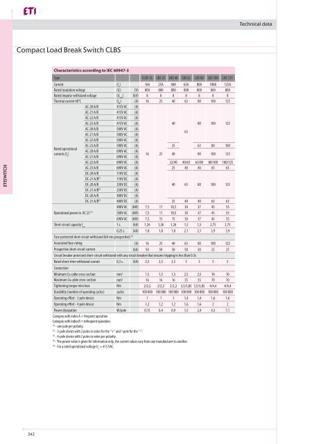
Technical data<br />
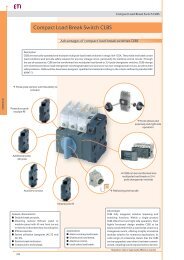
Compact Load Break Switch CLBS<br />
<strong>ETISWITCH</strong><br />
Characteristics according to IEC 60947-3<br />
Type<br />
Current<br />
Rated insulation voltage<br />
Rated impulse withstand voltage<br />
Thermal current 40°C<br />
Rated operational<br />
currents (l e<br />
)<br />
Operational power in AC 23 (4)<br />
Short-circuit capacity I cw<br />
AC-20 A/B<br />
AC-21 A/B<br />
AC-22 A/B<br />
AC-23 A/B<br />
AC-20 A/B<br />
AC-21 A/B<br />
AC-22 A/B<br />
AC-23 A/B<br />
AC-20 A/B<br />
AC-21 A/B<br />
AC-22 A/B<br />
AC-23 A/B<br />
DC-20 A/B<br />
DC-21 A/B (1)<br />
DC-20 A/B<br />
DC-21 A/B (2)<br />
DC-20 A/B<br />
DC-21 A/B (3)<br />
CLBS 16 LBS 25 LBS 40 LBS 63 LBS 80 LBS 100 LBS 125<br />
(I n<br />
) 16A 25A 40A 63A 80A 100A 125A<br />
(U i<br />
) (V) 800 800 800 800 800 800 800<br />
(U imp<br />
) (kV) 8 8 8 8 8 8 8<br />
(l th<br />
) (A) 16 25 40 63 80 100 125<br />
415V AC (A)<br />
415V AC (A)<br />
415V AC (A)<br />
415V AC (A)<br />
40<br />
80 100 125<br />
500V AC (A)<br />
500V AC (A)<br />
63<br />
500V AC (A)<br />
500V AC (A) 25 63 80 100<br />
690V AC (A)<br />
690V AC (A)<br />
16 25 40 80 100 125<br />
690V AC (A) 32/40 40/63 63/80 80/100 100/125<br />
690V AC (A) 25 40 40 63 63<br />
110V DC (A)<br />
110V DC (A)<br />
250V DC (A)<br />
40 63 80 100 125<br />
250V DC (A)<br />
400V DC (A)<br />
400V DC (A) 25 40 40 63 63<br />
400V AC (kW) 7,5 11 18,5 30 37 45 55<br />
500V AC (kW) 7,5 11 18,5 30 37 45 55<br />
690V AC (kW) 7,5 15 15 30 37 45 55<br />
1 s. (kA) 1,26 1,26 1,26 1,5 1,5 2,75 2,75<br />
0,25 s. (kA) 1,8 1,8 1,8 2,1 2,1 3,9 3,9<br />
Fuse protected short-circuit withstand (kA rms prospective) (5)<br />
Associated fuse rating<br />
(A) 16 25 40 63 80 100 125<br />
Prospective short-circuit current<br />
(kA) 50 50 50 50 50 25 25<br />
Circuit breaker protected short-circuit withstand with any circuit breaker that ensures tripping in less than 0.3s<br />
Rated short-time withstand current<br />
0,3 s. (kA) 2,5 2,5 2,5 3 3 5 5<br />
Connection<br />
Minimum Cu cable cross-section<br />
Maximum Cu cable cross-section<br />
Tightening torque min/max<br />
Durability (number of operating cycles)<br />
Operating effort - 3 pole device<br />
Operating effort - 4 pole device<br />
Power dissipation<br />
mm 2 1,5 1,5 1,5 2,5 2,5 10 10<br />
mm 2 16 16 16 35 35 70 70<br />
Nm 2/2,2 2/2,2 2/2,2 3,5/3,85 3,5/3,85 4/4,4 4/4,4<br />
cycles<br />
100 000 100 000 100 000 100 000 100 000 100 000 100 000<br />
Nm 1 1 1 1,4 1,4 1,6 1,6<br />
Nm 1,2 1,2 1,2 1,6 1,6 2 2<br />
W/pole<br />
0,15 0,4 0,9 1,5 2,4 4,3 7,1<br />
Category with index A = frequent operation<br />
Category with index B = infrequent operation.<br />
(1)<br />
- one pole per polarity.<br />
(2)<br />
- 3-pole device with 2 poles in series for the "+" and 1 pole for the "-".<br />
(3)<br />
- 4-pole device with 2 poles in series per polarity.<br />
(4)<br />
- The power value is given for information only, the current values vary from one manufacturer to another.<br />
(5)<br />
- For a rated operational voltage U e<br />
= 415 VAC.<br />
342
Technical data<br />
Dimensions<br />
CLBS 16 - CLBS 80 3P- direct operation with handle<br />
1. Location for: 1 switched fourth pole module (1 per<br />
device max.)<br />
or 1 unswitched neutral pole<br />
or 1 protective earth module<br />
or 1 auxiliary contact.<br />
2. Position for 1 auxiliary contact only.<br />
Note: max 2 additional blocks.<br />
More information about acceptable combinations of<br />
auxiliary switches and additional poles on the following<br />
page.<br />
Side view<br />
75<br />
64<br />
G<br />
68<br />
Front view<br />
2 1 F 1<br />
M 2<br />
N<br />
AC<br />
50<br />
6<br />
8.8<br />
F1<br />
M5<br />
T<br />
F1 8.8<br />
1. Location for: 1 switched fourth pole module (1 per<br />
device max.)<br />
or 1 unswitched neutral pole<br />
or 1 protective earth module<br />
or 1 auxiliary contact.<br />
2. Position for 1 auxiliary contact only.<br />
Note: max 2 additional blocks.<br />
More information about acceptable combinations of<br />
auxiliary switches and additional poles on the following<br />
page.<br />
80<br />
41<br />
B<br />
44<br />
36<br />
B. CLBS-EH125/01<br />
C. CLBS-EH80<br />
CLBS 16-CLBS 80<br />
External front operation<br />
Side view<br />
C<br />
E<br />
81<br />
64<br />
50.6<br />
50<br />
6<br />
36 D F<br />
D<br />
M<br />
2 1 1<br />
J<br />
2<br />
G<br />
68<br />
External side operation<br />
Front view<br />
N<br />
8.8 F1 F1 8.8<br />
T<br />
M5<br />
AC<br />
36<br />
ø 71<br />
<strong>ETISWITCH</strong><br />
Rating Оverall dimensions, (mm) Terminal<br />
shrouds,<br />
(А)<br />
D<br />
min<br />
D<br />
max<br />
E<br />
min<br />
E<br />
max<br />
(mm)<br />
AC<br />
Switch body, (mm)<br />
Switch<br />
mounting, (mm)<br />
Connection, (mm)<br />
F F1 G J M N T<br />
16-40 30 235 100 372 110 45 15 68 15 30 75 15<br />
63-80 30 235 100 372 110 52.5 17.5 76 17.5 35 85 17.5<br />
CLBS 100-CLBS 125 3P - direct operation with handle<br />
1. Location for: 1 switched fourth pole module (1 per<br />
device max.)<br />
or 1 unswitched neutral pole<br />
or 1 protective earth module<br />
or 1 auxiliary contact.<br />
2. Position for 1 auxiliary contact only.<br />
Note: max 2 additional blocks.<br />
More information about acceptable combinations of<br />
auxiliary switches and additional poles on the following<br />
page.<br />
Side view<br />
G<br />
Front view<br />
F<br />
1<br />
M<br />
2<br />
2 1<br />
N<br />
AC<br />
75<br />
64<br />
53<br />
6<br />
8.8 F1 T F1 8.8<br />
M5<br />
343
Technical data<br />
CLBS 100-CLBS 125<br />
External front operation<br />
External side operation<br />
Side view<br />
Front view<br />
80<br />
41<br />
A<br />
44<br />
37 E<br />
A. CLBS-EH125/01<br />
B. CLBS-EH125<br />
B<br />
81 64<br />
53<br />
50.6<br />
6<br />
37<br />
2<br />
D<br />
1<br />
G<br />
M F D 37<br />
J<br />
1<br />
2<br />
N<br />
AC<br />
8.8 F1 T F1 8.8<br />
M5<br />
ø 71<br />
88<br />
1. Location for: 1 switched fourth pole module (1 per<br />
device max.)<br />
or 1 unswitched neutral pole<br />
or 1 protective earth module<br />
or 1 auxiliary contact.<br />
2. Position for 1 auxiliary contact only.<br />
Note: max 2 additional blocks.<br />
More information about acceptable combinations of<br />
auxiliary switches and additional poles below.<br />
Rating Оverall dimensions, (mm)<br />
Terminal<br />
Switch<br />
Connection,<br />
Switch body, (mm)<br />
shrouds,<br />
mounting, (mm) (mm)<br />
(А) D D E E (mm) F F1 G J M N T<br />
min max min max AC<br />
100-125 30 201 100 372 189 78 26 124.6 13 26 131.4 26<br />
<strong>ETISWITCH</strong><br />
Auxiliary contact configurations CLBS-PS11<br />
(NO+NC)<br />
Max: 2 blocks / Max: 2 AC<br />
Pre-break<br />
No Pre-break<br />
Contact type Nominal current Operating current I e<br />
(А), 230V AC<br />
(A) AC-13 AC-15<br />
NO+NC 10 10 6<br />
Configuration additional pole, solid neutral pole<br />
and protective earth pole<br />
N or PE<br />
N or PE<br />
N or PE<br />
N or PE<br />
N or PE<br />
N or PE<br />
344
Technical data<br />
Direct operation<br />
CLBS 16 - CLBS 80 - with change over kit<br />
External front operation<br />
CLBS 16 - CLBS 80 - with change over kit<br />
2<br />
1<br />
X<br />
Side view<br />
F<br />
J<br />
F2<br />
M 52,5<br />
Front view<br />
89<br />
1 78<br />
2<br />
E<br />
B<br />
68<br />
N<br />
G<br />
45<br />
ø 71<br />
8,8<br />
F1<br />
T T 7,5<br />
52,5<br />
F1 8,8<br />
6<br />
43<br />
34,7<br />
36<br />
Rating Оverall dimensions, (mm) Switch body, (mm)<br />
2<br />
1<br />
X<br />
J<br />
F2<br />
M<br />
F<br />
52,5<br />
89<br />
Switch<br />
mounting, (mm)<br />
Connection,<br />
(mm)<br />
(А) E min E max F F1 F2 G J M N T X<br />
16-40 105 372 97.5 15 45 68 48.75 30 75 15 7.5<br />
63-80 105 372 105 17.5 52.5 76 52.5 35 85 17.5 8.75<br />
1 78<br />
E<br />
A<br />
2<br />
B<br />
C<br />
<strong>ETISWITCH</strong><br />
Direct front operation<br />
External front operation<br />
CLBS 100 - CLBS 125 -with change over kit<br />
N<br />
G<br />
68<br />
CLBS 100 - CLBS 125 -with change over kit<br />
45<br />
45<br />
ø 71<br />
80<br />
8,8<br />
F1<br />
Side view<br />
79.6<br />
T T 7,5<br />
M<br />
13.8 52,5<br />
F1 8,8<br />
1<br />
6<br />
2<br />
43 84.534,7<br />
50<br />
Front view<br />
E<br />
36<br />
25<br />
36<br />
44<br />
N<br />
G<br />
68<br />
ø 71<br />
F1<br />
8.8<br />
79.6<br />
T<br />
100<br />
6<br />
F<br />
Rating Оverall dimensions, (mm) Switch body, (mm)<br />
Switch mounting,<br />
(mm)<br />
Connection,<br />
(mm)<br />
(А) E min E max F F1 G M N T<br />
100-125 105 372 159 26 124.5 52.8 131.5 26<br />
345
Technical data<br />
CLBS-EH80<br />
(16-80A)<br />
Direct front<br />
operation<br />
I<br />
Right side<br />
operation<br />
I<br />
IP55 with 2 fixing<br />
clips<br />
40<br />
Door drilling<br />
IP65 with 4 fixing<br />
screws<br />
40<br />
Ø71<br />
90°<br />
90°<br />
2 Ø 7<br />
4 Ø 7<br />
71<br />
0<br />
0<br />
28<br />
28<br />
36<br />
Ø 37<br />
Ø 31<br />
<strong>ETISWITCH</strong><br />
CLBS-EH125<br />
(100-125A)<br />
Ø71<br />
88<br />
Direct front<br />
operation<br />
0<br />
90°<br />
I<br />
0<br />
Right side operation<br />
90°<br />
Door drilling<br />
IP55 with 2 fixing IP65 with 4 fixing<br />
clips<br />
screws<br />
I<br />
40<br />
40<br />
2 Ø 7<br />
4 Ø 7<br />
28<br />
28<br />
37<br />
Ø 37<br />
Ø 31<br />
CLBS-EH125/01<br />
(16-125A)<br />
Direct front<br />
operation<br />
Right side operation<br />
I<br />
I<br />
Ø78<br />
90°<br />
90°<br />
Ø 37<br />
40<br />
Door drilling<br />
80<br />
0<br />
0<br />
44<br />
41<br />
28<br />
4 Ø 7<br />
CLBS-EH80/G CO<br />
CLBS-EH125/G CO<br />
Direct front<br />
operation<br />
0<br />
or<br />
I+II<br />
Ø 37<br />
IP55 with 2 fixing<br />
clips<br />
Ø 37<br />
Door drilling<br />
IP65 with 4 fixing<br />
screws<br />
Ø 22.5<br />
13.5<br />
Ø71<br />
90°<br />
90°<br />
40<br />
40<br />
3<br />
71<br />
I<br />
II<br />
36<br />
28<br />
2 Ø 7<br />
28<br />
4 Ø 7<br />
346
Technical data<br />
Installation of accessories<br />
004661429<br />
004661430 004661426<br />
004661427<br />
004661400 / 004661401<br />
004661402 / 004661403<br />
004661404<br />
Direct operation<br />
004661432 / 004661433<br />
004661434 / 004661443<br />
004661446 / 004661435<br />
004661436 / 004661444<br />
004661447<br />
004661425<br />
Front operation<br />
Examples:<br />
Shaft 004661424<br />
CLBS-S400/01<br />
Terminal shrouds<br />
2 x 004661428 CLBS 100...125 3P<br />
(1 x top + 1 x bottom shrouds)<br />
CLBS body<br />
004661406 CLBS 125 3P<br />
Change over kit<br />
004661439 CLBS-CK80<br />
CLBS body<br />
2 x 00466140 CLBS 16 3P<br />
<strong>ETISWITCH</strong><br />
Front and right side handle<br />
004661417 CLBS-EH125/01G<br />
CLBS 16...80<br />
C<br />
L<br />
A<br />
16A - 40A<br />
60A - 80A<br />
Z<br />
B<br />
mm<br />
mm<br />
А 152 203<br />
B 203 254<br />
C 102 102<br />
Y 75 75<br />
E<br />
!<br />
16 A - 40 A<br />
60A - 80 A<br />
min.<br />
max.<br />
CLBS 100...125<br />
X<br />
X min: 25 mm<br />
Y<br />
203 mm<br />
6 mm<br />
min: 27 mm<br />
min. 5 mm<br />
153 mm<br />
X<br />
X min: 25 mm<br />
CLBS-EH80 L=X+32 mm 13 mm 15mm<br />
CLBS-EH125/01 L=X+38,5 mm 17,5 mm 21,5 mm<br />
356 mm<br />
min.<br />
E<br />
max.<br />
CLBS-EH125 L=X+94,5 mm 13 mm 15mm<br />
CLBS-EH125/01 L=X+101 mm 17,5 mm 21,5 mm<br />
min. 5 mm<br />
14,5 ±2,5 mm<br />
L<br />
E<br />
347
Technical data<br />
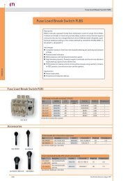
Load Break Switch LBS<br />
<strong>ETISWITCH</strong><br />
Characteristics according to IEC 60947-3<br />
Type<br />
Current<br />
Rated insulation voltage<br />
Rated impulse withstand voltage<br />
Thermal current 40°C<br />
Rated operational<br />
currents (l e<br />
)<br />
AC-20 A/B (1)<br />
AC-21 A/B (1)<br />
AC-22 A/B (1)<br />
AC-23 A/B (1)<br />
DC-20 A/B (1)<br />
DC-21 A/B (1)<br />
DC-22 A/B (1)<br />
DC-23 A/B (1)<br />
DC-20 A/B (1)<br />
DC-21 A/B (1)<br />
DC-22 A/B (1)<br />
DC-23 A/B (1)<br />
DC-20 A/B (1)<br />
DC-21 A/B (1)<br />
DC-22 A/B (1)<br />
DC-23 A/B (1)<br />
(1) (5)<br />
Operational power in AC 23<br />
Reactive power (5)<br />
Short-circuit capacity I cw<br />
LBS 160 LBS 250 LBS 400 LBS 630 LBS 800 LBS 1000 LBS 1250 LBS 1600 LBS 2000 LBS 2500 LBS 3200<br />
(I n<br />
) 160A 250A 400A 630A 800A 1000A 1250A 1600A 2000A 2500A 3200A<br />
(U i<br />
) (V) 800 800 1000 1000 1000 1000 1000 1000 1000 1000 1000<br />
(U imp<br />
) (kV) 8 8 12 12 12 12 12 12 12 12 12<br />
(l th<br />
) (A) 160 250 400 630 800 1000 1250 1600 2000 2500 3200<br />
415V AC (A) 160/160 250/250 400/400 630/630 800/800 1000/1000 1250/1250 1600/1600 2000/2000 2500/2500 3200/3200<br />
415V AC (A) 160/160 250/250 400/400 630/630 800/800 1000/1000 1250/1250 1600/1600 2000/2000 2500/2500 3200/3200<br />
415V AC (A) 160/160 250/250 400/400 630/630 800/800 1000/1000 1250/1250 1600/1600 2000/2000 2500/2500 2500/3200<br />
415V AC (A) 160/160 250/250 400/400 500/500 800/800 1000/1000 1250/1250 1250/1250 1600/1600 1600/1600 1600/1600<br />
220V DC (A) 160/160 250/250 400/400 630/630 800/800 1000/1000 1250/1250 1600/1600 2000/2000 2500/2500 3200/3200<br />
220V DC (A) 160/160 250/250 400/400 630/630 800/800 1000/1000 1250/1250 1250/1600 2000/2000 2000/2500 2000/2500<br />
220V DC (A) 160/160 250/250 400/400 500/500 800/800 1000/1000 1250/1250 1250/1250 1250/1600 1250/1600 1250/1600<br />
220V DC (A) 125/125 200/200 400/400 500/500 800/800 1000/1000 1250/1250 1250/1250 1250/1250 1250/1250 1250/1250<br />
440V DC (A) 160/160 250/250 400/400 630/630 800/800 1000/1000 1250/1250 1600/1600 2000/2000 2500/2500 3200/3200<br />
440V DC (A) 160 (3) /160 (3) 200 (3) /200 (3) 400 (3) /400 (3) 500 (3) /500 (3) 800 (4) /800 (4) 1000 (4) /1000 (4) 1250 (4) /1250 (4) 1250 (4) /1600 (4) 2000 (4) /2000 (4) 2000 (4) /2500 (4) 2500 (4) /3200 (4)<br />
440V DC (A) 125 (3) /125 (3) 200 (3) /200 (3) 400 (3) /400 (3) 500 (3) /500 (3) 800 (4) /800 (4) 1000 (4) /1000 (4) 1250 (4) /1250 (4) 1250 (4) /1250 (4) 1250 (4) /1250 (4) 1250 (4) /1250 (4) 1250 (4) /1250 (4)<br />
440V DC (A) 125 (4) /125 (4) 200 (4) /200 (4) 400 (4) /400 (4) 500/500 800 (4) /800 (4) 1000 (4) /1000 (4) 1250 (4) /1250 (4) 1250 (4) /1250 (4) 1250 (4) /1250 (4) 1250 (4) /1250 (4) 1250 (4) /1250 (4)<br />
500V DC (A) 160/160 250/250 400/400 630/630 800/800 1000/1000 1250/1250 1600/1600 2000/2000 2500/2500 3250/3250<br />
500V DC (A) 125 (3) /125 (3) 200 (3) /200 (3) 400 (3) /400 (3) 500 (3) /500 (3) 800 (4) /800 (4) 1000 (4) /1000 (4) 1250 (4) /1250 (4) 1250 (4) /1600 (4) 1250 (4) /1250 (4) 1250 (4) /1250 (4) 1250 (4) /1250 (4)<br />
500V DC (A) 125 (4) /125 (4) 200 (4) /200 (4) 315 (4) /400 (4) 500 (4) /500 (4) 800 (4) /800 (4) 1000 (4) /1000 (4) 1250 (4) /1250 (4) 1250 (4) /1250 (4) 1250 (4) /1250 (4) 1250 (4) /1250 (4) 1250 (4) /1250 (4)<br />
500V DC (A) 125 (4) /125 (4) 200 (4) /200 (4) 315 (4) /400 (4) 500 (4) /500 (4) 800 (4) /800 (4) 1000 (4) /1000 (4) 1250 (4) /1250 (4) 1250 (4) /1250 (4) 1000 (4) /1000 (4) 1000 (4) /1000 (4) 1000 (4) /1000 (4)<br />
415V AC (kW) 80/80 132/132 220/220 280/280 450/450 560/560 710/710 710/710 710/710 710/710 710/710<br />
400 V (kVAr) 75 115 185 290 365 460 - - - - -<br />
1 s. (kA) 7 9 13 13 35 35 35 50 50 50 50<br />
0,25 s. (kA) 11,9 15,3 26 26 73,5 73,5 73,5 75 80 80 80<br />
Fuse protected short-circuit withstand (kA rms prospective)<br />
Associated fuse rating (6)<br />
(A) 160 250 400 630 800 1000 1250 2х800 2х1000 2х1250 -<br />
Prospective short-circuit current<br />
(kA) 100 50 100 70 50 100 100 100 100 100 -<br />
Circuit breaker protected short-circuit withstand with any circuit breaker that ensures tripping in less than 0.3s<br />
Rated short-time withstand current I cw<br />
Connection<br />
Minimum Cu cable cross-section<br />
Maximum Cu cable cross-section<br />
Minimum Cu busbar cross-section<br />
Maximum Cu busbar width<br />
Tightening torque min/max<br />
Operating effort<br />
Durability (number of operating cycles)<br />
Power dissipation<br />
0,3 s. (kA) 15 17 25 25 50 65 65 100 100 100 100<br />
mm 2 50 95 185 2х150 2х185 2х240 - - - - -<br />
mm 2 95 150 240 2х300 2х300 4х185 4х185 4х185 - - -<br />
mm - - - 2х30х5 2х40х5 2х50х5 2х60х5 2х80х5 3х100х5 4х100х5 4х100х5<br />
mm 25 32 40 50 63 63 63 100 100 100 100<br />
Nm 9/- 20/- 20/- 20/- 40/45 40/45 40/45 40/45 40/45 40/- 40/-<br />
Nm 6,5 10 14,5 14,5 37 37 37 56 75 75 75<br />
cycles<br />
10 000 10 000 10 000 10 000 3 000 3 000 3 000 4 000 3 000 3 000 3 000<br />
W/pole<br />
3 5,8 10,8 30,9 39,7 42 80 122 140 205 340<br />
(1)<br />
Category with index A = frequent operation - Category with index B = infrequent operation.<br />
(2)<br />
With terminal shrouds or phase barrier.<br />
(3)<br />
3-pole device with 2 pole in series for the «+» and 1 pole for the «-».<br />
(4)<br />
4-pole device with 2 poles in series per polarity.<br />
(5)<br />
The power value is given for information only, the current values vary from one manufacturer to another.<br />
(6)<br />
For a rated operational voltage Ue = 415 VAC.<br />
348
Technical data<br />
Dimensions<br />
Direct front operation<br />
Front view<br />
LBS 160 - LBS 630<br />
External front operation<br />
Side view<br />
M<br />
J1 J 2<br />
Z<br />
Y<br />
1<br />
AC<br />
AA<br />
CA BA CA<br />
N<br />
W<br />
U1<br />
U<br />
V<br />
R<br />
90°<br />
0<br />
G<br />
K<br />
BC<br />
A<br />
125<br />
X1<br />
T<br />
I<br />
T<br />
F<br />
T<br />
X2<br />
AD<br />
H<br />
I. Terminal shrouds А.Handle type: LBS-EH630<br />
C<br />
18<br />
D min. 45<br />
Rating<br />
Оverall Terminal<br />
dimensions shrouds,<br />
(mm) (mm)<br />
(А) C D min AC AD F<br />
(3p)<br />
F<br />
(4p)<br />
Switch body, (mm)<br />
G H J1<br />
(3p)<br />
J1<br />
(4p)<br />
J2 K BC M<br />
(3p)<br />
Switch mounting,<br />
(mm)<br />
M<br />
(4p)<br />
N R T U U1 V W X1<br />
(3p)<br />
Connection, (mm)<br />
X1<br />
(4p)<br />
X2 Y Z AA BA CA<br />
160<br />
235 50 140 170 93 65 45 75 75 31.5 80 120 150 65 5.5 36 20 20.5 25 9 28 22 20 3.5 20.5 135 115 10<br />
115 125<br />
250 280 60 180 230 108 75 55 105 105 34 115 160 210 80 5.5 50 20 25.5 21.5 11 33 33 27 3.5 22.5 160 130 15<br />
400<br />
32<br />
29 11<br />
235 205 15<br />
160 165 401 89 230 290 170 110 75 135 135 55 115 210 270 140 7 65 45.5<br />
42.5 37.5 37.5 5 36<br />
630 45 41.5 13 260 220 20<br />
<strong>ETISWITCH</strong><br />
LBS 800 - LBS 1600<br />
Direct front operation<br />
Front view<br />
M<br />
= =<br />
Z<br />
Y 1<br />
External front operation<br />
Side view<br />
B<br />
U<br />
Min. 221<br />
470<br />
AA<br />
= 175 =<br />
V<br />
90<br />
0<br />
28<br />
ø9<br />
330<br />
= =<br />
350<br />
X1<br />
T<br />
I<br />
T<br />
F<br />
T<br />
X2<br />
86<br />
140 26<br />
166 49<br />
215 14<br />
60<br />
I. Terminal shrouds<br />
B. Handle type: LBS-EH1600<br />
Rating Switch body, (mm) Switch mounting, (mm) Connection, (mm)<br />
(А)<br />
F<br />
(3p)<br />
F<br />
(4p)<br />
M<br />
(3p)<br />
M<br />
(4p)<br />
T U V Y X1 X2 Z AA<br />
800 - 1000<br />
50 60.5<br />
321<br />
280 360 255 335 80<br />
7 47.5 47.5 46.5<br />
1250 60 65 330<br />
1600 372 492 492 467 120 90 44 8 53.5 53.5 47.5 288<br />
349
Technical data<br />
Direct front operation<br />
Front view<br />
A<br />
LBS 2000 - LBS 3200<br />
External front operation<br />
Side view<br />
U<br />
M<br />
Y<br />
226<br />
Y<br />
L = x-295 mm<br />
250<br />
BA<br />
380<br />
498<br />
498<br />
97<br />
J T<br />
181<br />
71<br />
X<br />
71<br />
Handle type: LBS-EH3200<br />
<strong>ETISWITCH</strong><br />
Rating Оverall dimensions, (mm) Switch body, (mm) Switch mounting, (mm) Connection, (mm)<br />
(А)<br />
A<br />
(3p)<br />
A<br />
(4p)<br />
J<br />
(3p)<br />
J<br />
(4p)<br />
M<br />
(3p)<br />
M<br />
(4p)<br />
T U Y BA<br />
2000-3200 372 492 173.5 233.5 347 367 120 90 8 258<br />
Handle type LBS-EH630 Direct front operation Door drilling<br />
0<br />
40<br />
Ø78<br />
90°<br />
125<br />
I<br />
4 Ø 7<br />
28<br />
45<br />
Ø 37<br />
Handle type LBS-EH1600 Direct front operation Door drilling<br />
Ø78<br />
O<br />
90°<br />
Ø 37<br />
350<br />
I<br />
40<br />
28<br />
4 Ø 7<br />
60<br />
Handle type LBS-EH3200 Direct front operation Door drilling<br />
90°<br />
50<br />
I<br />
4 Ø 6,5<br />
498<br />
0<br />
50<br />
Ø 31<br />
71<br />
102<br />
350
Technical data<br />
Rating<br />
(А)<br />
LBS 160<br />
LBS 250<br />
LBS 400-630<br />
LBS 800-1600<br />
LBS 2000-3200<br />
Dimension Х<br />
(mm)<br />
Shaft length<br />
(mm)<br />
125 - 250 200<br />
125 - 370 320<br />
125 - 550 500<br />
135 - 265 200<br />
135 - 385 320<br />
135 - 565 500<br />
165 - 295 200<br />
165 - 415 320<br />
165 - 595 500<br />
221 - 343 200<br />
221 - 463 320<br />
221 - 543 400<br />
415 - 570 200<br />
415 - 690 320<br />
415 - 820 450<br />
Rating<br />
(А)<br />
X<br />
U, (mm) V, (mm) W, (mm)<br />
160 20 25 9<br />
250 25 21.5 11<br />
400 32 29 11<br />
630 45 41.5 13<br />
Connection terminal<br />
dimensions:<br />
V<br />
U<br />
LBS-160-630<br />
W<br />
Rating<br />
(А)<br />
U, (mm) V, (mm) W1, (mm) W2, (mm) X1, (mm) X2, (mm) Y, (mm)<br />
800 - 1000 50 60.5 9 16 28.5 11 33<br />
V<br />
Y<br />
X2 X1 X2<br />
U<br />
LBS-800-1000<br />
4x ø W1<br />
ø W2<br />
<strong>ETISWITCH</strong><br />
4x ØW<br />
Rating<br />
(А)<br />
U, (mm) V1, (mm) V2, (mm) W, (mm) X1, (mm) Y, (mm)<br />
1250 60 65 28.5 16 28.5 11<br />
V1<br />
X1<br />
U<br />
V2<br />
Y<br />
LBS-1250<br />
ø W<br />
Rating<br />
(А)<br />
U, (mm) V1, (mm) V2, (mm) W, (mm) X1, (mm) X2, (mm) X3, (mm) Y, (mm)<br />
1600-3200 90 35.8 15 12.5 25 30 45 12.5<br />
Y<br />
X1<br />
X2<br />
X3<br />
U<br />
X1<br />
X2<br />
X3<br />
V2<br />
V1<br />
LBS-1600-3200<br />
LBS-PS11 Auxiliary contact (change over NO/NC)<br />
Rating<br />
(А)<br />
Contact<br />
type<br />
Current<br />
nominal (А)<br />
Operating current I e<br />
(A)<br />
230 V AC 400 V AC 24 V DC 48 V DC<br />
AC-12 AC-13/15 AC-12 AC-13/15 DC-12 DC-13 DC-14 DC-12 DC-13 DC-14<br />
160-3200 CO 16 16 4 12 3 2,5 2,5 1 2,5 1,2 0,2<br />
351
Technical data<br />
Installation of accessories<br />
LBS body<br />
LBS 3P<br />
Terminal screen<br />
LBS-TS<br />
Terminal shrouds<br />
LBS-TS<br />
<strong>ETISWITCH</strong><br />
Auxiliary contact*<br />
LBS-PS11<br />
Direct handle<br />
LBS-DH<br />
Shaft<br />
LBS-S<br />
Door interlocked handle<br />
LBS-EH<br />
*Only one auxiliary contact can be mounted to each switch body<br />
352
Technical data<br />
Load Break Change Over Switch LBS..CO<br />
Characteristics according to IEC 60947-3, IEC 60947-6-1:<br />
Type<br />
Current<br />
Rated insulation voltage<br />
Rated impulse withstand voltage<br />
Thermal current 40°C<br />
Rated operational<br />
currents (l e<br />
)<br />
IEC 60947-3<br />
Rated operational<br />
currents (l e<br />
)<br />
IEC 60947-6-1<br />
(4)<br />
Data at 415 VAC<br />
(5)<br />
Data at 30 ms<br />
AC-20 A/B<br />
AC-21 A/B<br />
AC-22 A/B<br />
AC-23 A/B<br />
AC-20 A/B<br />
AC-21 A/B<br />
AC-22 A/B<br />
AC-23 A/B<br />
AC-20 A/B<br />
AC-21 A/B<br />
AC-22 A/B<br />
AC-23 A/B<br />
DC-20 A/B (1)<br />
DC-21 A/B (1)<br />
DC-22 A/B (1)<br />
DC-23 A/B (1)<br />
DC-20 A/B (1)<br />
DC-21 A/B (1)<br />
DC-22 A/B (1)<br />
DC-23 A/B (1)<br />
AC-31 A/B<br />
AC-32 A/B<br />
AC-33 A/B<br />
Short-circuit capacity I cw<br />
, 690 V AC<br />
I cw<br />
, 415 V AC according to IEC 60947-6-1<br />
Operational power in AC 23 (2)<br />
Reactive power<br />
Fuse protected short-circuit withstand (kA rms prospective), 690 V AC<br />
Associated fuse rating<br />
Prospective short-circuit current<br />
LBS 160 LBS 250 LBS 400 LBS 630 LBS 800 LBS 1000 LBS 1250 LBS 1600 LBS 2000 LBS 2500 LBS 3200<br />
(I n<br />
) 160A 250A 400A 630A 800A 1000A 1250A 1600A 2000A 2500A 3200A<br />
(U i<br />
) (V) 800 1000 1000 1000 1000 1000 1000 1000 1000 1000 1000<br />
(U imp<br />
) (kV) 8 12 12 12 12 12 12 12 12 12 12<br />
(l th<br />
) (A) 160 250 400 630 800 1000 1250 1600 2000 2500 3200<br />
415V AC (A)<br />
415V AC (A)<br />
250<br />
1600 2000 2500 3200<br />
415V AC (A)<br />
400 630 800 1000 1250<br />
415V AC (A) 160 200 1250 1600 1600 1600<br />
500V AC (A)<br />
250<br />
500V AC (A)<br />
1600<br />
2000 2500 3200<br />
500V AC (A) 200/250 200/400 500 630 800 1000 - - -<br />
500V AC (A) 80 200 200 400 400 630 800 1000 - - -<br />
690V AC (A)<br />
250 400 630<br />
160<br />
690V AC (A) 200 200 500<br />
800 1000 1250 1600 2000 2500 3200<br />
690V AC (A) 125 160 160<br />
630 800 1000 1000 - - -<br />
400<br />
690V AC (A) 63/80 125 125 400 630 800 800 - - -<br />
220V DC (A)<br />
400<br />
1600 - - -<br />
220V DC (A) 160 250<br />
- - -<br />
250<br />
220V DC (A) 1250<br />
- - -<br />
220V DC (A) 125 200 200 630<br />
- - -<br />
800 1000 1250<br />
440V DC (A) 160 250 400 1600 - - -<br />
440V DC (A)<br />
- - -<br />
440V DC (A) 125 200 200 1250<br />
- - -<br />
440V DC (A) 500 - - -<br />
415V AC (A) 160 250 400 630 800 1000 1250 1600 2000 2500 3200<br />
415V AC (A) 200 400 500 800 1000 1250 1600 2000 2000 2000<br />
415V AC (A) 200 200 400 800 800 800 1000 1250 1250 1250<br />
1 s. (4) (kA) 7 8 8 10 26 35 35 50 50 50 50<br />
0,25 s. (kA) 11,9 22 22 17 48 73,5 73,5 110 110 110 110<br />
0,06 s. (5) (kA) 10 10 12,6 16 20 25 32 40 50 50<br />
(400V) (kW) 80 132 280 450 450 560 710 710 710 - -<br />
(690V) (kW) 55/75 90/110 150/185 185/220 185/220 475 475 750 750 - -<br />
400 V (kVAr) 75 115 185 290 365 460 575 - - - -<br />
(A) 160 250 400 630 800 1000 1250 2х800 - - -<br />
(kA) 100 50 50 50 50 100 100 100 100 100 -<br />
Circuit breaker protected short-circuit withstand with any circuit breaker that ensures tripping in less than 0.3s (3)<br />
Rated short-time withstand current I cw 0,3 s. (kA) 12 15 15 17 47 64 64 78 78 78 78<br />
Connection<br />
Minimum Cu cable cross-section<br />
mm 2 50 95 185 2х150 2х185 2х240 - - - - -<br />
Maximum Cu cable cross-section<br />
mm 2 95 150 240 2х300 2х300 4х185 4х185 4х185 - - -<br />
Minimum Cu busbar cross-section<br />
mm - - - 2х30х5 2х40х5 2х50х5 2х60х5 2х80х5 2х100х10 2х100х10 4х100х10<br />
Maximum Cu busbar width (Cu)<br />
mm 25 32 32 50 63 63 63 100 100 100 100<br />
Tightening torque min/max<br />
Nm 9/13 20/26 20/26 20/26 20/26 20/26 20/26 40/45 40/45 40/45 40/45<br />
Durability (number of operating cycles) cycles<br />
10 000 8 000 5 000 5 000 4 000 4 000 4 000 3 000 3 000 3 000 3 000<br />
Power dissipation<br />
W/pole<br />
3,2 6 15,5 35 40 52,2 80 95 - - -<br />
Category with index A = frequent operation<br />
Category with index B = infrequent operation.<br />
(1)<br />
3-pole device with 2 poles in series for the „+” and 1 pole for the „-”, 4-pole device with 2 poles in series per polarity.<br />
(2)<br />
The power value is given for information only, the current values vary from one manufacturer to another.<br />
(3)<br />
Value for coordination with any circuit breaker that ensures tripping in less than 0.3s.<br />
<strong>ETISWITCH</strong><br />
353
Technical data<br />
Dimensions<br />
Direct front operation<br />
Front view<br />
LBS 160 CO - LBS 1600 CO 3/4 p<br />
External front operation<br />
Side view<br />
А. Handle type LBS-EH630 CO for external operation:<br />
160 to 630 A<br />
B. Handle type LBS-EH1600 CO for external operation:<br />
800 to 1600 A<br />
I. Terminal shrouds<br />
II. Direct handle operation:<br />
- L1 = 140 мм: 160 to 630 A;<br />
- L1 = 210 мм: 800 to 1600 A;<br />
<strong>ETISWITCH</strong><br />
Rating<br />
(А)<br />
A<br />
(3p)<br />
Оverall dimensions, (mm)<br />
A<br />
(4p)<br />
Terminal<br />
shrouds,<br />
(mm)<br />
Switch body, (mm)<br />
C E min AC H HA J<br />
(3p)<br />
J<br />
(4p)<br />
Switch mounting,<br />
(mm)<br />
M<br />
(3p)<br />
M<br />
(4p)<br />
N T U V W X<br />
(3p)<br />
Connection, (mm)<br />
X<br />
(4p)<br />
Y Z Z1 AA BA CA<br />
160 221 251 218 208 - 436 235 148 25 182 212 156 186 101 36 20 25 8.5 56 50 3.5 28 124 135 115 10<br />
250 262 312 218 208 - 436 280 148 25 223 273 196 246 116 50 25 30 11 61 61 3.5 30 124 160 130 15<br />
400 262 312 218 208 - 436 280 148 25 223 273 196 246 116 50 35 35 11 61 61 3.5 30 124 170 140 15<br />
630 319 379 295 285 - 513 400 225 25 272 332 246 306 176 65 45 50 13 70.5 65.5 5 43 180 260 220 20<br />
800 386 466 375 425 - 577 459 298 29 306.5 386.5 255 336 250 80 50 60.5 15 48 48 7 66.5 253.5 321 26.5<br />
1000 386 466 375 425 - 577 459 298 29 306.5 386.5 255 336 250 80 50 60.5 15 48 48 7 66.5 253.5 321 26.5<br />
1250 386 466 375 425 - 577 459 298 29 306.5 386.5 255 336 250 80 60 65 16x11 48 48 7 66.5 255.5 330 29.5<br />
1600 478 598 375 425 - 577 461 298 29 388.5 518.5 347 467 250 120 90 43.5 12.5x5 54 54 8 66.5 255.5 288 15<br />
Direct front operation<br />
Front view<br />
A<br />
M 51.5<br />
LBS 2000 CO - LBS 3200 CO 3/4 P<br />
436.5<br />
Side view<br />
461<br />
258<br />
250<br />
380<br />
498<br />
498<br />
120<br />
120<br />
120<br />
53.5<br />
425<br />
71<br />
425<br />
71<br />
102<br />
653<br />
Rating<br />
(А)<br />
A, (mm)<br />
(3p)<br />
2000-3200 478 598 347 467<br />
A, (mm)<br />
(4p)<br />
Connection terminals<br />
M, (mm)<br />
(3p)<br />
M, (mm)<br />
(4p)<br />
LBS 800 3/4 P СО LBS 1250 3/4 P СО LBS 1600 - 3200 3/4 P СО<br />
ø 9<br />
16 x 11<br />
ø12.5<br />
5 5<br />
12.5<br />
ø 15<br />
8.5<br />
10 33<br />
33 8.5<br />
50<br />
15.75<br />
15 28.5<br />
28.5 15.75<br />
60<br />
25 25<br />
30 30<br />
45 45<br />
90<br />
15<br />
354
90°<br />
Technical data<br />
Handle type LBS-EH630 CO<br />
for LBS 160 - 630 3/4P CO<br />
Direct front operation<br />
0<br />
or<br />
I+II<br />
Door drilling<br />
20 20<br />
Ø78<br />
90°<br />
90°<br />
4 Ø 7<br />
125<br />
I<br />
II<br />
1414<br />
45<br />
Ø D<br />
(1)<br />
(1) Ø31 to Ø37: rear screw mounting Ø37: front clip mounting<br />
Handle type LBS-EH1600 CO<br />
for LBS 800 - 1600 3/4P CO<br />
Ø78<br />
Direct front operation<br />
350<br />
I<br />
90°<br />
0<br />
or<br />
I+II<br />
90°<br />
II<br />
20 20<br />
4 Ø 7<br />
<strong>ETISWITCH</strong><br />
60<br />
(1) Ø31 to Ø37: rear screw mounting Ø37: front clip mounting<br />
(2) Ø6 to Ø7: clip mounting<br />
II<br />
50<br />
90°<br />
4 Ø 6.5<br />
0<br />
50<br />
1414<br />
(2)<br />
Ø D<br />
(1)<br />
Handle type LBS-EH3200 CO<br />
for LBS 2000 - 3200 3/4P CO<br />
Direct front operation<br />
Door drilling<br />
498<br />
71<br />
102<br />
I<br />
Ø 31<br />
X<br />
Rating<br />
(А)<br />
160 - 400<br />
500 - 630<br />
800 - 1800<br />
2000 - 3200<br />
Dimension Х<br />
(mm)<br />
Length<br />
(mm)<br />
210 - 310 200<br />
210 - 430 320<br />
280 - 390 200<br />
280 - 510 320<br />
425 - 577 200<br />
425 - 697 320<br />
653 - 803 320<br />
653 - 923 320<br />
653 - 1053 450<br />
355
Technical data<br />
Installation of accessories<br />
Terminal shroud<br />
004661502 LBS-TS630 3P<br />
LBS CO body<br />
004661553 LBS 630 3P CO<br />
Shaft 004661490<br />
LBS-S200/630 (CO) …/400 FLBS<br />
<strong>ETISWITCH</strong><br />
Connection LBS 2000-3200A CO<br />
Enables:<br />
• To allow connection between the two power terminals from a same pole for 2000 to 3200A ratings (Fig. 1 and Fig 2)<br />
• Top or bottom bridging connection (Fig. 3).<br />
For 3200 A rating, the connection pieces (part A) are delivered bridged from factory. Bolt sets must be ordered separately.<br />
Door interlocked handle<br />
004661582 LBS-EH630/G CO<br />
Current<br />
(А)<br />
Piece Quantity to order per pole (1) Code No.<br />
2000 - 2500 Bridging bar part A<br />
2 004661597<br />
2000 - 2500 Bolt set - part B<br />
2 004661598<br />
3200<br />
Bridging bar part A<br />
included<br />
3200 Bolt set - part B<br />
2 004661598<br />
74<br />
37<br />
252<br />
74<br />
37 60<br />
129<br />
155<br />
Current<br />
(А)<br />
Piece Quantity to order per pole (1) Code No.<br />
2000 - 2500 Bridging bar part A<br />
2 004661597<br />
2000 - 2500 T piece - part C<br />
2 004661599<br />
2000 - 2500 Right angle - part D<br />
2 004661600<br />
Fig. 1<br />
3200<br />
Bridging bar part A<br />
included<br />
3200 T piece - part C<br />
2 004661599<br />
3200 Right angle - part D<br />
2 004661600<br />
C<br />
D<br />
A<br />
Current<br />
(А)<br />
Piece Quantity to order per pole (1) Code No.<br />
2000 - 2500 Bridging bar part A<br />
2 004661597<br />
2000 - 2500 Bolt set - part B<br />
2 004661598<br />
2000 - 2500 Bar - piece E<br />
1 004661601<br />
2000 - 2500 T piece - part C<br />
1 004661599<br />
30303030 132 30303030 22<br />
3200<br />
3200<br />
Bridging bar part A<br />
Bolt set - part B<br />
2<br />
included<br />
004661598<br />
3200 Bar - piece E<br />
1 004661602<br />
3200 T piece - part C<br />
1 004661599<br />
210<br />
C<br />
Fig. 2<br />
E<br />
B<br />
30303030 148<br />
225<br />
A<br />
Fig. 3<br />
356
Technical data<br />
Motorised Change Over Load Break Switch MLBS..CO (1-0-2)<br />
Characteristics according to IEC 60947-3, IEC 60947-6-1<br />
Type<br />
Current<br />
Rated insulation voltage (power circuit)<br />
Rated insulation voltage (operation circuit)<br />
Rated impulse withstand voltage (power circuit)<br />
Rated impulse withstand voltage (operation circuit)<br />
Thermal current 40°C<br />
Rated operational currents (l e<br />
)<br />
according to IEC 60947-3<br />
Rated operational currents (l e<br />
)<br />
according to IEC 60947-6-1<br />
Short-circuit capacity I cw<br />
AC-20A/B<br />
AC-21A/B<br />
AC-22A/B<br />
AC-23A/B<br />
AC-31B<br />
AC-32B<br />
Fuse protected short-circuit withstand (kA rms prospective)<br />
Associated fuse rating<br />
Prospective short-circuit current<br />
MLBS 63 CO MLBS 100 CO MLBS 125 CO<br />
(I n<br />
) (A) 63A 100A 125A<br />
(U i<br />
) (V) 800 800 800<br />
(U i<br />
) (V) 300 300 300<br />
(U ) imp (kV) 6 6 6<br />
(U ) imp (kV) 4 4 4<br />
(l th<br />
) (A) 63 100 125<br />
415V<br />
(A)<br />
125<br />
415V (A) 63 100 100/125<br />
415V (A) 100<br />
415V (A) -/63 -/63 -/63<br />
415V (A) 63 100 125<br />
415V (A) 63 80 80<br />
1 s. (kA) 2,5 2,5 2,5<br />
0,25 s. (kA) 4,5 4,5 4,5<br />
(A) 63 100 125<br />
(kA) 50 25 15<br />
Circuit breaker protected short-circuit withstand with any circuit breaker that ensures tripping in less than 0.3s (1)<br />
Rated short-time withstand current I cw<br />
Connection<br />
Maximum Cu cable cross-section<br />
Tightening torque min/max<br />
Switching time (Standard setting)<br />
1-0 or 2-0<br />
1-2 or 2-1<br />
Duration of '''electrical blackout' 1-2 minimum<br />
Power supply<br />
Power supply 12 V DC min/max<br />
Power supply 230 V AC min/max<br />
Control supply power demand<br />
Power supply 12 V DC inrush/nominal<br />
Power supply 230 V АC inrush/nominal<br />
Durability (number of operating cycles)<br />
Power dissipation<br />
(1)<br />
Value for coordination with any circuit breaker that ensures tripping in less than 0.3s.<br />
0,3 s. (kA) 3,5 3,5 3,5<br />
mm 2 50 50 50<br />
Nm 1,2/3 1,2/3 1,2/3<br />
(ms) 500 500 500<br />
(ms) 1000 1000 1000<br />
(ms) 500 500 500<br />
(V) 9/15 9/15 9/15<br />
(V) 160/310 160/310 160/310<br />
(VA) 200/40 200/40 200/40<br />
(VA) 200/40 200/40 200/40<br />
cycles<br />
10 000 10 000 10 000<br />
W/pole<br />
1,7 4,5 6<br />
<strong>ETISWITCH</strong><br />
357
Technical data<br />
Dimensions<br />
MLBS 63 4P CO - MLBS 125 4P CO<br />
Front view<br />
Side view<br />
Connection terminal<br />
<strong>ETISWITCH</strong><br />
Power supply MLBS 63 - MLBS125 4P CO 230VAC<br />
1 - preferred source<br />
2 - alternate source<br />
1 - position 0 control<br />
2 - position І control<br />
3 - position ІІ control<br />
4 - auxiliary contact, closed when the switch is in<br />
position 0<br />
5 - auxiliary contact, closed when the switch is in<br />
position ІІ<br />
6 - auxiliary contact, closed when the switch is in<br />
position І<br />
7 - power supply kit: 230 V АС (160 - 310 V АС)<br />
MLBS 63...125 4P CO 230VAC<br />
MLBS 63...125 4P CO 12VDC<br />
1 - preferred source<br />
2 - alternate source<br />
1 - position 0 control<br />
2 - position І control<br />
3 - position ІІ control<br />
4 - auxiliary contact, closed when the switch is in<br />
position 0<br />
5 - auxiliary contact, closed when the switch is in<br />
position ІІ<br />
6 - auxiliary contact, closed when the switch is in<br />
position І<br />
7 - power supply 12 V DC (9 - 15 V DС)<br />
358
Technical data<br />
Fuse Load Break Switch FLBS<br />
Characteristics according to IEC 60947-3<br />
Type<br />
FLBS 125 FLBS 160 FLBS 250 FLBS 400 FLBS 630<br />
Current<br />
(I n<br />
) (A) 125A 160A 250A 400A 630A<br />
Rated insulation voltage<br />
(U i<br />
) (V) 750 750 750 1000 1000<br />
Rated impulse withstand voltage<br />
(U )<br />
imp<br />
(kV) 8 8 8 12 12<br />
NFC/DIN fuse size<br />
00/00 C 00/00 C 1 2 3<br />
Thermal current 40°C<br />
(l th<br />
) (A) 125 160 250 400 630<br />
AC-22A/B<br />
400V (A)<br />
AC-23A/B<br />
400V (A) 125 160<br />
400<br />
630<br />
AC-22A/B (1)<br />
690V (A) 500/630<br />
AC-23A/B (1)<br />
690V (A) 100 125 250 315/400 315/400<br />
Rated operational currents (l e<br />
)<br />
DC-20A/B<br />
220V (A)<br />
400<br />
400/630<br />
DC-21A/B<br />
220V (A) 125 160<br />
315<br />
DC-22A/B<br />
220V (A) 315/630<br />
DC-23A/B<br />
220V (A) 100 125 200 200/315<br />
(2) (3)<br />
DC-20A/B 440V (A)<br />
400 400/630<br />
(2) (3)<br />
DC-21A/B 440V (A) 125 160 250<br />
315<br />
(2) (3)<br />
DC-22A/B 440V (A) 315/630<br />
(2) (3)<br />
DC-23A/B 440V (A) 100 125 200 250/315 400/630<br />
Operational power in AC 23 (4)<br />
400V AC kW 63 80 132 220 355<br />
690V AC kW 90 110 220 220/295 295/400<br />
Reactive power (4)<br />
400 V AC (kVAr) 55 75 115 185 290<br />
Fuse protected short-circuit withstand (kA rms prospective)<br />
Associated fuse rating 5)<br />
(A) 125 160 250 400 630<br />
Prospective short-circuit current (5)<br />
(kA) 100 50 100 100 100<br />
Short-circuit capacity<br />
Rated peak withstand current<br />
0,3 s. (kA) 20 20 32,5 40 70<br />
Connection<br />
Minimum Cu cable cross-section<br />
Maximum Cu cable cross-section<br />
Maximum Cu busbar width (Cu)<br />
Tightening torque min/max<br />
Durability (number of operating cycles)<br />
Power dissipation<br />
mm 2 35 35 95 185 2x150<br />
mm 2 95 95 240 240 2x300<br />
mm 20 20 32 45 63<br />
Nm 8.3/13 8.3/13 20/26 20/26 40/45<br />
cycles<br />
10 000 10 000 10 000 10 000 80 000<br />
W/pole<br />
20,3 21,6 41,1 57,4 122<br />
(mm) 36 36 60 66 94<br />
Frame pitch<br />
Category with index A = frequent operation; Category with index B = infrequent operation.<br />
(1)<br />
- With terminal shrouds or terminal screen.<br />
(2)<br />
- Poles cannot be juxtaposed.<br />
(3)<br />
- 4-pole device with 2 poles in series per polarity.<br />
(4)<br />
- The power value is given for information only, the current values vary from one manufacturer to another.<br />
(5)<br />
- For a rated operational voltage Ue = 415 VAC.<br />
<strong>ETISWITCH</strong><br />
Characteristics FLBS-PS<br />
Rating<br />
(А)<br />
250 V AC<br />
AC-15<br />
400 V AC<br />
AC-15<br />
Operating current I e<br />
(A)<br />
24 V DC<br />
DC-13<br />
125-630 3 1,8 2,8 1,4<br />
48 V DC<br />
DC-13<br />
Shaft lenghts<br />
Rating (А)<br />
Fuse size<br />
125-160 250-400 630<br />
00 1/2 3<br />
Shaft length (mm)<br />
X X X<br />
200 135 - 230 160 - 230 270 - 304<br />
320 135 - 350 160 - 350 270 - 424<br />
400 135 - 430 160 - 430 270 - 504<br />
500 135 - 530 160 - 530 270 - 604<br />
X<br />
359
Technical data<br />
Dimensions<br />
FLBS 125...160 3P<br />
Top view<br />
Side view<br />
Front view<br />
<strong>ETISWITCH</strong><br />
1 - Auxiliary contact<br />
2 - Terminal shrouds<br />
FLBS 250 3P<br />
Top view<br />
Side view<br />
Front view<br />
1 - Auxiliary contact<br />
2 - Terminal shrouds<br />
360
Technical data<br />
FLBS 400 3P<br />
Top view<br />
Side view<br />
Front view<br />
<strong>ETISWITCH</strong><br />
1 - Auxiliary contact<br />
2 - Terminal shrouds<br />
FLBS 630 3P<br />
Top view<br />
1<br />
Side view<br />
364 (3Р)<br />
458 (4Р)<br />
Front view<br />
min. 265<br />
250<br />
155<br />
284 (3Р)<br />
378 (4Р)<br />
65<br />
34<br />
79.5<br />
11<br />
297<br />
235.5<br />
90 7 90<br />
471<br />
300<br />
fix. 250<br />
260<br />
7<br />
235.5<br />
2<br />
7<br />
85.5<br />
Ø 13<br />
9<br />
380<br />
59<br />
51<br />
94 94<br />
1 -Auxiliary contact<br />
2 - Terminal shrouds<br />
361
Technical data<br />
Handle type LBS-EH630/G ...400/G FLBS Direct front operation Door drilling<br />
TEST<br />
65°<br />
0<br />
90°<br />
20 20<br />
4 Ø 7<br />
Ø78<br />
I<br />
14<br />
Ø 37<br />
<strong>ETISWITCH</strong><br />
Ø78<br />
0<br />
90°<br />
I<br />
20 20<br />
4 Ø 7<br />
210<br />
14<br />
125<br />
14<br />
45<br />
Handle type LBS-EH630/G Direct front operation Door drilling<br />
14<br />
Ø 37<br />
61<br />
Installation of accessories<br />
FLB body<br />
004661804 FLBS 630 3P<br />
Terminal shrouds<br />
2x004661830 FLBS-TS630 3P<br />
Shaft<br />
004661821 FLBS-S320/630<br />
Door interlocked handle<br />
004661823 FLBS-EH630/G<br />
362
Technical data<br />
Rotary Cam Switches<br />
Technical data<br />
Type<br />
Rated insulation voltage<br />
Rated impulse withstand voltage<br />
Rated thermal current<br />
Main switch<br />
IEC 60947 (III/3)<br />
U i<br />
U imp<br />
I th<br />
Max. value of rated operational voltage<br />
Rated impulse withstand voltage<br />
Max. fuse size for short-circuit protection gL 10kA<br />
Rated short-time<br />
withstand current I cw<br />
Rated operational current I e<br />
AC1/AC21<br />
Rated operational current<br />
I e<br />
AC15<br />
Motor switch in utilisation<br />
category<br />
AC3/AC23<br />
Motor switch in utilisation<br />
category<br />
AC4<br />
Mechanical endurance<br />
Terminal screw<br />
Screw head<br />
Tightening torque<br />
Cable cross-section<br />
3 phase<br />
1 phase<br />
2 poles<br />
3 phase<br />
Protection degree of terminals<br />
Permissible ambient temperature<br />
Standards<br />
switching cycles<br />
1 sec<br />
3 sec<br />
10 sec<br />
30 sec<br />
60 sec<br />
110/120 V<br />
220/230 V<br />
380/400 V<br />
660/690 V<br />
220/230 V<br />
380/400 V<br />
500/690 V<br />
110/120 V<br />
220/230 V<br />
380/400 V<br />
220/230 V<br />
380/400 V<br />
500/690 V<br />
Rigid<br />
Flexible<br />
CS 10 CS 16 CS 25 CS 32 CS 40 CS 63 CS 80 CS 100<br />
V 400 400 690 690 690 690 690 690<br />
kV 4 4 6 6 6 6 6 6<br />
A 16 20 25 32 50 70 85 100<br />
V 400 400 480 480 480 480 480 480<br />
kV 4 4 4 4 4 4 4 4<br />
A 16 20 25 32 40 63 80 100<br />
A 200 250 400 600 800 800 1000 1800<br />
A 120 10 250 400 530 700 800 900<br />
A 70 80 140 240 290 350 400 450<br />
A 40 50 90 150 200 250 250 300<br />
A 30 40 70 120 150 150 160 200<br />
A 10 16 25 32 40 63 80 85<br />
A 8 10 20 25 40 50<br />
A 6 8 20 25 30 40<br />
A 4 6 16 20 25 40<br />
A 8 8,5 8,5 10<br />
kW 2,5/3 3/5 5,6/6,5 7,6/8 9/9 11/15 12/18,5 19/22<br />
kW 4/6 5/7,5 7,5/11 11/15 15/18,5 18,5/22 22/32 32/37<br />
kW 11/11 15/18,5 19/22 22/30 28/45 42/55<br />
kW 0,8/0,8 0,8/0,8 1,5/1,5 2,5/2,5 2,5/3 3/3,5<br />
kW 1,5/1,7 2,2/2,5 3/3,7 4,8/5 5,5/6 6/9<br />
kW 2,2/3 3/3,7 5,5/5,5 6,5/7,5 7,5/9 11/15<br />
kW 1,2 1,5 2,5 3 5 6 7 9,5<br />
kW 1,8 3 4 5,5 8 11 12 16<br />
kW 4 7,5 8 11 12 16<br />
10 6 3 3 3 3 3 2 2 2<br />
M3,5 M3.5 M35 M4 M5 M5 2xM5 2xM5<br />
(+,-) PZ2 (-)<br />
0,8 0,8 0,8 1,2 1,8 2 2 2<br />
mm 2 2x(1-2,5) 2x(1-2,5) 2x(1-4) 2x(2,5-6) 2x(2,5-10) 2x(4-16) 10-25<br />
mm 2 2x(1-2,5) 2x(1-2,5) 2x(1-4) 2x(2,5-6) 2x(2,5-6) 2x(4-16) 6-25, 2x(6-10)<br />
IP20<br />
0<br />
C -25 ... +55<br />
IEC 60947-3, VDE 0660, EN 60947 - 3<br />
IP00<br />
<strong>ETISWITCH</strong><br />
Dimensions<br />
Type Marking Number of elements (L/mm)<br />
CS 10<br />
CS 16<br />
CS 25<br />
CS 32<br />
CS 40<br />
CS 63<br />
CS 80<br />
CS 100<br />
363
Technical data<br />
Drilling plan<br />
CS 10<br />
CS 16<br />
CS 25<br />
CS 32<br />
CS 40<br />
CS 63<br />
CS 80<br />
CS 100<br />
u<br />
<strong>ETISWITCH</strong><br />
Dimensions LK (General Emergency)<br />
Drilling plan LK (General Emergency)<br />
/(mm) A C 0D P B L/2 b d f a c<br />
CS 25 LK 72 45,2 38,6 12,8 32 49,8 58 10 4,2<br />
CS 32 LK 72 53 38,6 12,8 32 49,8 58 10 4,2<br />
CS 40 LK 72 61 56,4 17,5 32 68,1 58 10 4,2<br />
CS 50 LK<br />
CS 63 LK<br />
72 68,6 56,4 20,5 32 63 58 10 4,2<br />
CS 80 LK 105 84 80 25 44 92,5 85 14 5,3<br />
CS 100KLK<br />
CS 125LK<br />
CS 200 LK<br />
130 110 39 62 100 18 5,3 30 90<br />
364
0<br />
0<br />
Technical data<br />
Type, layout and symbol<br />
0-1 1 1 - biegunowy<br />
0<br />
1<br />
1<br />
Nr of poles /<br />
elements<br />
Connection diagram<br />
2 - biegunowy<br />
1 3<br />
0<br />
1<br />
1 / 1 90<br />
3 - biegunowy<br />
1 3 5<br />
0<br />
1<br />
0<br />
1<br />
4 - biegunowy<br />
1 3 5<br />
1 - biegunowy<br />
1<br />
0<br />
1<br />
2<br />
Skala 2 - biegunowy 60<br />
1 3<br />
0<br />
1<br />
2 4<br />
Skala 60<br />
3 - biegunowy<br />
1 3 5<br />
0<br />
1<br />
ON-OFF switches with 60⁰ switching angle<br />
2<br />
2 4<br />
2 4 6<br />
Skala 60<br />
Skala 60<br />
Skala 60 Skala 60<br />
0-1 2 - biegunowy<br />
3 - biegunowy<br />
4 - biegunowy<br />
1 3<br />
1 3 5<br />
1 3 5 7<br />
0<br />
1<br />
0<br />
0<br />
1<br />
1<br />
2 / 2 91<br />
0-1<br />
0-1<br />
2 4 6<br />
Skala 60 Skala 60<br />
0-1-2<br />
2 4<br />
Skala 60<br />
3 - biegunowy<br />
1 3 5<br />
0<br />
1<br />
2 4 6<br />
Skala 60 Skala 60<br />
4 - biegunowy<br />
1 3 5 7<br />
0<br />
1<br />
0<br />
1<br />
2 4 6 8<br />
2 4 6<br />
Skala 60 Skala 60<br />
4 - biegunowy<br />
1 3 5 7<br />
0<br />
1<br />
3 / 3 10<br />
4 / 4 92<br />
2 4 6 8<br />
2 4 6 8<br />
2 4 6<br />
<strong>ETISWITCH</strong><br />
2 1 / 1 107<br />
Multistep Switches With 60⁰ Switching Angle<br />
0-1-2<br />
0-1-2<br />
1<br />
2 2 / 2 123<br />
1<br />
2 3 / 3 135<br />
365
Technical data<br />
Type, layout and symbol<br />
Nr of poles /<br />
elements<br />
Connection diagram<br />
3 line and 3 phase<br />
L1L2<br />
L2L3<br />
4 - biegunowy<br />
0<br />
L1<br />
L2<br />
L3<br />
N<br />
V1<br />
V<br />
3 LINE AND 3<br />
PHASE / 3<br />
V2<br />
66<br />
L1 L2<br />
L3<br />
N<br />
3 line<br />
<strong>ETISWITCH</strong><br />
Voltmeter Switches<br />
3 LINE / 2 67<br />
3 currents<br />
1 POLE 3<br />
CURRENT WITH<br />
TRANSFORMER<br />
/ 4<br />
98<br />
3 currents<br />
Ammeter Switches<br />
2 POLE 3<br />
CURRENT WITH<br />
OR WITHOUT<br />
TRANSFORMER<br />
/ 6<br />
97<br />
366
Technical data<br />
1<br />
1 - biegunowy<br />
A1 A2<br />
0<br />
Skala 60<br />
1<br />
0<br />
1<br />
2 - biegunowy<br />
A1 A2 B1 B2<br />
Changeover Switches with 60⁰ Switching Angle<br />
Type, layout and symbol<br />
1-0-2<br />
1<br />
1 - biegunowy<br />
A1 A2<br />
0<br />
1<br />
Skala 60<br />
1-0-2<br />
2 - biegunowy<br />
A1 A2 B1 B2<br />
0<br />
1<br />
1-0-2<br />
1 2<br />
Skala 60 Skala 60<br />
Nr of poles /<br />
elements<br />
1<br />
0<br />
1 / 1 51<br />
1 2<br />
Skala 60 Skala 60<br />
3 - biegunowy<br />
A1 A2 B1 B2 C1 C2<br />
0<br />
1<br />
0-start-1<br />
1 2 3<br />
Connection diagram<br />
2 - biegunowy<br />
A1 A2 B1 B2<br />
1 2<br />
Skala 60 Skala 60<br />
3 - biegunowy<br />
A1 A2 B1 B2 C1 C2<br />
0<br />
1<br />
2 / 2 52<br />
3 / 3 53<br />
1 2 3<br />
1<br />
0<br />
3 - biegunowy<br />
A1 A2 B1 B2 C1 C2<br />
1 2 3<br />
Start and Run Switches<br />
2 / 2 15<br />
<strong>ETISWITCH</strong><br />
0-star-delta3 - biegunowy<br />
L1<br />
L2<br />
L3<br />
U1<br />
V1<br />
W1<br />
M<br />
U2<br />
V2<br />
W2<br />
3 - biegunowy<br />
Star - Delta Switches<br />
L1<br />
L2<br />
L3<br />
L1 L2<br />
L3<br />
U1<br />
V1<br />
W1<br />
4 L1 / 4 L2 L3 12<br />
U2<br />
M V2<br />
W2<br />
1-0-2<br />
3 / 3 11<br />
Motor Reversing Switches<br />
L<br />
3 - biegunowy<br />
L-0-P 3 - biegunowy<br />
3 - biegunowy<br />
L1<br />
0<br />
L1<br />
L L1<br />
L2<br />
0 0<br />
L<br />
L2 L2<br />
L3<br />
UVW<br />
L3 L3 3 / 3 11<br />
L1 L2 ML3<br />
phase<br />
L1 L2 L3<br />
L1 L2 L3<br />
UVW<br />
UVW<br />
M phase<br />
M phase<br />
367
Technical data<br />
Type, layout and symbol<br />
0-1<br />
1 - biegunowy<br />
1<br />
0<br />
1<br />
Nr of poles /<br />
elements<br />
Connection diagram<br />
2 - biegunowy<br />
1 3<br />
0<br />
1<br />
1 10<br />
3 - biegunowy<br />
1 3 5<br />
0<br />
1<br />
0<br />
1<br />
4 - biegunowy<br />
1 3 5 7<br />
1 - biegunowy<br />
1<br />
0<br />
1<br />
2<br />
Skala 2 - biegunowy 60<br />
1 3<br />
0<br />
1<br />
2 4<br />
la 60<br />
2 - biegunowy<br />
1 3<br />
0<br />
1<br />
<strong>ETISWITCH</strong><br />
2 4<br />
la egunowy 60<br />
1 3<br />
2 4<br />
General Emergency ON-OFF switches version LK<br />
General Emergency<br />
On-Off Switch<br />
0-1<br />
0-1<br />
0-1<br />
0-1<br />
2<br />
2 4<br />
Skala 60<br />
Skala 60<br />
2 - biegunowy<br />
3 - biegunowy<br />
1 3<br />
1 3 5<br />
0<br />
1<br />
0<br />
1<br />
2 91<br />
2 4<br />
2 4 6<br />
Skala 60<br />
Skala 60 Skala 60<br />
3 - biegunowy<br />
4 - biegunowy<br />
1 3 5<br />
1 3 5 7<br />
0<br />
0<br />
1<br />
1<br />
3 10<br />
2 4 6<br />
2 4 6 8<br />
Skala 60 Skala 60<br />
3 - biegunowy<br />
4 - biegunowy<br />
1 3 5<br />
1 3 5 7<br />
0<br />
1<br />
0<br />
1<br />
4 92<br />
2 4 6<br />
2 4 6 8<br />
Skala 60 Skala 60<br />
3 - biegunowy<br />
4 - biegunowy<br />
1 3 5<br />
1 3 5 7<br />
0<br />
0<br />
1<br />
1<br />
3 10<br />
2 4 6<br />
2 4 6 8<br />
Skala 60 Skala 60<br />
2 4 6<br />
Skala 60 Skala 60<br />
4 - biegunowy<br />
1 3 5 7<br />
0<br />
1<br />
2 4 6 8<br />
2 4 6 8<br />
Rotary Cam Switches in insulated enclosures<br />
Technical data and connection diagrams for switches in insulated enclosures are the same as for those without<br />
enclosures.<br />
Dimensions<br />
PN<br />
PNG<br />
135<br />
82<br />
65 98<br />
90 110<br />
368
Technical data<br />
PN1<br />
88 124<br />
Ø 29<br />
27<br />
<strong>ETISWITCH</strong><br />
a<br />
a<br />
b<br />
f<br />
PN<br />
44 48 4,3<br />
b<br />
128<br />
Ø 23<br />
PN2<br />
119 143<br />
Ø 29<br />
33<br />
159<br />
Ø 23<br />
Drilling plan<br />
PNG<br />
48 100 4,3<br />
f<br />
a<br />
a<br />
b<br />
b<br />
f<br />
f<br />
a b f<br />
PN1 42 82 4,3<br />
PN2 32<br />
a b f<br />
72 112 4,5<br />
369
Technical data<br />
<strong>ETISWITCH</strong><br />
370