

Garmin GNS 480 - GNS480 Pilots Guide (190-00502-00 rev D)
Garmin GNS 480 - GNS480 Pilots Guide (190-00502-00 rev D)
Garmin GNS 480 - GNS480 Pilots Guide (190-00502-00 rev D)

You also want an ePaper? Increase the reach of your titles
YUMPU automatically turns print PDFs into web optimized ePapers that Google loves.
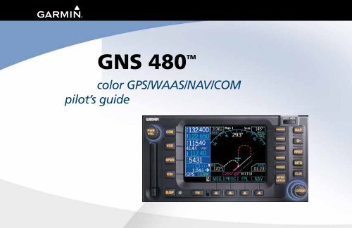
<strong>GNS</strong> <strong>480</strong> TM<br />
color GPS/WAAS/NAV/COM<br />
pilot’s guide<br />
DRAFT
© 2<strong>00</strong>6-2015 <strong>Garmin</strong> Ltd. or its subsidiaries<br />
<strong>Garmin</strong> International, Inc.<br />
<strong>Garmin</strong> AT<br />
12<strong>00</strong> East 151 st Street, Olathe, Kansas 66062, U.S.A. 2345 Turner Rd., SE Salem, OR 97302<br />
Tel. 913/397.82<strong>00</strong> Tel. 503/581.8101 or 8<strong>00</strong>/525.6726<br />
Fax 913/397.8282 Fax. 503/364.2138<br />
<strong>Garmin</strong> (Europe) Ltd.<br />
<strong>Garmin</strong> (Europe) Ltd., Liberty House, Bulls Copse Road, Hounsdown Business Park, Southhampton, SO40 9LR, U.K.<br />
Tel: +44 (0) 870 850 1243 (Europe) Fax: +44 (0) 238 052 4<strong>00</strong>4<br />
<strong>Garmin</strong> Singapore Pte Ltd<br />
46 East Coast Road, #05-06 Eastgate, Singapore 428766<br />
Tel. (65) 63<strong>480</strong>378<br />
Fax (65) 63<strong>480</strong>278<br />
All rights reserved. Except as expressly provided herein, no part of this manual may be reproduced, copied, transmitted, disseminated, downloaded or stored in any storage<br />
medium, for any purpose without the express prior written consent of <strong>Garmin</strong>. <strong>Garmin</strong> hereby grants permission to download a single copy of this manual onto a hard<br />
drive or other electronic storage medium to be viewed and to print one copy of this manual or of any <strong>rev</strong>ision hereto, provided that such electronic or printed copy of this<br />
manual must contain the complete text of this copyright notice and provided further that any unauthorized commercial distribution of this manual or any <strong>rev</strong>ision hereto is<br />
strictly prohibited.<br />
Information in this document is subject to change without notice. <strong>Garmin</strong> reserves the right to change or improve its products and to make changes in the content without<br />
obligation to notify any person or organization of such changes or improvements. Visit the <strong>Garmin</strong> Web site (www.garmin.com) for current updates and supplemental<br />
information concerning the use and operation of this and other <strong>Garmin</strong> products.<br />
<strong>Garmin</strong> ® , GPSMAP ® , AutoLocate ® , TracBack ® , Apollo, and MapSource ® are registered trademarks of <strong>Garmin</strong> Ltd. or its subsidiaries and may not be used without the<br />
express permission of <strong>Garmin</strong>.<br />
This part shall comply with <strong>Garmin</strong> Banned and Restricted Substances document, <strong>00</strong>1-<strong>00</strong>211-<strong>00</strong>.<br />
March 2015 <strong>Garmin</strong> AT Part Number 560-0984-01 Rev. G (<strong>Garmin</strong> P/N <strong>190</strong>-<strong><strong>00</strong>502</strong>-<strong>00</strong> Rev D) Printed in the USA
Introduction<br />
CAUTION: The Global Positioning System is operated by the United States government, which<br />
is solely responsible for its accuracy and maintenance. The system is subject to changes which<br />
could affect the accuracy and performance of all GPS equipment. Although the <strong>Garmin</strong> <strong>GNS</strong><br />
<strong>480</strong> is a precision electronic NAVigation AID (NAVAID), any NAVAID can be misused or misinterpreted<br />
and therefore become unsafe.<br />
CAUTION: Use the <strong>GNS</strong> <strong>480</strong> at your own risk. To reduce the risk of unsafe operation, carefully<br />
<strong>rev</strong>iew and understand all aspects of this Owner’s Manual and the Flight Manual Supplement,<br />
and thoroughly practice basic operation prior to actual use. When in actual use, carefully compare<br />
indications from the <strong>GNS</strong> <strong>480</strong> to all available navigation sources, including the information<br />
from other NAVAIDS, visual sightings, charts, etc. For safety, always resolve any discrepancies<br />
before continuing navigation.<br />
WARNING: The altitude calculated by the <strong>GNS</strong> <strong>480</strong> is geometric height above mean sea level<br />
and could vary significantly from altitude displayed by pressure altimeters in aircraft. GPS accuracy<br />
may be degraded by the U.S. Department of Defense-imposed Selective Availability (SA)<br />
programs.<br />
WARNING: The Jeppesen database incorporated in the <strong>GNS</strong> <strong>480</strong> must be updated regularly in<br />
order to ensure that its information is current. Updates are released every 28 days. A database<br />
information packet is included in your <strong>GNS</strong> <strong>480</strong> package. <strong>Pilots</strong> using an out-of-date database<br />
do so entirely at their own risk!<br />
CAUTION: GPS receivers operate by receiving and decoding very low power radio signals<br />
broadcast by satellites. It is possible that in some situations other radio equipment or<br />
electronic equipment used in close proximity to a GPS receiver may create electromagnetic<br />
interference (EMI) which may affect the ability of the GPS receiver to receive and decode the<br />
satellite signals. In such event, the interference may be reduced or eliminated by switching off<br />
the source of interference or moving the GPS receiver away from it.<br />
Cautions<br />
NOTE: This device complies with Part 15 of FCC<br />
limits for Class B digital devices. This equipment<br />
generates, uses, and can radiate radio frequency<br />
energy and, if not installed and used in accordance<br />
with the instructions, may cause harmful interference<br />
to radio communications. Furthermore, there<br />
is no guarantee that interference will not occur in a<br />
particular installation.<br />
If this equipment does cause harmful interference, the<br />
user is encouraged to try to correct the interference by<br />
relocating the equipment or connecting the equipment<br />
to a different circuit than the affected equipment.<br />
Consult an authorized dealer or other qualified avionics<br />
technician for additional help if these remedies<br />
do not correct the problem.<br />
Operation of this device is subject to the following<br />
conditions: (1) This device may not cause harmful<br />
interference, and (2) this device must accept any<br />
interference received, including interference that may<br />
cause undesired operation.<br />
i
Introduction<br />
Accessories and Packing List<br />
To obtain accessories for your <strong>GNS</strong> <strong>480</strong> please contact<br />
your <strong>Garmin</strong> dealer.<br />
Help us better support you by completing our on-line<br />
registration form today! Registration ensures that you<br />
will be notified of product updates and new products<br />
and provides lost or stolen unit tracking. Please, have<br />
the serial number of your <strong>GNS</strong> <strong>480</strong> handy, connect to<br />
our web site (www.garmin.com) and look for our<br />
Product Registration link on the home page.<br />
The <strong>GNS</strong> <strong>480</strong> display lens is coated with a special<br />
anti-reflective coating which is very sensitive to skin<br />
oils, waxes, and abrasive cleaners. It is very important<br />
to clean the lens using an eyeglass cleaner that<br />
is specified as safe for anti-reflective coatings (one<br />
suitable product is Wal-Mart Lens Cleaner) and a<br />
clean, lint-free cloth.<br />
CAUTION: The <strong>Garmin</strong> <strong>GNS</strong> <strong>480</strong> does not contain any user-serviceable parts. Repairs should<br />
only be made by an authorized <strong>Garmin</strong> service center. Unauthorized repairs or modifications<br />
could void your warranty and authority to operate this device under FCC Part 15 regulations.<br />
CAUTION: The electronic chart is an aid to navigation and is designed to facilitate the use of<br />
authorized government charts, not replace them. Only official government charts and notices<br />
to mariners contain all information needed for save navigation – and, as always, the user is<br />
responsible for their prudent use.<br />
Congratulations on choosing the world’s finest panel-mounted GPS IFR navigation/communication system<br />
certified for primary navigation! The <strong>GNS</strong> <strong>480</strong> represents <strong>Garmin</strong>’s continued commitment to providing you<br />
with the most advanced technology available today — in an accurate, easy-to-use design suitable for all your<br />
flying needs.<br />
Before installing and getting started with your new system, please ensure that your package includes the following<br />
items. If any parts are missing or are damaged, please contact your <strong>Garmin</strong> dealer.<br />
Standard Package:<br />
• • <strong>GNS</strong> <strong>480</strong> Unit and NavData Card<br />
• • Mounting Tube and Installation Kit<br />
• • Pilot’s <strong>Guide</strong> and Quick Reference <strong>Guide</strong><br />
• • <strong>GNS</strong> <strong>480</strong> Interactive Training CD<br />
• • Database Subscription Packet<br />
• • Warranty Registration Card<br />
• • * GPS Antenna kit is available as a separate option selected at the time of order<br />
Your <strong>Garmin</strong> dealer will perform the installation and configuration of your new <strong>GNS</strong> <strong>480</strong>. After installation,<br />
the NavData card will already be installed into the unit. The <strong>GNS</strong> <strong>480</strong> will be secured in the mounting tube<br />
with the proper wiring connections. Have your dealer answer any questions you may have about the installation<br />
— such as location of antennas or any connections to other equipment in the panel.<br />
ii
Preface<br />
Thank you for choosing the <strong>Garmin</strong> <strong>GNS</strong> <strong>480</strong>. The <strong>GNS</strong> <strong>480</strong> utilizes the proven performance of <strong>Garmin</strong> GPS<br />
and full-featured mapping to create an unsurpassed aviation navigation system. Please take a moment now to<br />
compare the contents of this package with the packing list on the outside of the box. If any pieces are missing,<br />
please contact your <strong>Garmin</strong> dealer immediately.<br />
About This Manual<br />
To get the most out of your new navigation system, take time to read this manual and learn the operating<br />
procedures for your unit in detail. This manual is organized into the following chapters.<br />
The Introduction chapter contains the Table of Contents.<br />
The Getting Started chapter provides information such as an overview of unit features and how to turn the<br />
unit on and adjust the backlight. The <strong>GNS</strong> <strong>480</strong> also contains a simulator mode to help you get acquainted<br />
with its functions and features.<br />
The Basic Operation chapter provides you with information about basic features such as using the Moving<br />
Map, Com and Nav radios, navigating a route, and using waypoints. There are also step-by-step directions to<br />
assist you in these operations.<br />
The Appendix contains information such as specifications, optional accessories, and maintenance information.<br />
You can also find warranty, safety, and FCC information in the Appendix.<br />
An Index is provided at the end of the manual for reference. Simply look up the topic you wish to learn about<br />
and read the page or pages listed.<br />
Introduction<br />
Welcome<br />
The <strong>GNS</strong> <strong>480</strong> uses GPS technology in order to find your precise<br />
location. GPS stands for Global Positioning System, a group<br />
of 24 satellites, circling the earth twice a day at an altitude of<br />
about 12,<strong>00</strong>0 miles. The satellites transmit very low power<br />
radio signals containing position and time information, allowing<br />
anyone with a GPS receiver to determine their location on<br />
the Earth within 1<strong>00</strong> meters or better. For more detailed<br />
information regarding GPS, <strong>Garmin</strong> has prepared a booklet<br />
titled “GPS <strong>Guide</strong> for Beginners” available from our Web site at<br />
www.garmin.com.<br />
iii
Introduction<br />
iv<br />
Table of Contents<br />
Introduction............................................ i<br />
Cautions..................................................................i<br />
Accessories and Packing List.......................... ii<br />
Welcome................................................................iii<br />
Preface................................................................ iii<br />
About This Manual.............................................. iii<br />
Getting Started..................................... 1<br />
Controls............................................................... 2<br />
Datacard............................................................... 4<br />
Display................................................................. 5<br />
Using the Moving Map......................................... 6<br />
Annunciations.............................................. 11<br />
Starting Up......................................................... 13<br />
Set Fuel Full and Reserve................................... 13<br />
Self-Tests............................................................ 13<br />
Database Check.................................................. 13<br />
View Checklists.................................................. 14<br />
View Messages.................................................... 14<br />
Set Com and Nav Frequencies............................ 14<br />
Using the Remote Transponder........................... 15<br />
Change the Transponder (Squawk Code) - Two<br />
Methods................................................. 15<br />
Transponder Options................................... 15<br />
Nav Terms Diagram...................................... 16<br />
Flight Plan Terms Diagram........................... 16<br />
Create a New Flight Plan (Quick Method).......... 17<br />
Select a Direct-To a Waypoint in Your Flightplan.17<br />
Select a Direct To Waypoint Not in Your Flightplan<br />
.................................................................... 17<br />
Find a Nearest Waypoint.................................... 18<br />
Find a Nearest Waypoint Frequency................... 18<br />
Inserting Terminal Procedures and Approaches.. 19<br />
Perform a RAIM Prediction................................. 19<br />
Moving Map Mode (MAP)....................................20<br />
True North......................................................... 20<br />
Moving Map Mode Menu Items.......................... 21<br />
<strong>GNS</strong> <strong>480</strong> Map Mode Nav Data Options.............. 22<br />
Basic Operation................................... 24<br />
Nav/HSI Display (NAV)..........................................31<br />
Panning (PAN).......................................................33<br />
Range................................................................. 33<br />
Create a New User waypoint.............................. 33<br />
Direct-To...............................................................34<br />
ActFP................................................................. 34<br />
DB .................................................................... 34<br />
Direct................................................................. 34<br />
Inserting a Hold at a Waypoint in the Active Flight<br />
Plan.............................................................. 35<br />
Destination (Dest).............................................. 35<br />
Course-To (CrsTo).............................................. 36<br />
Course From (CrsFr).......................................... 36<br />
OBS.................................................................... 37<br />
OBS to a Waypoint in Your Flight Plan............... 37<br />
OBS to a Waypoint Not in Your Flight Plan........ 38<br />
FlyLeg................................................................ 38<br />
Nearest (NRST) Search..........................................39<br />
Search Around a Reference Point (SRCH)........... 39<br />
Nearest Frequency.............................................. 39<br />
FSS and ARTCC Frequencies.............................. 40<br />
Info on Nearest Waypoint................................... 40<br />
Fly Direct-To a Nearest Waypoint....................... 40<br />
Using the NRST Function to Change Your Destination<br />
to a Nearest Airport............................... 41<br />
Search for All Nearest Airports/Helipads............. 41<br />
Information on Waypoints (INFO).........................42<br />
Airport Information............................................ 42<br />
Airport Frequency Information.................... 43<br />
VOR Information............................................... 44<br />
NDB Information............................................... 44<br />
Airway Intersection Information......................... 44<br />
RAIM Prediction................................................. 45<br />
Com Radio (COM).................................................46<br />
Squelch (SQ)...................................................... 46<br />
Tx/Rx................................................................. 46<br />
Monitor (MON)................................................. 46<br />
Recall (RCL)....................................................... 46<br />
Recent................................................................ 46<br />
User................................................................... 47<br />
Emergency......................................................... 47<br />
Flip/Flop............................................................ 47<br />
Signal................................................................. 47<br />
Weather.............................................................. 47<br />
Audio................................................................. 48<br />
Save Channel..................................................... 48<br />
Nav Radio (VOR)...................................................49<br />
DME Distance.................................................... 49<br />
ID .................................................................... 49
Introduction<br />
Monitor (MON)................................................. 49<br />
Recall (RCL)....................................................... 50<br />
Flip/Flop............................................................ 50<br />
ID/To/Fr............................................................. 50<br />
Back Course....................................................... 50<br />
Audio................................................................. 50<br />
User................................................................... 50<br />
Save Channel..................................................... 50<br />
Test Log.............................................................. 51<br />
Transponder Control (XPDR).................................52<br />
Ident.................................................................. 52<br />
Standby.............................................................. 52<br />
ON .................................................................... 52<br />
ALT.................................................................... 52<br />
Transponder Line Selection Keys........................ 52<br />
Emergency................................................... 52<br />
VFR.............................................................. 53<br />
TrgrSpd........................................................ 53<br />
Auto............................................................. 53<br />
Flight ID...................................................... 53<br />
Ground........................................................ 54<br />
Manually Select a Squawk Code......................... 54<br />
Flight Planning (FPL).............................................55<br />
Active Flight Plan......................................... 55<br />
Modified Flight Plan..................................... 55<br />
Remote Flight Plan....................................... 55<br />
Library Flight Plan....................................... 56<br />
Flight Plan Functions......................................... 56<br />
View............................................................. 56<br />
Back............................................................. 56<br />
Edit.............................................................. 56<br />
Expand (XPND) .......................................... 56<br />
Cross Link (X-Link) .................................... 57<br />
Remote Flight Plans...................................... 57<br />
Reverse (Rvrse) ............................................ 57<br />
Save............................................................. 57<br />
Edit.............................................................. 58<br />
Execute (Exec) ............................................ 58<br />
Comment (Cmnt) ........................................ 58<br />
Copy ........................................................... 58<br />
Discontinuity..................................................... 59<br />
Pilot Nav Legs.................................................... 59<br />
Searching for Waypoints to Insert into a Flight Plan<br />
.................................................................... 60<br />
Activate a Flight Plan.......................................... 61<br />
Delete the Active Flight Plan.............................. 61<br />
Edit a Flight Plan................................................ 61<br />
Changing Origin, Destination, & Alternate<br />
Waypoints.............................................. 61<br />
Inserting a Waypoint or Airway in Your Flight<br />
Plan........................................................ 61<br />
Deleting a Waypoint or Airway in Your Flight<br />
Plan........................................................ 62<br />
Steps for Setting Up a Simple Flight Plan........... 62<br />
Steps for Setting Up a Flight Plan Using Terminal<br />
Procedures and Airways............................... 62<br />
A. Set Origin, Destination, and Alternate<br />
Waypoints ............................................. 63<br />
B. Add a Standard Instrument Departure (SID)<br />
Procedure............................................... 63<br />
C. Insert En Route Flight Plan Airways and/or<br />
Waypoints.............................................. 64<br />
D. Modifying a Flight Plan While In Flight... 64<br />
E. Add Arrival Procedures (STARS).............. 65<br />
F. Add Approach Procedures........................ 65<br />
LEG TYPES ....................................................... 66<br />
Turn Short Path Calculation......................... 66<br />
Procedures............................................................75<br />
Selecting Procedures........................................... 75<br />
Activating an Approach...................................... 75<br />
Steps for approach operations...................... 76<br />
Basic Approach Operations Examples................. 76<br />
Approaches with Procedure Turns...................... 77<br />
Flying the Procedure Turn.................................. 78<br />
Flying the Missed Approach............................... 80<br />
Flying an Approach with a Hold......................... 81<br />
Flying a DME Arc Approach............................... 84<br />
Vectors To Final.................................................. 87<br />
Flying a Vectored Approach................................ 88<br />
ILS Approaches.................................................. 90<br />
Selecting an ILS Approach............................ 91<br />
Flying the ILS Approach............................... 92<br />
Selecting an LPV Approach................................ 96<br />
Flying the LPV Approach............................. 96<br />
Flying the LP Approach...................................... 97<br />
RNAV Approach Procedures............................... 99<br />
Timers (TMR)......................................................103<br />
Timer 1 and Timer 2........................................ 103<br />
Trip Time and Distance.................................... 103<br />
Flight Time and Distance.................................. 104<br />
Trigger Speed................................................... 104<br />
Checklist (CHK)...................................................105<br />
v
Introduction<br />
Creating a New or Editing an Existing Checklist.105<br />
Using Your Checklist........................................ 105<br />
Move a Checklist.............................................. 106<br />
User Waypoints (USER).......................................109<br />
Creating or Editing a User Waypoint................ 109<br />
Searching for a User Waypoint......................... 109<br />
System Mode (SYS).............................................110<br />
GPS Status........................................................ 110<br />
Software Versions............................................. 110<br />
Configuration................................................... 111<br />
Barometric Correction................................ 111<br />
Barometric Pressure Units.......................... 111<br />
Magnetic Variation Selection....................... 112<br />
Magnetic Variation Degree Value................ 112<br />
CDI Scale................................................... 112<br />
ILS CDI...................................................... 113<br />
Distance Units............................................ 113<br />
Altitude Units............................................. 113<br />
Fuel Type................................................... 114<br />
Fuel Units.................................................. 114<br />
Fuel Full Amount....................................... 114<br />
Fuel Low Message...................................... 115<br />
Display Brightness Selection....................... 115<br />
Minimum Brightness Value......................... 116<br />
Message Tone............................................. 116<br />
Airspace Alerts........................................... 116<br />
Owner Information.................................... 117<br />
Aircraft Icon............................................... 117<br />
VFR Squawk.............................................. 117<br />
Enable SBAS Providers .............................. 118<br />
Parallel Track (PTK).............................................119<br />
Simulator Mode..................................................121<br />
Automatic Track (ATK)..................................... 121<br />
Manual Track................................................... 121<br />
Present Position (PPOS)................................... 122<br />
Airspeed........................................................... 122<br />
Messages (MSG).................................................123<br />
Text Messages................................................... 123<br />
Audio Messages ............................................... 128<br />
Setting Message Audio Level...................... 128<br />
Traffic (TFC).........................................................129<br />
Traffic Display Range Ring................................ 129<br />
Traffic Symbols................................................. 129<br />
Traffic Pop-Up.................................................. 130<br />
No-Bearing Traffic Advisories (Skywatch Only).130<br />
Vertical Display Modes..................................... 131<br />
Operate/Standby.............................................. 131<br />
Test.................................................................. 131<br />
Traffic in Map Mode......................................... 132<br />
Traffic Annunciations....................................... 132<br />
Specifications.....................................................133<br />
Physical Specifications...................................... 133<br />
Power............................................................... 133<br />
Environmental.................................................. 133<br />
GPS Performance............................................. 133<br />
VHF Comm Performance................................. 133<br />
VOR Performance............................................. 133<br />
Localizer Performance...................................... 133<br />
Glideslope Performance.................................... 133<br />
Care Information ...............................................134<br />
Cleaning the Unit............................................. 134<br />
Battery Replacement......................................... 134<br />
Display Backlight............................................. 134<br />
<strong>Garmin</strong> Data Cards.............................................135<br />
Installing and Removing Data Cards................. 135<br />
Appendix........................................... 135<br />
Glossary..............................................................137<br />
WAAS..................................................................144<br />
Safety Information.............................................144<br />
What is WAAS?................................................ 144<br />
Safety Information............................................ 144<br />
Compliance, License, and Warranty Information.145<br />
FCC Compliance.............................................. 145<br />
Canadian RF Exposure and Compliance........... 146<br />
Software License Agreement............................. 147<br />
Product Registration and Support..................... 147<br />
Limited Warranty............................................. 148<br />
Index...................................................................149<br />
vi
This guide describes the operation of the <strong>GNS</strong> <strong>480</strong> (CNX80) Color GPS/WAAS NavCom. The <strong>GNS</strong> <strong>480</strong><br />
(CNX80) provides a new, higher level of accuracy, integrity, integration, flight planning capability, and convenience<br />
for the pilot. The <strong>GNS</strong> <strong>480</strong> (CNX80) combines a large number of easily accessible controls to use the<br />
high-resolution color multi-function display, Nav and Com transceivers, GPS/WAAS navigator, and transponder<br />
controller all in a single unit. The <strong>GNS</strong> <strong>480</strong> (CNX80) with the GPS/WAAS navigator is certified for use as<br />
primary navigation equipment for both VFR and IFR operations.<br />
This Pilot’s <strong>Guide</strong> covers the details, so you can get the most out of your <strong>GNS</strong> <strong>480</strong> (CNX80), quickly. For more<br />
details and examples, refer to the <strong>GNS</strong> <strong>480</strong> (CNX80) Computer-Based Training (CBT) compact disc and inflight<br />
demo DVD which are provided for your convenience. These documents and the Quick Reference <strong>Guide</strong>,<br />
when used with the simulator for practice, will prepare you to get the most out your equipment.<br />
Getting Started<br />
1
2<br />
Getting Started<br />
Push the PWR/VOL knob in to turn the unit on. Press<br />
the COM, VOR, XPDR keys to activate that mode. Press<br />
CDI to select the CDI source. Press SUSP to suspend<br />
waypoint sequencing.<br />
Press the “smart” key below the function label to activate<br />
the named function. Pressing FN scrolls available<br />
functions.<br />
Controls<br />
Power/Volume<br />
The knob at the top left corner of the <strong>GNS</strong> <strong>480</strong> controls power on/off and the radio volume. Push the<br />
PWR/VOL knob in to turn power on. Pull the knob out to turn power off. When the power knob is<br />
pulled out, a time-out message and counter will appear for five seconds. Turning the knob will control<br />
the volume of the COM radio, unless the NAV radio is active then the NAV volume is controlled.<br />
A white border surrounding the Com, VOR, and XPDR information will flash and the values you can<br />
change will be highlighted when each mode is activated.<br />
FN and Function Smart Keys<br />
Press the FN key to page through the available group of Functions that appear at the bottom of the<br />
display. The “Smart” function keys located below each label will activate that function.<br />
COM<br />
Select Com radio mode. Press COM. The function and menu item smart keys access more features.<br />
VOR<br />
Select Nav radio mode. Press VOR. The function and menu item smart keys access more features.<br />
XPDR<br />
Select the External Transponder mode, if installed. Press XPDR. The function and menu item smart<br />
keys access more features.<br />
CDI<br />
Toggles the main CDI output between GPS and internal VOR/LOC radio sources.<br />
SUSP<br />
Manually suspends or resumes flight plan waypoint sequencing. When waypoint sequencing is<br />
suspended, the SUSP annunciator will be displayed in the bottom left corner of the display. The <strong>GNS</strong><br />
<strong>480</strong> will auto-suspend when required for certain procedures, such as Vectors-To-Final (VTF) mode. In<br />
VTF mode, if you are within 45° of the inbound course and you are on the TO side, the “SUSP” mode<br />
will turn off and return to normal sequencing. See page 99 for more details.
MAP<br />
Selects the moving Map mode. Press MAP twice to view Map page 1. Turn the Large knob to view all<br />
four MAP pages. The function and menu item smart keys access more features.<br />
Getting Started<br />
Direct-To<br />
Selects the Direct-To page. Menu options allow setting up Direct-To (D->), setting a customized<br />
holding pattern around a waypoint (Hold), Course To (CrsTo) a waypoint, Course From (CrsFr) a<br />
waypoint, OBS mode uses input from your CDI Course Selector, and activating a given leg of your<br />
active flight plan (FlyLeg). The function and menu item smart keys access more features.<br />
NRST<br />
Activates Nearest Search. You can search through the closest 20 of airports, NDBs, VORs, intersections,<br />
airspaces, user-created waypoints, Flight Service Station (FSS) with frequency data, and Air<br />
Route Traffic Control Center (ARTCC) with frequency data. The function and menu item smart keys<br />
access more features.<br />
INFO<br />
Activates Info mode for the highlighted waypoint or the active flight plan (ActFP) waypoint. Information<br />
about the selected waypoint such as location, name, a map, frequencies, and more depending on<br />
the waypoint type is provided. When frequencies are provided and highlighted, pressing the to go<br />
direct-to a selection. Press NRST to search for the<br />
Nearest . Press INFO to view information about a<br />
selected waypoint. Press CLR to clear information or<br />
ignore a choice.<br />
CLR<br />
Clears text when editing or deletes the highlighted item.<br />
3
Getting Started<br />
MENU/ENTER and Menu Item Keys<br />
When editing information, or a response is required, pressing the Menu/Enter key accepts the value<br />
or confirms the response. In COM, VOR, XPDR, and MAP modes, pressing this key will bring up a<br />
list of menu items on the right side of the display allowing the pilot to select. The menu items are<br />
then selected by pressing the key to the right of it. Pressing the Menu/Enter key while the menu<br />
items are shown will remove them from view.<br />
Large/Small Knobs<br />
You can move the cursor or highlight information by turning the Large knob. Turn the Small knob<br />
to change information.<br />
CRSR<br />
Press the Small knob in to activate the cursor (CRSR). The area on the display that you can now edit<br />
will be highlighted. Now you can change information with the Small knob and move the cursor<br />
to the next area to edit with the Large knob. If you are in Map mode, pressing the CRSR activates<br />
PAN mode. In Transponder mode, it allows editing squawk codes. In Direct-To and Flight Plan (FPL)<br />
modes, activating the CRSR control will help narrow a waypoint search.<br />
Datacard<br />
The Map database and other information is stored on a data card. The use of a data card allows you to easily<br />
update information.<br />
NOTE: Only change the data card when the power is turned off or you may damage your unit.<br />
Handle your data card carefully. Do not touch the connector edge of the data card. To eject the card, press the<br />
data card ejector. Gently pull the card straight out of the slot. Insert a data card by pushing the card straight into<br />
the slot. When fully inserted, the data card and eject button will be flush and slightly recessed into the bezel.<br />
When contacting your dealer or the <strong>Garmin</strong> customer service staff, eject the data card and write down the<br />
information shown on the label.<br />
NOTE: Never insert or eject the data card with the power on.<br />
4
Display<br />
The <strong>GNS</strong> <strong>480</strong> uses a high-resolution color display to provide information about the different functions. Information<br />
and “smart keys” unique for each mode of operation are displayed. Sample displays with a description<br />
of common elements are shown below.<br />
Getting Started<br />
When you press the COM, VOR, or XPDR keys on the left side of the<br />
display, the window for that function will be outlined and the information<br />
active for editing will be highlighted.<br />
The labels for the bottom row of Function smart keys will change for each<br />
function selected. Press Menu/Enter to display Menu Item smart keys. The<br />
Menu Item smart keys will adjust to the options for each function.<br />
5
Getting Started<br />
Using the Moving Map<br />
The Map mode provides a moving map for a graphic display of your flight including the surrounding area,<br />
as well as navigation information to aid your situational awareness. You can customize each of the four Map<br />
pages for the Map range and the information displayed, such as Airports, VORs, NDBs, Intersections, User<br />
Waypoints, Airspace, Traffic from TIS or Skywatch, Hi and Lo Airways, Flight Plan course line, or Nav information<br />
items. When decluttering is selected, the map is automatically decluttered to remove map detail for<br />
clarity as you increase the map range.<br />
1. Press MAP to reach Map mode. Radio, Nav, Transponder, CDI, Annunciator, or pilot-customized<br />
information is shown on the left side of the display and the map display is shown on the right side.<br />
2. There are four Map pages that you select by turning the Large knob.<br />
3. Turn the Small knob to change the Map range. Map pages 2-4 allow you to customize the Nav display<br />
items on the left side of the display and map display detail.<br />
4. Press Menu/Enter to view the Menu items for the choices to customize your display.<br />
5. Press the key next to the Menu item to change the item values.<br />
6. Press the More key to go to the next page of Menu items.<br />
6
Getting Started<br />
The following symbols are used on the map display to depict active legs of flight, waypoint types, and your aircraft.<br />
Turn Left for next flight<br />
plan leg<br />
Turn Right for next<br />
flight plan leg<br />
Airport<br />
VOR<br />
Ownship - Single<br />
Ownship - Twin<br />
No course change VORTAC Ownship - Jet<br />
Left Procedure Turn<br />
Outbound<br />
VOR-DME Ownship -<br />
Helicopter<br />
Arc to the Left NDB Flight Plan<br />
Waypoint<br />
Arc to the Right User Waypoint Intersection<br />
Left Procedure Turn<br />
Inbound<br />
Entering Procedure Turn<br />
Right<br />
Right Hand Holding<br />
Pattern Outbound<br />
Entering Procedure<br />
Turn Left<br />
Direct-To<br />
Right Hand Holding<br />
Pattern Inbound<br />
Left Hand Holding<br />
Pattern Inbound<br />
Left Hand Holding<br />
Pattern Outbound<br />
7
8<br />
Getting Started
Getting Started<br />
9
10<br />
Getting Started
Getting Started<br />
Annunciations<br />
The following annunciations appear on the appropriate displays to provide status or information. All annunciations<br />
are available on the moving map display. Annunciations may be output to external annunciators.<br />
Annunciation<br />
GPS<br />
VOR/ILS/LOC<br />
ENR<br />
TERM<br />
APPR<br />
LOI<br />
BC<br />
DR<br />
PTK<br />
SUSP<br />
Description<br />
Indicates GPS is being used as the navigation source. Appears in lower left corner of the display.<br />
Indicates VOR/ILS/LOC is being used as the navigation source. Appears in lower left<br />
corner of the display.<br />
Appears to the right of the “GPS” annunciator when in En Route mode. When > 30 nm<br />
from departure or destination and not on departure or arrival procedure. CDI resolution<br />
is ± 2 nm.<br />
Appears to the right of the “GPS” annunciator when performing approach navigation<br />
within 30 nm of departure or arrival airport. CDI resolution is ± 1 nm.<br />
Appears to the right of the “GPS” annunciator when GPS approach is active, and on Final<br />
Approach course (i.e. VTF or FAF, MAP, or the first Missed Approach waypoint is active. CDI<br />
resolution is variable for all approaches and becomes more sensitive as you near the runway.<br />
“LOI” (Loss of Integrity) appears on the left side of the map display when WAAS/GPS is<br />
unable to calculate the integrity of the position or calculated integrity is insufficient to<br />
support the current phase of flight.<br />
The Back Course annunciation appears to the right of “LOC” when the Back Course<br />
Localizer mode is enabled.<br />
The Dead Reckoning annunciator appears on the left side of the map display when GPS<br />
position is unavailable and the <strong>GNS</strong> <strong>480</strong> is in Dead Reckoning mode. Dead Reckoning<br />
mode will continue until GPS position is restored or the first Pilot Nav leg is reached.<br />
The Parallel Track annunciator appears in the lower left corner of the display when parallel<br />
track is active.<br />
Suspend annunciation appears in the lower left corner of the display when automatic<br />
sequencing of waypoints in the active flight plan is suspended.<br />
11
Getting Started<br />
M<br />
VTF<br />
ALT<br />
CDI Window<br />
CDI Window:<br />
Rwy Dist/Brg<br />
CDI Window:<br />
FLAGGED<br />
CDI Window:<br />
HDG xx°<br />
CDI Window:<br />
PILOT NAV<br />
TFC, TFC Fail, TFC STBY,<br />
TFC Test, TFC N/A<br />
LPV, LP, Lnav/Vnav, Lnav<br />
LP +V<br />
Lnav+V<br />
Message annunciation appears in the lower left corner of the display when a message is<br />
available for viewing. A blinking “M” indicates a new message.<br />
Vector To Final annunciation appears in the lower left corner of the display when “Vector<br />
To Final” approach mode is active, which may be activated manually or automatically.<br />
Appears for Lnav/Vnav, Lnav+V, or LPV approaches when the aircraft’s estimated height<br />
is lower than the Final Approach waypoint height by more than the current VPL plus 50<br />
meters.<br />
Shows course deviation, heading, or PILOT NAV.<br />
Shows distance To runway and a bearing direction indicator for LPV, LNAV, Lnav+V, and<br />
Lnav/Vnav approaches.<br />
No active guidance is available for the selected Nav source (VHF Nav radio or GPS receiver).<br />
For GPS, the usual causes are Loss of GPS position, Loss Of Integrity, or inadequate<br />
GPS HPL or VPL on the Final Approach leg.<br />
Displayed when a PILOT NAV Heading Leg is the active flight plan leg. The current heading<br />
is shown. If heading information is not available, the field is dashed.<br />
Guidance is not provided on this leg by the <strong>GNS</strong> <strong>480</strong>. Use other flight instruments to fly<br />
this leg.<br />
Status of the external traffic source.<br />
LPV is for GPS precision approaches. Amber indicates the current vertical (VPL) or<br />
horizontal protection level (HPL) exceeds the alarm limit. Green indicates the VPL and<br />
HPL are acceptable for LPV or Lnav/Vnav approaches (WAAS environment). LP indicates<br />
Localizer Performance with no vertical guidance. LPV indicates Localizer Performance<br />
with vertical guidance. Lnav/Vnav indicates an Lnav approach with vertical guidance.<br />
Lnav indicates an Lnav-only approach with no vertical guidance.<br />
LP +V indicates Localizer Performance with advisory vertical guidance. Fly LP minimums<br />
down to the MDA and missed approach location. This annunciation is available in SW<br />
Ver 2.4, or later.<br />
GPS approach using published LNAV minima. Advisory vertical guidance is provided.<br />
12
Starting Up<br />
The <strong>GNS</strong> <strong>480</strong> performs internal checks and shows the status of the tests during start up. The startup screen,<br />
owner name (if entered), testing, position, and database information shows on the screen for several seconds<br />
and then shows the first Map page. It is not generally necessary to enter a GPS seed position unless the unit<br />
has either been moved several hundred miles or been unused for six months or so with the power off. A seed<br />
position should have been entered the first time the unit was turned on during installation.<br />
Power Up<br />
1. Push the PWR/VOL knob in to turn on power.<br />
2. When the position display appears, you can press CHG to manually enter your present position or just<br />
wait a few seconds for the <strong>GNS</strong> <strong>480</strong> to establish your position.<br />
3. The <strong>GNS</strong> <strong>480</strong> performs a number of tests at startup to ensure proper operation. You may press SKIP to<br />
bypass the startup tests, however, completing these tests is required for IFR flight. Any failures will be<br />
noted by a message.<br />
Getting Started<br />
Start-Up Display<br />
Set Fuel Full and Reserve<br />
If a Fuel/Air Data Computer is installed, Fuel Full and Fuel Reserve amounts are entered manually in the Configuration<br />
page of System mode and are reflected in the start-up screens. On start-up, you will be prompted for<br />
the Total Fuel on Board.<br />
Press the Menu/Enter key to accept the displayed amount of fuel or change the displayed amount with the<br />
Small knob and then press the Menu/Enter key.<br />
Self-Tests<br />
The <strong>GNS</strong> <strong>480</strong> performs internal checks and shows the status of the tests during start up. After these internal<br />
checks, the <strong>GNS</strong> <strong>480</strong> is ready to navigate.<br />
Database Check<br />
The <strong>GNS</strong> <strong>480</strong> verifies the integrity and expiration date of the database. Up to two database cycles are supported.<br />
The <strong>GNS</strong> <strong>480</strong> will load the appropriate current database cycle and also let you know if a database is<br />
not current (dates invalid).<br />
Database Verification<br />
13
Getting Started<br />
The database information can be checked after start-up in the SW Version page of the System function. Press<br />
the Menu/Enter key to continue after you have verified the dates. Valid databases are in green. The database<br />
being used has an asterisk (*) next to it, if there are two databases. Expired databases are amber.<br />
View Checklists<br />
Use a checklist to <strong>rev</strong>iew preparation for flight.<br />
1. Press FN and then the CHK function smart key.<br />
2. Turn the Large knob to select the desired list and press Menu/Enter.<br />
3. Press CHCK or Menu/Enter as you check each item on the list. The next item in the list will then be<br />
highlighted. Checking the last item will take you back to the main Checklist page.<br />
View Messages<br />
You can <strong>rev</strong>iew system messages by pressing the MSG function smart key. Turn the Large knob to switch<br />
between New and Old messages. Turn the Small knob to scroll through the available messages. The Message<br />
annunciator (M) will flash until all unread messages have been read. While old messages exist and there are<br />
no new messages, the Message annunciator will remain solid. The Message annunciator will not appear when<br />
there are no messages.<br />
Set Com and Nav Frequencies<br />
You can set the Com and Nav frequencies manually<br />
1. Press Com for VHF Com frequencies or press VOR for VOR/LOC/ILS frequencies.<br />
2. Turn the Large knob to select MHz and turn the Small knob for kHz of the stand-by frequency.<br />
3. Press the key to flip-flop the active and stand-by frequencies.<br />
4. Press MON to toggle monitoring of the stand-by frequency.<br />
5. Turn the PWR/VOL knob to adjust the audio level.<br />
14
Using the Remote Transponder<br />
The Transponder Control Mode will allow you to control a compatible remotely mounted transponder from<br />
the <strong>GNS</strong> <strong>480</strong> front panel. Press XPDR to activate Transponder mode.<br />
Change the Transponder (Squawk Code) - Two Methods<br />
1. Turn the Large knob to highlight the Squawk Code.<br />
2. Turn the Small knob to select a number and then turn the Large knob to move to the next character.<br />
3. The Ident is automatically saved after selecting the fourth character.<br />
OR<br />
1. Press the Cursor (CRSR) knob in.<br />
2. Press the function or menu item smart keys next to the numbers 0-9 shown on the bottom and right<br />
side of the display in the order desired.<br />
3. The Ident is automatically saved after selecting the fourth character.<br />
Transponder Options<br />
Press Menu/Enter to view options. Controls and features may vary depending on the transponder.<br />
• Press the Emrgncy menu item key and then Menu/Enter to insert the 77<strong>00</strong> squawk code.<br />
• Press the VFR menu item key to insert the 12<strong>00</strong> squawk code.<br />
• Press the TrgrSpd menu item key to select the speed that will “trigger” the automatic activation of the<br />
transponder (SL70 only) when in Auto mode.<br />
1. Turn the Large and Small knobs to select the trigger speed.<br />
2. Press Menu/Enter to save the trigger speed.<br />
• Press Auto to toggle the Auto Activate mode. The transponder (SL70 only) automatically goes from<br />
standby to active when accelerating past the Trigger Speed and goes from active to standby when<br />
decelerating below the Trigger Speed.<br />
• Press IDNT to activate Ident mode.<br />
• Press STBY to place the transponder in Standby.<br />
• Press ON to enable Mode A operation (sends a squawk code).<br />
• Press ALT to enable Mode C/S operation (sends a squawk code and altitude data).<br />
Getting Started<br />
Changing the transponder squawk code<br />
Transponder details<br />
15
Getting Started<br />
Nav Terms Diagram<br />
Flight Plan Terms Diagram<br />
16
Create a New Flight Plan (Quick Method)<br />
The Flight Planning function lets you set up and store flight plans where you can name the flight plan, insert a<br />
series of waypoints, and then add comments. The Active flight plan is the flight plan that the <strong>GNS</strong> <strong>480</strong> is currently<br />
using for navigation guidance. The Modified flight plan is a temporary copy of the active flight plan that you can<br />
edit prior to executing or saving the changes. The active plan won’t be affected until you execute the modified plan.<br />
A remote flight plan is one that has been received from another connected <strong>GNS</strong> <strong>480</strong>, but while the units are not<br />
setup for Cross-Link (X-Link) mode. The Library flight plans are stored flight plans for future use. This is a quick<br />
start overview of flight planning. See the Flight Planning section for more detail.<br />
1. Press FN and then the FPL function smart key.<br />
2. Press New.<br />
3. Use the Large and Small knobs to select the Origin waypoint and then press Menu/Enter.<br />
4. Use the Large and Small knobs to select the Destination waypoint and then press Menu/Enter. This<br />
allows you to select the appropriate terminal procedures from the database. The active flight plan is<br />
deleted and is replaced with the new Direct-To flight plan.<br />
5. Highlight the departure waypoint and insert a waypoint or airway. Continue inserting waypoints or<br />
airways until the route is complete.<br />
6. The flight plan is automatically saved into the Library and named by the Origin and Destination<br />
waypoints.<br />
7. Press the Exec key to execute the flight plan and make it the active flight plan.<br />
Select a Direct-To a Waypoint in Your Flightplan<br />
1. Press the D-> key.<br />
2. Turn the Large knob to highlight a waypoint.<br />
3. Press the Direct menu selection key.<br />
Select a Direct To Waypoint Not in Your Flightplan<br />
1. Press the D-> key and then the DB function smart key.<br />
2. Select a waypoint using the Small knob to select a character and the Large knob to move to another<br />
character.<br />
3. Press the Direct menu item key.<br />
Getting Started<br />
Flying Direct-To a new destination<br />
(Direct-To - DEST)<br />
17
Getting Started<br />
Nearest waypoint search - Airport<br />
(TWR/CTAF - Frequencies)<br />
Nearest airport frequencies<br />
Find a Nearest Waypoint<br />
The Nearest (NRST) Waypoint Search function allows you to search for the 20 waypoints nearest to your present<br />
position in each of eight waypoints types: Airport, VOR, NDB, INT, User, FSS (Flight Service Station), Airspace,<br />
and Air Route Traffic Control Center (ARTCC). You can also set Limits to select a range of airport types<br />
to show up for the Nearest Airport type. You can then look up information about a waypoint or fly direct to it<br />
1. Press NRST. The default waypoint type is Airport.<br />
2. Press the menu item key for the desired waypoint type. Press the More menu item key to display more<br />
types.<br />
3. Turn the Large knob to scroll through the list.<br />
4. Press the Standby ( to fly direct to the highlighted waypoint or press INFO to display information about that<br />
waypoint.<br />
6. Press the RAIM function key to perform a RAIM prediction.<br />
Find a Nearest Waypoint Frequency<br />
1. Press NRST and then press the menu item key for the desired waypoint type. Turn the Large knob to<br />
highlight the desired waypoint.<br />
2. If the desired frequency is shown in the Nearest list, press the Standby (
Inserting Terminal Procedures and Approaches<br />
After creating your flight plan, you can select an approach, departure, or arrival procedure so the <strong>GNS</strong> <strong>480</strong> can<br />
guide you through the flight plan. You may also make adjustments in Flight Edit mode.<br />
1. Press the PROC function smart key for Procedure Mode. The Origin and Destination waypoint of your<br />
active flight plan are shown.<br />
2. Press the Depart menu item smart key to select the Departure procedure. If available, select the<br />
departure runway (with the Small knob or the menu item keys).<br />
3. Turn the Large knob to highlight the transition and turn the Small knob to make the selection. Press<br />
Menu/Enter to accept the selections.<br />
4. Press the BACK function smart key to return to the Procedures mode. Depending on the procedure for<br />
your destination, press the Destination Arrival or Appch menu item smart key.<br />
5. Choose the transition and the runway by moving to a selection with the Large knob and listing the<br />
choices with the Small knob. Press Menu/Enter to accept the procedure.<br />
6. If desired, select an alternate airport by pressing the Alternate Select menu item key.<br />
7. Press EXEC to activate the procedures for your flight plan.<br />
Perform a RAIM Prediction<br />
RAIM prediction predicts if GPS coverage is available for any waypoint. This is used when WAAS satellites or<br />
corrections are not available. If WAAS corrections are not available, vertical guidance will not be available for<br />
an approach.<br />
1. Highlight a waypoint in the active flight plan or select a waypoint from the database. Press INFO and<br />
then press the RAIM function smart key when it is shown.<br />
2. Press the CRSR knob in. One of the fields will be highlighted. Change the values of the Arrival Date<br />
and/or Arrival Time (in UTC time) with the Small knob while moving to a value with the Large knob.<br />
The default calculation is the ETA to the last waypoint in the active flight plan. When selecting a<br />
waypoint from the database other than one in the active flight plan, the default calculation is the ETA<br />
from the present position to the waypoint.<br />
3. After setting the values, press the Menu/Enter key to compute the RAIM prediction.<br />
Getting Started<br />
Setup procedures and approaches for your<br />
flightplan<br />
Compute RAIM for your destination<br />
19
Basic Operation<br />
Moving Map<br />
Map Mode - Page 1<br />
Moving Map Mode (MAP)<br />
The Map mode provides a moving map for a graphic display of your flight including the surrounding area as<br />
well as navigation information. Maps are generally drawn with Ground Track magnetic North at the top of the<br />
display (Up). You can customize each of the four Map pages for the Map scale and the information displayed,<br />
such as Airports, VORs, NDBs, Intersections, User Waypoints, Airspace, Traffic, Hi and Lo Airways, Flight Plan<br />
course, or Nav items. Other information is available depending on equipment installation and services.<br />
1. Press MAP to reach Map mode. Radio, Nav, Transponder, CDI, Annunciator, or pilot-customized<br />
information is shown on the left side of the display and the map display is shown on the right side.<br />
2. There are four Map pages that you select by turning the Large knob.<br />
3. Turn the Small knob to change the Map scale. Map pages 2-4 allow you to customize the Nav display<br />
items on the left side of the display and map display detail.<br />
4. Press Menu/Enter to view the Menu items for the choices to customize your display.<br />
5. Press the key next to the Menu item to control the display of information.<br />
6. Press the More key to go to the next page of Menu items.<br />
True North<br />
The Map can be referenced to True North after setting the Magnetic Variation to 0° in the Configuration section<br />
of System mode. When set to True North, the degree values on the map display will show a “T” along with<br />
the degree symbol. Magnetic North is used for normal operation and is not indicated. In some situations, True<br />
North may be used such as in northern Canada.<br />
True North indication in Map Mode<br />
20
Moving Map Mode Menu Items<br />
Basic Operation<br />
Moving Map<br />
Menu Item<br />
Airports, VORs, NDBs, Intersections, User Waypoints,<br />
Lo and Hi Airways<br />
Airspace<br />
Traffic<br />
Flight Plan<br />
Declutter<br />
Description<br />
Solid <strong>rev</strong>ersed label means identifier and location<br />
symbol are displayed. A bold outline means only the<br />
location symbol will be displayed. A thin outline means<br />
this item will not be displayed on the map.<br />
Solid <strong>rev</strong>ersed means the airspace outline and sector<br />
lines are displayed. A bold outline means that only the<br />
outline of airspace is displayed. A thin outline means<br />
that airspaces will not be displayed on the map.<br />
Toggles on/off the display of traffic when it is installed.<br />
Map pages 2-4. Toggles display of route line on/off.<br />
Auto-Declutter - Toggles decluttering of the display of<br />
labels and icons on/off at the higher zoom levels.<br />
Nav Data/Sel Data Customize the Nav information on map pages 2-4.<br />
Press the Nav Data key and then the Sel Data key.<br />
Then turn the Large knob to move the cursor to the<br />
different fields in the Nav information part of the Map<br />
display. Turn the Small knob to view the available<br />
choices of information. Press Menu/Enter to confirm<br />
and save your choices.<br />
21
Basic Operation<br />
Moving Map<br />
<strong>GNS</strong> <strong>480</strong> Map Mode Nav Data Options<br />
The following table shows the choices of the options you can make for setting up the Map Mode display in<br />
your <strong>GNS</strong> <strong>480</strong>. You can customize the Nav information displayed on the left side of the display for Map Mode<br />
pages 2, 3, and 4. You can select these options as described below.<br />
1. Press MAP to reach Map mode.<br />
2. Turn the Large knob to select pages 2-4. You can’t change the Nav information options for page 1.<br />
3. Press the Menu/Enter key.<br />
4. Press the More selection key until the Nav Data selection is available.<br />
5. Press the Nav Data menu item key.<br />
6. Press the Sel Data menu item key to activate selection of options of Nav Data information.<br />
7. Turn the Large knob to highlight the desired Nav Data item. Turn the Small knob to change the<br />
displayed option.<br />
8. Press Menu/Enter when you have completed your selections.<br />
9. If desired, turn the Large knob to another Map Mode page and customize that page.<br />
22
Selectable Nav Data Fields for Map Pages 2-4<br />
Basic Operation<br />
Moving Map<br />
Option Name Abb<strong>rev</strong>. Description Units<br />
Altitude ALT Baro-corrected pressure altitude.<br />
Value is dashed out when there is no<br />
valid source.<br />
Bearing BRG Bearing to station for the active<br />
waypoint. If the active leg is a pilot<br />
nav leg or heading leg, or position is<br />
invalid, this will be dashed.<br />
Cabin Pressure Cab Prs The current cabin pressure value<br />
when an external carbon monoxide is<br />
installed. Not selectable if CO Guardian<br />
is not configured. Note: Cabin<br />
pressure alerting is not supported.<br />
Cabin<br />
Temperature<br />
Cab Tmp<br />
The current cabin temperature value<br />
when an external carbon monoxide is<br />
installed. Not selectable if CO Guardian<br />
is not configured.<br />
CO Level CO Lvl The current carbon monoxide (CO)<br />
level inside the cabin when an<br />
external carbon monoxide is installed.<br />
Not selectable if CO Guardian is not<br />
configured.<br />
Feet (ft) or meters (m) at whole unit<br />
resolution.<br />
0 to 359 degrees at 1-degree resolution.<br />
Feet (ft) or meters (m) in whole units.<br />
In degrees Celsius (ºC).<br />
ppm (parts per million)<br />
23
Basic Operation<br />
Moving Map<br />
Selectable Nav Data Fields for Map Pages 2-4<br />
Option Name Abb<strong>rev</strong>. Description Units<br />
Estimated<br />
Time of<br />
Arrival at Final<br />
Destination<br />
Dest ETA<br />
The estimated time of arrival to the final<br />
destination waypoint is based upon<br />
ground speed. If the active leg is not<br />
part of the flight plan (ie direct-to outside<br />
flight plan), ground speed is less<br />
than or equal to five knots, or position<br />
is invalid, this will be dashed.<br />
Hours and minutes, <strong>00</strong>:<strong>00</strong> to 23:59,<br />
based on a 24 hour clock<br />
Estimated<br />
Time<br />
En Route to<br />
Final<br />
Destination<br />
Dest ETE<br />
The estimated time en route to the<br />
final destination waypoint using the<br />
same information as the Dest ETA<br />
field except it is calculating the time<br />
en route. If the active leg is not part of<br />
the flight plan (ie direct-to outside the<br />
flight plan), ground speed is less than<br />
or equal to five knots, or position is invalid,<br />
this will be dashed. If the current<br />
leg is a pilot nav leg, OBS or heading<br />
leg, this value will be dashed.<br />
Hours and minutes, <strong>00</strong>:<strong>00</strong> to 99:59<br />
and when less than 1 hour away, minutes<br />
and seconds <strong>00</strong>:<strong>00</strong> to 59:59.<br />
24
Selectable Nav Data Fields for Map Pages 2-4<br />
Basic Operation<br />
Moving Map<br />
Option Name Abb<strong>rev</strong>. Description Units<br />
Estimated Fuel<br />
Remaining at<br />
Final<br />
Destination<br />
Dest FUEL<br />
REM<br />
The estimated fuel remaining at the<br />
final destination waypoint using the<br />
flight plan information estimated<br />
fuel flow, and ground speed. If the<br />
active leg is not part of the flight plan<br />
(ie direct-to outside the flight plan),<br />
ground speed is less than or equal to<br />
five knots, or position is invalid, this<br />
will be dashed. If the current leg is a<br />
pilot nav leg, OBS or heading leg, this<br />
value will be dashed.<br />
Distance DIST This is the distance to the next<br />
waypoint. If the current leg is a pilot<br />
nav leg or heading to manual termination,<br />
then the distance is dashed.<br />
If the position is invalid, then the<br />
distance is dashed.<br />
Distance to<br />
Destination<br />
DIST TO Dest<br />
This is the distance to the end of<br />
the flight plan. If a leg is not to a<br />
waypoint or is a pilot nav leg, then<br />
the distance is be estimated. If the<br />
current leg is a pilot nav leg, OBS or<br />
heading leg, the distance is dashed. If<br />
the position is invalid, then the distance<br />
is dashed. If the active leg is not<br />
part of the flight plan (i.e. direct-to<br />
outside flight plan), it is dashed.<br />
0.0 to 99999.9 US gallons (usg), Imperial<br />
gallons (img), liters (L), pounds<br />
(lbs), or kilograms (kg) at tenths of<br />
unit resolution<br />
Nautical miles (nm), statute miles<br />
(sm), or kilometers (km). 0.<strong>00</strong> to<br />
9.99 units at 0.01 unit resolution,<br />
10.0 to 99.9 units at 0.1 unit resolution,<br />
and 1 unit resolution otherwise.<br />
Nautical miles (nm), statute miles<br />
(sm), or kilometers (km). 0.<strong>00</strong> to<br />
9.99 units at 0.01 unit resolution,<br />
10.0 to 99.9 units at 0.1 unit resolution,<br />
and 1 unit resolution otherwise.<br />
25
Basic Operation<br />
Moving Map<br />
Selectable Nav Data Fields for Map Pages 2-4<br />
Option Name Abb<strong>rev</strong>. Description Units<br />
Desired Track DTK This is the current DTK to the active<br />
waypoint. If the current leg is a pilot<br />
nav leg or heading leg, or position is<br />
invalid, then the DTK will be dashed.<br />
Estimated<br />
Time of Arrival<br />
Estimated<br />
Time En Route<br />
Fuel<br />
Endurance<br />
ETA<br />
ETE<br />
FUEL ENDUR<br />
The estimated time of arrival is to<br />
the active waypoint. It does not give<br />
consideration for a curved path. If<br />
the active leg is a pilot nav leg or to<br />
a manual termination (unless FM or<br />
HM leg), ground speed is less than<br />
or equal to five knots, or position is<br />
invalid, this will be dashed.<br />
The estimated time remaining en<br />
route to the active waypoint. It does<br />
not give consideration for a curved<br />
path. If the active leg is a pilot nav leg<br />
or to a manual termination (unless<br />
FM or HM leg), ground speed is less<br />
than or equal to five knots, or position<br />
is invalid, this will be dashed.<br />
Fuel endurance is calculated from the<br />
fuel remaining and the current flow<br />
rate. Value is dashed out when there<br />
is no valid source. Not selectable if<br />
Fuel or FADC is not configured.<br />
0 to 359 degrees at 1-degree resolution.<br />
Hours and minutes, <strong>00</strong>:<strong>00</strong> to 23:59,<br />
based on a 24 hour clock.<br />
Hours and minutes, <strong>00</strong>:<strong>00</strong> to 99:59<br />
and when less than 1 hour away, minutes<br />
and seconds <strong>00</strong>:<strong>00</strong> to 59:59.<br />
Hours and minutes, <strong>00</strong>:<strong>00</strong> to 99:59.<br />
26
Selectable Nav Data Fields for Map Pages 2-4<br />
Basic Operation<br />
Moving Map<br />
Option Name Abb<strong>rev</strong>. Description Units<br />
Fuel Flow<br />
FUEL FLOW<br />
L or R<br />
Fuel flow is displayed on a per engine<br />
rate for twin engines (L and R) or single<br />
engine rate (no L or R). Value is dashed<br />
out when there is no valid source. Not<br />
selectable if Fuel or FADC is not<br />
configured.<br />
0.0 to 9999.9 US gallons (gph), Imperial<br />
gallons (gph), liters (lph), pounds<br />
(pph), or kilograms (kph) per hour at<br />
tenths of unit resolution.<br />
Fuel<br />
Remaining<br />
FUEL REM<br />
For FADC that provide fuel remaining,<br />
the <strong>GNS</strong> <strong>480</strong> shall use the report value<br />
from the FADC. For FADC that do<br />
not provide fuel remaining, the <strong>GNS</strong><br />
<strong>480</strong> will calculate the fuel remaining<br />
from the initial fuel entered at start-up<br />
subtracting fuel used. Value is dashed<br />
out when fuel used information is not<br />
available. Not selectable if Fuel or<br />
FADC is not configured.<br />
0.0 to 99999.9 US gallons (usg), Imperial<br />
gallons (img), liters (L), pounds<br />
(lbs), or kilograms (kg) at tenths of<br />
unit resolution.<br />
Estimated<br />
Fuel to Final<br />
Destination<br />
FUEL TO Dest<br />
The estimated fuel used to reach the<br />
final destination waypoint using the<br />
flight plan data like Dest FUEL REM<br />
does. If the active leg is not part of the<br />
flight plan (i.e. direct-to off the flight<br />
plan), ground speed is less than or<br />
equal to five knots, or position is invalid,<br />
this will be dashed. If the current<br />
leg is a pilot nav leg, OBS or heading<br />
leg, the distance will be dashed.<br />
0.0 to 99999.9 US gallons (usg), Imperial<br />
gallons (img), liters (L), pounds<br />
(lbs), or kilograms (kg) at tenths of<br />
unit resolution.<br />
27
Basic Operation<br />
Moving Map<br />
Selectable Nav Data Fields for Map Pages 2-4<br />
Option Name Abb<strong>rev</strong>. Description Units<br />
Fuel to<br />
Waypoint<br />
FUEL TO<br />
WPT<br />
Fuel to the next waypoint will be calculated<br />
given the current fuel flow rate<br />
and the ETE to the waypoint. If the<br />
active leg is not part of the flight plan<br />
(ie direct-to outside the flight plan),<br />
active is a pilot nav leg, active leg is<br />
to manual termination, ground speed<br />
is less than or equal to five knots, or<br />
position is invalid, this will be dashed.<br />
GPS Altitude GPS ALT If available, this provides GPS altitude,<br />
referenced to MSL. Note that this<br />
altitude will not be the same as barocorrected<br />
altitude, when airborne.<br />
GPS Vertical<br />
Rate<br />
GPS VS<br />
If available, this provides GPS-based<br />
vertical speed.<br />
Ground Speed GS The ground speed of the aircraft. Value<br />
is dashed out when position is invalid<br />
or ground speed less than 5 kts.<br />
Heading HDG The direction the nose of the aircraft<br />
is pointing. This requires a heading<br />
input via an ADC or HSI bootstrap.<br />
.0 to 99999.9 US gallons (usg), Imperial<br />
gallons (img), liters (L), pounds<br />
(lbs), or kilograms (kg) at tenths of<br />
unit resolution.<br />
Feet (ft) or meters (m) in whole unit<br />
resolution<br />
Feet/minute (ft/m) or meters/minute<br />
(m/m). Shall support at least range<br />
of -9999 units to 9999 units. Value<br />
shall be rounded to 10 unit resolution<br />
Knots (kt), kilometers per hour (k/h),<br />
or miles per hour (m/h). 0 to 999<br />
units at 1 unit resolution.<br />
0 to 359 degrees at 1-degree resolution.<br />
28
Selectable Nav Data Fields for Map Pages 2-4<br />
Basic Operation<br />
Moving Map<br />
Option Name Abb<strong>rev</strong>. Description Units<br />
Horizontal Figure<br />
of Merit<br />
Minimum Safe<br />
Altitude<br />
Outside<br />
Temperature<br />
HFOM<br />
MSA<br />
OAT<br />
The current 95% confidence horizontal<br />
accuracy value, as reported by the<br />
GPS engine.<br />
The minimum safe altitude in the<br />
aircraft’s present vicinity. This value is<br />
dashed out if data is unknown or the<br />
database is invalid.<br />
The current outside air temperature<br />
value. This requires an FADC or CO<br />
Guardian input.<br />
True Airspeed TAS The true airspeed is only available if<br />
an air data computer is providing it.<br />
Value is dashed out otherwise.<br />
Track Angle<br />
Error<br />
TKE<br />
The Track Angle Error (TKE) is the<br />
difference between the aircraft’s track<br />
and desired track. TKE is followed by<br />
an L or an R, indicating left or right<br />
of DTK (if value is 0 or 180, then L/R<br />
will not be displayed). Value is dashed<br />
out if TRK or DTK is unavailable.<br />
Track TRK The aircraft’s ground track angle. Value<br />
is dashed out if position is invalid.<br />
Feet (ft) or meters (m) in whole unit<br />
resolution.<br />
Feet (ft) or meters (m) in whole unit<br />
resolution.<br />
Degrees Celsius (ºC)<br />
Knots (kt), kilometers per hour (k/h),<br />
or miles per hour (m/h). 0 to 999<br />
units at 1 unit resolution.<br />
0 to 180 degrees at one-degree resolution.<br />
0 to 359 degrees at 1-degree resolution.<br />
29
Basic Operation<br />
Moving Map<br />
Selectable Nav Data Fields for Map Pages 2-4<br />
Option Name Abb<strong>rev</strong>. Description Units<br />
Zulu Time UTC The current system time determined<br />
from GPS if available. Time is displayed<br />
in UTC (Universal Coordinated<br />
Time) using the 24-hour clock. Value<br />
is dashed out if position is invalid.<br />
Vertical Figure<br />
of Merit<br />
VFOM<br />
The current 95%-confidence vertical<br />
accuracy value, as reported by the<br />
GPS engine.<br />
Wind WND Shown by a flag or arrow oriented for<br />
the wind with the wind speed to the<br />
right. Value is dashed out if not available<br />
or unable to calculate internally.<br />
Cross Track<br />
Error<br />
XTE<br />
This is straight-line distance. Value is<br />
dashed out if position is invalid.<br />
Hours, minutes, and seconds,<br />
<strong>00</strong>:<strong>00</strong>:<strong>00</strong> to 23:59:59.<br />
Feet (ft) or meters (m) in whole units.<br />
Knots (kt), kilometers per hour (k/h),<br />
or miles per hour (m/h). 0 to 999<br />
units at 1 unit resolution.<br />
Nautical miles (nm), statute miles<br />
(sm), or kilometers (km). 0.<strong>00</strong> to<br />
9.99 units at 0.01 unit resolution,<br />
10.0 to 99.9 units at 0.1 unit resolution,<br />
and 1 unit resolution otherwise.<br />
Arrow pointing left before number<br />
shall indicate that the plane is right<br />
of course. Arrow pointing right after<br />
number shall indicate that the plane is<br />
left of course. No arrow is displayed<br />
when value is 0.<strong>00</strong>.<br />
30
Nav/HSI Display (NAV)<br />
The <strong>GNS</strong> <strong>480</strong> displays a track-based Horizontal Situation Indicator (HSI) view. The Nav function is reached<br />
by pressing the NAV smart function key. The layout, annunciations, and nav data are similar to Map mode.<br />
Distance to the destination is shown in the top left corner. Bearing to the destination is shown in the top right<br />
corner. Current Ground Speed (GPS determined) is shown in the lower left corner. The Estimated Time En<br />
Route from your current position to the next waypoint. You may also select the categories of Nav Data shown<br />
on the left side of the display. When vertical guidance is provided, a vertical deviation indicator is shown on<br />
the left side of the display. The CDI/VDI is driven by one of the following: GPS data if GPS CDI annunciation<br />
is selected or Nav radio data if LOC, VOR, or ILS annunciation is selected.<br />
Basic Operation<br />
NAV / VDI<br />
Nav Mode HSI Display With VDI<br />
The Nav/HSI function is useful for aircraft with autopilots<br />
that do not have roll steering capabilities.<br />
When a Nav radio is driving the display, the needles<br />
are green.<br />
When the GPS receiver is driving the display, the<br />
needles are magenta.<br />
The CDI line will become thicker on full-scale or offscale<br />
deflection.<br />
When Auto-switching is enabled in the System-Configuration<br />
function, the CDI source will automatically<br />
switch from GPS to ILS.<br />
31
Basic Operation<br />
NAV / VDI<br />
Selecting Displayed Nav Data<br />
Information<br />
1. Press the Menu/Enter key.<br />
2. Press the Nav Data menu item key and<br />
while it is highlighted press the Sel Data<br />
menu item key.<br />
3. While both Nav Data and Sel Data keys<br />
are highlighted, you may now select Nav<br />
Data items displayed on the left side of the<br />
display.<br />
4. Note that the top Nav Data item is<br />
highlighted. Turn the Large knob to move<br />
the highlight to other items. Turn the<br />
Small knob to scroll through the available<br />
Nav Data items.<br />
5. After selecting the desired items, press<br />
either the Menu/Enter or Sel Data keys.<br />
The compass rose rotates to align with the track angle of your aircraft at the top. Tick marks are placed every<br />
10 degrees with a larger one every thirty degrees. Small triangles are positioned at 45 degrees to the left and<br />
right of your current track at the top of the compass rose circle as an aid in intercepting courses.<br />
A lubber line is centered at the top of the compass rose circle. The ownship (your aircraft) symbol is at the<br />
center of the HSI and always points straight up to your current track. The CDI arrowhead is shown at the top<br />
of the HSI just under the lubber line. When GPS navigation is selected, the CDI arrowhead is magenta and is<br />
aligned with your desired track angle. If OBS mode is active the CDI arrowhead will align to the current OBS<br />
course input angle instead of the desired track. If LOC, ILS, or VOR navigation is selected, the CDI arrowhead<br />
is green and is aligned with your the OBS course input.<br />
The CDI line is the long vertical line in the center of the HSI and will move horizontally to represent crosstrack<br />
deviation. The CDI line will match the color of the CDI arrowhead. The CDI line doubles in thickness<br />
when cross-track deviation reaches or goes beyond full-scale deflection. Five equally spaced dots are placed on<br />
either side of the center of the HSI. The fifth dot represents full-scale deflection.<br />
A white triangle above the center of the HSI points in the same direction of the CDI arrowhead if the CDI is in<br />
the To state. The white triangle will be below the center of the HSI and point in the opposite direction of the<br />
CDI arrowhead if the CDI is in the From state.<br />
LPV, LP, Lnav/Vnav, Lnav+V, or Lnav annunciations are centered and appear below the compass rose when<br />
these approaches are active. The approach type is displayed in green if HPL and VPL alarm limits are met and<br />
yellow if they do not.<br />
The VDI is displayed on the left side of the display when LPV, LP +V, Lnav+V, or Lnav/Vnav approaches meet<br />
the requirements for VDI being active and when glideslope is active during ILS navigation guidance. The vertical<br />
path indication is shown with a magenta triangle for GPS-based navigation or a green triangle for ILS-based<br />
navigation. The vertical bar line represents the proportionate distance relative to full-scale vertical deviation<br />
from the center. The VDI is not displayed for LP approaches.<br />
32
Panning (PAN)<br />
The Panning feature of the Map mode allows you to check out the area near your present position. You can<br />
activate the Panning feature by pressing the PAN key or by pressing the CRSR button on the Small knob<br />
when in Map mode.<br />
The crosshair cursor (+) starts at your present position when you start the Pan function. The crosshair cursor<br />
remains in the center of the map display. Move the map around the crosshair by turning the Large (pans left<br />
and right of pan track) and Small (pans forward and back of pan track) knobs. A green line will be drawn<br />
between your present position and the crosshair cursor position. The range and bearing to the crosshair cursor<br />
position from your present position and the Lat/Lon of the crosshair position is shown at the bottom of the<br />
map display.<br />
Range<br />
Press the Range key to highlight the Range menu item. When Range is selected, turning the Small knob will<br />
change the map range to zoom in or out at the crosshair position.<br />
Basic Operation<br />
Panning<br />
Map Mode Panning Function<br />
Create a New User waypoint<br />
User waypoints allow you to create unique waypoints not already present in the database.<br />
or<br />
1. While in the Pan function, press MRK.<br />
2. Press Menu/Enter to save the displayed user name.<br />
3. Create a name of your choice and add other information as desired using the Small knob to change<br />
characters and the Large knob to move the cursor. Press CLR to delete a highlighted character. Then,<br />
press Menu/Enter to save the information.<br />
Press MRK to create a User waypoint with the<br />
Panning function<br />
33
Basic Operation<br />
Direct-To<br />
Direct-To<br />
Press the Direct-To key to get to the Direct-To function which allows you to quickly navigate from your present<br />
position directly to a selected waypoint. You can also use this function to make changes to a flight plan, set<br />
up a user-defined holding pattern, sequence directly to a selected leg in your flight plan, and fly a Course To or<br />
Course From a selected waypoint.<br />
ActFP<br />
Press the ActFP key to select a given leg from the active flight plan. Turn the Large knob to highlight<br />
waypoints in your flight plan.<br />
Choose a Direct-To waypoint from the flight plan<br />
DB<br />
Press the DB key to select any waypoint from the database. Use the Large and Small knobs to select the<br />
waypoint.<br />
Direct<br />
The Direct Menu selection key activates the direct course to the displayed waypoint.<br />
1. When you press Direct-To, the default waypoint shown will be the highlighted waypoint in your flight<br />
plan (unless another waypoint is highlighted in another operation, then that waypoint would be used).<br />
You can turn the Large knob to select a different leg in your flight plan.<br />
2. You may select a waypoint that is not in your flight plan by pressing the DB key and then use the Large<br />
and Small knobs.<br />
3. Press the Direct key to navigate directly to the selected waypoint.<br />
34<br />
Choose a Direct-To waypoint from the database<br />
NOTE: Going Direct-To a waypoint does not make a destination. The <strong>GNS</strong> <strong>480</strong> must know what<br />
the active destination is in order to retrieve the appropriate terminal procedures and approaches.<br />
Also, the DEST function deletes the active flight plan.<br />
See page 17 for quick methods for setting up a flight plan.
Inserting a Hold at a Waypoint in the Active Flight Plan<br />
The Hold function of the Direct-To mode prepares you for entering a holding pattern at a waypoint either in<br />
your flight plan or from the database. You are limited to one en route holding point at a time.<br />
1. Press Direct-To.<br />
2. Select a waypoint for the holding pattern.<br />
a. Press ActFP (default) to select a waypoint along your flight plan by turning the Large knob to<br />
highlight the waypoint. Press HOLD. Using this method, you will continue to fly your flight plan and<br />
then enter the holding pattern at the selected waypoint.<br />
or<br />
b. Press DB to select a waypoint from the database with the Large and Small knobs. Press HOLD.<br />
Using this method, you will go direct to the waypoint and then hold.<br />
3. Use the Large and Small knobs to select Right or Left turns, hold course, and hold length (nm or km)<br />
or hold time (minutes).<br />
4. Press Menu/Enter. The Hold pattern will be drawn on the display and the <strong>GNS</strong> <strong>480</strong> will provide CDI<br />
guidance for the holding pattern based on the selected inbound course. When you near the holding<br />
pattern, flight plan sequencing is suspended. Press SUSP (SUSP annunciator will turn off) to exit the<br />
holding pattern and return to the flight plan. Roll steering capable autopilots may fly the hold entry and<br />
pattern automatically.<br />
Destination (Dest)<br />
The Dest menu item smart key replaces the active flight plan with a direct course to a new destination<br />
waypoint. This provides a quick way to proceed to an alternate airport. You can choose a waypoint from your<br />
flight plan (ActFP) or another waypoint from the database (DB).<br />
1. When you press Direct-To, the default waypoint shown will be the highlighted waypoint in your flight<br />
plan when the ActFP smart key is highlighted. You can turn the Large knob to select a different a<br />
different waypoint in your flight plan.<br />
2. You may select a waypoint that is not in your flight plan by pressing the DB smart key and then use the<br />
Large and Small knobs to select the new waypoint.<br />
3. Press the DEST key to navigate directly to the selected waypoint.<br />
NOTE: You can use the NRST function to find nearby airports.<br />
Basic Operation<br />
Direct-To<br />
Inserting a Hold<br />
Use DEST key to go Direct to a new destination<br />
35
Basic Operation<br />
Direct-To<br />
Setting a Direct-To Course To<br />
Setting a Direct-To Course From<br />
4. Press Menu/Enter to accept the new destination waypoint. Press Menu/Enter again to activate it.<br />
By changing the destination, the PROC or FPL Edit modes can be used to load and execute Arrival and/<br />
or Approach procedures to the new destination. This feature replaces the active flight plan with a new<br />
one-leg flight plan direct from your present position to the selected destination.<br />
NOTE: The BACK key returns you to the original Direct-To page.<br />
Course-To (CrsTo)<br />
Course-To operation allows you to select an inbound intercept course for the selected waypoint. The default<br />
course to the operation is the course from the present position to the selected waypoint. Upon reaching the<br />
selected waypoint, if the waypoint is in the active flight plan, the flightplan will sequence to the next waypoint<br />
in the flightplan normally.<br />
1. Press Direct-To. Use the Large knob to highlight a waypoint in the active flight plan or press DB to<br />
select a new waypoint with the Large and Small knobs.<br />
2. Press CrsTo. A map is displayed showing the selected course.<br />
3. Change the course bearing, if desired. Turn the Large knob to change the value in 10° increments. Turn<br />
the Small knob to change the value in 1° increments.<br />
4. Press Menu/Enter.<br />
Course From (CrsFr)<br />
The Course From operation allows you to navigate from a waypoint on a pre-defined course. The default<br />
course for the Course From operation will depend on whether your aircraft is heading toward the selected<br />
waypoint or away from it. If your aircraft is heading toward the selected waypoint, the default course will be<br />
the bearing from the present position to the selected waypoint. If you are heading away from the waypoint,<br />
the default course will be the bearing from the waypoint to your present position. The length of the magenta<br />
course line will always be 1<strong>00</strong> nm.<br />
When the Course From operation is executed, the To-From indicator will indicate FROM and the flightplan<br />
will go into suspend mode (SUSP); it will not automatically sequence the flightplan waypoints. To rejoin your<br />
flight plan, highlight a waypoint in your active flight plan and either press the Direct or FlyLeg menu item<br />
keys.<br />
36
1. Press Direct-To. Use the Large knob to highlight a waypoint in the active flight plan or press DB and<br />
select a new waypoint, if desired, with the Large and Small knobs.<br />
2. Press CrsFr. A map is displayed showing the selected course.<br />
3. Change the course bearing, if desired. Turn the Large knob to change the value in 10° increments. Turn<br />
the Small knob to change the value in 1° increments.<br />
4. Press Menu/Enter.<br />
Basic Operation<br />
Direct-To<br />
OBS<br />
This function activates the OBS mode where the CDI/HSI resolver controls the selected course to a selected<br />
waypoint when an external resolver is installed. This allows you to treat any waypoint as though it were a VOR<br />
station. Automatic flight plan sequencing will be suspended initially.<br />
NOTE: When using OBS mode with a VOR station, the <strong>GNS</strong> <strong>480</strong> will use the station declination of the<br />
VOR. For other waypoints, the <strong>GNS</strong> <strong>480</strong> will use magnetic variation based on your present position.<br />
OBS to a Waypoint in Your Flight Plan<br />
If the OBS waypoint is on the map display, a magenta line will be drawn for the Course-To. After you intercept<br />
that line, the <strong>GNS</strong> <strong>480</strong> will track the course inbound to the selected OBS fix. The white line on the Map is the<br />
Course-From the OBS fix. Once the aircraft intercepts the OBS course, the <strong>GNS</strong> <strong>480</strong> will fly the course inbound<br />
and then continue outbound until you terminate the OBS mode. However, if you unsuspend, the <strong>GNS</strong><br />
<strong>480</strong> will terminate OBS mode and continue to sequence en route on the flight plan. You will also terminate<br />
OBS mode by making another flight leg active or going Direct-To another waypoint.<br />
1. Press Direct-To. With the ActFP smart key highlighted, select a waypoint in the flight plan with the<br />
Large knob.<br />
2. Press OBS. Now use the external CDI/HSI resolver to control the selected course. The <strong>GNS</strong> <strong>480</strong> will read<br />
the OBS information and will change the course displayed on the Map displays.<br />
3. After the course is selected, press SUSP to allow for normal sequencing back to your flight plan once<br />
you’ve reached the waypoint.<br />
37
Basic Operation<br />
Direct-To<br />
OBS to a Waypoint Not in Your Flight Plan<br />
1. Press Direct-To. Press the DB smart key.<br />
2. Select a new waypoint outside of your flight plan with the Large and Small knobs.<br />
3. Press OBS. Now use the external CDI/HSI resolver to control the selected course. The <strong>GNS</strong> <strong>480</strong> will read<br />
the OBS information and will change the course displayed on the Map displays.<br />
4. After reaching the waypoint, the <strong>GNS</strong> <strong>480</strong> will continue to track outbound. You may terminate this<br />
mode by going Direct-To any waypoint or use the FlyLeg function.<br />
FlyLeg<br />
With the FlyLeg Menu selection you can activate a particular leg of your flight plan. This feature allows you to<br />
bypass a leg in your flight plan. This is useful when you are vectored onto an airway. If you have picked a leg<br />
that cannot be activated for navigation, a message will appear to advise you. Press CLR to exit.<br />
1. Press Direct-To.<br />
2. Select the desired leg of your flight plan with the Large knob (the ActFP smart key is highlighted).<br />
3. Press the FlyLeg key to activate the selected leg.<br />
4. Continue to fly the assigned heading until the course is alive. If you are not on an assigned heading, roll<br />
steering will fly a 45° intercept to the active leg (roll steering autopilots only).<br />
38
Nearest (NRST) Search<br />
The Nearest Search function allows you to search for the 20 items nearest to your present position in each<br />
type. There are eight search types: Airport, VOR, NDB, INT, User, FSS (Flight Service Station), Airspace, and<br />
Air Route Traffic Control Center (ARTCC). The last Menu selection lets you set Limits to select a range of<br />
airport types to show up for the Nearest Airport type. You can then look up information about that waypoint<br />
by pressing INFO or fly direct to it by pressing the Direct-To key.<br />
1. Press NRST to display the Nearest waypoints.<br />
2. The Nearest waypoint type labels are shown on the right side of the display. Press the Line Selection key<br />
next to the waypoint type label that you want.<br />
3. Turn the Large knob to highlight (green) the waypoint you want to select.<br />
Basic Operation<br />
Nearest Waypoint<br />
Choose a Nearest Waypoint and Its Information<br />
Search Around a Reference Point (SRCH)<br />
Search for the 20 nearest items from a selected waypoint in your flight plan (FP) or in the database (DB).<br />
Nearest Frequency<br />
While viewing the Nearest waypoints that have frequency information, you can transfer the displayed frequency<br />
to the Active or Standby frequency. The <strong>GNS</strong> <strong>480</strong> automatically knows if it is a Com or a VOR frequency.<br />
1. Press NRST.<br />
2. Press the menu item key for the waypoint type you want to search.<br />
3. Turn the Large knob to scroll thru the list of nearest waypoints, such as Airport, VOR, User if a<br />
frequency is present, FSS, or ARTCC. Highlight the desired waypoint.<br />
4. Press
Basic Operation<br />
Nearest Waypoint<br />
FSS and ARTCC Frequencies<br />
Many FSS and ARTCC locations have multiple frequencies. All frequencies for each FSS or ARTCC may be<br />
viewed by turning the Small knob.<br />
You can quickly insert the frequencies into the Com radio.<br />
Press
Using the NRST Function to Change Your Destination to a Nearest Airport<br />
1. Press NRST.<br />
2. Turn the Large knob to select the desired nearest airport.<br />
3. Press the INFO key. Note, if “IFR” is listed with the identifier, instrument approaches are available. Press<br />
INFO again to toggle back to the Nearest Waypoint list.<br />
4. With the desired airport selected, press the D-> key.<br />
5. Press the Dest key. Press Menu/Enter to activate the new flight plan direct to the selected waypoint.<br />
Pressing the Dest key will erase the active flight plan and build a one-leg flight plan direct from your<br />
present position to the new destination airport. This makes the arrivals and approaches available for the<br />
new destination airport.<br />
6. Press PROC.<br />
7. Press Appch for the destination waypoint. Select the approach with the Large and Small knobs.<br />
You can also select the type of approach with the selection keys on the right side of the display. Press<br />
Menu/Enter.<br />
8. Press EXEC. The <strong>GNS</strong> <strong>480</strong> will ask if you want to replace the Active flight plan with the Modified flight<br />
plan. Press Menu/Enter to accept the change.<br />
Basic Operation<br />
Nearest Waypoint<br />
Flying Direct To a New Airport<br />
Search for All Nearest Airports/Helipads<br />
Some airports/helipads, such as water landings or Point in Space (PINS) approaches, will only be<br />
displayed when the following settings are used.<br />
1. Press the More key and then Limits.<br />
2. Select Runway Type: Hard/Soft/Water.<br />
3. Select Runway Length: All Length.<br />
4. Select Night Lighting: Not required.<br />
5. Press Enter.<br />
41
Basic Operation<br />
Info<br />
Information on Waypoints (INFO)<br />
Info mode allows you to view information about the selected waypoint. Examples of selecting a waypoint can<br />
be: highlighted waypoint in the flight plan, waypoint selected from Nearest Waypoint list, waypoint selected<br />
in Pan mode, or a waypoint selected from the database. The WGS-84 map datum is noted as W84. Other<br />
map datums are noted as unknown (unk). When viewing information that contains Com or VOR frequencies,<br />
pressing the
Basic Operation<br />
Info<br />
Info Mode - Frequency Information<br />
Info Mode - Airport Information<br />
Airport Frequency Information<br />
Additional information is available for Airport Frequencies that have an asterisk (*) by the frequency type.<br />
1. Turn the Large knob to highlight the desired frequency. Frequencies with an asterisk will have more<br />
information available.<br />
2. Press the Freq key again to display more information, such as time of operation, bearings, runways, and<br />
other comments. The Freq key will now be half highlighted.<br />
3. Turn the Large knob to scroll through the list of frequencies for that airport while still displaying the<br />
extra information. Blue arrows on the right side of the display will show the direction where more<br />
frequencies are available.<br />
4. Press the Freq key again to return to the frequency list.<br />
Press the Freq key for frequency details<br />
Turn the Large knob for detail on more frequencies<br />
43
Basic Operation<br />
Info<br />
VOR Information<br />
• Identifier, city, state, country, bearing and distance (GPS-determined distance) from present position,<br />
frequency, lat/lon coordinates, and station declination at the VOR.<br />
• Map of area<br />
Info Mode - VOR Information<br />
NDB Information<br />
• Identifier, city, state, country, bearing and distance from present position, frequency, lat/lon coordinates,<br />
and magnetic variation.<br />
• Map of area<br />
Info Mode NDB<br />
Airway Intersection Information<br />
• Identifier, country, bearing and distance from present position, lat/lon coordinates, and magnetic<br />
variation.<br />
• Map of area<br />
44<br />
Info Mode Airway Intersection
RAIM Prediction<br />
Receiver Autonomous Integrity Monitoring (RAIM) is a method of predicting possible system accuracy errors<br />
that may be caused by bad satellite data. The RAIM algorithm requires that more satellites are available and<br />
usable than is required for a normal GPS position fix. RAIM prediction is used when you are operating outside<br />
of areas served by WAAS coverage or if WAAS is unavailable. Use the results of the calculation to verify signal<br />
integrity.<br />
1. While in INFO mode, press the RAIM smart key when it is shown.<br />
2. Press the CRSR knob in. One of the fields will be highlighted. Change the values of the Arrival Date<br />
and/or Arrival Time (in UTC time) with the Small knob while moving to a value with the Large knob.<br />
3. After setting the values, press the Menu/Enter key to compute the RAIM prediction.<br />
Basic Operation<br />
Info<br />
Info Mode RAIM Prediction Page<br />
Info Mode RAIM Prediction Completed<br />
45
Basic Operation<br />
Com Radio<br />
Com Radio (COM)<br />
Press COM to activate control of the internal Com Radio. Pressing COM again returns you to the p<strong>rev</strong>ious<br />
mode. All other functions will continue to function normally, such as navigation of active flight plans. Turn the<br />
PWR/VOL knob to control the Com volume. External controls for the Flip-Flop and up/down control can be<br />
made depending on installation.<br />
Squelch (SQ)<br />
Press the SQ key to toggle the Com receiver squelch function. When squelch is active, the Squelch (SQ) annunciator<br />
will appear on the left side of the active frequency display and the SQ function label will be highlighted.<br />
Tx/Rx<br />
Transmit (Tx) or Receive (Rx) indications replace the “SQ” indication when they are used. Tx appears when the<br />
mic is keyed. Rx appears when a receiving.<br />
Monitor (MON)<br />
Press the MON key to toggle the Standby channel monitoring function. When Monitor mode is active, the<br />
MON annunciator will appear on the left side of the standby frequency and the MON function label will be<br />
highlighted. Frequency monitoring allows you to listen to the Standby frequency while the <strong>GNS</strong> <strong>480</strong> monitors<br />
the Active frequency for activity. When the Active frequency receives a signal, you will hear the Active<br />
frequency until its activity stops. The frequency monitoring function is inhibited while you are transmitting.<br />
Recall (RCL)<br />
1. Press the RCL key to display the menu of Recent, User, or Emergency frequencies.<br />
2. Press the
User<br />
The Com radio will store up to 25 User-saved frequencies. The Com and Nav User lists are separate sets of 25.<br />
1. Press the User key to bring up a list of User frequencies.<br />
2. Turn the Large knob to highlight a frequency.<br />
3. Press the
Basic Operation<br />
Com Radio<br />
Audio<br />
The Audio function allows you to control audio levels of the Com radio. The AMA setting adjusts the volume<br />
level of the message tones. The Com setting adjusts the Com radio audio level. The Sidetone setting adjusts the<br />
feedback level from the microphone into the headset headphone. The VOR (Nav radio) setting adjusts the Nav<br />
radio volume for idents, HIWAS, or other services with audio.<br />
The <strong>GNS</strong> <strong>480</strong> provides the following three aural alerts: 5<strong>00</strong> foot callout, Localizer Alive, and Missed Approach<br />
Point. If audio is inhibited, the audio alert messages are not played. Audio messages do not require any pilot<br />
input.<br />
1. Press Menu/Enter and then the Audio key to bring up the Audio Level values. The Audio menu label<br />
will be highlighted.<br />
2. Press the Audio key again to turn the value display off.<br />
3. Turn the Large knob to highlight the Audio Message Annunciator (AMA) volume, Com radio volume,<br />
Sidetone level, and Nav radio volume.<br />
4. Use the Small knob to adjust the values.<br />
Save Channel<br />
This function allows you to save and name the current Active frequency in the User frequency list.<br />
1, Press Menu/Enter and then the Save Chnl key to bring up the Save Channel box. The Save Chnl<br />
menu label will be highlighted.<br />
2. Press the Save Chnl key again to turn the value display off.<br />
3. Turn the Small knob to change the value.<br />
4. Turn the Large knob to move the cursor to another character.<br />
5. Press the Menu/Enter key to save the name and frequency.<br />
Saving a Com Channel<br />
48
Nav Radio (VOR)<br />
Press VOR to activate control of the internal Nav Radio. All other functions will continue to function normally,<br />
such as navigation on active flight plans.<br />
DME Distance<br />
Distances, such as to a Localizer/DME waypoint (equivalent to Localizer DME), are based on calculated<br />
distances from GPS information. The <strong>GNS</strong> <strong>480</strong> will choose the DME that is the closest to your geographical<br />
location within 2<strong>00</strong> nm. If a station identifier has been decoded by the NAV radio, the closest DME from the<br />
list with matching frequency and station identifier is used to determine distance. If no station identifier has<br />
been decoded and there are multiple DME’s with the same frequency found within the list, no GPS distance<br />
will be displayed. If only one DME is found that matches frequency and the DME is not part of an ILS, it will<br />
be selected to determine the GPS distance. This means, if a DME is found that is part of an ILS, a decoded<br />
identifier match is required. If the decoded identifier is not in the list no distance will be provided. No distance<br />
will be shown for a localizer that does not have a collocated DME.<br />
ID<br />
Press the ID key to toggle the Nav audio between Voice or ID. After pressing the ID key and the ID function<br />
label is highlighted, the Morse ID will be available. When the ID function label is not highlighted, Nav audio<br />
Voice is selected.<br />
Monitor (MON)<br />
Press the MON key to toggle the Nav channel monitoring function. When monitor mode is active, a MON annunciator<br />
will appear on the left side of the standby frequency, the standby radial replaces the active identifier,<br />
and the MON function label will be highlighted.<br />
Frequency monitoring allows you to listen to the Standby VOR frequency while the <strong>GNS</strong> <strong>480</strong> monitors the Active<br />
frequency for activity. Radial information for the monitored VOR frequency will also be displayed. When<br />
Active frequency receives a signal, you will hear the Active frequency until its activity stops. Pressing MON will<br />
be ignored for ILS frequencies. If Voice or ID functions are active, the Nav radio will temporarily turn off the<br />
ID function until the Monitor function is turned off.<br />
Basic Operation<br />
Nav Radio<br />
Nav Mode Menu Selections<br />
Nav Mode Monitor Selection<br />
49
Basic Operation<br />
Nav Radio<br />
VOR - Recall of recent frequencies<br />
Nav Mode ID/To/Fr Selection<br />
Recall (RCL)<br />
1. Press the RCL key to bring up a list of the last eight VOR/ILS frequencies used as the Active frequency.<br />
2. Turn the Large knob to highlight a frequency.<br />
3. Press the
Test Log<br />
The Test Log function allows you to store information about the last time you tested your Nav receiver. The<br />
information you can enter includes: Date (month, day, year), Type of test (Differential, Ground, Air), Location<br />
(text), Bearing Error (-5 to +5), and name of person logging the test information (text).<br />
1. In the Nav function, Press Menu/Enter and then the Test Log key.<br />
2. Press the EDIT key. The month of the Date will be highlighted.<br />
3. Turn the Small knob the change the month of the date. Turn the Large knob to move to Day of the<br />
Date.<br />
4. Turn the Small knob to change the day. Turn the Large knob to move to the year. Turn the Small knob<br />
to change the year.<br />
5. Turn the Large knob to move to the Type selection. Turn the Small knob to choose between<br />
Differential, Ground, or Air. Differential means the value was referenced to another calibrated source<br />
or unit. Ground means the unit was calibrated while on the ground. Air means the unit was calibrated<br />
while in the air.<br />
6. Turn the Large knob to move to the Location selection. Press the Cursor knob in to start editing. Turn<br />
the Small knob to change the character. Turn the Large knob to the next character and turn the Small<br />
knob to change the character. When editing is complete, press the Cursor knob again to exit editing<br />
the Location.<br />
7. Turn the Large knob to move to the Brg Error selection. Turn the Small knob the change the value<br />
required to center the needle. Left for “-” and right for “+” corrections.<br />
8. Turn the Large knob to move to the Name selection. This value if for recording the name of the person<br />
entering the values in the Test Log. Press the Cursor knob in to start editing. Turn the Small knob to<br />
change the character. Turn the Large knob to the next character and turn the Small knob to change<br />
the character. When editing is complete, press the Cursor knob again to exit editing the Name.<br />
Basic Operation<br />
Nav Radio<br />
Nav Mode Test Log Information<br />
51
Basic Operation<br />
XPDR<br />
Transponder Control (XPDR)<br />
If a remote compatible transponder is connected and setup to operate with the <strong>GNS</strong> <strong>480</strong>, the Transponder<br />
Control Mode will allow you to control your transponder from the <strong>GNS</strong> <strong>480</strong> front panel. Some features are<br />
common to the available transponders and are explained below. Press XPDR to activate Transponder mode.<br />
Ident<br />
Press the IDNT key once to activate the Ident mode. The key label will be highlighted and an IDNT annunciator<br />
will appear by the squawk code for 20 seconds.<br />
Transponder Mode Smart Keys<br />
Standby<br />
Press the STBY key to place the transponder in Standby mode. No information will be transmitted while in<br />
Standby mode. A SBY annunciator will appear to the left of the squawk code.<br />
ON<br />
Press the ON key to enable Mode A operation. An ON annunciator will appear to the left of the squawk code.<br />
ALT<br />
Press the ALT key to enable Mode C/S operation, which also sends altitude data along with your squawk code.<br />
An ALT annunciator will appear to the left of the squawk code.<br />
Transponder Line Selection Keys<br />
Press the Menu/Enter key to display the keys on the right side of the screen.<br />
Emergency<br />
Press the Emrgncy key to select the emergency 77<strong>00</strong> squawk code. This menu item is available when used<br />
with the SL70, SL70R, GTX 32, GTX 327, GTX 33, and GTX 330.<br />
52
VFR<br />
Press the VFR key to select the VOR 12<strong>00</strong> squawk code. This value can be set in the System Configuration<br />
mode. This menu item is available when used with the SL70, SL70R, GTX 32, GTX 327, GTX 33, and GTX<br />
330.<br />
TrgrSpd<br />
The TrgrSpd key allows you to edit the aircraft speed that will switch the transponder automatically between<br />
active and standby. See the Auto mode description below. This menu item is available with the SL70/SL70R.<br />
Auto<br />
When Auto mode is selected, the transponder will automatically become active after the aircraft reaches the<br />
Trigger speed. While the aircraft is below the Trigger speed, your transponder will not send any information.<br />
This menu item is available with the SL70/SL70R.<br />
1. In Transponder mode, press Menu/Enter.<br />
2. If necessary, edit the Trigger Speed. Press TrgrSpd. Select the desired Trigger Speed with the Large<br />
and Small knobs. Press Menu/Enter.<br />
3. Press Menu/Enter. Press the Auto key. Auto mode is active when it is highlighted. Press Auto again<br />
when you want to deactivate the Auto mode.<br />
Flight ID<br />
For GTX33/330 installations, the Flight ID can be either tied to the tail number of the aircraft (set at installation<br />
time) or set to another value by the flight crew as needed. The Flight ID key allows you to either just view<br />
the Flight ID or view and edit the Flight ID. For installations that allow editing of the Flight ID, care should be<br />
taken that the Flight ID has no more than 7 characters, is left justified (characters start on the left), and there<br />
are no spaces. This is in accordance with ICAO Doc 8168 [PANS-OPS] Vol. I, Part VIII, 1.3, which states that<br />
flight crew of aircraft equipped with Mode S having an aircraft identification feature shall set the aircraft identification<br />
in the transponder. Refer to ICAO Doc 8168 Vol. I, Part VIII, 1.3 for more information.<br />
1. Press Flight ID to allow entry of a Flight ID. This menu item is available with the GTX 33 and GTX 330.<br />
This allows the GTX 33/330 to view and modify the Flight ID.<br />
Basic Operation<br />
XPDR<br />
XPDR Mode - Trigger Speed Setting (SL70 only)<br />
XPDR Mode - Manual Squawk Code Entry<br />
53
Basic Operation<br />
XPDR<br />
Selecting the transponder squawk code.<br />
2. Turn the Small knob to change characters. Turn the Large knob to move to the next character. Press<br />
the CLR key to delete a character.<br />
3. Press the Menu/Enter key to end editing and save the values.<br />
Ground<br />
When the Ground selection is pressed the GTX 33 or 330 will be placed in Ground mode where the transponder<br />
operation will operate normally except no Mode A or C replies are allowed. Squitter replies to discretely<br />
addressed Mode S interrogations are allowed. GND will be annunciated to the left of the squawk code on<br />
the <strong>GNS</strong> <strong>480</strong>. GND mode also allows the GTX 33 and 330 to transition to ALT based on the GTX criteria for<br />
ground to airborne determination.<br />
Manually Select a Squawk Code<br />
1. Press the CRSR in or turn the Large knob to activate squawk code editing. Numbers 0 - 7 will be<br />
displayed adjacent to the Smart and Line Selection keys.<br />
2. Press the key for the desired number. After pressing a numbered key, the next number to the right will<br />
be active for editing.<br />
or<br />
1. Change the number value with the Small knob and move to the next number with the Large knob.<br />
2. After selecting the fourth number, turning the Large knob or pressing Menu/Enter key will end<br />
editing.<br />
3. You can press the CRSR knob while editing to cancel any changes.<br />
NOTE: The current squawk code will be replaced by four yellow dashes, if the remote transponder<br />
was never established. The last valid squawk code used will be displayed in yellow, if<br />
communication with the transponder is lost while in use.<br />
54
Flight Planning (FPL)<br />
The Flight Planning function lets you set up and store flight plans where you can name the flight plan, insert<br />
a series of waypoints, airway segments, departure, arrival, and approach procedures, add comments, save the<br />
plan, and execute it. There are two groupings of flight plans: a Defined Flight Plan group and the Library Flight<br />
Plans. The Defined Flight Plan group shows the Active flight plan followed by the Modified flight plan and<br />
then the Remote flight plans (dual installations only) which are listed below the Library flight plans. Turn the<br />
Large knob to highlight the flight plan to perform the<br />
operation on.<br />
Active Flight Plan<br />
The Active flight plan is the flight plan that the <strong>GNS</strong><br />
<strong>480</strong> is currently using for navigation guidance. The Active<br />
plan stays active until you replace it with another<br />
flight plan or clear it. With the Active plan highlighted,<br />
the menu items are: View, Reverse, Save, or Edit.<br />
If you press the CLR key, you will be prompted to<br />
verify that you want to clear all information out of the<br />
Active plan which is the same as cancelling your flight plan. The Active plan is cleared of all information, but<br />
the Library flight plan of that name is not changed.<br />
Modified Flight Plan<br />
The Modified flight plan is a temporary copy of the Active flight plan that you can edit prior to executing or<br />
saving the changes. The Active plan won’t be affected by the Modified flight plan until you execute it. When<br />
you execute a flight plan, it becomes the Active flight plan. With the Modified plan highlighted, the menu<br />
items are: Execute, Save, or Edit.<br />
Remote Flight Plan<br />
A Remote flight plan is the active flight plan received from another connected <strong>GNS</strong> <strong>480</strong> when not in Cross<br />
Link (X-Link) mode. The Library flight plans are list of flight plans stored for future use. With the Remote plan<br />
highlighted, the menu items are: View, Execute, or Save.<br />
Basic Operation<br />
Flight Planning<br />
Work flow for modifying a flight plan<br />
55
Basic Operation<br />
Flight Planning<br />
Library Flight Plan<br />
The flight plan Library contains up to 50 flight plans you have created and saved. With a Library flight plan<br />
highlighted, the menu items are: Execute, Comment (Cmnt), Copy, or Edit. When you Execute (EXEC) a flight<br />
plan from the Library, you select a flight plan by scrolling through the Library list with the Large knob and<br />
press EXEC. Press Menu/Enter to confirm the action to replace the Active flight plan with a Library flight<br />
plan. A copy of the flight plan is then set as the Active plan that your <strong>GNS</strong> <strong>480</strong> will use to navigate. The flight<br />
plan in the Library remains separate from the Active flight plan. The Comment (CMNT) menu item allows you<br />
to add a line of text below the flight plan name.<br />
Flight Plan Functions<br />
The function and the menu item smart keys adjust to reflect the appropriate commands for the flight plan or<br />
operation you are viewing.<br />
List of Flight Plans<br />
View<br />
Displays the active flight plan.<br />
Back<br />
Press the BACK function smart key to return to the p<strong>rev</strong>ious display. No change is made to the page you were<br />
viewing.<br />
Edit<br />
Use this feature to edit an existing flight plan. Editing a displayed flight plan will not change the active flight<br />
plan.<br />
Expand (XPND)<br />
Pressing the XPND key toggles between a simple view of the waypoints in the flight plan and one that shows<br />
the details of the procedures and airways.<br />
Expanding a flight plan for more detail<br />
56
Cross Link (X-Link)<br />
Two <strong>GNS</strong> <strong>480</strong>’s can be connected and set up during installation to work together. Flight plans and User<br />
waypoints are shared. Pressing the SUSP key on either unit will suspend waypoint sequencing on both units.<br />
When the X-Link function is activated, the units will share control of the active flight plan. Pressing the X-<br />
Link menu key activates the Cross Link function. The X-Link menu item will be highlighted when X-Link is<br />
active. Both units will then show “Active Linked” on the top line of the Flight Plan page. Any changes made to<br />
the active plan on any unit will be sent to the other unit. Pressing the X-Link menu key again will deactivate<br />
the Cross Link function and the term “Linked” will be removed from the active flight plan name.<br />
Remote Flight Plans<br />
When the Cross Link function is not activated, changes to the active flight plan will be sent to the other unit<br />
for viewing only and noted as “Remote.” The Remote flight plans exist as part of the library of flight plans<br />
shared by the two units. The units do not share the Active flight plan used for navigating unless Cross Link<br />
(X-Link) is activated.<br />
When the units are powered on, they synchronize their flight plans and User waypoints. The unit with the<br />
most recent flight plans and User waypoints will take precedence and replace the plans and User waypoints in<br />
the other unit. To avoid confusion and loss of flight plan information, power both units on at the same time<br />
and keep both units on when they are used.<br />
Reverse (Rvrse)<br />
Pressing the Rvrse key will create a Modified flight plan that is a copy of the active flight plan and <strong>rev</strong>erse the<br />
waypoints. Any procedures or approaches will be removed from the Modified flight plan.<br />
Save<br />
Press the Save key to save the active flight plan to memory. If a flight plan exists with the same name, the <strong>GNS</strong><br />
<strong>480</strong> will create a comment and attach it to the flight plan to show the difference. Press Menu/Enter for Yes or<br />
CLR for No.<br />
Basic Operation<br />
Flight Planning<br />
Flight Plan with X-Link Active<br />
Remote Shared Flight Plan<br />
Modified Flight Plan<br />
57
Basic Operation<br />
Flight Planning<br />
Edit<br />
Pressing the Edit menu item key, while highlighting the Active flight plan, creates a copy of the active flight<br />
plan, which is called the “Modified” flight plan. Making a copy protects you from accidently changing your active<br />
flight plan. You can now edit the “Modified” flight plan. If you are already viewing a “Modified” flight plan,<br />
you will be prompted to replace the current modified flight plan (Menu/Enter) or keep the current one (CLR).<br />
1. Turn the Large knob to move to the leg to modify (highlighted in green).<br />
2. Press Modify to change the selected leg or procedure. Use the Large and Small knobs to select a new<br />
waypoint and press Menu/Enter.<br />
3. Press the →Wpt key to insert another Waypoint or press the Arwy key to insert an Airway.<br />
4. After modifying the flight plan, the smart keys give you the choice of Back, Executing, or Expanding and<br />
viewing details in the new Flight Plan<br />
Execute (Exec)<br />
Use the Execute command to make the highlighted flight plan the Active flight plan. A flight plan that is being<br />
modified will not be used until you press Exec and confirm the activation.<br />
Select an Origin Waypoint for Flight Plan<br />
Comment (Cmnt)<br />
This function allows you to place a comment, of up to one line of text, for the flight plan. The comment will be<br />
placed just below the flight plan name.<br />
Copy<br />
The Copy function creates a duplicate of the selected flight plan. You can use the Copy function as a timesaving<br />
method to create a new flight plan when you will reuse many of the same waypoints and procedures.<br />
58<br />
Removing a discontinuity from a Flight Plan
Discontinuity<br />
A Discontinuity is a message placed in the affected position in a flight plan indicating the <strong>GNS</strong> <strong>480</strong> needs to<br />
know how you want to go between the two waypoints. Discontinuities are also inserted into the flight plan<br />
when a standard instrument departure (SID) does not match the first waypoint in the en route section of the<br />
flight plan or when STAR or approach end points do not match or when a STAR terminating waypoint does<br />
not match the IAF of the approach.<br />
Close the gap between waypoints by inserting waypoints or airways, or remove the discontinuity. You may<br />
delete the Discontinuity by turning the Large knob to highlight it and then pressing the CLR key. Deleting a<br />
discontinuity results in a direct path between those waypoints.<br />
When the discontinuity is caused by an aspect of the flight plan, such as an approach, the needed action may<br />
not be known before the flight begins. It is not necessary to remove the discontinuity, immediately. At some<br />
point in the flight, the pilot needs to fill in the information needed to complete the flight plan and remove the<br />
discontinuity. If the discontinuity is not removed, “disco” will be displayed on the bottom of the map display<br />
for the next and then the active legs as a reminder to correct the flight plan. If you fly into a discontinuity, the<br />
flight plan will be suspended and the <strong>GNS</strong> <strong>480</strong> will continue to track outbound on the same course until you<br />
take action.<br />
Pilot Nav Legs<br />
When the “Pilot Nav” message appears on a leg in your flight plan it means the <strong>GNS</strong> <strong>480</strong> will not provide guidance<br />
on that leg. You will have to use other flight instruments or autopilot modes to fly the given procedure leg.<br />
The <strong>GNS</strong> <strong>480</strong> will go into Suspend mode when the current leg is a Pilot Nav leg. Pressing SUSP again<br />
sequences you to the next leg in the procedure. If the next leg is a course-based leg, the course deviation indicator<br />
will begin to center on intercept. You may engage the appropriate NAV mode on your autopilot or flight<br />
director.<br />
Basic Operation<br />
Flight Planning<br />
Setting up IFR Flight Plan waypoints<br />
59
Basic Operation<br />
Flight Planning<br />
Searching for Waypoints to Insert into a Flight Plan<br />
The following steps describe in general how you can select a waypoint for one of the points in a flight plan.<br />
1. Press the FN key (if necessary) and then the FPL key.<br />
2. Press the NEW key. The waypoint database will be displayed. You can choose to search for a waypoint<br />
by the Identifier, Facility Name, Location, or Waypoint Type. The nearest airport within 30 NM will be the<br />
default waypoint.<br />
3. Select by Identifier<br />
a. With the first character of the Identifier highlighted, turn the Small knob to select the desired<br />
character.<br />
b. Turn the Large knob clockwise (CW) to the next character and select the character by turning the<br />
Small knob.<br />
4. Select by Waypoint Type<br />
a. With the first character of the Identifier highlighted, press the CRSR knob in. The whole Identifier<br />
field will be highlighted. Now turn the Large knob counter-clockwise (CCW) one turn to highlight the<br />
waypoint type field.<br />
b. Turn the Small knob to display the different waypoint types.<br />
5. Select by Facility Name<br />
a. With the first character of the Identifier highlighted, press the CRSR knob in. The whole Identifier<br />
field will be highlighted. Now turn the Large knob CCW one turn to highlight the Facility Name field.<br />
b. Turn the Small knob to display the facilities in alphabetic sequence.<br />
6. Select by Location<br />
a. With the first character of the Identifier highlighted, press the CRSR knob in. The whole Identifier<br />
field will be highlighted. Now turn the Large knob CCW one turn to highlight the Location field.<br />
b. Turn the Small knob to display the facilities in alphabetic sequence.<br />
60
Activate a Flight Plan<br />
1. Press the FPL function smart key to display the Flight Plan library. If the active flight plan is displayed,<br />
press the BACK function smart key.<br />
2. Turn the Large knob to the desired active flight plan.<br />
3. Press the EXEC function smart key.<br />
Delete the Active Flight Plan<br />
1. Press the FPL function smart key to display the Flight Plan library.<br />
2. Turn the Large knob if necessary to highlight the active flight plan.<br />
3. Press the CLR key.<br />
Edit a Flight Plan<br />
Changing Origin, Destination, & Alternate Waypoints<br />
1 Press FN and then the FPL function smart key.<br />
2. Turn the Large knob to highlight the flight plan to edit and press the EDIT function smart key.<br />
3. Turn the Large knob to highlight the flight plan name.<br />
4. Press the Origin or Dest or Alternate menu item smart keys to change these waypoints.<br />
5. The flight plan is renamed and shown in the Library by the new Origin and Destination waypoint names.<br />
6. Press the SAVE function smart key to save the flight plan.<br />
Inserting a Waypoint or Airway in Your Flight Plan<br />
1. Highlight a waypoint with the Large knob.<br />
2. Press the ->Wpt menu item smart key to insert another waypoint.<br />
3. Use the Large and Small knobs to select a waypoint and then press Menu/Enter. The new waypoint<br />
will be inserted after the highlighted waypoint or en route intersection.<br />
4. If the waypoint is on an airway (such as a VOR), Airways will be available to insert into your flight plan.<br />
Press the ->Arwy menu item smart key. Use the Large and Small knobs (or smart keys) to select the<br />
Airway and exit waypoints. Press Menu/Enter.<br />
5. Press the XPND function smart key to expanded view all of the waypoints inserted automatically by<br />
inserting the airway.<br />
Basic Operation<br />
Flight Planning<br />
61
Basic Operation<br />
Flight Planning<br />
Deleting a Waypoint or Airway in Your Flight Plan<br />
1. While editing your flight plan, turn the Large knob to highlight the waypoint or airway, in the<br />
compressed view (XPND is not highlighted), you want to delete.<br />
2. You can edit in the expanded or compressed view of your flight plan. In the expanded view, you can<br />
select each individual leg of your plan. In the compressed view, you can select and remove waypoints or<br />
airways that will also include associated part of that waypoint or airway.<br />
3. Press the CLR key to remove a waypoint or airway. Deleting an airway generates a message you must<br />
acknowledge.<br />
4. Press the SAVE function smart key to save your changes and return to the flight plan library.<br />
Steps for Setting Up a Simple Flight Plan<br />
1. Press the FN key (if necessary) and then the FPL key.<br />
2. Press the NEW key. The waypoint database will be displayed. You can choose to search for a waypoint<br />
by the identifier, facility name, city, or waypoint type.<br />
3. Select the Origin waypoint as described in “Edit a Flight Plan” above. Press Menu/Enter.<br />
4. Select the Destination waypoint. Press Menu/Enter.<br />
5. Select the final operation for creating this flight plan: Save or Execute. Press SAVE to store the flight<br />
plan in the Library for future use or press EXEC to both save the Library plan and make the plan the<br />
Active flight plan.<br />
Steps for Setting Up a Flight Plan Using Terminal Procedures and Airways<br />
Procedures can be inserted at the time you are creating the flight plan (as described here) or later with the<br />
Procedure (PROC) function. The general phases of flight are shown below with the details following.<br />
NOTE: If the datum for an airport is unknown, terminal and/or instrument procedures will<br />
be available, however navigating with them will cause a reminder message, “Non WGS-84<br />
waypoint navigation.” The procedures are present, but must be selected from multiple transitions.<br />
Note that the name may not match the paper approach. Verify the sequence of waypoints<br />
to ensure you have selected the desired procedure.<br />
62
Take off<br />
A. Set Origin, Destination, and Alternate Waypoints.<br />
B. Add Standard Instrument Departure Procedure (SID), if required.<br />
C. Insert en route flight plan of Airways and/or Waypoints.<br />
En Route<br />
D. Modifying a Flight Plan While in Flight<br />
Approach and Landing<br />
E. Add Arrival Procedures (STAR).<br />
F. Add Approach Procedures when you receive clearance.<br />
Basic Operation<br />
Flight Planning<br />
A. Set Origin, Destination, and Alternate Waypoints<br />
1. In Flight Plan mode, press the NEW key.<br />
2. Use the Large and Small knobs to select the Origin waypoint. Press Menu/Enter.<br />
3. The Destination waypoint selection page will now be displayed. Select the Destination waypoint and<br />
press Menu/Enter.<br />
4. Set an Alternate airport, if desired. Turn the Large knob CCW to highlight the flight plan name. Press<br />
the Altrnt key and select an alternate airport/waypoint along the flight plan with the Large and Small<br />
knobs. The alternate airport will be added in parentheses to the flight plan name.<br />
5. Press SAVE.<br />
B. Add a Standard Instrument Departure (SID) Procedure<br />
SIDs may be modified in either the Flight Plan (FPL) or Procedure (PROC) modes. The Procedure mode<br />
method is shown.<br />
1. In Flight Plan mode, highlight the flight plan name and press EXEC.<br />
2. Press FN and then PROC.<br />
3. In the Origin section press the Depart key.<br />
NOTE: Guidance is not provided for Pilot Nav legs or Vectored SIDs. (Not in the database)<br />
63
64<br />
Basic Operation<br />
Flight Planning<br />
4. The runway is highlighted. Use the Small knob or menu item keys on the right side of the display to<br />
select a runway.<br />
5. Turn the Large knob to select the departure procedure and transition.<br />
6. Verify your flight plan and resolve any discontinuities. Press Menu/Enter to insert the procedure into<br />
your modified flight plan.<br />
C. Insert En Route Flight Plan Airways and/or Waypoints<br />
1. While in Edit mode, turn the Large knob CW to highlight the waypoint where you want to insert a waypoint<br />
or Airway in your flight plan after it. Press →Wpt or →Arwy. In this example, Airway is selected.<br />
2. Turn the Small knob or press one of the Menu Item keys next to the available airways to select the<br />
airway.<br />
3. Turn the Large knob CW one position to highlight the Intersection choices. Turn the Small knob to<br />
choose the desired waypoint to exit the Airway. Press Menu/Enter.<br />
D. Modifying a Flight Plan While In Flight<br />
Flight plans may be modified in either the Flight Plan (FPL) or Procedure (PROC) modes. In Flight Plan mode<br />
you can modify the entire flight plan. In Procedure mode you can modify procedures for the Origin and Destination<br />
airports. Both methods are shown below.<br />
Using Flight Plan Mode to Modify a Flight Plan<br />
1. Press the FN key and then the FPL key.<br />
2. If necessary, highlight the Active flight plan. Press the EDIT key.<br />
3. If you want to change the Origin, Destination, or Alternate airports, press the appropriate selection key<br />
on the left side of the display when the flight plan name is highlighted. If you want to insert a waypoint<br />
or airway, go to step 5.<br />
4. Turn the Large knob to highlight the leg where you want to make the change.<br />
5. Press →Wpt to insert a waypoint or →Arwy to insert an airway following the highlighted leg. If the<br />
airway choice is not available there are no airways available for that waypoint. Delete a waypoint or<br />
airway by pressing the CLR key.<br />
6. Press XPND to display all of the legs of the flight plan.<br />
7. Review your flight plan to resolve any discontinuities as desired and then press the EXEC key to<br />
execute.
Selecting an Alternate Airport<br />
1. Press FN and then PROC to go to the Procedure Mode.<br />
2. Press the Select key next to the Alternate airport.<br />
3. Next, press the Load key to load the alternate to the destination airport into your flight plan. \<br />
4. If you want to choose a different Alternate airport, press Modify, choose another airport with the<br />
Large and Small knobs and press Menu/Enter. If you do not have an Alternate airport, select one by<br />
pressing Modify and select one with the Large and Small knobs followed by pressing Menu/Enter.<br />
5. Insert any waypoints, or airways, for the diversion and then press EXEC.<br />
NOTE: When you execute the changed plan, you will not have an active leg until you activate<br />
a new flight plan leg with either the FlyLeg, Direct-To, or CrsTo functions.<br />
For an alternate nearby airport, use the NRST function and fly Direct-To a new DEST (destination).<br />
E. Add Arrival Procedures (STARS)<br />
1. Press the Arrival key in the Destination section.<br />
2. Use the Large and Small knobs to select the runway, arrival, and transition.<br />
3. Press Menu/Enter.<br />
F. Add Approach Procedures<br />
1. Press the Appr key. Select the approach with the Large and Small knobs, or the keys on the right side<br />
of the display. Press Menu/Enter.<br />
2. Press the XPND (Expand) key to view all waypoints and legs in the flight plan. Every waypoint, airway,<br />
procedure, and intersection is shown with the bearing and distance of each leg. Verify the waypoints in<br />
your flight plan and resolve any discontinuities.<br />
3. Press EXEC.<br />
Basic Operation<br />
Flight Planning<br />
Flying Direct to a Waypoint in a<br />
Flight Plan<br />
1. Press Direct-To. The flight plan waypoint<br />
list will be displayed.<br />
2. Turn the Large knob to highlight the<br />
desired waypoint.<br />
3. Press the Direct key on the right side of<br />
the display.<br />
Making a Flight Plan Leg Active<br />
With the FlyLeg Menu selection, you can<br />
activate a particular leg of your flight plan.<br />
This feature allows you to bypass a waypoint<br />
in your flight plan.<br />
1. Press Direct-To.<br />
2. Select the desired leg of your flight plan<br />
with the Large knob (ActFP smart key is<br />
highlighted).<br />
3. Press the FlyLeg key to activate the<br />
selected leg.<br />
65
Basic Operation<br />
Flight Planning<br />
LEG TYPES<br />
The <strong>GNS</strong> <strong>480</strong> is the only panel mount navigator to implement all the available leg types that currently exist in airways, instrument procedures,<br />
and approaches. These legs are described in the following diagrams, with associated descriptions of each leg. Because the <strong>GNS</strong> <strong>480</strong><br />
supports these leg types, it automatically sequences through the majority of the flight plan legs, or allows for a simple one keystroke interface<br />
to sequence when automatic sequencing is not available. This greatly reduces the pilot’s workload during critical phases of flight, such as<br />
departure or approach and landing.<br />
An example of how these leg types are implemented can be found in a simple SID procedure, such as the Farmington Three Departure at<br />
KHIO. If we depart on Runway 30, the text of the departure on the Jeppesen plate is as follows: Turn LEFT to a 120° heading, then intercept<br />
and proceed via UBG R-346 to UBG VOR. Thence via assigned route.<br />
To dissect this example, look on the flight plan page after inserting the departure and see the legs the <strong>GNS</strong> <strong>480</strong> automatically inserts, the first<br />
being a heading of 305° to an altitude of 604 feet MSL. This is because no turns are allowed below 4<strong>00</strong> feet AGL for an instrument departure.<br />
Upon reaching the required altitude, the <strong>GNS</strong> <strong>480</strong> will sequence automatically to a heading to intercept leg of 120° to the 166° course to<br />
UBG. The heading leg of 120° is shown as a Pilot Nav leg and sequencing may be accomplished by pressing the SUSP key once. Once the<br />
flight plan sequences, the guidance to the 166° course will be active on your CDI to complete the intercept. Roll steering is active and you<br />
may engage the NAV mode or roll steering mode as appropriate. After reaching UBG, the system will automatically sequence to the next leg<br />
in your en route flight plan. Roll steering or course guidance is not available on heading legs.<br />
NOTE: If the <strong>GNS</strong> <strong>480</strong> does not have an altitude input, the system will not sequence automatically on the missed approach. It is advisable to install<br />
the <strong>GNS</strong> <strong>480</strong> system with an altitude input.<br />
Turn Short Path Calculation<br />
The <strong>GNS</strong> <strong>480</strong> will automatically calculate a turn short curved path as it sequences between waypoints, when allowed. The size of the<br />
turn short curved path radius is calculated based upon aircraft ground speed. This is shown in magenta on the moving map adjacent<br />
to the active waypoint and leading to the course to the next waypoint. The <strong>GNS</strong> <strong>480</strong> roll steering autopilot commands will follow the<br />
magenta curved path. A turn short is not calculated for course changes in excess of 120°.<br />
66
Basic Operation<br />
Flight Planning<br />
Leg Types Flight Plan Page Active From/To/Next Waypoints Description<br />
Heading to a VOR Radial<br />
Heading to a DME Distance<br />
(PILOT NAV) The heading to a radial leg defines a heading<br />
to fly and a VOR radial at which the leg terminates. The VOR<br />
radial is defined by both the VOR identifier and the radial<br />
number. The pilot will have to maintain the desired heading<br />
manually and initiate sequencing manually upon approaching<br />
the specified radial. This can be easily accomplished using the<br />
VOR receiver.<br />
(PILOT NAV) The heading to a DME distance leg defines a<br />
heading to fly and a DME distance at which the leg terminates.<br />
The distance is defined by both the identifier of the DME fix<br />
and the distance. The pilot will have to maintain the desired<br />
heading manually and initiate sequencing manually upon<br />
reaching the specified DME distance.<br />
(PILOT NAV) The heading to an intercept leg defines a heading<br />
to intercept the next leg. The pilot will have to maintain the desired<br />
heading manually and initiate sequencing manually upon<br />
intercepting the next leg of the flight plan. The next course will<br />
be shown on the moving map.<br />
Heading to Intercept<br />
67
Basic Operation<br />
Flight Planning<br />
Leg Types Flight Plan Page Active From/To/Next Waypoints Description<br />
Heading to a (Vector) Manual Termination<br />
(Vector)<br />
The heading to a manual termination leg defines a heading to<br />
fly until the pilot initiates sequencing. Like the fix to a manual<br />
termination leg, this type of leg is most often used where the<br />
pilot is to expect vectors from air traffic control. The pilot will<br />
have to maintain the desired heading manually and initiate<br />
sequencing manually when appropriate.<br />
The heading to an altitude leg defines a heading to fly and<br />
an altitude at which the leg sequences. The pilot will have to<br />
maintain the desired heading manually, but sequencing to the<br />
next leg in the flight plan happens automatically upon reaching<br />
the specified altitude.<br />
Heading to an Altitude<br />
The course to a fix leg defines a path to a fix on a specific<br />
course. When a course to a fix leg is used for a vectors-to-final<br />
approach transition, the course is preceded by the word “vectors”<br />
in the flight plan view.<br />
Course to a Fix<br />
68
Basic Operation<br />
Flight Planning<br />
Leg Types Flight Plan Page Active From/To/Next Waypoints Description<br />
The course to an altitude leg defines a specific course to be<br />
flown from the position at which the leg is initiated and an<br />
altitude at which the leg terminates. Sequencing occurs automatically<br />
upon reaching the specified altitude.<br />
Course to an Altitude<br />
Course to a DME Distance<br />
Course to Intercept<br />
(PILOT NAV) The course to a DME distance leg defines a<br />
specific course to be flown from the position at which the leg is<br />
initiated and a DME distance at which the leg terminates. The<br />
distance is defined by both the identifier of the DME fix and<br />
the distance, as shown in the example the Course-To is C238<br />
and the Identifier is VIL with the DME distance of 0.70 nm is<br />
shown in brackets. The pilot will have to maintain the desired<br />
course manually and initiate sequencing manually upon reaching<br />
the specified DME distance.<br />
(PILOT NAV) The course to an intercept leg defines a specific<br />
course to be flown from the position at which the leg is initiated.<br />
It terminates upon intercepting the next leg. The pilot<br />
will have to maintain the desired course manually and initiate<br />
sequencing manually upon intercepting the next leg of the<br />
flight plan.<br />
69
Basic Operation<br />
Flight Planning<br />
Leg Types Flight Plan Page Active From/To/Next Waypoints Description<br />
Course to a VOR Radial<br />
Constant Radius Arc<br />
(PILOT NAV) The course to a radial leg defines a specific<br />
course to be flown from the position at which the leg is initiated<br />
and a VOR radial at which the leg terminates. The VOR<br />
radial is defined by both the VOR identifier and the radial<br />
number. The pilot will have to maintain the desired course<br />
manually and initiate sequencing manually upon approaching<br />
the specified radial. This can be easily accomplished using the<br />
VOR receiver.<br />
The constant radius arc leg is similar to an arc to a fix leg. This<br />
leg can occur at any location and will define an arced path<br />
between two other legs. Also, unlike the arc to a fix leg, there<br />
should be no separate turn required at the beginning or end of<br />
this type of leg. You may fly this leg keeping the CDI centered<br />
as you fly the curved path.<br />
The track to a fix leg is the most commonly used leg type for<br />
GPS navigation. It defines a geodesic (or great circle) path from<br />
the p<strong>rev</strong>ious database fix to the next database fix.<br />
Track to a Fix<br />
70
Basic Operation<br />
Flight Planning<br />
Leg Types Flight Plan Page Active From/To/Next Waypoints Description<br />
The initial fix defines a database fix to be used in the flight<br />
plan, not an actual leg. The fix will serve to define the beginning<br />
of a leg that follows such as a track to fix or course from<br />
fix leg. .<br />
Initial Fix<br />
Procedure Turn<br />
The procedure turn leg defines a course <strong>rev</strong>ersal procedure<br />
starting at a database fix, with a specific course, and a direction,<br />
left or right, to initiate the turn. A maximum distance<br />
in which the turn must be accomplished is also defined and<br />
drawn on the moving map. This type of leg is always followed<br />
by a course to a fix leg that establishes the inbound course after<br />
the turn is completed.<br />
The direct to a fix leg allows navigation directly to a database<br />
fix from your present position. When direct to navigation is<br />
initiated by the user, the <strong>GNS</strong> <strong>480</strong> will create a curved path<br />
that aligns the aircraft on a direct course to the fix. Direct to fix<br />
legs are also used in some procedures.<br />
Direct to a Fix<br />
71
Basic Operation<br />
Flight Planning<br />
Leg Types Flight Plan Page Active From/To/Next Waypoints Description<br />
The hold to a fix leg defines a holding pattern that is to be<br />
flown only once. This leg is most often used in newer RNAV<br />
procedures in place of a procedure turn to accomplish a course<br />
<strong>rev</strong>ersal.<br />
Hold to a Fix<br />
Hold to an Altitude<br />
Hold to an Altitude<br />
Hold to an Altitude<br />
Hold from a Fix to a<br />
Manual Termination<br />
The hold to an altitude leg defines a holding pattern to be<br />
flown and an altitude at which the holding pattern is to be<br />
terminated. This leg is most often used in a departure where a<br />
certain altitude must be attained in a hold before continuing<br />
en route.<br />
The hold to a manual termination leg defines a holding pattern<br />
to be flown for an indefinite number of turns. These can be<br />
added using the Hold function under the Direct-To key. They<br />
almost always are the termination of a published missed approach.<br />
72
Basic Operation<br />
Flight Planning<br />
Leg Types Flight Plan Page Active From/To/Next Waypoints Description<br />
(PILOT NAV) The fix to an altitude leg defines a specific course<br />
to be flown away from a database fix and an altitude at which<br />
the leg terminates. The pilot will have to maintain the desired<br />
course manually and initiate sequencing manually upon reaching<br />
the specified altitude.<br />
Course from a Fix to an Altitude<br />
(PILOT NAV) The fix from a distance leg defines a specific<br />
course to be flown away from a database fix and a distance<br />
from the fix at which the leg terminates. The pilot will have to<br />
maintain the desired course manually and initiate sequencing<br />
manually upon reaching the specified distance from the fix.<br />
Track from a Fix to a Distance<br />
Fix to a DME Distance<br />
(PILOT NAV) The fix to a DME distance leg defines a specific<br />
course to be flown away from a database fix and a DME<br />
distance at which the leg terminates. Since the leg does not<br />
necessarily start at the DME, the distance is defined by both the<br />
identifier of the DME fix and the distance. The pilot will have<br />
to maintain the desired course manually and initiate sequencing<br />
manually upon reaching the specified DME distance.<br />
73
Basic Operation<br />
Flight Planning<br />
Leg Types Flight Plan Page Active From/To/Next Waypoints Description<br />
Course from a Fix to a<br />
Manual Termination<br />
DME Arc<br />
The fix to a manual termination leg defines a specific course to<br />
be flown away from a database fix to an unspecified location.<br />
This type of leg is most often used where the pilot is to expect<br />
vectors from air traffic control, for example, at the end of an arrival.<br />
The pilot will have to initiate sequencing manually when<br />
appropriate. If this fix to manual termination leg was initiated<br />
by the pilot using the course-from function under the Direct-To<br />
key, then sequencing will not be allowed.<br />
The arc to a fix leg is used to define a DME arc leg. A DME<br />
distance and the terminating fix are used to define this leg. This<br />
leg is typically used in VOR-DME approaches. The <strong>GNS</strong> <strong>480</strong><br />
provides guidance on curved path DME arcs. The pilot can<br />
maintain the arc by keeping the CDI centered manually or by<br />
using the autopilot.<br />
74
Procedures<br />
The Procedure mode allows you to add or modify procedures to standard locations within the active flight<br />
plan. No options will be available if there is not an active flight plan. When you start adding or modifying<br />
procedures, a modified (copy of the active) flight plan is created. You can only change the Origin approach and<br />
departure procedures, Destination arrival and approach procedures, and select an alternate airport. At the bottom<br />
of the screen, the flight plan status of either Active or Modified will be shown.<br />
Basic Operation<br />
Procedures<br />
Selecting Procedures<br />
1. Press FN and then the PROC function smart key.<br />
2. Press the Appch (Approach), Depart (Departure), or Arrival menu item smart keys for the Origin or<br />
Destination (Dest) waypoints.<br />
3. For approaches, a list of procedure types is shown on the right side of the screen. Pressing the menu<br />
item key next to the procedure type (GPS, ILS, LOC, VOR, or NDB) will make those types available on the<br />
top line of the screen.<br />
4. Use the Large knob to move between fields and the Small knob to scroll through the available<br />
procedure choices. A representative map is shown below the procedure name.<br />
5. You can press the BACK function smart key to back up to the main Procedure page without making<br />
any changes.<br />
6. Press Menu/Enter to select the procedure. This inserts it into the Modified Flight Plan and proceeding to<br />
Flight Plan Edit mode for <strong>rev</strong>iew and execution.<br />
Activating an Approach<br />
After selecting the procedures for your flight plan, press the EXEC function smart key to activate the modified<br />
flight plan with the added procedures. When you press the EXEC key, you will be prompted to press the<br />
Menu/Enter key to replace the Active flight plan with the Modified flight plan. Pressing BACK takes you back<br />
to the Procedures page without activating the modified plan. Pressing the VTF (Vector To Final) key creates<br />
and activates a leg in the flight plan that is an extension of the Final Approach Course beyond the FAF.<br />
NOTE: VTF can be selected regardless<br />
of the initial approach fix<br />
selected. If ATC vectors you after<br />
selecting an expected transition,<br />
VTF will remove the transition and<br />
extend the final approach course<br />
automatically.<br />
75
Basic Operation<br />
Procedures<br />
Steps for approach operations<br />
• Edit mode<br />
• Modify flight plan<br />
• Review flight plan modifications<br />
against published charts<br />
• Execute the flight plan<br />
Basic Approach Operations Examples<br />
The <strong>GNS</strong> <strong>480</strong> provides precision and non-precision approach guidance using its built-in GPS receiver. The<br />
moving map pages can also be used as a supplemental aid to situational awareness for ILS approaches (and<br />
non-precision localizer-based approaches), but the localizer and glideslope receivers MUST be used for primary<br />
approach course guidance. The <strong>GNS</strong> <strong>480</strong> also provides GPS precision approach capability, known as LPV approaches.<br />
Approaches designed specifically for GPS are often very simple and don’t require overflying a VOR or NDB.<br />
Currently, many non-precision approaches have “GPS overlays” to let you fly an existing procedure (VOR,<br />
VOR/DME, NDB, RNAV, etc.) more accurately using GPS. To date, there are over 2,4<strong>00</strong> GPS-only approaches<br />
and over 2,9<strong>00</strong> GPS overlay approaches worldwide.<br />
Many overlay approaches are more complex (in comparison to GPS-only approaches). The <strong>GNS</strong> <strong>480</strong> displays<br />
and guides you through each leg of the approach — automatically sequencing through each of these legs, up<br />
to the missed approach point (MAP). Approaches may be flown “as published” with the full transition — using<br />
any published feeder route or initial approach fix (IAF) — or may be flown with a vectors-to-final transition.<br />
Approach operations on the <strong>GNS</strong> <strong>480</strong> typically begin with the same basic steps:<br />
1. Select the destination airport using the Direct-To key (and DEST function), use an existing flight plan,<br />
or use the Procedure Mode.<br />
2. “Load” the approach (often while en route) in anticipation of its future use. This places the approach in<br />
the “modified” flight plan, but retains course guidance from the active flight plan until the approach is<br />
“Executed.”<br />
3. “Execute” the full approach and vectors-to-final, if appropriate. In some scenarios, you may find it<br />
more convenient to immediately execute the approach and fly direct to the Initial Approach Fix (IAF), if<br />
cleared to do so. Verify the flight plan changes prior to executing the active flight plan.<br />
NOTE: If you load an approach with a transition with a procedure turn and then subsequently<br />
are vectored, selection of Vector To Final (VTF) mode removes the procedure turn and extends<br />
the final approach course from the FAF.<br />
76
Approaches with Procedure Turns<br />
The procedure turn portion of an approach is stored<br />
as one of the legs of the approach. For this reason,<br />
the <strong>GNS</strong> <strong>480</strong> requires no special operations from the<br />
pilot — other than flying the procedure turn itself<br />
— beyond what is required for any other type of approach.<br />
The procedure turn is automatically inserted<br />
based on the approach transition selection.<br />
This example uses the VOR Runway 04 approach<br />
for Lynchburg (Virginia) Regional Airport, KLYH,<br />
and assumes a departure from Frederick (Maryland)<br />
Municipal Airport, KFDK direct to KLYH or via an<br />
airway. The steps required to set up and fly the approach<br />
are detailed below:<br />
Lynchburg (VA) Regional<br />
VOR or GPS Rwy 04<br />
1. While en route to KLYH, some 40-50 nautical<br />
miles away, you select the ATIS frequency to<br />
monitor airport conditions and runway usage.<br />
This is accomplished by displaying the INFO<br />
Page and selecting the ATIS frequency from<br />
the list. Press
Basic Operation<br />
Procedures<br />
<br />
RW04<br />
<br />
<br />
<br />
<br />
<br />
<br />
DO NOT<br />
USE FOR<br />
NAVIGATION<br />
Flying the Procedure Turn<br />
1. Within 30 nautical miles of the destination airport, the <strong>GNS</strong> <strong>480</strong><br />
switches from “en route” mode to “terminal” mode (as indicated<br />
in the lower left corner of the screen). The switch to terminal mode<br />
is accompanied by a gradual Course Deviation Indicator (CDI) scale<br />
transition from 2.0 to 1.0 nautical miles, full scale deflection.<br />
2. For non-roll steering autopilots or manual flight, as you approach<br />
the IAF (LYH), a waypoint message appears in the bottom of the<br />
screen. As the distance (DIST) to the IAF approaches zero, the<br />
message is replaced by a turn advisory (“Left/Right TO TRK 209°”).<br />
Dial the outbound course of 205° into the CDI (or HSI) using the<br />
OBS knob and initiate a standard rate turn to this course heading.<br />
3. Fly the outbound course, keeping the CDI needle centered.<br />
4. Once you have flown approximately one minute past the IAF<br />
(LYH), the message “LEFT TO TRK 164°” appears on the bottom of<br />
the screen. You may initiate the procedure turn at any time after<br />
receiving this alert message.<br />
5. Turn left to a heading of 160° to initiate the procedure turn.<br />
Course guidance is provided relative to the outbound leg from the<br />
FAF. The procedure turn is displayed on the Map Page and indicated<br />
as the active leg on the Default NAV and Active Flight Plan pages.<br />
The CDI needle starts moving to the right.<br />
6. After approximately one minute, the <strong>GNS</strong> <strong>480</strong> will provide a message “RIGHT TO TRK 340°,” the CDI<br />
needle swings to the opposite side to provide proper sensing along the final course segment and<br />
“RIGHT TO TRK 025°” appears on the bottom of the screen when the final approach course becomes<br />
the active leg.<br />
NOTE: For roll steering-capable autopilots, the final approach course may be set at the IAF. The<br />
<strong>GNS</strong> <strong>480</strong> will fly the entire procedure automatically.<br />
7. As the CDI needle starts to center, make a right turn to 025° — the final approach course.<br />
78
Basic Operation<br />
8. Within 2.0 nautical miles of the FAF (LYH), the <strong>GNS</strong> <strong>480</strong> switches<br />
from terminal mode to “approach” mode. CDI scaling is tightened<br />
from either 2° or 1.0 to 0.3 nautical miles, full scale deflection,<br />
whichever is smaller.<br />
9. As you approach the FAF, a waypoint message on the bottom<br />
of the display “RIGHT TO TRK 025°” appears. Make any course<br />
adjustments necessary for the final course segment (FAF to MAP).<br />
10. As you cross the FAF, the destination sequences to the MAP<br />
(“RW04”), the runway threshold). With the needle centered, fly<br />
toward the MAP, observing the altitude minimums dictated by the<br />
approach plate.<br />
11. As you cross the MAP, you will receive an audio message “missed<br />
approach point” unless there is activity on the active Com<br />
frequency.<br />
DO NOT<br />
USE FOR<br />
NAVIGATION<br />
<br />
<br />
RW04<br />
Procedures<br />
<br />
79
80<br />
Basic Operation<br />
Procedures<br />
RW04<br />
<br />
<br />
<br />
DO NOT USE FOR<br />
NAVIGATION<br />
Flying the Missed Approach<br />
After you pass the MAP, if you cannot continue the<br />
approach and land, usually you must execute a missed<br />
approach. The <strong>GNS</strong> <strong>480</strong> will automatically sequence<br />
to the first leg of the missed approach. Fly the heading<br />
legs manually. When the heading to intercept course<br />
leg becomes active (080° heading), press the SUSP<br />
key to “unsuspend” waypoint sequencing. You may<br />
reengage roll steering on your autopilot, when the<br />
course comes alive. The <strong>GNS</strong> <strong>480</strong> will then fly the<br />
Hold Entry and Holding automatically. Non-roll steering<br />
autopilots or manual flight may be accomplished<br />
by flying to the CDI. Refer to the Holding section.<br />
NOTE: Remember that heading legs must be flown manually or by using Heading mode<br />
on your autopilot. If you have a “Pilot Nav” leg in the approach, the <strong>GNS</strong> <strong>480</strong> will suspend<br />
waypoint sequencing. Press the SUSP key once to sequence to the next leg.<br />
1. Follow the missed approach procedures, as published on your approach plate and for proper climb. The<br />
<strong>GNS</strong> <strong>480</strong> guides you to the holding pattern, along the 053° radial from LYH VOR. The leg for the 010°<br />
heading will sequence automatically after reaching the appropriate altitude. The heading leg for the<br />
080° heading will suspend. Establish the airplane on a 080° heading, as required. Once established,<br />
press the SUSP key once to cause the <strong>GNS</strong> <strong>480</strong> to sequence to the next leg. When the 053° course<br />
comes alive, complete the intercept manually, or automatically using the autopilot.<br />
2. A message on the bottom of the screen recommends entry procedures for the holding pattern (i.e.,<br />
“HOLD DIRECT”, “HOLD PARALLEL”, or “HOLD TEARDROP”). As you fly the holding pattern, you may<br />
manually fly the dashed magenta holding pattern on the moving map. The hold is automatically sized<br />
for a one minute leg. Roll steering-capable autopilots will fly the hold and hold entry automatically.<br />
3. The <strong>GNS</strong> <strong>480</strong> provides course guidance only on the inbound course to the holding fix. When leaving the<br />
holding pattern to re-fly the approach (or another approach) press the PROC key to activate Vector To Final<br />
(VTF) mode for vectors or for a full procedure direct to LYH using the Direct-To key as described earlier.<br />
NOTE: In the event that you wish to divert direct to another destination airport, use the Destination<br />
(DEST) function on the Direct-To page.
Flying an Approach with a Hold<br />
Starting where the p<strong>rev</strong>ious example left off,<br />
we’ll assume weather conditions resulted in<br />
a missed approach at Lynchburg Regional.<br />
Now, you’ve decided to divert to Farmville<br />
Regional (KFVX) instead. If KFVX is nearby,<br />
press the NRST key and use the Large knob<br />
to highlight KFVX.<br />
1. Press the Direct-To key.<br />
2. Press the DEST menu item key. .<br />
3. Press Menu/Enter to confirm.<br />
This time, you select the GPS runway 21<br />
approach into Farmville Regional. The GPS<br />
runway 21 approach begins with a holding<br />
pattern at the IAF, BODRY intersection.<br />
<br />
<br />
Farmville (VA) Regional<br />
GPS Rwy 21<br />
DO NOT USE FOR<br />
NAVIGATION<br />
4. Press PROC and select the “GPS 21”<br />
approach.<br />
5. From the transitions window, select the BODRY intersection as the IAF. Review the loaded approach and<br />
select “Execute (EXEC)” to activate the approach. When cleared, select Direct-To BODRY.<br />
6. As in the last example, within 30 nautical miles of the airport, the <strong>GNS</strong> <strong>480</strong> switches from en route<br />
mode to terminal mode, and the CDI scale transitions from 2.0 to 1.0 nautical miles, full scale<br />
deflection.<br />
Basic Operation<br />
Procedures<br />
NOTE: For transitions requiring a course <strong>rev</strong>ersal, the <strong>GNS</strong> <strong>480</strong> will fly the course <strong>rev</strong>ersal<br />
automatically. For transitions marked “NoPT,” the <strong>GNS</strong> <strong>480</strong> will sequence to the next leg to the<br />
DEPOY intersection.<br />
81
Basic Operation<br />
Procedures<br />
<br />
DO NOT USE FOR<br />
NAVIGATION<br />
7. Just prior to crossing the BODRY<br />
intersection, a message — ”HOLD<br />
TEARDROP” — appears on the<br />
bottom of the screen to suggest the<br />
proper holding pattern entry. “HOLD<br />
DIRECT AHEAD” or “HOLD TEARDROP<br />
AHEAD” may be offered on other similar<br />
approaches.<br />
8. As mentioned in the missed approach<br />
example, the holding pattern will be<br />
sized correctly for your ground speed<br />
and a one minute leg. If air data is<br />
available to the <strong>GNS</strong> <strong>480</strong>, the hold will<br />
be reshaped to create standard rate<br />
turns at both ends.<br />
NOTE: If you need to lose extra altitude or speed by going around the holding pattern again,<br />
press SUSP to manually suspend waypoint sequencing BEFORE crossing the holding waypoint<br />
the second time.<br />
9. At 2.0 nautical miles from the FAF (DEPOY intersection), the <strong>GNS</strong> <strong>480</strong> switches from terminal mode to<br />
approach mode. CDI scaling is tightened from either 2° or 1.0 to 0.3 nautical mile, full scale deflection,<br />
whichever is smaller.<br />
10. As you approach the FAF, a waypoint alert in the bottom of the screen (“NEXT DTK 209°”) appears.<br />
Make any course adjustments necessary for the final course segment (FAF to MAP).<br />
11. As you cross the FAF, the destination sequences to the MAP (“RW21”), the runway threshold). With the<br />
needle centered, fly toward the MAP, observing the altitude minimums dictated by the approach plate.<br />
82
NOTE: When viewing the Map Page, you’ll note<br />
that the final course segment is displayed in<br />
magenta — the active leg of the flight plan<br />
always appears in magenta.<br />
12. As you approach the MAP, a waypoint message<br />
(“NEXT TRACK 212°”) appears in the lower right<br />
corner of the screen.<br />
13. As you cross the MAP, you will hear the Audio<br />
“MISSED APPROACH POINT.” Follow the missed<br />
approach instructions. The <strong>GNS</strong> <strong>480</strong> will sequence<br />
to the first leg of the missed approach procedure,<br />
which is a course of 209° to 26<strong>00</strong> feet. It will then<br />
automatically sequence direct to BODRY for holding<br />
once the altitude requirement is met. Fly the guidance<br />
shown on the <strong>GNS</strong> <strong>480</strong> to the hold.<br />
<br />
<br />
DO NOT USE FOR<br />
NAVIGATION<br />
Basic Operation<br />
Procedures<br />
The circle at the end of a leg indicates the point<br />
of meeting the altitude constraint for that leg. It<br />
is the same for heading to altitude legs, except<br />
the line is dashed and magenta.<br />
83
Basic Operation<br />
Procedures<br />
Flying a DME Arc Approach<br />
The VOR DME arc approach uses additional Jeppesen-provided waypoints to define the arc. These waypoints<br />
are indicated by “D” as the first letter in the waypoint name. This is followed by three numbers indicating the<br />
radial the waypoint lies on. The last letter indicates the radius of the arc.<br />
NOTE: The letter/number DME arc names are being replaced with standard five-letter intersection<br />
names. You may encounter either naming convention for an approach you select<br />
When cleared for a DME arc approach, you may do either of the following to intercept the arc:<br />
Billard Muni (Topeka, KS)<br />
VOR or GPS Rwy 22<br />
<br />
DO NOT USE FOR<br />
NAVIGATION<br />
• Fly direct to the IAF on the DME Arc.<br />
• Follow ATC vectors which allow you<br />
to intercept the arc at any point along<br />
the arc. If so, use the Flyleg function in<br />
Direct-To to activate the DME Arc leg.<br />
This example is based upon a flight from<br />
Hutchinson (Kansas) Municipal (KHUT)<br />
to Billard Municipal (KTOP) in Topeka,<br />
Kansas. The VOR/DME runway 22 approach<br />
is selected, along with “LEBVY”<br />
as the IAF.<br />
DME Arc Leg shown on moving map and in the<br />
course direction description line at the bottom of<br />
the screen.<br />
1. Select Billard Muni (KTOP) as your destination, with the DEST key.<br />
2. Press the PROC key and select the “VOR 22” approach. From the transitions field, select “LEBVY” as<br />
the IAF. Review the modified flight plan and execute. When cleared to LEBVY, press the Direct-To key,<br />
highlight LEBVY with the Large knob, and press Direct. You will receive a message to change the VOR<br />
frequency to 117.80 unless you tuned this frequency already.<br />
84
3. Within 30 nautical miles of KTOP, the<br />
<strong>GNS</strong> <strong>480</strong> switches from en route mode<br />
to terminal mode and the CDI scale<br />
transitions from 2.0 to 1.0 nautical<br />
miles, full scale deflection.<br />
4. As you approach the IAF (LEBVY), a<br />
waypoint message (“LEFT TO TRK<br />
352°”) appears on the bottom of<br />
the screen. As the distance to the IAF<br />
approaches zero, the message begins to<br />
count down to the turn 10 seconds prior<br />
to initiating the turn.<br />
5. Follow the arc and keep the CDI needle<br />
centered. When using a non-roll steering<br />
autopilot, the course select on the CDI<br />
(or HSI) must be periodically updated<br />
with the desired track (DTK) to ensure<br />
proper tracking through the arc. If<br />
you are using a roll steering-capable<br />
<br />
DO NOT USE FOR<br />
NAVIGATION<br />
autopilot which will fly the arc automatically. If you are vectored to intercept the arc, press the Direct-<br />
To key, highlight the waypoint D025G with the Large key which has a small arc symbol above it. Press<br />
the FlyLeg menu item key to make the arc leg guidance active on the CDI.<br />
6. The next point in the approach is an intermediate fix, labeled “DMARY.” As you approach this<br />
intermediate fix, a waypoint message (“RIGHT TRK 205°”) appears on the bottom of the screen. As the<br />
distance to this fix approaches zero, the message is replaced by a 10 second countdown message prior<br />
to the turn.<br />
7. Dial this course into the CDI (or HSI) using the OBS knob and initiate a standard rate turn to this course<br />
heading.<br />
<br />
LEBVY<br />
<br />
<br />
<br />
<br />
<br />
Billard Muni (Topeka, KS)<br />
VOR or GPS Rwy 22<br />
DMARY<br />
Basic Operation<br />
Procedures<br />
85
Basic Operation<br />
Procedures<br />
DO NOT USE FOR<br />
NAVIGATION<br />
<br />
8. As you approach the FAF, a waypoint<br />
message (“RIGHT TO TRK 214°”) on the<br />
bottom of the screen appears. As this is not<br />
a GPS overlay, press the CDI key to switch<br />
from the GPS to the VOR source for the<br />
CDI. Select this course on the CDI (or HSI)<br />
using the OBS knob and turn to the final<br />
course segment (FAF to MAP) heading.<br />
9. As you cross the FAF, the destination<br />
sequences to the MAP (“RW22”, the<br />
runway threshold). With the needle<br />
centered, fly toward the MAP, observing<br />
the altitude minimums dictated by the<br />
approach plate. When viewing the Map<br />
Page, you’ll note that the final course<br />
segment is displayed in magenta (the<br />
active leg of the flight plan always appears<br />
in magenta) and a dashed magenta line<br />
shows the first leg of the missed approach.<br />
10. As you approach the MAP, a waypoint<br />
message with countdown time appears on<br />
the bottom of the screen.<br />
11. The Missed Approach consists of a course to altitude leg of 214° to an altitude of 1281 feet. Press<br />
the CDI key to switch the CDI source from the VOR back to GPS. Fly the guidance provided by the <strong>GNS</strong><br />
<strong>480</strong>. It will automatically sequence at the MAP to the missed approach. After reaching 1281 feet, the<br />
<strong>GNS</strong> <strong>480</strong> will automatically sequence direct to the TOP VOR for the hold.<br />
NOTE: For roll steering-capable autopilots: after crossing the MAP, you may reengage the<br />
autopilot roll steering to allow the <strong>GNS</strong> <strong>480</strong> to fly the Missed Approach automatically.<br />
86
Vectors To Final<br />
Let’s take a second look at the “VOR 22” approach into Billard Municipal (KTOP). Instead of following the<br />
DME arc, ATC tells you to expect vectors onto the final approach course. There are several ways to select<br />
“vectors to final” (VTF) with the <strong>GNS</strong> <strong>480</strong>. The two options below normally require the least workload to accomplish:<br />
• When the approach is first selected, choose “VECTORS” from the transitions field.<br />
• Load a full approach — including the IAF from the transitions window.<br />
• Then, when cleared, press PROC and select VTF (Vectors-To-Final).<br />
Basic Operation<br />
Procedures<br />
When you are in the Terminal area, you<br />
may be directed to fly a vector to final<br />
approach.<br />
1. Press FN and then PROC.<br />
2. Press VTF.<br />
3. Follow the guidance from the <strong>GNS</strong> <strong>480</strong> as<br />
the inbound course to the Final Approach<br />
Fix (FAF) is now active.<br />
NOTE: If a transition with a procedure turn or course <strong>rev</strong>ersal in holding is selected, and ATC<br />
subsequently vectors you to the final approach course, VTF mode will automatically remove the<br />
procedure turn and make the in-bound course active for the intercept.<br />
To select “VECTORS” from the transitions field:<br />
1. Press the PROC key and select the “VOR 22” approach.<br />
2. From the transitions field, select “VECTORS.”<br />
3. Review the modified flight plan and execute it.<br />
To activate vectors-to-final from the procedures page:<br />
Regardless of what transition was selected, press the VTF function smart key to activate vectors to final.<br />
87
Basic Operation<br />
Procedures<br />
DO NOT USE FOR<br />
NAVIGATION<br />
<br />
<br />
<br />
<br />
Flying a Vectored Approach<br />
With “Vectors-To-Final” selected, the CDI needle<br />
remains off center until you’re established on the final<br />
approach course. The Map Page displays an extension<br />
of the final approach course in magenta (remember, magenta<br />
is used to depict the active leg of the flight plan)<br />
and “VTF” is annunciated in the lower left corner of the<br />
screen (as a reminder that the approach was activated<br />
with vectors-to-final). In this example, we’ll assume<br />
ATC vectors result in a rectangular course to intercept<br />
final, as follows:<br />
1. Within 30 nautical miles of KTOP, the <strong>GNS</strong> <strong>480</strong><br />
switches from en route mode to terminal mode and the<br />
CDI scale transitions from 2.0 to 1.0 nautical miles, full<br />
scale deflection.<br />
2. If you haven’t already done so, activate VTF mode<br />
and set the inbound course on the CDI. This allows the<br />
<strong>GNS</strong> <strong>480</strong> to guide you to the final approach course.<br />
Verify that “VTF” is annunciated.<br />
3. ATC instructs you to turn left to a heading of 025°.<br />
This places you parallel to the final approach course in<br />
the opposite direction. CDI needle deflection is to the<br />
left.<br />
4. ATC instructs you to turn right to a heading of 115°.<br />
5. ATC instructs you to turn right to a heading of 175° to intercept the final approach course. As you<br />
converge with the final approach course the needle moves toward the center. In the illustration, the<br />
needle has returned to the on-screen CDI and your current position is less than 1.0 nm right of the<br />
final approach course.<br />
88
Basic Operation<br />
6. As the CDI needle centers, make<br />
any remaining course corrections to<br />
establish yourself on the final approach<br />
course.<br />
7. As you approach the FAF, a waypoint<br />
alert on the bottom of the screen<br />
(“RIGHT TO TRK 214°”) appears. Make<br />
any course adjustments necessary for<br />
the final course segment (FAF to MAP).<br />
8. As you cross the FAF, the destination<br />
sequences to the MAP (“RW22”). With<br />
the needle centered, fly toward the<br />
MAP, observing the altitude minimums<br />
dictated by the approach plate.<br />
9. As you approach the MAP, a waypoint<br />
message appears on the bottom of the<br />
screen and an audio message occurs.<br />
10. See the Flying the Missed Approach.<br />
<br />
<br />
<br />
<br />
<br />
DO NOT USE FOR<br />
NAVIGATION<br />
Procedures<br />
In VTF mode, if you are within 45° of the inbound course and you are on the TO side, the<br />
“SUSP” mode will turn off and return to normal sequencing.<br />
89
15NM<br />
Basic Operation<br />
GPS<br />
Procedures<br />
1.2NM 1.2NM<br />
VLOC<br />
Auto<br />
Switch to VLOC<br />
within this area<br />
VLOC<br />
GPS<br />
ILS Approaches<br />
Precision approaches can be performed with the <strong>GNS</strong> <strong>480</strong>’s built-in VLOC (VOR/localizer/glideslope) receivers.<br />
The GPS receiver can be used for guidance prior to reaching the final approach fix, but once there, the proper<br />
frequency must be selected on the VLOC window (left side of screen) and the CDI output set to “VLOC”.<br />
The <strong>GNS</strong> <strong>480</strong> can be set to automatically switch the external CDI output from GPS to VLOC as you intercept<br />
the final approach course. When the ILS approach is activated (and the correct ILS frequency is active<br />
in the VLOC window), the <strong>GNS</strong> <strong>480</strong> automatically switches within 1.2 nautical miles left or right of the final<br />
approach course. The following criteria must be met for the CDI autoswitch to occur based on your present<br />
position: 1) the aircraft must be before the FAF, 2) within 15 nm of the FAF, 3) aircraft and ground track is<br />
within 90° of the final approach course, 4) within 1.2 nm of cross track error, 5) there are no<br />
course <strong>rev</strong>ersals in the flight plan to be performed, and 6) the ILS frequency is valid with a<br />
decoded ident.<br />
The illustration shows both multiple locations along the approach path and the CDI selection that you can expect:<br />
GPS or VLOC. Within the area of the shaded box, the automatic switch from GPS to VLOC should occur.<br />
The pilot will receive a message “SWITCHING FROM GPS TO NAV.”<br />
MANUAL<br />
FAF<br />
NOTE: If an unusual approach intercept is made, the <strong>GNS</strong> <strong>480</strong> may not be able to autoswitch,<br />
based on the required criteria. In this case, press the CDI key to manually switch from GPS to<br />
VLOC.<br />
The automatic switch from GPS to VLOC is not immediate, but instead occurs gradually to p<strong>rev</strong>ent abrupt<br />
CDI changes when coupled to an autopilot. The CDI selection can also be changed manually by pressing the<br />
CDI key. If a missed approach is required, the <strong>GNS</strong> <strong>480</strong> will automatically switch back to GPS for the missed<br />
approach. If you fly the approach again using VTF mode or with a procedure turn, autoswitch will reset and<br />
switch again. To p<strong>rev</strong>ent automatic ILS CDI selection, choose the “Manual” ILS CDI setting, (the factory default<br />
setting is “Auto”, which enables the automatic switch to VLOC).<br />
90
Selecting an ILS Approach<br />
For this example, we’ll use a flight<br />
from Laughlin Bullhead (Arizona)<br />
International to Flagstaff Pulliam<br />
(KFLG) and select the ILS runway<br />
21 approach. “SHUTR” intersection<br />
is selected as the IAF, which<br />
includes an outbound leg and a<br />
procedure turn. Of course, vectors-to-final<br />
could also be selected,<br />
as p<strong>rev</strong>iously described.<br />
1. Select Flagstaff Pulliam<br />
(KFLG) as your destination,<br />
with the DEST key or build<br />
a new flight plan.<br />
2. Press the PROC key<br />
and select the “ILS 21”<br />
approach.<br />
3. From the transitions field,<br />
select “SHUTR” as the IAF.<br />
Flagstaff (AZ) Pulliam<br />
ILS DME Rwy 21<br />
<br />
<br />
DO NOT USE FOR<br />
NAVIGATION<br />
Review and execute the modified flight plan. Go direct to SHUTR when cleared for the approach.<br />
4. When you “Execute” an ILS approach, the ILS frequency is automatically checked. If the correct<br />
frequency is not in the active field, you will receive a message informing you of the correct frequency.<br />
Press Menu/Enter to put the frequency into the active field or CLR to put it into the standby field.<br />
5. A reminder message appears, indicating that GPS can only be used for approach monitoring. As<br />
mentioned p<strong>rev</strong>iously, you need to use the VLOC receiver for this approach. Press CLR to acknowledge<br />
the message.<br />
Basic Operation<br />
Procedures<br />
91
Basic Operation<br />
Procedures<br />
Flying the ILS Approach<br />
When you “Execute” an ILS approach, automatic<br />
switching of the external CDI is enabled (unless<br />
turned off from the CDI/Alarms line on the System-<br />
Configuration Page). When you are established on the<br />
inbound course to the FAF, the external CDI guidance<br />
automatically switches from “GPS” (shown in green<br />
text) to “LOC”. If you have forgotten to tune the ILS<br />
frequency, automatic selection of “LOC” does not occur.<br />
1. Within 30 nautical miles of KFLG, the <strong>GNS</strong> <strong>480</strong><br />
switches from en route mode to terminal mode<br />
and the CDI scale transitions from 2.0 to 1.0<br />
nautical miles, full scale deflection.<br />
2. As you approach the IAF (SHUTR), a waypoint<br />
message (“LEFT TO TRK 030°”) appears on the<br />
bottom of the screen.<br />
<br />
DO NOT USE FOR<br />
NAVIGATION<br />
3. Verify that the ILS frequency ident has been automatically decoded on the display.<br />
4. As the distance (DIS) to the IAF approaches zero, the message is replaced by a turn advisory that<br />
counts down 10 seconds prior to the turn.<br />
5. Fly the outbound course (030°), keeping the needle centered on the external CDI (or HSI).<br />
6. Once you have flown approximately one minute past SHUTR intersection, the message “RIGHT TO TRK<br />
075°” appears in the lower right corner of the screen.<br />
92
7. Turn right to a heading of 075° to initiate the<br />
procedure turn. The external CDI needle starts<br />
moving to the left. For roll steering-capable<br />
autopilots, you may select the in bound course<br />
(210°) and let the <strong>GNS</strong> <strong>480</strong> fly the procedure<br />
turn automatically.<br />
8. After approximately one minute, the <strong>GNS</strong> <strong>480</strong><br />
will provide a message for you to “LEFT TO TRK<br />
255°.” Turn left to start the intercept.<br />
9. The <strong>GNS</strong> <strong>480</strong> sequences to the inbound leg<br />
and “LEFT TO TRK 210°” appears in the<br />
lower right corner of the screen. CDI coupling<br />
automatically switches from the “GPS” receiver<br />
to the “VLOC” receiver as you complete the<br />
inbound turn. If the ILS frequency has not been<br />
tuned, this automatic CDI switch does not<br />
occur.<br />
NOTE: From this point on, primary navigation<br />
is provided by the VLOC receiver. You<br />
may continue to use the GPS receiver for<br />
supplemental navigation guidance only. If<br />
automatic CDI switching is disabled. You<br />
must press CDI to manually switch CDI<br />
output to the VLOC receiver and continue the approach.<br />
<br />
<br />
<br />
DO NOT USE FOR<br />
NAVIGATION<br />
Basic Operation<br />
Procedures<br />
10. As the CDI needle starts to center, make a left turn to 210° to track the ILS approach course.<br />
93
Basic Operation<br />
Procedures<br />
11. Also as you approach SHUTR, a waypoint<br />
message (“NEXT TO TRK 210°”) appears on<br />
the bottom of the screen.<br />
12. As you cross SHUTR, the destination<br />
sequences to the MAP (“RW21”, the runway<br />
threshold). With the needle on the external<br />
CDI (or HSI) centered, fly toward the MAP,<br />
observing the altitude minimums dictated by<br />
the approach plate.<br />
When viewing the Map Page, you’ll note<br />
that the final course segment is displayed<br />
in magenta (the active leg of the flight plan<br />
always appears in magenta).<br />
13. As you approach the MAP, a waypoint<br />
message (“NEXT CRS 210°”) appears on the<br />
bottom of the screen.<br />
14. At the DH/DA, initiate the missed approach,<br />
if necessary. Once the <strong>GNS</strong> <strong>480</strong> crosses the<br />
MAP (Defined as the runway end waypoint),<br />
the <strong>GNS</strong> <strong>480</strong> will autoswitch back to GPS<br />
data.<br />
DO NOT USE FOR<br />
NAVIGATION<br />
NOTE: If you have turned autoswitch off, press the CDI key to manually switch external CDI<br />
output to the GPS receiver. “GPS” is indicated next to the CDI key.<br />
15. The first missed approach leg is a course of 210° to 9<strong>00</strong>0 ft. Track this outbound course.<br />
94
16. The <strong>GNS</strong> <strong>480</strong> will automatically sequence upon reaching the required altitude Direct-To FLG for the<br />
missed approach hold. Continue to fly the CDI needle guidance and the missed approach hold, as<br />
described earlier.<br />
Basic Operation<br />
Procedures<br />
95
96<br />
Basic Operation<br />
Procedures<br />
Selecting an LPV Approach<br />
For this example, we’ll use a flight from Eugene Oregon (KEUG) to Salem Oregon (KSLE) and select the RNAV<br />
runway 31 approach. “GLORR” intersection is selected as the IAF. Of course, vectors-to-final could also be<br />
selected, as p<strong>rev</strong>iously described for the non-precision approach examples.<br />
1. With Salem (KSLE) as your destination in your flight plan, press the PROC key and select the “RNAV<br />
(GPS) 31” approach.<br />
2. From the transitions field, select “GLORR” as the IAF. Review and execute the modified flight plan. Go<br />
direct to GLORR when cleared “Direct GLORR” for the approach.<br />
Flying the LPV Approach<br />
1. Within 30 nautical miles of KSLE, the <strong>GNS</strong> <strong>480</strong> switches from en route mode to terminal mode and the<br />
CDI scale transitions from 2.0 to 1.0 nautical miles, full scale deflection.<br />
2. As you approach the IAF (GLORR), a waypoint message (“LEFT TO TRK 312°”) appears on the bottom<br />
of the screen.<br />
3. As the distance (DIST) to the IAF approaches zero, the message is replaced by a turn advisory that<br />
counts down 10 seconds prior to the turn.<br />
4. As you approach the FAF (LOTKE), the <strong>GNS</strong> <strong>480</strong> will begin to automatically rescale in an angular<br />
fashion. This will allow the LPV approach to be flown in the same fashion as a standard localizer<br />
approach similar to an ILS. This is true for both the lateral and glidepath guidance. At 2.0 nautical miles<br />
from the FAF, CDI scaling is tightened from either 2° or 1.0 to 0.3 nautical miles, full scale deflection,<br />
whichever is smaller.<br />
5. Sixty seconds prior to reaching the FAF (LOTKE), the <strong>GNS</strong> <strong>480</strong> will check the required Horizontal<br />
Alarm Limit (HAL) and Vertical Alarm Limit (VAL) to ensure the GPS position integrity is within limits to<br />
complete the LPV precision approach. In the event the HAL or VAL limits are exceeded, the approach<br />
will be downgraded to a non-precision approach, when available, indicated by “Lnav” on the moving<br />
map, otherwise the approach will be aborted. A message will note that the approach is downgraded<br />
and the glideslope indicator will be flagged. You may continue the approach using LNAV non-precision<br />
minimums if there are LNAV minimums for this approach. In the rare event the GPS HAL or VAL limits<br />
cannot meet non-precision limits, the <strong>GNS</strong> <strong>480</strong> will notify the pilot with a message to abort the<br />
approach. The <strong>GNS</strong> <strong>480</strong> will <strong>rev</strong>ert to terminal limits to support navigation to the missed approach.
6. When LOTKE (the FAF) becomes the active waypoint, the glideslope flag will be removed and the<br />
glideslope will become active. Capture the glideslope as you would an ILS glideslope.<br />
7. As you cross LOTKE, the destination sequences to the MAP (“RW31”, the runway threshold). With the<br />
needle on the external CDI (or HSI) centered, fly toward the MAP, observing the altitude minimums<br />
dictated by the approach plate.<br />
8. When viewing the Map Page, you’ll note that the final course segment is displayed in magenta (the<br />
active leg of the flight plan always appears in magenta).<br />
9. As you approach the MAP, a waypoint message (“NEXT TRK 312°”) appears on the bottom of the<br />
screen.<br />
10. At the Decision Height/Decision Altitude (DH/DA), initiate the missed approach, if necessary. Once<br />
the <strong>GNS</strong> <strong>480</strong> crosses the MAP (defined as the runway end waypoint), the <strong>GNS</strong> <strong>480</strong> will automatically<br />
sequence to the first leg of the missed approach.<br />
NOTE: For missed approaches with heading legs, fly manually until the first active course leg is<br />
reached, as described in earlier sections.<br />
11. Fly the guidance provided by the <strong>GNS</strong> <strong>480</strong> to the ARTTY intersection and hold.<br />
Basic Operation<br />
Procedures<br />
Flying the LP Approach<br />
An LP approach is flown the same as an LPV approach, except that vertical guidance is not provided. Angular<br />
scaling is similar to a localizer approach. Most LP approaches have step down altitudes associated with them.<br />
1. Within 30 nautical miles of the destination, the <strong>GNS</strong> <strong>480</strong> switches from en route mode to terminal<br />
mode and the CDI scale transitions from 2.0 to 1.0 nautical miles, full scale deflection.<br />
2. As you approach the IAF, a turn direction message appears on the bottom of the screen.<br />
3. As the distance (DIST) to the IAF approaches zero, the message is replaced by a time to turn advisory<br />
that counts down 10 seconds prior to the turn.<br />
97
Basic Operation<br />
Procedures<br />
4. As you approach the FAF, the <strong>GNS</strong> <strong>480</strong> will begin to automatically rescale in an angular fashion. This<br />
will allow the LP approach to be flown in the same fashion as a standard localizer approach. At 2.0<br />
nautical miles from the FAF, CDI scaling is tightened from either 2° or 1.0 to 0.3 nautical miles, full<br />
scale deflection, whichever is smaller.<br />
5. Sixty seconds prior to reaching the FAF, the <strong>GNS</strong> <strong>480</strong> will check the required Horizontal Alarm Limit<br />
(HAL) to ensure the GPS position integrity is within limits to complete the LP non-precision approach.<br />
In the event the HAL limits are exceeded, the approach will be downgraded, when available, indicated<br />
by “Lnav” on the moving map, otherwise the approach will be aborted. A message will note that the<br />
approach is downgraded and the NAV indicator will be flagged. You may continue the approach using<br />
LNAV non-precision minimums if there are LNAV minimums for this approach. In the rare event the GPS<br />
HAL limits cannot meet non-precision limits, the <strong>GNS</strong> <strong>480</strong> will notify the pilot with a message to abort<br />
the approach. The <strong>GNS</strong> <strong>480</strong> will <strong>rev</strong>ert to terminal limits of 1.0 NM to support navigation to the missed<br />
approach.<br />
6. As you cross the FAF, the destination sequences to the MAP (the runway threshold). With the needle on<br />
the external CDI (or HSI) centered, fly toward the MAP, observing the altitude minimums dictated by the<br />
approach plate.<br />
7. When viewing the Map Page, you’ll note that the final course segment is displayed in magenta (the<br />
active leg of the flight plan always appears in magenta).<br />
8. As you approach the MAP, a waypoint message (“NEXT TRK xxx°”) appears on the bottom of the<br />
screen.<br />
9. At the MAP initiate the missed approach, if necessary. Once the <strong>GNS</strong> <strong>480</strong> crosses the MAP (defined<br />
as the runway end waypoint), the <strong>GNS</strong> <strong>480</strong> will automatically sequence to the first leg of the missed<br />
approach.<br />
NOTE: For missed approaches with heading legs, fly manually until the first active course leg is<br />
reached, as described in earlier sections.<br />
10. Fly the guidance provided by the <strong>GNS</strong> <strong>480</strong> to the MAHP and hold.<br />
98
RNAV APPROACH PROCEDURES<br />
The <strong>GNS</strong> <strong>480</strong> allows for flying LNAV, LNAV/VNAV, LNAV with advisory vertical guidance (annunciated<br />
as LNAV +V), LP, LP with advisory vertical guidance (annunciated as LP +V), and LPV approaches<br />
according to the published charts.<br />
Basic Operation<br />
Procedures<br />
HSI<br />
Annunciation<br />
LNAV/VNAV<br />
LNAV<br />
LNAV + V<br />
Description<br />
Lateral Navigation/Vertical Navigation.<br />
RNAV non-precision approach with vertical<br />
guidance.<br />
Lateral Navigation. RNAV non-precision<br />
approach.<br />
Lateral Navigation with Advisory Vertical<br />
Guidance. RNAV non-precision LNAV<br />
approach with advisory vertical guidance.<br />
The glidepath is typically denoted by a<br />
light dashed line on the vertical profile<br />
(Jeppeson only) with an associated glidepath<br />
angle (usually in the 3.<strong>00</strong> degree<br />
range) and is provided to assist the pilot<br />
in maintaining a constant vertical glidepath,<br />
similar to an ILS glideslope.<br />
Minimums<br />
Published LNAV/VNAV minimums.<br />
Published LNAV minimums.<br />
Published LNAV minimums.<br />
99
Basic Operation<br />
Procedures<br />
LPV<br />
LP<br />
LP +V<br />
Localizer Performance with Vertical guidance<br />
(LPV) approach.<br />
RNAV precision approach.<br />
LP indicates Localizer Performance with<br />
no vertical guidance.<br />
LP +V indicates Localizer Performance<br />
with advisory vertical guidance. This advisory<br />
guidance follows the same nature as<br />
set by the LNAV +V as shown above.<br />
Published LPV minimums.<br />
Published LP minimums.<br />
Published LP minimums.<br />
NOTE: Advisory vertical guidance information displayed on the VDI in this mode is only an aid<br />
to help flight crews comply with altitude restrictions. When using advisory vertical guidance,<br />
the flight crew must use the primary barometric altimeter to ensure compliance with all altitude<br />
restrictions in accordance with the LP or LNAV approach procedure.<br />
While Flying an RNAV Approach<br />
After the aircraft has passed the FAF, a loss of WAAS integrity will cause the approach to be abort<br />
instead of downgrade.<br />
Points to Remember for All Approaches<br />
• The <strong>GNS</strong> <strong>480</strong> is designed to complement your printed approach plates and vastly improve situational<br />
awareness throughout the approach. However, you must always fly an approach as it appears<br />
on the approach plate.<br />
• The active leg (or the portion of the approach currently in use) is depicted in magenta on the<br />
bottom of the Map or Flight Plan pages. As you fly the approach, the <strong>GNS</strong> <strong>480</strong> automatically<br />
sequences through each leg of the approach unless suspended (the SUSP annunciator is displayed<br />
1<strong>00</strong>
on the bottom left of the screen). “SUSP” indicates that automatic sequencing of approach<br />
waypoints is suspended on the current leg and normally appears at holding patterns or upon<br />
reaching a Pilot Nav Leg.<br />
• For roll steering autopilots: roll steering is terminated when approach mode is selected on the<br />
autopilot and is available after passing the MAP.<br />
• Auto-Suspend is active for Vectors To Final (VTF) until on the “TO” side of the FAF and the<br />
aircraft ground track is within a 45° course of the published in bound course. At this point, it will<br />
automatically extinguish.<br />
Points to Remember for Localizer or VOR-based Approaches<br />
• The default factory setting allows the CDI output to automatically switch from the GPS receiver<br />
to the LOC receiver. If the “ILS Autoswitch” setting is changed to “Manual”, you must determine<br />
when to select “GPS” or “VLOC” guidance during the approach. Remember, “LOC” is required for<br />
the final course segment from Final Approach Fix (FAF) to MAP.<br />
• If the CDI output has not automatically switched from GPS to ILS upon reaching the FAF, you<br />
must manually switch to the VLOC receiver by pressing the CDI key. Verify that “LOC” or “VOR”<br />
is displayed directly next to the CDI key.<br />
• Automatic switching of CDI output is available for ILS, localizer, SDF and LDA approaches. Automatic<br />
CDI switching is not available for backcourse approaches or VOR approaches.<br />
• When flying an approach with the autopilot coupled, you must monitor system functions at all<br />
times and verify that the autopilot and external CDI (or HSI) switch to the VLOC receiver with<br />
sufficient time to capture and track the approach course. Switching to “VLOC” late in the approach<br />
may not provide the autopilot enough time to respond and intercept the approach course<br />
prior to the FAF (depending upon the performance characteristics of your autopilot and aircraft).<br />
In such instances, you should manually fly the approach or refer to the documentation provided<br />
with your autopilot.<br />
Basic Operation<br />
Procedures<br />
(FAF)<br />
NOTE: While flying Direct-To the<br />
FAF with VTF active, Vertical Guidance<br />
will be disabled. To reestablish<br />
Vertical Guidance, restart VTF by<br />
pressing PROC and VTF.<br />
101
Basic Operation<br />
Procedures<br />
• When an ILS or VOR approach is first selected or executed, the frequency is automatically<br />
checked, if correct. If the frequency is correct, you will not receive a message regarding the<br />
frequency. If the frequency is incorrect, you will receive a message and you must place the ILS<br />
frequency in the active frequency field by pressing the Menu/Enter key when the frequency message<br />
is received.<br />
• When flying a localizer-based approach (other than backcourse) with automatic CDI<br />
switching enabled:<br />
1. “GPS” guidance may be used while flying outbound and on the initial portion of the procedure<br />
turn.<br />
2. “LOC” guidance is used on the remainder of the approach from the time you turn inbound on<br />
the procedure turn. You will receive a message stating “AUTOSWITCH FROM GPS TO NAV.”<br />
3. The localizer frequency must be active to use “LOC” guidance at the MAP. The <strong>GNS</strong> <strong>480</strong> will<br />
automatically switch back to GPS data for the missed approach.<br />
• When flying a localizer-based approach with automatic CDI switching disabled:<br />
1. You may select “LOC” guidance at any point on the approach prior to reaching the FAF.<br />
2. The localizer frequency must be active to use “LOC” guidance.<br />
Course Transitions Greater Than 270°<br />
For procedures that have heading or course changes in excess of 270 degrees, roll steering will not be available<br />
until you have passed the point where a turn less than 270 degree turn can be accomplished. At this point a<br />
dashed magenta line will show the path to the next leg in the flight plan. You may engage your roll steering<br />
autopilot at this point.<br />
For an example where this might occur, see the Casper, WY (KCPR) departure, ALCOS3, from runway 12.<br />
102
Timers (TMR)<br />
Basic Operation<br />
Timers<br />
The Timer Mode allows you to set or view several timing functions. You can set one or two timers as count<br />
up or count down timers. You can view the Trip Time, Trip Distance, Flight Time, and Flight Distance. The<br />
Trip Time and Trip Distance show the time and distance traveled since being reset. The Flight Time and Flight<br />
Distance show the time and distance traveled since the Trigger Speed was reached. Enter the Trigger Speed to<br />
set the threshold where the Flight timers start after the aircraft reaches the selected speed. Use the Large knob<br />
to highlight the selection to change.<br />
Timer 1 and Timer 2<br />
Edit the Timer values by pressing in the CRSR knob, move the cursor with the Large knob, change the value<br />
with the Small knob, and then press the Enter key. Press the 1 Min or 2 Min keys to instantly insert one or<br />
two minutes as the time. Press the Disp key to display the Timer value on the Map pages. The Disp key will<br />
be highlighted and an asterisk will appear next to the value that will be displayed on the Map pages. Press the<br />
CLR key to reset the values to 0.<br />
Trip Time and Distance<br />
The Trip Time and Distance counters display the time and distance traveled since the last time they were<br />
reset.<br />
1. Turn the Large knob to highlight Trip Time.<br />
2. Press the Disp key to display the Trip Timer value on the Map pages.<br />
3. To clear the Trip Time and Trip Distance values, press the CLR key.<br />
Timer Selections<br />
103
Basic Operation<br />
Timers<br />
Flight Time and Distance<br />
The Flight Time and Distance counters start and stop according to two rules:<br />
1) The counters reset and start once the aircraft goes above the Trigger Speed for ten seconds.<br />
2) The counters stop after the aircraft has been below the Trigger Speed for 30 seconds or more.<br />
Trigger Speed<br />
Set the Trigger Speed for the speed where you want the Flight Time and Distance counters to start and<br />
stop.<br />
1. Turn the Large knob to highlight Trigger Speed.<br />
2. Press the CRSR knob in. The Trigger Speed will now be highlighted.<br />
3. Turn the Small knob to the desired speed and then press the CRSR knob again or press the Menu/<br />
Enter key.<br />
104
Checklist (CHK)<br />
Basic Operation<br />
Checklist<br />
The Checklist function allows you to create up to eight checklists with up to 1<strong>00</strong> items in each list. You can<br />
use this feature as a method to create customized checklists for in-cockpit <strong>rev</strong>iew.<br />
Creating a New or Editing an Existing Checklist<br />
1. Press FN and then the CHK key to start the Checklist function.<br />
2. Press the NEW or EDIT key. Press the CRSR knob in and use the Small and Large knobs to name the<br />
new list. Press Menu/Enter when finished.<br />
3. With the name of your new list highlighted, press the EDIT key.<br />
4. Turn the Small knob to choose the desired checklist item. See the following table for available checklist<br />
items. If you want to make your own item, press the CRSR knob in and use the Small and Large<br />
knobs to name the new item. Press Menu/Enter when finished.<br />
5. Then, turn the Large knob to the checklist result for that item. Turn the Small knob to choose the<br />
desired checklist result. See the following table for available checklist results. If you want to make your<br />
own result, press the CRSR knob in and use the Small and Large knobs to name the new result. Press<br />
Menu/Enter when finished.<br />
6. Turn the Large knob to the next checklist item. Continue with the process in the p<strong>rev</strong>ious steps until<br />
finished with your list. Press the LIST key or other key to leave the Checklist function.<br />
Using Your Checklist<br />
1. Press FN and then the CHK key to start the Checklist function.<br />
2. Turn the Large knob to highlight the desired list and then press Enter/Menu. The selected list will be<br />
displayed with the first line highlighted.<br />
3. Press the CHK key, or the Menu/Enter key, as you check each item in the list. After pressing the CHK<br />
key, the next item in the list will be highlighted.<br />
4. After the last item is checked, the >CHECKLIST COMPLETE< line will be highlighted. Press CHK to<br />
check this item and return to the main Checklist page.<br />
Customizing a Checklist<br />
105
Basic Operation<br />
Checklist<br />
Move a Checklist<br />
1. Press FN and then the CHK key to start the Checklist function.<br />
2. Press the MOV key.<br />
3. Turn the Large knob to the position in the order of lists where you want to put the highlighted list and<br />
press the Menu/Enter key.<br />
106
Altimeter &,<br />
Instruments<br />
Altimeters<br />
Checklist Items<br />
Approach Briefing Auto Ignition Autopilot<br />
Annunciator Lights<br />
Battery Switch Bleed Air Valves Cabin Door Light<br />
Cabin Temp Mode Cabin Circuit Breakers<br />
Control Lock Cowl Flaps Crossfeed Valve<br />
Electric Trim Engine Instruments Environmental System<br />
Flaps Flight Controls Flight Data Recorder<br />
Fuel Control Heat Fuel Generators<br />
Inverter Inverters Landing Gear Handle<br />
Lights &, Strobes Lights Mags<br />
O2 Control/Pressure Oil Pressure Overspeed Governors<br />
Papers Parking Brake Power Levers<br />
Primary Governors Prop Feather Prop Sync<br />
Propeller Levers Radar Rotating Beacon<br />
Stabilizer Trim Takeoff Briefing Transfer Pumps<br />
Vent Blower Voltmeters Windshield Heat<br />
Basic Operation<br />
Checklist<br />
107
Basic Operation<br />
Checklist<br />
Checklist Results<br />
AS REQD AUTO CHECK BOTH<br />
CHECK ON CHECKED CHECKED AS REQD<br />
CHECKED OFF CHECKED OUT CHECKED SET<br />
COMPLETE CUT-OFF DOWN<br />
EXCERCISED FEATHER FREE CORRECT<br />
FULL RICH HI RPM IDLE<br />
LO IDLE LOW RPM NORMAL<br />
NS/FSB OFF OFF AS REQD<br />
ON ON CHECKED OPEN<br />
REVIEWED SET SET PRESS.<br />
TESTED CLEAR UP<br />
108
User Waypoints (USER)<br />
Basic Operation<br />
User Waypoints<br />
The <strong>GNS</strong> <strong>480</strong> can hold up to 5<strong>00</strong> user-defined waypoints. These waypoints can be based on either lat/lon position<br />
or range and bearing from a reference point. In the User Waypoint function, you can create new waypoint,<br />
edit existing ones, or search for a User waypoint. User waypoints may also be created in Pan mode.<br />
Creating or Editing a User Waypoint<br />
1. Press FN and then the USER key to start the User Waypoint function. You can also create User<br />
waypoint by using the PAN function.<br />
2. Press the NEW or EDIT key.<br />
3. Use the Small and Large knobs to name or edit the waypoint name. You can also set a range and<br />
bearing from a reference waypoint.<br />
4. Turn the Large knob to go to each field on the page and edit the values.<br />
5. Press Menu/Enter when finished.<br />
Creating a User Waypoint<br />
Searching for a User Waypoint<br />
1. Press FN and then the USER key to start the User Waypoint function.<br />
2. Press the SEARCH key.<br />
3. Use the Small and Large knobs to select the waypoint name. You can also search through a given field<br />
by pressing the CRSR knob, moving to a field with the Large knob, and then searching within a field by<br />
turning the Small knob.<br />
4. Press Menu/Enter when finished.<br />
Searching for a User Waypoint<br />
109
Basic Operation<br />
System<br />
System Mode (SYS)<br />
The System mode provides information about GPS status (GPS), System Software Versions (VERS), and allows<br />
for configuring the system for individual installations (CNFG).<br />
GPS Status<br />
1. Press FN and then the SYS key to reach the System functions.<br />
2. The GPS function shows a map of the satellite locations with ID and other system information. On the<br />
right side of the display, a bar graph is shown for each satellite ID.<br />
GPS Status Page<br />
SBAS:<br />
Time:<br />
EPU:<br />
HPL:<br />
VPL:<br />
Lat/Lon:<br />
“In use” indicates SBAS corrections are being used. “Standby” is shown if SBAS corrections<br />
are not being used. SBAS corrections may be enabled or disabled on the Configuration<br />
page. “Disabled” indicates that SBAS corrections have either been disabled using the Configuration<br />
setting, or the use of SBAS is prohibited for the selected approach.<br />
Current UTC time computed from the GPS constellation.<br />
Estimated Position uncertainty in meters. Dashes are shown if the value is not valid.<br />
Horizontal Protection Level in meters. Dashes are shown if the value is not valid.<br />
Vertical Protection Level in meters. Dashes are shown if the value is not valid.<br />
Current position in degrees, minutes, and hundredths of minutes.<br />
Software Versions<br />
Software Versions<br />
The Software Version page shows you the serial number for the <strong>GNS</strong> <strong>480</strong> and the versions of the software in<br />
your unit. Current database versions are shown in green. Out of date database versions are shown in yellow.<br />
This information is useful should you need to talk with Technical Support at <strong>Garmin</strong>. Please copy the values<br />
for the information on this display before calling <strong>Garmin</strong> Product Support (913) 397-32<strong>00</strong>.<br />
110
Basic Operation<br />
Configuration<br />
The Configuration page lets you customize many of the settings and unit measurements for your installation or<br />
local needs.<br />
1. Press FN and then the CNFG key to reach the Configuration functions.<br />
2. Turn the Large knob to highlight the value you want to change. The green arrow on the right side of<br />
the display indicates the direction to turn the Large knob to view more choices.<br />
3. Press the CRSR knob in to start editing.<br />
4. Turn the Small knob to change the value.<br />
5. Press the CRSR knob in again or press the Menu/Enter key to save the value.<br />
Barometric Correction<br />
You can set a barometric correction value to enter known values. If pressure is in inches, the value range can<br />
be set between 27.<strong>00</strong> and 34.99. If pressure is in millibars, the value range can be set between 914 and 1117.<br />
This is not required for installations with barometric altimeter inputs. The <strong>GNS</strong> <strong>480</strong> will prompt you for the<br />
values if an input is not available.<br />
1. Turn the Large knob to highlight the Baro Correct selection.<br />
2. Press the CRSR knob in to start editing.<br />
3. Turn the Small knob to change the value.<br />
4. Press the CRSR knob in again or press the Menu/Enter key to save the value.<br />
Barometric Pressure Units<br />
You may reference barometric pressure values to either inches or millibars.<br />
1. Turn the Large knob to highlight the Baro Pressure selection.<br />
2. Press the CRSR knob in to start editing.<br />
3. Turn the Small knob to change the value.<br />
4. Press the CRSR knob in again or press the Menu/Enter key to save the value.<br />
Barometric Correction Value<br />
Barometric Pressure Units<br />
111
Basic Operation<br />
System<br />
Magnetic Variation Selection<br />
You may choose either automatic or manual magnetic variation selection. When navigation information needs<br />
to be referenced to True North, manually set magnetic variation to zero.<br />
1. Turn the Large knob to highlight the Mag Var selection.<br />
2. Press the CRSR knob in to start editing.<br />
3. Turn the Small knob to choose Automatic or Manual.<br />
4. Press the CRSR knob in again or press the Menu/Enter key to save the value.<br />
Magnetic Variation Selection<br />
Magnetic Variation Degree Value<br />
After choosing Manual Magnetic Variation, you can select the desired value.<br />
1. Turn the Large knob to highlight the magnetic variation degrees selection.<br />
2. Press the CRSR knob in to start editing.<br />
3. Turn the Small knob to change the value.<br />
4. Press the CRSR knob in again or press the Menu/Enter key to save the value.<br />
Magnetic Variation Manual Setting<br />
CDI Scale<br />
The maximum CDI scale deflection can be set. CDI scaling is used to allow the CDI needle to be more sensitive<br />
and p<strong>rev</strong>ent “scalloping” or slalom tracks for certain autopilots. The value can be set to 0.3, 1.0, or 2.0<br />
nm.<br />
1. Turn the Large knob to highlight the CDI scale selection.<br />
2. Press the CRSR knob in to start editing.<br />
3. Turn the Small knob to change the value.<br />
4. Press the CRSR knob in again or press the Menu/Enter key to save the value.<br />
CDI Scale Setting<br />
112
ILS CDI<br />
Switching the CDI from GPS to ILS for ILS approaches can be set to either Auto or manual. The Auto setting<br />
allows the CDI output to automatically switch from the GPS receiver to the LOC receiver during ILS or LOC<br />
approaches.<br />
1. Turn the Large knob to highlight the ILS CDI selection.<br />
2. Press the CRSR knob in to start editing.<br />
3. Turn the Small knob to select AUTO or MANUAL.<br />
4. Press the CRSR knob in again or press the Menu/Enter key to save the value.<br />
Basic Operation<br />
System<br />
ILS CDI Auto-Switching Setting<br />
Distance Units<br />
This selection allows you to display distance information in units of nautical miles (nm), kilometers (km), or<br />
statute miles (sm).<br />
1. Turn the Large knob to highlight the Distance Units selection.<br />
2. Press the CRSR knob in to start editing.<br />
3. Turn the Small knob to change the value.<br />
4. Press the CRSR knob in again or press the Menu/Enter key to save the value.<br />
Distance Units<br />
Altitude Units<br />
This selection allows you to display altitude information in units of feet or meters.<br />
1. Turn the Large knob to highlight the Altitude selection.<br />
2. Press the CRSR knob in to start editing.<br />
3. Turn the Small knob to change the value.<br />
4. Press the CRSR knob in again or press the Menu/Enter key to save the value.<br />
Selecting Altitude Units<br />
113
Basic Operation<br />
System<br />
Fuel Type<br />
This selection allows you to choose the type of fuel for your reference. Choices are: Avgas, Jet A, or JP4.<br />
1. Turn the Large knob to highlight the Fuel Type selection.<br />
2. Press the CRSR knob in to start editing.<br />
3. Turn the Small knob to change the value.<br />
4. Press the CRSR knob in again or press the Menu/Enter key to save the value.<br />
Selecting Fuel Type<br />
Selecting Fuel Units<br />
Fuel Units<br />
This selection allows you to choose the units of measure for your fuel capacity. Units of measure include: US<br />
Gallons (USG), Imperial Gallons (IMG), Liters (L), Pounds (LBS), Kilograms (KG).<br />
1. Turn the Large knob to highlight the Baro Pressure selection.<br />
2. Press the CRSR knob in to start editing.<br />
3. Turn the Small knob to change the value.<br />
4. Press the CRSR knob in again or press the Menu/Enter key to save the value.<br />
Fuel Full Amount<br />
Set the amount of fuel when the aircraft fuel tanks are full in the currently selected fuel units.<br />
1. Turn the Large knob to highlight the Fuel Full selection.<br />
2. Press the CRSR knob in to start editing.<br />
3. Turn the Small knob to change the value.<br />
4. Press the CRSR knob in again or press the Menu/Enter key to save the value.<br />
114<br />
Setting Fuel Full Quantity
Fuel Low Message<br />
Set the time for an alert that will appear a specified time prior to fuel being exhausted based on fuel remaining<br />
and the current fuel consumption rate. Time is selectable between 0 and 59 minutes.<br />
1. Turn the Large knob to highlight the Fuel Low Message selection.<br />
2. Press the CRSR knob in to start editing.<br />
3. Turn the Small knob to change the value.<br />
4. Press the CRSR knob in again or press the Menu/Enter key to save the value.<br />
Basic Operation<br />
System<br />
Setting Low Fuel Message Level<br />
Display Brightness Selection<br />
Select between Automatic and Manual Display Brightness. Automatic Display Brightness is controlled by the<br />
ambient light readings by a photosensor on the front panel. The Manual Display Brightness selection allows<br />
you to control the display brightness with the Power/Volume knob.<br />
1. Turn the Large knob to highlight the Display Brightness selection.<br />
2. Press the CRSR knob in to start editing.<br />
3. Turn the Small knob to change the value.<br />
4. Press the CRSR knob in again or press the Menu/Enter key to save the value.<br />
Display Brightness Auto/Manual Selection<br />
115
Basic Operation<br />
System<br />
Minimum Brightness Value<br />
When the Display Brightness selection is set to Automatic, the Minimum Brightness value can be set between<br />
0.20 and 130.<strong>00</strong> foot-lamberts of light.<br />
1. Turn the Large knob to highlight the Minimum Brightness selection.<br />
2. Press the CRSR knob in to start editing.<br />
3. Turn the Small knob to change the value.<br />
4. Press the CRSR knob in again or press the Menu/Enter key to save the value.<br />
Setting Minimum Brightness Value<br />
Setting Message Tone Volume Level<br />
Message Tone<br />
The Message Tone selection allows you to turn the audio annunciator for messages to low, medium, high, or<br />
off. Set the AMA value to an adequate level first and then setting this value so the “ding” volume is adequate.<br />
1. Turn the Large knob to highlight the Message Tone selection.<br />
2. Press the CRSR knob in to start editing.<br />
3. Turn the Small knob to change the value.<br />
4. Press the CRSR knob in again or press the Menu/Enter key to save the value.<br />
Airspace Alerts<br />
The Airspace Alerts selection allows you to turn Airspace Alerts on or off. When alerts are turned on, a message<br />
will be given when select airspaces are entered.<br />
1. Turn the Large knob to highlight the Airspace Alerts selection.<br />
2. Press the CRSR knob in to start editing.<br />
3. Turn the Small knob to change the value.<br />
4. Press the CRSR knob in again or press the Menu/Enter key to save the value.<br />
Turning Airspace Alerts On/Off<br />
116
Owner Information<br />
The Owner Information selection allows you to enter up to two rows of information about the owner or<br />
aircraft.<br />
1. Turn the Large knob to highlight the Owner Name selection.<br />
2. Press Menu/Enter key to start editing the Owner information.<br />
3. Press the Small knob to select characters.<br />
4. Use the Large knob to move the cursor.<br />
5. When you are finished editing the Owner Information, press the Menu/Enter key to save the<br />
information and return to the System menu. Pressing the CLR key clears all the Owner information.<br />
Aircraft Icon<br />
You can select an icon to represent the aircraft as it appears on the Map display. Choices include Single, Twin,<br />
Jet, or Helicopter.<br />
1. Turn the Large knob to highlight the Aircraft Icon selection.<br />
2. Press the CRSR knob in to start editing.<br />
3. Turn the Small knob to change the value. Use the Large knob to move the cursor.<br />
4. Press the CRSR knob in again or press the Menu/Enter key to save the value.<br />
VFR Squawk<br />
You may store the frequency that will be the default squawk frequency for VFR operations in the Transponder<br />
mode.<br />
1. Turn the Large knob to highlight the VFR Squawk selection.<br />
2. Press the CRSR knob in to start editing.<br />
3. Turn the Small knob to change the value.<br />
4. Press the CRSR knob in again or press the Menu/Enter key to save the value.<br />
Basic Operation<br />
System<br />
Entering Owner Information<br />
Selecting an Aircraft Icon<br />
Setting the VFR Squawk ID Code<br />
117
Basic Operation<br />
System<br />
Enable SBAS Providers<br />
Normally the best selection of satellites for SBAS coverage is automatically selected. You may manually enable<br />
or disable specific SBAS providers. Normally all SBAS providers should be enabled, but there may be some<br />
situations where it may be useful to disable an SBAS provider or when required by local regulatory agencies.<br />
1. Press the CRSR knob to start editing.<br />
2. Turn the Large knob to highlight the Enable WAAS selection (WAAS, EGNOS, MSAS, etc.).<br />
3. Turn the Small knob to change the value.<br />
4. Press the Menu/Enter key to save the value.<br />
Entering Owner Information<br />
118
Parallel Track (PTK)<br />
The Parallel Track (PTK) function allows you to create a parallel course offset of 1 to 99 NM to the left or right<br />
of your current flight plan. You must have FROM and TO waypoints defined. Parallel Track cannot be activated<br />
if you set a course using Direct-To or if the active leg is the first leg of the departure procedure, or the Initial Approach<br />
Fix (IAF) has been passed. Attempting to activate Parallel Track with these conditions results in the message<br />
“Cannot Activate Parallel Track for Current Leg.” Choose Left or Right of the current course, and the offset<br />
distance. When Parallel Track is activated, the course line drawn on the Map pages will show the parallel course,<br />
a PTK annunciation will be shown in the lower left corner of the display, and waypoint names will have a lower<br />
case “p” before or after their identifier. Using Direct-To, loading an approach, holding pattern, or editing and<br />
executing your flight plan will automatically cancel Parallel Track. Parallel track is cancelled if a course change<br />
occurs greater than 120° or the parallel tracks overlap as a result of the course change.<br />
Activating Parallel Track<br />
1. Press FN and then the PTK key to reach the Parallel Track function.<br />
2. Press the CRSR knob.<br />
3. Turn the Small knob to change the value for the Distance parallel from the flight track. With the<br />
Distance field showing, selections or 1 nm, 2 nm, 3 nm, 5 nm, or 10 nm can be selected by pressing the<br />
appropriate Menu Selection key.<br />
4. Turn the Large knob to move between the Distance and the Direction from Track. With the Direction<br />
selection highlighted, turn the Small knob to select between Right or Left of Track. When the Direction<br />
field is shown, selections of Right and Left can be selected by pressing the appropriate Menu Selection<br />
key.<br />
5. Press the Menu/Enter key or the CRSR knob when you are finished making selections.<br />
6. Press the Activate or Standby key to activate or deactivate the Parallel Track values selected.<br />
Basic Operation<br />
Parallel Track<br />
Setting Parallel Track Distance<br />
Setting Parallel Track Direction<br />
Press Activate to use Parallel Track<br />
119
Basic Operation<br />
Parallel Track<br />
When Parallel Track is Activated, “p” is added to<br />
the waypoint names in the “From-To-Next” line<br />
at the bottom of the map and on the waypoints<br />
shown on the map. The PTK annunciator is shown<br />
in the left corner of the screen.<br />
Parallel Track Description<br />
120
Simulator Mode<br />
Basic Operation<br />
Simulator<br />
The <strong>GNS</strong> <strong>480</strong> has a built-in simulator so you can practice with your unit without being in flight. You can set<br />
your present position, ground speed, and track. The track can also be set to Auto to simulate use with an autopilot.<br />
The Com and Nav radios, and transponder will appear to operate normally, but will not send any signals.<br />
If the <strong>GNS</strong> <strong>480</strong> is configured to connect to a second <strong>GNS</strong> <strong>480</strong> and is run in simulator mode, an error message<br />
will appear: Ignore the message, press CLR, and continue using the Simulator.<br />
NOTE: If the <strong>GNS</strong> <strong>480</strong> is configured to connect to a second <strong>GNS</strong> <strong>480</strong> and is run in simulator<br />
mode, the following message will appear: “No communication with p<strong>rev</strong>iously configured <strong>GNS</strong><br />
<strong>480</strong> unit. User MUST configure each unit manually. ENTER for Master CLR for Slave.” Ignore<br />
the message, press CLR, and continue using the Simulator.<br />
1. After the <strong>GNS</strong> <strong>480</strong> start-up screen (clouds and title) ends and the left side of the display information<br />
just appears, press SUSP three times.<br />
2. Press Menu/Enter to continue in Simulator mode or press CLR to continue with normal operation.<br />
3. Turn the Small knob, if desired, to change the Local Altimeter Setting. Press Menu/Enter to continue<br />
to the start-up test phase. Press SKIP to bypass the start-up tests.<br />
4. Select Automatic Track mode, present position, and airspeed as described below.<br />
Automatic Track (ATK)<br />
Press the ATK key to enable/disable the Automatic Track mode. When enabled, the simulator ownship will<br />
follow the tracking of the flight plan. Press CLR to exit and enable Automatic Track. Press ATK and CLR again<br />
to disable Automatic Track.<br />
Manual Track<br />
Press the ATK key to enable/disable the Manual Track mode. When Manual Track Mode is active, press SPD<br />
and set the Track by highlighting the Track with the Large knob and selecting the value with the Small knob.<br />
Press Menu/Enter after selecting the values.<br />
121
Basic Operation<br />
Simulator<br />
Present Position (PPOS)<br />
Press the PPOS key to bring up a display for selecting a Lat/Lon position for your ownship starting point.<br />
1. Turn the Large knob to select the item to change.<br />
2. Turn the Small knob to change the values.<br />
3. Press Menu/Enter to accept the displayed values or press CLR to cancel the selection and return to the<br />
p<strong>rev</strong>ious display.<br />
Set Lat/Lon for Present Position<br />
Airspeed<br />
The Airspeed (SPD) key brings up a display where you can select the Track, Speed, and Altitude.<br />
1. Turn the Large knob to select the item to change.<br />
2. Turn the Small knob to change the values.<br />
3. Press Menu/Enter to accept the displayed values or press CLR to cancel the selection and return to the<br />
p<strong>rev</strong>ious display.<br />
Set Simulator Airspeed<br />
122
Messages (MSG)<br />
Message mode lets the pilot know about conditions that require immediate attention. Depending on the level<br />
of importance, a message box may appear on the display over the active mode. A flashing annunciator “M” will<br />
appear at the bottom of the display when a message is available for viewing. The <strong>GNS</strong> <strong>480</strong> provides both visual<br />
text and audio messages. Audio messages do not require pilot input and can be turned on or off in the System<br />
mode. The message annunciator (“M”) stays on when a modified flight plan exists to remind you that the flight<br />
plan needs to be executed.<br />
1. Press the FN key until the MSG key label is available.<br />
2. Press the MSG key.<br />
3. Turn the Large knob, or press the New or Old keys, to switch between the Old and New Messages.<br />
4. Turn the Small knob to list the available New or Old messages.<br />
Basic Operation<br />
Messages<br />
New Message<br />
Text Messages<br />
Message<br />
Inside of x, Within x nm of SUA, Within x min of SUA<br />
For Loaded Approach Do NOT use GPS For Primary<br />
Navigation Guidance<br />
PTK end in x sec<br />
GPS Fault Code: xxxx<br />
CAUTION Low Battery Voltage: Unit Needs Service<br />
Description<br />
Special Use Area alert. Pilot awareness of upcoming<br />
pilot action required.<br />
Selected approach does not meet requirements for<br />
primary guidance by GPS.<br />
Parallel track course ending.<br />
GPS error report. Note fault code to notify Customer<br />
Service.<br />
Low internal battery voltage is detected. This battery<br />
backs up memory for user entered information, such as<br />
user waypoints and stored flight plans. Battery requires<br />
replacement.<br />
Old Message<br />
123
Basic Operation<br />
Messages<br />
Message<br />
Parallel Track Ending within x minutes/x seconds<br />
CAUTION Communications lost with cross-linked unit<br />
CAUTION Communications lost with Com Radio<br />
CAUTION Stuck Microphone<br />
CAUTION Communications lost with Nav Radio<br />
Altitude Out of Range, Check Altitude Encoder<br />
CAUTION Altitude Encoder Communications Failure<br />
CAUTION Fuel/Air Data Communications Failure<br />
CAUTION Fuel Data Communications Failure<br />
Library Flight Plan Memory Loss x Library Plans<br />
Deleted<br />
WARNING Low Fuel Less Than x Min Check Tanks<br />
Countdown Timer 1 Expired<br />
Countdown Timer 2 Expired<br />
Description<br />
Pilot awareness of upcoming pilot action required.<br />
Communications have failed between the reporting and<br />
an external <strong>GNS</strong> <strong>480</strong>.<br />
Communications have failed between the <strong>GNS</strong> <strong>480</strong> and<br />
its Com radio<br />
Mic key has been pressed for a continuous period and<br />
should be checked.<br />
<strong>GNS</strong> <strong>480</strong> has not received any valid messages for 2 second.<br />
Active/Standby frequency digits changed to yellow.<br />
No Nav radio changes are allowed.<br />
Pilot awareness. Check unit prior to next flight.<br />
Altitude information is not being received by the<br />
<strong>GNS</strong> <strong>480</strong>.<br />
Fuel/Air Data Computer information is not being<br />
received by the <strong>GNS</strong> <strong>480</strong>.<br />
Fuel Data sensor information is not being received by<br />
the <strong>GNS</strong> <strong>480</strong>.<br />
A checksum error has occurred and x number of plans<br />
have been deleted.<br />
Fuel air data computer reports remaining fuel is below<br />
the user-selected value.<br />
User selected timer value has expired.<br />
User selected timer value has expired.<br />
124
Message<br />
Database Invalid: Integrity check failed<br />
Using Manual Mag Var: ×<br />
NAV Radio Memory Error Unit Requires Service<br />
NAV Radio Resolver Error Recalibration Necessary<br />
CAUTION Transponder Failure<br />
CAUTION Unable to Command Transponder<br />
Active Flight Plan Memory Loss<br />
Initiating Auto Track Mode Following Flight Plan<br />
Initiating Manual Track Using Manual Track, Speed,<br />
and Altitude<br />
Steep Turn Ahead (or others)<br />
Arrival (or) Arrival in x sec<br />
Pilot Nav (or) Pilot Nav in x sec<br />
DISCONTINUITY Ahead<br />
DISCONTINUITY<br />
Hold (Parallel, Teardrop, or Direct)<br />
Excessive Heat, Possible loss of cooling<br />
Description<br />
Check to see if card is seated properly. Replace datacard<br />
if necessary.<br />
User may have set Mag Var to manual. If received with<br />
Database Invalid message, see above.<br />
Nav radio still usable, but automatic features are not<br />
available. Contact factory service.<br />
Do not use CDI for instrument approach or navigation<br />
in IMC.<br />
Pilot awareness.<br />
Pilot awareness.<br />
Reload flight plan and activate as required.<br />
Simulator mode only.<br />
Simulator mode only.<br />
Pilot awareness.<br />
Pilot awareness.<br />
Pilot awareness.<br />
Modify flight plan or perform Direct-To function.<br />
Modify flight plan or perform Direct-To function to<br />
reestablish navigation.<br />
Pilot awareness.<br />
<strong>GNS</strong> <strong>480</strong> may fail or behave erratically.<br />
Basic Operation<br />
Messages<br />
125
Basic Operation<br />
Messages<br />
Message<br />
WARNING Loss of Integrity Cross-Check NAV<br />
Integrity Restored Normal Ops<br />
WARNING Loss of Navigation - Insufficient Sats<br />
WARNING Loss of Navigation - Position Error<br />
WARNING Loss of Navigation - Loss of GPS Com<br />
Config Failure: Unit needs servicing<br />
Config Corrupt: Use Ground Maint Mode to correct<br />
Config Error: Verify User Settings<br />
CDI Selection Should be set To (Localizer, ILS, or VOR)<br />
Standby VOR Frequency Set To xxx.xx For Approach<br />
ENTER: Flip to Active<br />
Database Invalid: Database needs updating<br />
Database Invalid: Software needs updating<br />
Database Not Current Starts: (date) Ends (date)<br />
Altimeter correction failed switching to alternate correction<br />
mode<br />
Flight Plan Mismatch with Database Invalid Waypoints<br />
Found<br />
Description<br />
GPS position integrity lost. Verify by cross-checking<br />
with VHF Nav.<br />
Pilot awareness.<br />
GPS position lost. Use other Nav equipment.<br />
GPS position lost. Use other Nav equipment.<br />
GPS position lost. Use other Nav equipment.<br />
Do not use for IFR ops or primary navigation. Contact<br />
dealer or Customer Service.<br />
Checked on power-up. System configuration invalid.<br />
See dealer or call Customer Service.<br />
Go to System Configuration page and check user settings.<br />
Pilot awareness.<br />
Pilot awareness.<br />
Database unavailable until updated.<br />
Database unavailable until unit software is updated.<br />
Database should be updated.<br />
Altimeter corrections failed. Unit will prompt for other<br />
inputs.<br />
Flight plan waypoints are no longer in the Nav database.<br />
126
Message<br />
Baro Correction xx.yy CRSR to Change, ENTER to<br />
Accept<br />
WARNING Loss of Navigation Abort Approach<br />
WARNING CO Level Alarm<br />
No valid OBS input detected. OBS course frozen<br />
Approach downgraded. Use LNAV minima.<br />
WARNING Loss of Navigation - Abort Approach<br />
KEY INOP<br />
Switching CDI to (ILS, LOC, or GPS)<br />
Modified Flight Plan Has Not Been Executed<br />
CAUTION Traffic Source Data Failure<br />
CAUTION Transponder Failure Traffic Failure<br />
Non WGS-84 waypoint navigation<br />
CAUTION Fuel Data Communications Failure<br />
Transponder is not transmitting ADS-B position<br />
Input correct baro setting.<br />
Description<br />
Execute missed approach using other nav equipment.<br />
CO Guardian has issued this alarm.<br />
Pilot awareness<br />
Pilot awareness<br />
The <strong>GNS</strong> <strong>480</strong> cannot be used for navigation. Abort<br />
the approach and use other means of navigation until<br />
navigation with the <strong>GNS</strong> <strong>480</strong> is available.<br />
A key is inoperative. Contact customer service.<br />
CDI autoswitching is taking place.<br />
Pilot awareness<br />
Communication lost with data source.<br />
Communication lost with GTX33/330. Configured for<br />
TIS.<br />
Pilot awareness<br />
Communication lost with data source.<br />
Pilot awareness<br />
Basic Operation<br />
Messages<br />
127
Basic Operation<br />
Messages<br />
Audio Messages<br />
The <strong>GNS</strong> <strong>480</strong> provides audio messages, as well as text. A tone accompanies every new text message. The tone<br />
is a short “ding” that lasts less than one second. Message tones will not be generated for messages already in<br />
the message list. If message tones are turned on, they will be played even if audio is inhibited. If a second text<br />
message is generated while the tone is being played, a second tone will not be generated.<br />
The <strong>GNS</strong> <strong>480</strong> provides the following three aural alerts: 5<strong>00</strong> foot callout, Localizer Alive, and Missed Approach<br />
Point. 5<strong>00</strong> foot callout: using baro-corrected altitude, after descending from at least 2<strong>00</strong>0 feet above the<br />
surface elevation at the destination, an audio message will occur once when the aircraft descends below 5<strong>00</strong><br />
feet from the surface elevation at the destination. Localizer Alive: an audio message will occur once when a<br />
Localizer, back-course, or ILS approach is loaded and the Localizer is valid with cross-track deviation of 90%,<br />
or less. Missed Approach: when flying an approach and the MAP has been passed an audio message will occur<br />
once. The Missed Approach message will not be played for an ILS or LPV approach (unless the LPV approach<br />
has been downgraded). If audio is inhibited, the audio alert messages are not played. Audio messages do not<br />
require any pilot input.<br />
Message tones can be turned on or off through the system configuration pages. The volume of the messages<br />
and tones are set in the Com or Nav modes with the Audio function.<br />
Setting Message Audio Level<br />
1. Press COM or VOR.<br />
2. Press Menu/Enter to bring up the Menu items. Press Audio.<br />
3. With the AMA selection highlighted, turn the Small knob to adjust the level.<br />
4. Press Menu/Enter to save your settings.<br />
128
Traffic (TFC)<br />
The <strong>GNS</strong> <strong>480</strong> displays traffic when the GTX 33/330 Transponder or Skywatch system are configured with the<br />
<strong>GNS</strong> <strong>480</strong>. When available, the Traffic function is reached by pressing the FN key and then the TFC function<br />
smart key. Traffic is displayed relative to the latest reported position. The relative altitude of the traffic from<br />
your aircraft is shown as above (+) or below (-) in hundreds of feet. An altitude that is invalid is shown by<br />
three dashes below the symbol. An arrow next to the altitude value shows the direction of traffic that is climbing<br />
or descending at a rate greater than 5<strong>00</strong> fpm. See your traffic sensor documentation for more details on<br />
symbols and other attributes of your particular system.<br />
A Traffic pop-up screen will appear on any other page when a traffic advisory condition occurs.<br />
The Map display can also be configured to add traffic as an overlay with the other map selections.<br />
Traffic Display Range Ring<br />
Range rings are used to display relative distances on the display. The current range values are shown on the<br />
lower left edge the rings. The range is changed by turning the Small knob. At the 2 nm level only one ring is<br />
displayed.<br />
Traffic Symbols<br />
• • Traffic Advisories - filled amber circle outlined in black is positioned to show its relative bearing<br />
and distance to the Traffic advisory aircraft.<br />
• • Proximate Traffic - filled cyan diamond. (Skywatch only)<br />
•<br />
• • Other Traffic - cyan diamond outline.<br />
•<br />
• • Traffic Direction Indicator (TIS only) - an indicator line is oriented to the approximate track that<br />
the TIS traffic is flying. Direction data is provided in 45° increments.<br />
•<br />
•<br />
Basic Operation<br />
Traffic<br />
Traffic Mode Display<br />
Traffic Alert Pop-Up Overlay<br />
Traffic Overlay in Map Mode<br />
ç<br />
129
Basic Operation<br />
Traffic<br />
Traffic Alert Pop-Up Window<br />
Traffic Pop-Up<br />
A small Traffic window will “Pop-Up” when a Traffic Advisory (TA) occurs. The Traffic Pop-Up will appear over<br />
any existing display except for the Traffic mode display. The default pop-up has a range of 6 NM/2 NM.<br />
When the Traffic Pop-Up appears you can:<br />
• • Press Menu/Enter to go to Traffic Mode.<br />
• • Turn the Small knob to change the Traffic Pop-Up range.<br />
• • Press CLR to remove the Traffic Pop-Up window.<br />
No-Bearing Traffic Advisories (Skywatch Only)<br />
A No Bearing advisory is issued when a Skywatch intruder has no computed bearing and is a Traffic Advisory.<br />
The message will appear as amber text in the lower center/right of the display and includes range and altitude<br />
with the vertical arrow, if altitude is available.<br />
An example message would read, “TA 1.2 + 12$” for a threat that is 1.2 nm away and 12<strong>00</strong> feet above your<br />
position and descending at a rate greater than 5<strong>00</strong> fpm.<br />
A no bearing advisory that has an invalid altitude will leave the altitude information blank. An example would<br />
read, “TA 1.2” indicating a threat is 1.2 nautical miles away with an unknown altitude. If the no-bearing threat<br />
causes a pop-window to appear, the advisory text will not appear on the lower part of the display.<br />
130
Basic Operation<br />
Vertical Display Modes<br />
The Vertical Display Mode selection is available only when Skywatch is installed. When selected, the display<br />
of Vertical information can be selected as Normal (NRM), Look Down (Below - BLW), Unrestricted (UNR), or<br />
Loop Up (Above - ABV) as described in the Skywatch documentation. The display mode refers to the altitude<br />
range relative to your altitude for reporting traffic.<br />
• NRM - -27<strong>00</strong> ft to +27<strong>00</strong> ft<br />
• BLW - -9<strong>00</strong>0 ft to +27<strong>00</strong> ft<br />
• ABV -<br />
-27<strong>00</strong> ft to +9<strong>00</strong>0 ft<br />
• UNR - -99<strong>00</strong> ft to +99<strong>00</strong> ft<br />
1. In Traffic mode, press the Menu/Enter key.<br />
2. Pressing the Vert key will step through the available choices. The label for the currently selected view<br />
will be displayed in the upper left corner.<br />
Operate/Standby<br />
Use this function to toggle the Traffic information display between Operational (OPER) and on Stand-By<br />
(STBY). The current state is shown in the upper right corner of the display.<br />
1. Press Menu/Enter.<br />
2. Press Stby or Oper to toggle between the two states.<br />
Test<br />
Use this function to initiate a Skywatch self-test. The test function is only available when the Skywatch unit is<br />
in a Standby or Failed state.<br />
1. Press Menu/Enter.<br />
2. Press Test to initiate the self-test.<br />
Normal - Vertical Display Mode<br />
Below - Vertical Display Mode<br />
(Skywatch Only)<br />
131
Basic Operation<br />
Traffic<br />
ç<br />
Traffic in Map Mode<br />
Traffic may be viewed on any of the Map mode displays by pressing the Traffic display Menu Item selection in<br />
Map mode.<br />
Traffic Annunciations<br />
Interruption of information from the traffic sensor will be reported on the <strong>GNS</strong> <strong>480</strong> display by an annunciation<br />
on the Map and Traffic mode pages. The table below describes the annunciations.<br />
Map Mode Annunciation<br />
ê<br />
Traffic Mode Annunciations<br />
ç<br />
ç<br />
Map Mode Traffic Mode Description<br />
TFC OPER Traffic is on and available.<br />
CST<br />
0:06<br />
RMVD<br />
0:30<br />
TFC<br />
N/A<br />
TFC<br />
STBY<br />
TFC<br />
FAIL<br />
TFC<br />
FAIL<br />
TFC<br />
TEST<br />
CST<br />
0:06<br />
RMVD<br />
0:30<br />
Not Available<br />
Standby<br />
Failed<br />
Data Fail<br />
Skywatch Test<br />
TIS only annunciations. TIS data is coasted. This message is displayed<br />
when data has not been received for 6-12 seconds.<br />
TIS only annunciations. Traffic is removed from the display. This message<br />
is displayed when data has not been received for 13-59 seconds.<br />
After 60 seconds, the message will transition to TFC Unavailable.<br />
TIS only annunciations. Aircraft is outside the TIS coverage area.<br />
Traffic is in Standby state. Set Traffic to Operational in Traffic mode.<br />
Traffic sensor has failed.<br />
Skywatch only. No Skywatch data received for 2 seconds, TAS data<br />
fail, or TAS Data Time out.<br />
Skywatch only. Displayed while the Skywatch unit is running its<br />
self-test.<br />
132
GPS Performance<br />
Receiver:<br />
Acquisition Times:<br />
Update Rate:<br />
GPS Accuracy:<br />
Maximum Velocity:<br />
Datum:<br />
VHF Comm Performance<br />
Channels:<br />
760 (25 kHz spacing)<br />
Frequency Range:<br />
Transmit Power:<br />
VOR Performance<br />
Frequency Range:<br />
Localizer Performance<br />
Frequency Range:<br />
15 parallel channel receiver (12 GPS and 3 GPS/WAAS/SBAS)<br />
Approx. 10 seconds (reacquisition)<br />
Approx. 1:45 minutes TTFF (Time To First Fix))<br />
0.2 per second (5 Hz), continuous<br />
< 1 meter RMS typical with WAAS (horizontal/vertical)<br />
1<strong>00</strong>0 knots<br />
WGS-84<br />
118.<strong>00</strong>0 to 136.975 MHz<br />
8 watts minimum at >12 VDC<br />
108.<strong>00</strong> MHz to 111.75 MHz<br />
108.<strong>00</strong> MHz to 111.95 MHz<br />
Glideslope Performance<br />
Frequency Range: 329.150 MHz to 335.<strong>00</strong> MHz<br />
Appendix<br />
Specifications<br />
Physical Specifications<br />
Size: 6.25” W x 3.3” H x 11.7” D<br />
(15.9 x 8.4 x 29.7 cm)<br />
Weight: 5.8 lbs (2.6 kg) unit only<br />
0.7 lbs (0.3 kg) mounting tube<br />
Display: 3.8” diagonal (9.65 cm)<br />
256-color display with backlighting<br />
(320 x 240 pixels)<br />
Power<br />
Source:<br />
10–36 VDC<br />
Environmental<br />
Temp. Range: -4°F to 131°F<br />
(-20°C to 55°C)<br />
operating range<br />
Humidity: 95% at 55°C<br />
Altitude:<br />
35,<strong>00</strong>0 feet (continuous)<br />
133
Appendix<br />
Care Information<br />
Cleaning the Unit<br />
The <strong>GNS</strong> <strong>480</strong> is constructed of high quality materials and does not require user maintenance other than cleaning.<br />
The front bezel, keypad, and display can be cleaned with a soft cotton cloth dampened with clean water.<br />
DO NOT use any chemical cleaning agents. Care should be taken to avoid scratching the surface of the display.<br />
To resolve problems that cannot be remedied using this guide, contact <strong>Garmin</strong> Product Support in the U.S.A.<br />
at 866/739.5687 or <strong>Garmin</strong> Europe at 44/ 0 87 0850 1243.<br />
Battery Replacement<br />
The <strong>GNS</strong> <strong>480</strong> includes an internal battery that will last about 10 years. The battery is used for internal RAM<br />
memory and GPS system information. Regular planned replacement is not necessary. The <strong>GNS</strong> <strong>480</strong> will<br />
display a “low battery” message when replacement is required. Once the low battery message is displayed, the<br />
battery should be replaced within 1 to 2 months. If the battery is not replaced and becomes totally discharged,<br />
the <strong>GNS</strong> <strong>480</strong> will remain fully operational, but the GPS signal acquisition time will be increased. This acquisition<br />
time can be reduced by entering a new seed position each time the unit is powered on. There is no loss<br />
of function or accuracy of the <strong>GNS</strong> <strong>480</strong> with a dead battery. The battery is not user replaceable. To replace the<br />
battery, contact the <strong>Garmin</strong> repair station or factory authorized repair station.<br />
Display Backlight<br />
The display backlight is rated by the manufacturer as having a usable life of 20,<strong>00</strong>0 hours. This life may be<br />
more or less than the rated time depending on the operating conditions of the <strong>GNS</strong> <strong>480</strong>. Over time, the backlight<br />
will dim and the display will not perform as well in direct sunlight conditions. The user must determine<br />
by observation when the display brightness is not suitable for its intended use. Contact <strong>Garmin</strong> AT repair<br />
station or factory authorized repair station when the backlight requires service.<br />
134
<strong>Garmin</strong> Data Cards<br />
Appendix<br />
Installing and Removing Data Cards<br />
The <strong>GNS</strong> <strong>480</strong> uses an optional <strong>Garmin</strong> data card to display digital charts and maps on-screen or save user data.<br />
Install the data card in the card slots located on the left side of the unit. Install or remove the data card only<br />
when the unit is off.<br />
To install a data card:<br />
1. Insert the card with the label facing to the left of the unit into the slot.<br />
2. Firmly push the card into the unit. It is not necessary to force the card. The handle is still exposed<br />
when it is properly inserted. DO NOT insert or remove the data card while the unit is powered on.<br />
If you insert a data card and get a ‘card format not recognized’ message, try removing the card and reinserting<br />
it. If the card is still not recognized, contact the <strong>Garmin</strong> or your <strong>Garmin</strong> dealer for assistance. Data cards are<br />
not waterproof, should not be exposed to moisture or excessive static charges, and should be stored in the case<br />
supplied with the card.<br />
To remove a data card:<br />
1. Press in on the data card ejector for easy removal.<br />
2. Pull the card out of the card slot on the bottom of the unit.<br />
135
Appendix<br />
Contacting the Factory<br />
If the <strong>GNS</strong> <strong>480</strong> unit fails to operate despite troubleshooting efforts, contact <strong>Garmin</strong> Technical Support for<br />
assistance.<br />
GARMIN International, Inc.<br />
12<strong>00</strong> East 151st Street<br />
Olathe, KS 66062-3426<br />
USA<br />
Phone: (913) 397-82<strong>00</strong><br />
FAX: (913) 397-8282<br />
http://www.garmin.com<br />
Be prepared to offer the following information about the installation:<br />
• Installation configuration (list of any accessories)<br />
• Model number, part number with mod levels, and serial number<br />
• Software Versions<br />
• Description of problem<br />
• Efforts made to isolate the problem<br />
136
Accuracy— Estimated position accuracy in feet or meters.<br />
Altitude—Height above mean sea level (MSL).<br />
Backcourse— Localizer backcourse approach where the signal on the “back” side of the localizer is<br />
used for alignment to the runway opposite of normal localizer alignment. Without compensation the CDI<br />
would <strong>rev</strong>erse sense.<br />
Battery Timer— The time remaining on the battery before it is fully discharged.<br />
Bearing—The direction from your current location to a destination.<br />
Course—The direction from your starting location to a destination.<br />
Course to Steer— The recommended direction to steer in order to reduce cross-track error and return<br />
to the course line.<br />
Cross Track— The distance you are off a desired course in either direction, left or right.<br />
Decluttering— Reduction in displayed elements on the moving map at higher zoom scales.<br />
Distance (Destination)— The ‘great circle’ distance from current location to a Go To destination, or the<br />
final waypoint in a route.<br />
Distance (Next)— The ‘great circle’ distance from current location to a Go To destination, or the next<br />
waypoint in a route.<br />
ETA (Destination)— Estimated Time of Arrival. The estimated time you will reach a Go To destination,<br />
or the final waypoint in a route.<br />
ETA (Next)— Estimate Time of Arrival. The estimated time you will reach a Go To destination, or the<br />
next waypoint in a route.<br />
ETE (Destination)— Estimated Time En route. The estimated time required to reach a Go To destination,<br />
or the final waypoint in a route.<br />
ETE (Next)— Estimated Time En route. The estimated time required to reach a Go To destination, or<br />
Appendix<br />
Glossary<br />
137
Appendix<br />
the next waypoint in a route.<br />
Elevation— The altitude (height) above or below sea level.<br />
Flight Timer—The length of time for the current flight.<br />
Fuel Timer—The fuel required to travel from current location to the indicated route waypoint.<br />
Glide Ratio—The ratio of horizontal distance travelled to vertical distance travelled. For example, a 6:1<br />
glide ratio indicates a 1<strong>00</strong>0’ vertical descent for every 6<strong>00</strong>0’ horizontal distance travelled.<br />
Glide Ratio to Target—The glide ratio required to descend from present position and altitude to the<br />
target altitude at the location specified on the VNAV screen.<br />
Glideslope—<br />
HIWAS— Hazardous Inflight Weather Advisory Service.<br />
Max Speed—The maximum speed the unit has moved.<br />
Mode A— Transponder mode only reporting the squawk code.<br />
Mode C— Transponder mode reporting squawk code and altitude.<br />
Mode S— Transponder mode reporting squawk code, altitude, and supports selective aircraft interrogation.<br />
Next Course— The remaining distance of the route.<br />
Next Turn—The remaining distance to the next waypoint on the route.<br />
Ownship— Your aircraft<br />
Sidetone— The Sidetone setting adjusts the feedback level from the microphone into the headset headphone.<br />
Skywatch®— An active surveillance traffic advisory system. Skywatch is a registered trademark of L3<br />
Communications.<br />
Speed—Display rate of travel in miles/kilometers/nautical miles per hour.<br />
138
Squitter— Mode S transmissions without the need for being interrogated.<br />
Sunrise—The time at which the sun rises on this day.<br />
Sunset—The time at which the sun sets on this day.<br />
Time—The time for the selected time zone.<br />
Track— The direction of movement relative to a ground position. Also referred to as ‘ground track’.<br />
Trip Avg Speed (Moving)— Average speed of unit when moving since last reset.<br />
Trip Avg Speed (Total)— Average speed of unit for both moving and stopped speeds since last reset.<br />
Trip Odometer—A running tally of distance travelled since last reset.<br />
Trip Timer (Moving)— Time the unit has been moving since last reset of the trip timers.<br />
Trip Timer (Total)— Total time the unit has been in operation since last reset of the trip timers.<br />
Turn—The angle difference (in degrees) between the bearing to your destination and your current line of<br />
travel. ‘L’ means turn Left. ‘R’ means turn Right.<br />
User Timer— Display the user timer set in the Main Menu.<br />
Velocity Made Good—The speed at which you are closing on a destination along a desired course.<br />
Vert Speed To Target—Your rate of altitude gain/loss over time.<br />
Vertical Speed—The rate of climb or descent.<br />
Voltage— Direct current voltage level of an external power source.<br />
Waypoint (Destination)— The final waypoint in the route, or the destination waypoint.<br />
Waypoint (Next)— The next waypoint in the route.<br />
Appendix<br />
139
Appendix<br />
Abb<strong>rev</strong>iations<br />
The following is a list of abb<strong>rev</strong>iations and<br />
acronyms used on the <strong>GNS</strong> <strong>480</strong> and their meanings:<br />
ABV —<br />
ACTFP —<br />
ACTV —<br />
ALT —<br />
APPR, APPCH —<br />
APT —<br />
ARTCC —<br />
ARWY —<br />
ATC —<br />
ATK —<br />
AUX —<br />
AVGAS —<br />
BARO —<br />
BRG —<br />
BLW —<br />
Above<br />
Active Flight Plan<br />
Active<br />
Altitude<br />
Airport<br />
Approach<br />
Air Route Traffic Control<br />
Center<br />
Airway<br />
Air Traffic Control<br />
Automatic Track<br />
Auxiliary<br />
Aviation-grade Gasoline<br />
Barometric Pressure<br />
Bearing To<br />
Below<br />
°C — Degrees Celsius<br />
CAS —<br />
CCW —<br />
CDI —<br />
CHCK, CHK — Check<br />
CHG —<br />
CHNL —<br />
CLR —<br />
CNFG —<br />
COM —<br />
CRS —<br />
CRSFR —<br />
CRSR —<br />
CRSTO —<br />
CTA —<br />
CTAF —<br />
CTR —<br />
CW —<br />
Calibrated Airspeed<br />
Counter-Clockwise<br />
Course Deviation Indicator<br />
Change<br />
Channel<br />
Clear<br />
Configuration<br />
Communications Transceiver<br />
Course<br />
Course From<br />
Cursor<br />
Course To<br />
ICAO Control Area<br />
Common Traffic Advisory<br />
Frequency<br />
Center (see ARTCC)<br />
Clockwise<br />
Distance Measuring Equip-<br />
DA —<br />
DB —<br />
DEST —<br />
DH —<br />
DIST —<br />
DME —<br />
ment<br />
DOP —<br />
DP —<br />
DR —<br />
DTK —<br />
ELEV —<br />
EMI —<br />
ENDUR —<br />
ENR —<br />
ENT —<br />
EPE —<br />
EPU —<br />
ETA —<br />
Decision Altitude<br />
Database<br />
Destination<br />
Decision Height<br />
Distance<br />
Dilution of Precision<br />
Departure Procedure<br />
Dead Reckoning<br />
Desired Track<br />
Elevation<br />
Electromagnetic Interference<br />
Endurance<br />
En Route<br />
Enter<br />
Estimated Position Error<br />
Estimated Position<br />
Uncertainty<br />
Estimated Time of Arrival<br />
140
Appendix<br />
ETE —<br />
Estimated Time En Route<br />
kph —<br />
Kilometers Per Hour<br />
°F — Degrees Fahrenheit<br />
FADC —<br />
FAF —<br />
FDE —<br />
FM LEG —<br />
FN —<br />
FP, FPL —<br />
fpm —<br />
FREQ —<br />
FSS —<br />
ft —<br />
G/S —<br />
gl —<br />
GND —<br />
GPH —<br />
GPS —<br />
GS —<br />
Fuel/Air Data Computer<br />
Final Approach Fix<br />
Fault Detection and Exclusion<br />
Fix to Manual Termination<br />
Leg<br />
Function<br />
Flight Plan<br />
Feet Per Minute<br />
Frequency<br />
Flight Service Station<br />
Feet<br />
Glideslope<br />
Gallons<br />
Ground<br />
Gallons Per Hour<br />
Global Positioning System<br />
Ground Speed<br />
HDG —<br />
HFOM —<br />
hg —<br />
HM LEG —<br />
HPL —<br />
HSI —<br />
IAF —<br />
Heading<br />
ID, IDNT, IDENT —<br />
ILS —<br />
IMC —<br />
img —<br />
IND —<br />
INT —<br />
INTEG —<br />
kg —<br />
kHz —<br />
km —<br />
Horizontal Figure Of Merit<br />
Inches of Mercury<br />
Hold to Manual Leg<br />
Horizontal Protection Level<br />
Horizontal Situation Indicator<br />
Initial Approach Fix<br />
Identifier<br />
Instrument Landing System<br />
Inclement Meteorological<br />
Conditions<br />
Imperial Gallons<br />
Indicated<br />
Intersection<br />
Integrity<br />
Kilograms<br />
Kilohertz<br />
Kilometers<br />
kt —<br />
LAT/LON —<br />
lb —<br />
LCL —<br />
LFOB —<br />
LNAV —<br />
Lnav+V —<br />
LOC —<br />
LOI —<br />
lph —<br />
LP —<br />
LPV —<br />
Lrg —<br />
lt —<br />
LVL —<br />
Knots<br />
Latitude/Longitude<br />
Pounds<br />
Local<br />
Left-over Fuel On Board<br />
Lateral Navigation<br />
Lateral Navigation with<br />
advisory only Vertical<br />
guidance<br />
Localizer<br />
Loss of Integrity<br />
Liters per hour<br />
Localizer Performance<br />
without vertical guidance.<br />
Localizer Performance<br />
with Vertical Guidance<br />
Large<br />
Liters<br />
Level<br />
141
Appendix<br />
°M — Degrees Magnetic<br />
m — Meters<br />
mb — Millibars of Pressure<br />
MDA — Minimum Decision Altitude<br />
Med — Medium<br />
MHz — Megahertz<br />
mi — Statute Miles<br />
MOA — Military Operations Area<br />
MON — Monitor<br />
MOV — Move<br />
mph — Statute Miles Per Hour<br />
mpm — Meters Per Minute<br />
mps — Meters Per Second<br />
MRK — Mark<br />
MSA — Minimum Safe Altitude<br />
MSG — Message<br />
MSL — Mean Sea Level<br />
NAV — Navigation, Nav Radio<br />
NAVAID — Navigational Aid<br />
NDB —<br />
nm —<br />
NoPT —<br />
NRM —<br />
NRST —<br />
OBS —<br />
ppm —<br />
PPOS —<br />
PROC —<br />
PTK —<br />
PWR —<br />
RAD —<br />
RAIM —<br />
RCL —<br />
REF —<br />
REQ —<br />
Non-Directional Radio Beacon<br />
Nautical Miles<br />
No Procedure Turn Required<br />
Normal<br />
Nearest<br />
Omnibearing Selector<br />
Parts per million<br />
Present Position<br />
Procedure(s)<br />
Parallel Track<br />
Power<br />
Radial<br />
Receiver Autonomous Integrity<br />
Monitoring<br />
Recall<br />
Reference<br />
RESTRICTD — Restricted<br />
Required / Requirements<br />
RMVD —<br />
RNAV —<br />
RNG —<br />
RX —<br />
SBAS —<br />
SEL —<br />
SID —<br />
sm —<br />
Sml —<br />
SPD —<br />
SQ —<br />
SRCH —<br />
SRFC —<br />
STAR —<br />
STBY, SBY —<br />
SUA —<br />
SUSP —<br />
Removed<br />
Area Navigation<br />
Range<br />
Receive<br />
Space-Based Augmentation<br />
System<br />
Select<br />
Standard Instrument<br />
Departure<br />
Statute Miles<br />
Small<br />
Speed<br />
Squelch<br />
Search<br />
Surface<br />
Standard Terminal Arrival<br />
Route<br />
Standby<br />
Special Use Airspace<br />
Waypoint Sequencing<br />
142
Appendix<br />
SYS —<br />
Suspended<br />
System<br />
usg —<br />
UTC —<br />
US gallons<br />
Coordinated Universal Time<br />
(also GMT or “zulu”)<br />
WPT —<br />
WX —<br />
Waypoint<br />
Weather<br />
°T — Degrees True<br />
TACAN — Tactical Air Navigation<br />
TAS — True Airspeed<br />
TEMP — Temperature<br />
TERM — Terminal<br />
TFC — Traffic<br />
TKE — Track Angle Error<br />
TMA — ICAO Terminal Control Area<br />
TMR — Timer<br />
TRK — Track (also Ground Track)<br />
TRSA — Terminal Radar Service Area<br />
twr — Tower<br />
TX — Transmit<br />
VDI —<br />
VERS —<br />
VFOM —<br />
VFR —<br />
VHF —<br />
VLOC —<br />
VNAV —<br />
VOL —<br />
VOR —<br />
VPL —<br />
VS —<br />
VTF —<br />
Vertical Deviation Indicator<br />
Version<br />
Vertical Figure Of Merit<br />
Visual Flight Rules<br />
Very High Frequency<br />
VOR/Localizer Receiver<br />
Vertical Navigation<br />
Volume<br />
VHF Omnidirectional Radio<br />
Range<br />
Vertical Protection Level<br />
Vertical Speed<br />
Vector-To-Final<br />
XPDR —<br />
XPND —<br />
XTE —<br />
Transponder<br />
Transponder<br />
Cross Track Error<br />
uni —<br />
UNR —<br />
Unicom<br />
Unrestricted<br />
WAAS —<br />
WND —<br />
Wide Area Augmentation<br />
System<br />
Wind<br />
143
Appendix<br />
WAAS<br />
What is WAAS?<br />
The Wide Area Augmentation System (WAAS) is an F.A.A.-funded project to improve the overall integrity of<br />
the GPS signal. It is a space-based system that broadcasts integrity information and correction data as determined<br />
by ground reference stations. Current tests have shown the actual accuracy to be on the order of 2–3<br />
meters. For more information, go to http://gps.faa.gov/Programs/WAAS/waas.htm.<br />
NOTE: If you are using the <strong>GNS</strong> <strong>480</strong> outside of the U.S.A., it is recommended that you turn off<br />
WAAS for the most accurate location fix.<br />
Safety Information<br />
Safety Information<br />
WARNING: The <strong>GNS</strong> <strong>480</strong> contains a lithium ion rechargeable battery. The battery used in this device may<br />
present a risk of fire or chemical burn if mistreated. Do not recharge out of the unit, disassemble, heat above<br />
140°F (60°C), or incinerate.<br />
WARNING: If original battery must be removed for replacement, dispose of used battery properly. Contact<br />
your local waste disposal department for information on proper disposal of lithium-ion batteries. Keep used<br />
battery away from children. Do not disassemble and do not dispose of in fire.<br />
WARNING: Only replace with <strong>Garmin</strong> Lithium-Ion Battery Pack (<strong>Garmin</strong> Part Number 010-10517-<strong>00</strong>). Use<br />
of another battery may present a risk of fire or explosion.<br />
144
FCC Compliance<br />
The <strong>GNS</strong> <strong>480</strong> complies with Part 15 of the FCC interference limits for Class B digital devices FOR HOME OR<br />
OFFICE USE. These limits are designed to provide more reasonable protection against harmful interference in<br />
a residential installation, and are more stringent than “outdoor” requirements.<br />
Operation of this device is subject to the following conditions: (1) This device may not cause harmful interference,<br />
and (2) this device must accept any interference received, including interference that may cause undesired<br />
operation.<br />
This equipment generates, uses and can radiate radio frequency energy and, if not installed and used in accordance<br />
with the instructions, may cause harmful interference to radio communications. However, there is<br />
no guarantee that interference will not occur in a particular installation. If this equipment does cause harmful<br />
interference to radio or television reception, which can be determined by turning the equipment off and on,<br />
the user is encouraged to try to correct the interference by one of the following measures:<br />
• Reorient or relocate the receiving antenna.<br />
• Increase the separation between the equipment and the receiver.<br />
• Connect the equipment into an outlet on a circuit different from that to which the receiver is<br />
connected.<br />
• Consult the dealer or an experienced radio/TV technician for help.<br />
The <strong>GNS</strong> <strong>480</strong> does not contain any user-serviceable parts. Repairs should only be made by an authorized<br />
<strong>Garmin</strong> service center. Unauthorized repairs or modifications could result in permanent damage to the equipment,<br />
and void your warranty and your authority to operate this device under Part 15 regulations.<br />
Appendix<br />
Compliance, License, and<br />
Warranty Information<br />
145
Appendix<br />
Compliance, License, and<br />
Warranty Information<br />
Canadian RF Exposure and Compliance<br />
To ensure compliance with the RF exposure limits of Industry Canada specification RSS-102 while using the<br />
Com transmitter, the operating limitations below must be observed, unless an installation-specific evaluation<br />
has been performed according to the requirements of RSS-102.<br />
• The Com antenna shall be installed in a location more than 24 inches (62 cm) from any pilot or<br />
required crew member of the aircraft.<br />
• The Com antenna shall be installed in a location more than 52 inches (132 cm) from any other<br />
occupant of the aircraft.<br />
• If any bystander is within 52 inches (132 cm) of the Com antenna or the above limits are violated, the<br />
transmitter shall not be activated.<br />
For further information regarding Canadian RF exposure and compliance, contact Industry Canada’s local office<br />
(see RIC-66 “Addresses and Telephone Numbers of Regional and District Offices of Industry Canada”) or:<br />
Manager, Radio Equipment Standards<br />
Industry Canada<br />
365 Laurier Avenue<br />
Ottawa, Ontario<br />
K1A 0C8<br />
Telephone: 613-990-4699<br />
Fax: 613-991-3961<br />
E-mail: res.nmr@ic.gc.ca<br />
146
Software License Agreement<br />
BY USING THE <strong>GNS</strong> <strong>480</strong>, YOU AGREE TO BE BOUND BY THE TERMS AND CONDITIONS OF THE FOL-<br />
LOWING SOFTWARE LICENSE AGREEMENT. PLEASE READ THIS AGREEMENT CAREFULLY.<br />
<strong>Garmin</strong> grants you a limited license to use the software embedded in this device (the “Software”) in binary executable<br />
form in the normal operation of the product. Title, ownership rights, and intellectual property rights<br />
in and to the Software remain in <strong>Garmin</strong>.<br />
You acknowledge that the Software is the property of <strong>Garmin</strong> and is protected under the United States of<br />
America copyright laws and international copyright treaties. You further acknowledge that the structure,<br />
organization, and code of the Software are valuable trade secrets of <strong>Garmin</strong> and that the Software in source<br />
code form remains a valuable trade secret of <strong>Garmin</strong>. You agree not to decompile, disassemble, modify, <strong>rev</strong>erse<br />
assemble, <strong>rev</strong>erse engineer or reduce to human readable form the Software or any part thereof or create any<br />
derivative works based on the Software. You agree not to export or re-export the Software to any country in<br />
violation of the export control laws of the United States of America.<br />
Product Registration and Support<br />
Help us better support you by completing your online registration today! Have the serial number of your <strong>GNS</strong><br />
<strong>480</strong> handy and connect to the <strong>Garmin</strong> Web site (www.garmin.com). Look for the Product Registration link on<br />
the home page. Also, be sure to record your serial number in the space provided to the left.<br />
If you have any questions, <strong>Garmin</strong>’s Product Support department may be reached Monday through<br />
Friday, 7:<strong>00</strong> AM to 7:<strong>00</strong> PM Central Standard Time, by phone at 1-866-739-5687, or by e-mail at<br />
support.gat@garmin.com.<br />
Appendix<br />
Compliance, License, and<br />
Warranty Information<br />
Serial Number<br />
Use this area to record the serial number in case it is lost, stolen,<br />
or needs service. Be sure to keep your original sales receipt in a<br />
safe place or attach a photocopy inside the manual. The 8-digit<br />
number is located on the back of the unit.<br />
Serial Number:<br />
NOTE: If you have p<strong>rev</strong>iously registered a <strong>Garmin</strong> product<br />
purchase, we invite you to re-register using our NEW<br />
on-line system. Many services provided by our new product<br />
registration system are now being automated and re-registering<br />
your purchase ensures you the best possible support from<br />
<strong>Garmin</strong>.<br />
147
148<br />
Appendix<br />
Compliance, License, and<br />
Warranty Information<br />
Limited Warranty<br />
All <strong>Garmin</strong> avionics products are warranted to be free from defects in materials or workmanship for: two years from the date of<br />
purchase for new Remote-Mount and Panel-Mount products; one year from the date of purchase for new portable products and<br />
any purchased newly-overhauled products; six months for newly-overhauled products exchanged through a <strong>Garmin</strong> Authorized<br />
Service Center; and 90 days for factory repaired or newly-overhauled products exchanged at <strong>Garmin</strong> in lieu of repair. Within<br />
the applicable period, <strong>Garmin</strong> will, at its sole option, repair or replace any components that fail in normal use. Such repairs or<br />
replacement will be made at no charge to the customer for parts or labor, provided that the customer shall be responsible for<br />
any transportation cost. This warranty does not apply to: (i) cosmetic damage, such as scratches, nicks and dents; (ii) consumable<br />
parts, such as batteries, unless product damage has occurred due to a defect in materials or workmanship; (iii) damage caused by<br />
accident, abuse, misuse, water, flood, fire, or other acts of nature or external causes; (iv) damage caused by service performed by<br />
anyone who is not an authorized service provider of <strong>Garmin</strong>; or (v) damage to a product that has been modified or altered without<br />
the written permission of <strong>Garmin</strong>. In addition, <strong>Garmin</strong> reserves the right to refuse warranty claims against products or services that<br />
are obtained and/or used in contravention of the laws of any country.<br />
THE WARRANTIES AND REMEDIES CONTAINED HEREIN ARE EXCLUSIVE AND IN LIEU OF ALL OTHER WARRANTIES, WHETHER<br />
EXPRESS, IMPLIED OR STATUTORY, INCLUDING ANY LIABILITY ARISING UNDER ANY WARRANTY OF MERCHANTABILITY OR<br />
FITNESS FOR A PARTICULAR PURPOSE, STATUTORY OR OTHERWISE. THIS WARRANTY GIVES YOU SPECIFIC LEGAL RIGHTS, WHICH<br />
MAY VARY FROM STATE TO STATE.<br />
IN NO EVENT SHALL GARMIN BE LIABLE FOR ANY INCIDENTAL, SPECIAL, INDIRECT OR CONSEQUENTIAL DAMAGES, WHETHER<br />
RESULTING FROM THE USE, MISUSE OR INABILITY TO USE THE PRODUCT OR FROM DEFECTS IN THE PRODUCT. SOME STATES DO<br />
NOT ALLOW THE EXCLUSION OF INCIDENTAL OR CONSEQUENTIAL DAMAGES, SO THE ABOVE LIMITATIONS MAY NOT APPLY TO<br />
YOU.<br />
<strong>Garmin</strong> retains the exclusive right to repair or replace (with a new or newly-overhauled replacement product) the product or<br />
software or offer a full refund of the purchase price at its sole discretion. SUCH REMEDY SHALL BE YOUR SOLE AND EXCLUSIVE<br />
REMEDY FOR ANY BREACH OF WARRANTY.<br />
Online Auction Purchases: Products purchased through online auctions are not eligible for warranty coverage. Online auction<br />
confirmations are not accepted for warranty verification. To obtain warranty service, an original or copy of the sales receipt from the<br />
original retailer is required. <strong>Garmin</strong> will not replace missing components from any package purchased through an online auction.<br />
International Purchases: A separate warranty may be provided by international distributors for devices purchased outside<br />
the United States depending on the country. If applicable, this warranty is provided by the local in-country distributor and this<br />
distributor provides local service for your device. Distributor warranties are only valid in the area of intended distribution. Devices<br />
purchased in the United States or Canada must be returned to the <strong>Garmin</strong> service center in the United Kingdom, the United States,<br />
Canada, or Taiwan for service.<br />
To obtain warranty service, contact your local <strong>Garmin</strong> Authorized Service Center. For assistance in locating a Service Center near you,<br />
visit the <strong>Garmin</strong> web site at http://www.garmin.com or contact <strong>Garmin</strong> Customer Service at 866-739-5687.
Index<br />
Index<br />
A<br />
Abb<strong>rev</strong>iations 140, 141, 142<br />
Accessories ii<br />
Activating the Simulator 121<br />
Aircraft Icon 117<br />
Airport 42<br />
Airspace Alert 116<br />
Airspeed<br />
Simulator 122<br />
Alternate Airport 65<br />
Altitude Units 113<br />
AMA 48<br />
Annunciations 11<br />
Approach 76, 1<strong>00</strong><br />
Activate 75<br />
DME Arc 84<br />
Hold 81<br />
ILS 90<br />
Localizer 101<br />
LPV 96<br />
Missed 80<br />
Procedures 65<br />
Vectors To Final 88<br />
Arrival 65<br />
ARTCC 40<br />
Audio Level 48, 50, 128<br />
Audio Messages 128<br />
Auto-Switch 90, 93, 94, 101, 113<br />
Automatic Track<br />
Simulator 121<br />
B<br />
Backlight 134<br />
Back Course 50<br />
Barometric Correction 111<br />
Barometric Pressure 111<br />
Battery 134<br />
Bearing 137<br />
C<br />
Canadian RF Exposure Compliance 146<br />
Cards 135<br />
Care Information 134<br />
Cautions i<br />
CDI 2<br />
CDI Scale 112<br />
Checklist 14, 105<br />
Cleaning 134<br />
Clear 3<br />
Comment 58<br />
Com Radio 2, 14, 46<br />
Configuration 111<br />
Contacting Factory 136<br />
Controls 2<br />
Copy 58<br />
Course 137<br />
Course-From 36<br />
Course-To 36<br />
Cross Link 57<br />
Cursor 4<br />
D<br />
Data Card 4, 13, 135<br />
Data Fields 137<br />
DEST 35<br />
Direct-To 3, 17, 34<br />
DIRECT TO 65<br />
Discontinuity 59<br />
Display 5<br />
Brightness 115<br />
Distance Units 113<br />
DME 49<br />
DME Arc 84<br />
E<br />
Emergency 47, 52<br />
Execute 58<br />
Expand 56<br />
F<br />
FCC Compliance 145<br />
Flight Distance 104<br />
Flight ID 53<br />
Flight Legs 66<br />
Flight Plan 55<br />
Comment 58<br />
Copy 58<br />
Create 17<br />
Execute 58<br />
Expand 56<br />
Remote 55<br />
Reverse 57<br />
Terms 16<br />
X-Link 57<br />
Flight Time 104<br />
Flip-Flop 47, 50<br />
FlyLeg 38<br />
Frequency 43<br />
FSS 40<br />
Fuel 13, 114<br />
Function Keys 2<br />
G<br />
Glossary of Terms 137<br />
GPS Status 110<br />
149
Index<br />
H<br />
Helipad 41<br />
Hold 35<br />
HPL 12, 32, 110, 141<br />
HSI 31<br />
I<br />
IFR<br />
Flight Plan 62<br />
ILS 113<br />
ILS Approach 90<br />
ILS CDI 113<br />
Info Mode 42<br />
Intersection 44<br />
K<br />
Knobs 4<br />
L<br />
Leg Types 66<br />
Limited Warranty 147, 148<br />
Lnav+V 12, 32, 141<br />
LNAV/VNAV Approach 12, 32, 96, 98,<br />
127, 141<br />
Localizer Approach 101<br />
LPV Approach 12, 96, 141<br />
M<br />
Magnetic Variation 112<br />
Manual Track<br />
Simulator 121<br />
Master 121<br />
Menu/Enter 4<br />
Messages 14, 123, 128<br />
Message Tone 48, 116<br />
Missed Approach 80<br />
Monitor 46, 49<br />
Moving Map 3, 6, 20<br />
Menu Items 21, 22<br />
Nav Data 32<br />
Symbols 7<br />
N<br />
NAV/VDI 31<br />
Nav Data 32<br />
Fields 23<br />
Nav Radio 2, 14, 49<br />
Nav Terms 16<br />
NDB 44<br />
Nearest 3, 18, 39<br />
Airport 41<br />
Frequency 39<br />
Next Distance 138<br />
O<br />
OBS 37<br />
Owner Information 117<br />
P<br />
Pan Mode 33<br />
Range 33<br />
Parallel Track 119<br />
Pilot Nav Leg 59<br />
PINS 41<br />
Point in space 41<br />
Power 2<br />
Present Position 122<br />
Procedure 19, 75<br />
Turn 77, 78<br />
R<br />
RAIM 19, 45<br />
Recall 46, 50<br />
Registration 147<br />
Remote 57<br />
Reverse 57<br />
S<br />
Safety Information 144<br />
Save Channel 48, 50<br />
SBAS 118<br />
Self-Test 13<br />
Serial Number 147<br />
Signal 47<br />
Simulator 121<br />
Skywatch 130<br />
Slave 121<br />
Software Version 110<br />
Specifications 133<br />
Squawk Code 54<br />
Squelch 46<br />
STARS 65<br />
Start-Up 13<br />
Support 147<br />
Suspend 2<br />
Symbols 7<br />
System Mode 110<br />
T<br />
Technical Support 136<br />
Test Log 51<br />
Timers 103<br />
Traffic 129<br />
Annunciations 132<br />
Pop-Up 130<br />
Transponder 2, 15, 52<br />
Trigger Speed 53, 104<br />
Trip Distance 103<br />
Trip Time 103<br />
True North 20, 112<br />
150
Index<br />
Turn 139<br />
Turn Short Path 66<br />
U<br />
User Frequencies 47<br />
User Waypoints 33, 109<br />
X<br />
X-Link 57<br />
XPDR 52<br />
V<br />
Vectors 87<br />
Vector to Final 75, 80, 87<br />
Velocity Made Good 139<br />
Vertical Speed 139<br />
VFR Squawk 117<br />
VOR 44<br />
VPL 12, 32, 110, 143<br />
W<br />
WAAS 118, 144<br />
Wide Area Augmentation System<br />
144<br />
Warranty 148<br />
Water landings 41<br />
Waypoint<br />
User 109<br />
Waypoint Information 3, 42<br />
Weather 47<br />
151
This page intentionally left blank
© 2<strong>00</strong>6-2015 <strong>Garmin</strong> Ltd. or its subsidiaries<br />
<strong>Garmin</strong> International, Inc.<br />
12<strong>00</strong> East 151 st Street, Olathe, Kansas 66062, U.S.A.<br />
<strong>Garmin</strong> (Europe) Ltd.<br />
Liberty House, Bulls Copse Road, Hounsdown Business Park, Southhampton, SO40 9LR, U.K.<br />
<strong>Garmin</strong> Corporation (Singapore)<br />
46 East Coast Road, #05-06 Eastgate, Singapore 428766<br />
www.garmin.com<br />
<strong>Garmin</strong> AT Part Number 560-0984-01 Rev. G (<strong>Garmin</strong> P/N <strong>190</strong>-<strong><strong>00</strong>502</strong>-<strong>00</strong> Rev D)


