

Honeywell Standard Non-Programmable Thermostat (CT5X) - Standard Non-Programmable Thermostat Installation Manual (English)
Honeywell Standard Non-Programmable Thermostat (CT5X) - Standard Non-Programmable Thermostat Installation Manual (English)
Honeywell Standard Non-Programmable Thermostat (CT5X) - Standard Non-Programmable Thermostat Installation Manual (English)

You also want an ePaper? Increase the reach of your titles
YUMPU automatically turns print PDFs into web optimized ePapers that Google loves.
I<br />
Honeywe I I<br />
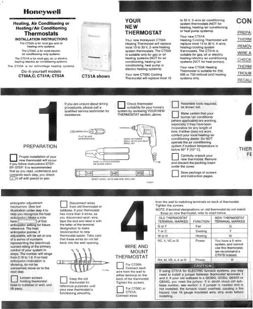
Heating, Air Conditioning or<br />
Heating/Air Conditioning<br />
<strong>Thermostat</strong>s<br />
INSTALLATION INSTRUCTIONS<br />
The CT50A is for most gas and oil<br />
heating-only systems.<br />
The CTSOC is for most electric<br />
air condmoning-only systems.<br />
The CTSlA is for most gas, oil, or electric<br />
healing/electric air conditioning systems<br />
The CT53A is for millivoltage heating systems.<br />
Do-it-yourself models<br />
CT5OA,C; CT51A; CT53A<br />
CPfilA shown<br />
YOUR<br />
NEW<br />
THERMOSTAT<br />
Your new <strong>Honeywell</strong> CT50A<br />
Heating <strong>Thermostat</strong> will replace<br />
most 15 to 30 V, 2-wire heating<br />
system thermostats. The CT50A<br />
is suitable only for gas or oil<br />
heating systems (NOT for air<br />
conditioning, heating/air<br />
conditioning, heat pump or<br />
electric heating systems).<br />
Your new CT5OC Cooling<br />
<strong>Thermostat</strong> will replace most 15<br />
to 30 V, 3-wire air conditioning<br />
system thermostats (NOT for<br />
heating, heating/air conditioning<br />
or heat pump systems).<br />
Your new CT51 A<br />
Heating/Cooling <strong>Thermostat</strong> will<br />
replace most 15 to 30 V, 4-wire.<br />
heating/ cooling system<br />
thermostats. The CT51A is<br />
suitable for gas, oil or electric<br />
heating/electric air conditioning<br />
systems (NOT for heat pumps).<br />
Your new CT53A Heating<br />
<strong>Thermostat</strong> is suitable for 250,<br />
500 or 750 millivolt (mV) heating<br />
systems only.<br />
PREPAI<br />
REMOL<br />
WIRE A<br />
TROUB<br />
If you are unsure about wiring<br />
procedures, please call a<br />
qualified service technician for<br />
assistance.<br />
Check thermostat<br />
suitability lor your home’s<br />
system by reviewing YOUR NEW<br />
THERMOSTAT section, above.<br />
FLAT BLADE<br />
SCREWDRIVER<br />
HAND OR POWER<br />
DRILL WITH 3/16 INCH<br />
DRILL BIT<br />
Proper installation of your<br />
new thermostat will occur<br />
if you follow instructions STEP-<br />
BY-STEP. It is recommended<br />
that as you read, understand and<br />
complete each step, you check<br />
it off with pencil or pen.<br />
WIRE CUTTER/STRIPPER<br />
OR SHARP KNIFE<br />
SPIRIT LEVEL OR PLUMB BOB AND LINE<br />
and discard the<br />
under the cover.<br />
Save package of screws<br />
and instruction pages.<br />
11.95%<br />
anticipator adjustment<br />
Disconnect wires<br />
from old thermostat or<br />
subbase. If your thermostat<br />
has more than 2 wires, as<br />
you disconnect each wire,<br />
tape the end and label it with<br />
the letter of the terminal<br />
designation to make<br />
reconnection to new<br />
thermostat easier. Take care<br />
that these wires do not fall<br />
back into the wall opening.<br />
WiRE AND<br />
MOUNT<br />
from the wall to matching terminals on back of thermostat.<br />
Tighten the screws.<br />
NOTE: If terminal designations on old thermostat do not match<br />
those on new thermostat, refer to chart below.<br />
system, and callnot<br />
Keep the old<br />
thermostat for<br />
reference purposes until<br />
your new thermostat is<br />
functioning smoothly.<br />
For CTSOA:<br />
Connect each<br />
rom the wall to<br />
either terminai on the<br />
back of the thermostat.<br />
Tighten the screws.<br />
For CT50C or<br />
Cf51 A:<br />
Connect wires
Printed I<br />
REMOVING OLD<br />
THERMOSTAT<br />
If you have an<br />
electric furnace. you<br />
need to determine how your<br />
fan is controlled Turn it on<br />
and adjust your present<br />
thermostat so the heat<br />
comes on, while observing<br />
when the fan comes on If the fan comes<br />
on immediately you need to add the<br />
jumper noted in section 4 between<br />
terminals 1 & 2 If there is a noticeable<br />
delay before the fan comes on, there IS<br />
no need to add the jumper because your<br />
furnace controls the fan<br />
Begin by turning off power to the<br />
0 heating/air conditioning system at<br />
the main fuse panel Most residential<br />
systems have a separate switch box or<br />
circuit breaker for disconnecting power<br />
to the furnace<br />
Remove cover of old thermostat-<br />
0 cover normally snaps off when<br />
pulled firmly from the bottom If it resists.<br />
check for a screw that locks the cover on<br />
For CT50A or CTSIA installation<br />
0 before removing the old<br />
thermostat from the wall, look at it<br />
carefully to locate ihe heat<br />
-
4 WIRE AND MOUW .THERMOSTAT wntinued)<br />
Recheck for level positioning, and firmly<br />
tighten both mounting screws<br />
If installing CTSOAor CT51 A, makssure<br />
CI you Aave the turf- {anticipator setting)<br />
for your system. This is the number you wrote in<br />
the box in step 3 If you were unable to find the<br />
current draw for step 3. this information can be<br />
found printed on the primary control at the<br />
furnace. The primary control is usually a gas<br />
valve, zone valve, or a retay or burner control box<br />
with the thermostat wires connected to it. For<br />
electric heat, you need to add the :. n relay<br />
current, usually 0 2 to 0.4 A.<br />
ZONE VALVE<br />
OIL BURNER CONTROL<br />
SHOWS<br />
CURRENT DRAW<br />
s LOW<br />
AGE<br />
TO<br />
BURNER<br />
NT DRAVI<br />
CHECK OUT THE<br />
THERMOSTAT<br />
To prevent possible compressor<br />
damage, do not<br />
operate air conditioning if<br />
outdoor temperature is<br />
below 50" F [lo0 C]. Once<br />
the air conditioner is off,<br />
do not turn it on for 5<br />
minutes: this action will<br />
prevent compressor<br />
damage.<br />
On the CT51A, the system<br />
switch controls as follows<br />
HEAT-heating system only<br />
operates.<br />
OFF-heating and air conditioning<br />
systems are disconnected<br />
COOL-air conditioning system<br />
only operates.<br />
The fan switch controls as<br />
follows:<br />
AUTO-fan operates when<br />
heating or air conditioning<br />
system operates<br />
ON-fa<br />
ousl<br />
rates co<br />
NOTE In the following instruction,<br />
disregard heating or air<br />
applicable to your syst<br />
heating/air conditioning<br />
system<br />
Observe system operation<br />
for at feast one cycle on<br />
both heating and air conditioning.<br />
To observe.<br />
Place the system switch<br />
0 at HEAT position and fan<br />
switch at AUTO. Move the temperature<br />
setting laver 10" F [So C]<br />
above room temperature. The<br />
heating equipment should turn<br />
on A short warm-up period may<br />
be required before the system<br />
fan turns on.<br />
Place system switch at<br />
0 COOL position and move<br />
temperature setting lever 10" F<br />
[So C] below room temperature.<br />
The arr conditioning equipment<br />
should turn on and the system<br />
fan should turn on.<br />
NOTE Some systems have a time<br />
delay that can prevent operation<br />
up to 5 minutes.<br />
0<br />
Turn the fan switch to ON.<br />
The system fan should turn<br />
on, and operate continuously.<br />
The system blower should continue<br />
to operate at any system<br />
switch or thermostat setting.<br />
TYPICAL GAS VALVE<br />
ii.iaic<br />
On the CT50A or CT51A, set heat<br />
anticipator indicator at rating printed on<br />
primary control.<br />
WL I<br />
{MOSTAT<br />
'ING<br />
Adjuslablt,<br />
Hea'<br />
Ari c<br />
Set;[.<br />
Press the thermostat cover firmly onto the<br />
0 mounting clips<br />
I 1-<br />
On CTSlA, place the system<br />
and fan switches at<br />
the desired settings for operation.<br />
On all models, move the<br />
temperature setting lever<br />
to the desired temperature comfort<br />
level
I<br />
I<br />
TROUBLESHOOTING<br />
Your <strong>Honeywell</strong> thermostat requires little or no attention. Most problems can generally be traced to the following:<br />
NOTE: If your system is heating-only or air conditioning-only, disregard sections not applicable to your system.<br />
SYMPTOM<br />
No heat<br />
-_____<br />
Furnace turns on<br />
and off.<br />
Major swings in<br />
^_^^_^<br />
1.. ..^<br />
PROBLEM<br />
System switch at OFF or<br />
COOL Position.<br />
Blown fuse or tripped<br />
circuit breaker<br />
Furnace power switch is<br />
on QFF.<br />
No pilot flame<br />
Improper connections to<br />
thermostat.<br />
Defective thermostat.<br />
(Here’s how you tell:<br />
Remove the thermostat<br />
from the wall. Disconnect<br />
wire from W terminal.<br />
Touch W wire to<br />
R terminal. The thermostat<br />
is detective if the<br />
burner comes on.)<br />
Other.<br />
Burner ON period is too<br />
short,<br />
Burner ON period<br />
:- *^^ ,---<br />
CORRECTI~E A m<br />
Move switch to HEAT<br />
position.<br />
Replace fuse or reset<br />
circuit breaker<br />
Switch to ON<br />
Relight pilot flame per<br />
furnace manufacturer’s<br />
instructions<br />
With power to furnace<br />
OFF, tighten all mounting<br />
and terminal screws. Repair<br />
frayed or broken<br />
wires.<br />
Exchange the thermostat<br />
(see Warranty).<br />
Contact a qualified service<br />
technician for assistance.<br />
Remove the thermostat<br />
cover and move the heat<br />
anticipator lever COUNTER-<br />
CLOCKWISE n one<br />
scale mark. Replace the<br />
cover and wait several<br />
hours for the system to<br />
stabilize.<br />
Remove the thermostat<br />
^^..^_ .-A -^..^ A&.^ LA-.<br />
SYMPTOM<br />
_.__-<br />
PROBLEM<br />
<strong>Thermostat</strong> setting <strong>Thermostat</strong> is not level.<br />
and thermometer<br />
reading disagree.<br />
No air Condltloning<br />
<strong>Thermostat</strong> affected by<br />
drafts or radiant heat.<br />
<strong>Thermostat</strong> is out of calibration.<br />
Thermometer is out of<br />
calibration<br />
-<br />
System switch in in OFF<br />
or HEAT position.<br />
Blown fuse or tripped<br />
circuit breaker<br />
Compressor switch (located<br />
outdoors) is turned<br />
OFF<br />
Improper connections to<br />
thermostat<br />
Defective thermostat.<br />
(Here’s how you tell.<br />
Remove the thermostat<br />
from wall Disconnect<br />
wire from Y terminal<br />
Touch Y wire to terminal<br />
R. The thermostat is defective<br />
if the compressor<br />
CORRECTIVE ACTION<br />
Recheck the thermostat<br />
position on wall. Use a<br />
bubble level to make sure<br />
it’s level. See step 4.<br />
Contact a qualified service<br />
technician to change the<br />
location. The thermostat<br />
should be about 5 ft [1.5<br />
m] above the floor and on<br />
an inside wall.<br />
Contact a qualified service<br />
technician to recalibrate<br />
the thermostat.<br />
Recalibrate. See step 8.<br />
Move siitc-h to cooi<br />
position.<br />
Replace fuse or reset<br />
circuit breaker.<br />
Move switch to ON position.<br />
With power to furnace<br />
OFF, tighten all mounting<br />
and terminal screws. Repair<br />
broken wires.<br />
Exchange the thermostat.<br />
See Warranty.


