

Honeywell Standard Non-Programmable Thermostat (CT5X) - Standard Non-Programmable Thermostat Installation Manual (French)
Honeywell Standard Non-Programmable Thermostat (CT5X) - Standard Non-Programmable Thermostat Installation Manual (French)
Honeywell Standard Non-Programmable Thermostat (CT5X) - Standard Non-Programmable Thermostat Installation Manual (French)

You also want an ePaper? Increase the reach of your titles
YUMPU automatically turns print PDFs into web optimized ePapers that Google loves.
i<br />
I<br />
TALU<br />
CTSOA, CT51A, CT53A<br />
THERMOSTATS<br />
CTSOA Heating only<br />
Compatible with most 2 wire gas<br />
and oil heating systems<br />
CTSlA HeatinglCooling<br />
Compatible with most 4 wire gas<br />
and oil heating systems<br />
CT53A Millivolt heatlng only<br />
For 250,500, 750 millivolt systems<br />
Form No. 69-02658-2 Rev. 9-97 R.T. CT51 A<br />
1<br />
PREPARATION FOR<br />
INSTALLATION<br />
Assemble tools required;<br />
screwdriver level wirestripper<br />
IMPORTANT<br />
If the model number under the cover of your existing thermostat begins with the same<br />
series of numbers as listed below, the <strong>Honeywell</strong> thermostat is compatiblewith-and can<br />
be installed on-yourexisting heating system. If notwe recommend that you contact your<br />
local heating contractor or dealer for professional installation.<br />
T11~l~KMA1K54/r8022/T81~819K8~8~K~K87K~H<br />
TMl1KM81C/TM17H-124E/lC30-10/1 E30-10/1E30-11/1E30-910/lF30-10/1 F30-301/<br />
1F30-311HF30-13/1F30-910<br />
CT53A FOR MILLIVOLT SYSTEMS-Replaces TS822/1 E30-M)9/1 F30-604/1 F30-910<br />
0<br />
Make certain that your burner is operating especially if it has been<br />
inoperative for any length of time. If it does not work, contact your local heating<br />
contractor.<br />
2<br />
REMOVING OLD<br />
THERMOSTAT<br />
Begin by turning off power to the heating system at the main fusepanel.Most<br />
residential systems have aseparate switch boxorcircuit breaker fordisconnecting<br />
Efonehrna-*<br />
Moveowerof dd thermostatcover normally snaps off when pulled firmly from<br />
the bottom. if it resists, check for a screw that locks the cover on.<br />
For CTMA, CT51A <strong>Installation</strong><br />
thermostat from the wall, look at it carefully to locate the<br />
ent mechanism. See illustration under step 3 to help you<br />
Make a note here<br />
of the antidpator setting<br />
be set to exactly the same setting. The heat antidpator<br />
at one of a series of numbers representing the arrrent<br />
indication is showing, do not be concerned; move on to the next step.<br />
0 Loosen screws holding thermostat to the wall, and lift away.<br />
Retain the old thermostat for reference purposes until your newthermostat<br />
is funotioning smoothly.<br />
service. for a period of one (1) year from<br />
thewanantyperkd, aprcductis defective<br />
Thiswarrantyshall not apply if it shown by <strong>Honeywell</strong> that the defect or malfunctbn was caused by<br />
damage which occurred while the product was in the pogsesslon of aconsumer.<br />
Hineywell's sole responsibility shall be to repalr or replace the product wkhln the therms stated<br />
above. HONEYWELL SHALL NOT BE LIABLE FOR ANY CONSEQUENTIAL DAMAGES RESULT-<br />
INGFROM ANY BREACHOFANY WARRANTY. EXPRESSEDOR 1MPLIED.APPLiCABLETOTHIS<br />
PRODUCT. Some provinces and territories do not albw the exclusbn or limitation of consequential<br />
damages, so this limilation may nd apply to you.<br />
THIS WARRANTY IS IN LIEU OF ALL OTHER WARRANTIES, EXPRESSEDOR IMPLIED, AND<br />
THE WARRANTIES OF MERCHANTABILITY AND FITNESS FOR A PARTICULAR PURPOSE ARE<br />
HEREBY EXCLUDEDBMONDTHEONEYEARDURATDNOFTHE WARRANTY.Somepmvinces<br />
andtenlorriesdorotalbwlimlatbnonthedurationo(animpliedwarrarly,sotheabovellmlationmay<br />
not apply to you.<br />
This warranty glves you spedfic legal rights and you may ako have other rights which vary<br />
according to pmvlnceorterrkory. This warranty is In addition to and not a modlication of or subtractbn<br />
fmmwarrantiesandotherrights andremedies contained InStatutesrehtingtothesaleofthlsprodud.<br />
BatterieslncludedwlthBatreryCperated Productsareexdudedfrnmthewanantyastheyarend<br />
manufactured by <strong>Honeywell</strong> Umiled. Such baneries are covered by battery manu(aclurePs Warrantv<br />
if any.
YOUR HONEYWELL THERMOSTAT<br />
Your new <strong>Honeywell</strong> CT50A Heating <strong>Thermostat</strong> will replace most 15 to 30 V, 2-wire<br />
heating system thermostats. The CT5OA will control most gas or oil heating systems<br />
(NOT for heating/cooling or heat pump systems).<br />
Your new <strong>Honeywell</strong> CT51A Heating/Cooling <strong>Thermostat</strong> will replace most 15 to 30 V.<br />
4-wire, heatingkooling system thermostats. The CT51A is suitable only for gas or oil<br />
heatingkooling systems (NOT for heat pump systems).<br />
Your new <strong>Honeywell</strong> CT53A Heating <strong>Thermostat</strong> is suitable for 250,500 or 750 millivolt<br />
(mV) heating systems only.<br />
3<br />
WIRE AND MOUNT<br />
-NEW THERMOSTAT -<br />
Connect one of the 2 wires from the wall to each of the two terminals on the back<br />
of the thermostat. Tighten the screws.<br />
Connect4wires from thewall to matching terminalson backof thermostat.Tighten<br />
the screws.<br />
CAUTION<br />
0<br />
Connect wires to R and W for 750 mV systems. CQnRect to R and Y Par 250 or 500<br />
Q.<br />
mV systems. Tighten the screws.<br />
Grasp the thermostat cover at the top and bottom with one hand. Pull<br />
outwardon the topedgeofthe thermostatcover until itsnaps freeofthe thermostat<br />
Carefully remove and discard the red plastic pin located above the mercury switch.<br />
0 This pin protects this switch during shipment.<br />
Fasten thermostat to the wall with one of the screws supplied, using the top<br />
mounting hole.<br />
Place your level across the top of the<br />
level it. Start the second<br />
screw, supplied, in the center of the bo<br />
Ole.<br />
Recheck for level positioning then firm1<br />
ounting screws.<br />
1<br />
I7<br />
P<br />
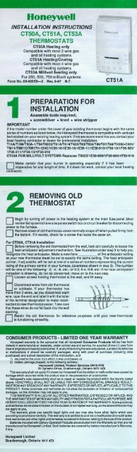
If Installing CT50A, CT5lA<br />
MAKE SURE you have the current (anticipator setting) for your system.This is the<br />
number you wrote in the box in step 2. If you were unable to find the current draw<br />
or step 2 this information can be found printed on the primary control at the furnace.<br />
The primary control is usually a gas valve, zone valve, or a relay or burner control box<br />
with the thermostat wires connected to it. (See illustrations Of 3 types of primary controls<br />
below).<br />
On the CT50A CTSlA<br />
OIL BURNER CONTROL<br />
TERMINAL SCREWS<br />
ICTSlA SYOWN\<br />
TOP MOUNTING HOLE<br />
ADJUSTABLE HEAT<br />
ANTICIPATOR SETTING LEVER<br />
(CT5OA, CT5lA ONLY)<br />
MOUNTING CLIPS<br />
(FOR COVER)<br />
FAN SWITCH<br />
(CT51A ONLY)<br />
SYSTEM SWITCH<br />
(CT51A ONLY)<br />
BOTTOM MOUNTING HOLE<br />
TEMPERATURE SETTING LEVER
I<br />
IHtHMW3lAI<br />
PERFORMANCE CHECK<br />
On the CT51A. the system switch controls as follows:<br />
HEAT-heating system only operates.<br />
OFF-heating and cooling systems are disconnected.<br />
COoL-woling system only operates.<br />
The fan switch controls as follows:<br />
AUTO-fan on when heating or cooling system operates.<br />
ON-fan operates continuously.<br />
I NOTE: In the following instruction, disregard coonng directions if not applicable 10 your<br />
system.<br />
R<br />
er to the heatinglcooling system.<br />
To observe: Place the system switch at HEAT position and fan switch at AUTO.<br />
Move the temperature setting lever to 10" F (6" C) above room temperature. The<br />
rnace should turn on. A short warm-up period may be required before the system fan<br />
0<br />
Place system switch at COOL position and move temperature setting lever 10" F<br />
On. (6' C) below room temperature. The cooling equipment should turn on and the<br />
system fan should turn on.<br />
NOTE: Some systems have a time delay that can prevent operation up to 30 seconds.<br />
0<br />
Turn the fan switch to ON. The system fan should turn on, and operate continuously.<br />
The fan should continue to operate at any system switch or thermostat<br />
setting.<br />
Your <strong>Honeywell</strong> thermostat requires little or no attention.<br />
Most problems can generally be traced to the following:<br />
TOM-No heal<br />
.EM<br />
CORRECTIVE ACTION<br />
Blown fuse or tripped .. circuit breaker.<br />
Furnace power switch is turned OFF.<br />
No pilot flame.<br />
Improper connections to thermostat.<br />
Defective thermostat. (Here's how you<br />
tell. Turn power to furnace OFF. Then<br />
remove the thermostat from the wall.<br />
Disconnect one wire from the back of<br />
the thermostat. Turn power to We<br />
furnace ON. Touch loose wire to wire<br />
still connected. The thermostat is<br />
defective if the burner comes on.)<br />
Replace fuse or reset circuit breaker.<br />
Switch to ON.<br />
Relight pilot flame per furnace<br />
manufacturer's instructions.<br />
With Power to furnace OFF, tighten all<br />
mounting and terminal screws. Repair<br />
broken wires.<br />
Exchange the thermostat (See warranty). m-<br />
SYMPTOM-Furnace turns an and off<br />
Burneron period is tw short. Adjust the heat anticipator lever<br />
'<br />
CLOCKWISE none scale mark. Wait at<br />
least several hours to stabilize.<br />
SYMPTOM-Major swings - in temperature tareater .- than lo C when temperature<br />
stable).<br />
Burneron period is too long. Adjust the heat anticipator lever COUNTER-<br />
CLOCKWISE fi one scale mark. Wait<br />
several hours for the system to stabilize.<br />
SYMPTOM-<strong>Thermostat</strong> selling and thermostat reading disagree<br />
<strong>Thermostat</strong> is not level.<br />
Recheck the thermostat position on wall. Use<br />
a level to make sure it is level. See step #3.<br />
<strong>Thermostat</strong> affected by drafts or<br />
radiant heat.<br />
<strong>Thermostat</strong> is out of calibration.<br />
SYMPTOM-No Cooling<br />
System switch in OFF or HEAT<br />
position.<br />
Blown fuse or tripjed circuit breaker.<br />
Condenser switch (located outdoors)<br />
is turned OFF.<br />
Improper connections to thermostat.<br />
Call furnace technician to change the location.<br />
The thermostat should be about 5 ft. [I.5 m]<br />
above the floor and on inside wall.<br />
Call furnace technician.<br />
Move switch to COOL position.<br />
Rep1 fuse of reset circuit breaker.<br />
Move switch to ON position.<br />
With power to furnace OFF, tighten all<br />
mounting and terminal screws. Repair<br />
broken wires.<br />
Defective thermostat. (Here's how you<br />
tell: Turn power to cooling system<br />
OFF. Then remove the thermostat<br />
from wall. Disconnect wire from Y terminal.<br />
Turn power to cooling system<br />
ON. Touch Y wire to terminal R. The<br />
thermostat is defective if the compressor<br />
starts. Some systems have a time<br />
delay, so allow at least 2-3 minutes.)<br />
Other.<br />
Exchange the thermostat (see warranty).<br />
Contact service technician for assistance.
<strong>Honeywell</strong><br />
NOTICE D'INSTALLATION<br />
THERMOSTATS<br />
CT50A, CT51A, CT53A<br />
CTSOA (pour chauffage seulement)<br />
Convient B la plupart des systemes bifilaires<br />
de chauffage au gaz ou au mazout<br />
CT<br />
250,500 ou 750 millivolts CT51 A<br />
PuMlcatlon no 6942658-2 Revu 9-97 R.T.<br />
1<br />
PREPARATION AVANT<br />
L'INSTALLATION<br />
Rassemblez les outils necessaires:<br />
Tournevis Niveau h bulle Pince B denuder<br />
IMPORTANT<br />
Si le numero de modble indiqub A I'intbrieur du couvercle de votre thermostat actuel<br />
commence par les memes numeros de serie que les numeros ci-dessous, le<br />
thermostat convient et peut &We install6 avec votre systbme de chauffage actuel. Si<br />
cela n'est pas le cas, nous vous recommandons de contacter I'entrepreneur ou le<br />
dbtaillant en chauffagerefroidissement de votre &ion pour effectuer I'installation.<br />
Tll AlTl99K50A-1 KMK802~81 AIT819K82~83/r834K~K87K~KH269-<br />
C401KM11KM8lCKMl7H-l24EllC30-1011E30-10~1E30-11/1E30-910/1F30-30lI<br />
1F30-31 lllF30-13/1F30-910.<br />
CT53A POUR SYSTkMES EN MILLIVOLTS - Remplace les thermostats TS822/<br />
1 E30-609/1 F30-60411 F30-910.<br />
Assurez-vous que wtre appareil de chauffage fonctionne, particulibrernent<br />
0 s'il n'a pas btb utiliSe depuis un certain temps. S'il ne fonctionne pas,<br />
communiquez avec wtre entrepreneur en chauffage.<br />
_ _ ~ ___ - - _ -<br />
-<br />
B<br />
RETRAIT DE L'ANCIEN<br />
THERMOSTAT<br />
Coupez I'alimentation du systbme de chauffage au panneau principal. La<br />
plupart des systemes dsidentiels ont un disjoncteur distinct pour couper<br />
imentation au systbme de chauffage.<br />
Enlevez le couvercle de I'ancien thermostat. Si le couvercle ne s'enlbve pas<br />
0 lonque MUS le tirez fermement par le bas, it y a probablement une vis qui<br />
retient le couvercle en place.<br />
<strong>Installation</strong> du CTNA, CT51A<br />
Avant d'enlever I'anden thermostat du mur, examinez attentivement le<br />
0 mbmnisme de kglage de la resistance antidpatrice de chaleur. (L'illustration A<br />
I'Btape 3 vous permet de reconnaftre la rbsistance). Notez sur la ligne suivante le<br />
r6glage de la ksistance car votre nwveau thermostat doit &re kglb exactement A la<br />
meme valeur. Si I'indicateur de la ksistance antidpatrice est rhlable, il indiquera<br />
I'un des chiffres reprbsentant I'intensitb du courant de I'organe de comrnande de<br />
rappareit de chauffage (wir emmples &I%tqe3).CWea so~t: 2, .4, .8 stc. ou<br />
0.2,0.4,0.8 etc. Si le thermostat ne possede pas de rbsistance antidpatrice, passez<br />
Eapa suivante.<br />
Desserrez les vis qui retiennent le thermostat au mur et retirez le thermostat.<br />
0<br />
Wbranchez les fils de I'ancien<br />
thermostat ou de la plaque murale. Si<br />
votre thermostat a plus de 2 fils, enroulez le<br />
bout de chaque fit d'un tuban adhbsif et<br />
inscrivez-y la lettre correspondant 8 la bome<br />
du thermostat pour faciliter le raccordement.<br />
5<br />
Assurez-vous que les fils ne glissent pas<br />
lemur.<br />
Gardez I'ancien thermostat pour consultation ultbrieure, jusqu'8 ce que wtre<br />
nouveau thermostat fonctionne de facon approprik.<br />
PRODUrrS AU CONSOMMATEUR-GARANTIE RESTREINTE POUR UN AN
VOTRE THERMOSTAT HONEY WELL<br />
Votre nouveau thermostat CT50A de <strong>Honeywell</strong> peut servir B remplacer la<br />
plupart des thermostats bifilaires 15 h 30 V c.a. des systbmes de chauffage. Le<br />
CT5OA assure la regulation de la plupart des systbmes de chauffage au gaz ou au<br />
mazout (NE convient PAS aux systemes de chauffagerefroidissement ou aux<br />
pompes B chaleur).<br />
Votre nwveau thermostat CTSIA de <strong>Honeywell</strong> peut servir B remplacer la<br />
plupart des thermostats B 4 fils 15 h 30 V c.a. des systbmes de chauffage<br />
refroidissement. Le CT51A convient a x systbmes de chauffagerefroidissement au<br />
gaz ou au mazout seulement (NE convient PAS aux pompes B chaleur).<br />
Votre nouveau thermostat CT53A de <strong>Honeywell</strong> convient aux systbmes de<br />
chauffage 250,500 ou 750 millivolts (mV) seulement.<br />
I<br />
NOUVEAU THERMOSTAT<br />
1 Raccordez chacun des 2 fils du mur B une borne B I'arribre du thermostat.<br />
Jadhle CT51<br />
"I<br />
;,I-<br />
.
n<br />
I<br />
VERIFICATION DU<br />
FONCTIONNEMENT DU<br />
THERMOSTAT<br />
_. T51A.<br />
Le commutateur du systbrne comrnande les fonctions suivantes:<br />
HEAT-le systbme de chauffage seulement fonctionne.<br />
OFF-les systemes de chauffage et de refroidissement cessent de fonctionner.<br />
COOL-le systbme de refroidissement seulement fonctionne.<br />
L'interrupteur du ventilateur comrnande les fonctions suivantes:<br />
AUTWe ventilateur fonctionne en m&me temps que les systbmes de chauffage<br />
ou de refroidissement.<br />
Owe ventilateur fonctionne de fawn continue.<br />
REMARQUE: Ne suivez pas les directives concernant le fonctionnement en mode de<br />
refroidissement si elles ne s'appliquent pas I votre systbme.<br />
B<br />
Alimentez le systbme de chauffagerefroidissernent.<br />
Observe2 le fonctionnement du systbme durant un cycle complet en mode de<br />
chauffage et en mode de refroidissernent.<br />
&<br />
Pour observer : placez le commutateur du systhe I HEAT et I'interrupteur du<br />
0 ventilateur I AUTO. Mplacez le doigt de reglage de la temperature jusqu'h 6°C<br />
(10 OF) au-dessus de la temperature ambiante. Le systbme de chauffage devrait se<br />
mettre en marche et le ventilateur devrait fonctionner apr&s un court delai.<br />
Placez le commutateur du syst6me I COOL et deplacez le doigt de reglage de<br />
la temperature jusqu'I 6 "C (10 OF) au-dessous de la temperature ambiante. Le<br />
me de refroidissement et le ventilateur devraient se mettre en marche.<br />
REMARQUE: Certains systbmes ont un dispositif de temporisation qui peut retarder<br />
le fonctionnement jusqu'h 30 secondes.<br />
0<br />
Placez I'interrupteur du ventilateur I ON. Le ventilateur devrait fonctionner de<br />
fawn continue. Le ventilateur devrait continuer a fonctionner I n'importe quel<br />
r6glage du systbme de chauffage ou de refroidissement.<br />
Inu c<br />
Votre them<br />
in n&essite trbs peu d'entretien. Vous<br />
pourrez regler la plup& des problbmes en suivant les directives a-<br />
dessous:<br />
SYMPTdME-Pas de chaleur<br />
PROBL~ME<br />
MESURE A PRENDRE<br />
Le fusible a fondu ou le disjondeur est Remplacer le fusible ou rbnclencher le disjoncteur.<br />
dhlench6.<br />
Le systbme de chauffage est hors tension. Menre le systbme de chauffage mu8 tensbn.<br />
La vellleuse ne s'allume pas.<br />
Allumer a rnuveau la wllleuse selon les Instructions<br />
du fabricant.<br />
Mauvals racmrdement au therrmstat Mettre le connnutateur a OFF et v9rifler Is vls de<br />
fbtatbn et les vis des bornes. Reparer les fils his&.<br />
Le thermostat est Mectueux. (Pour<br />
vMer le cas. Mettre le thermostat & OFF.<br />
Enlever le thermostat du mur. DBbrancher<br />
un fll & I'anibre du thermostat. Mettre le<br />
thermostat & ON. Placer le fil dBbranch6<br />
avec le 111raccord6. Le thermostat est<br />
d6fectueux si ie baleur s'allume). khanger le thermostat (wir garantie).<br />
AUtre.<br />
S'adresser & un technlden qualifi6.<br />
SYMPTdME-Le systbme de chauffage fonctionne et s'arrate.<br />
Le bmleur ne fondionne ms asez DBDlacer le dolm de ta resistance antldDatrice dans le<br />
longtemps<br />
SENS HORAIRk r\ d'une valeur. Abendre,.<br />
quelques heures pour que le systbme se statnlse.<br />
SYMPTtiME-hrts imwrtants de temDBrature blus de 1 O C lorsaue la<br />
tempbraturo e91 stable).'<br />
Le brOleur fonctbnne trop bngtemps.<br />
oephcer le doigt de la reSlstance antidpatria, dans le<br />
SENS ANTIHORAIRE A d'une valeur. Attendre<br />
quelques heures pour due le systbme se stabilise.<br />
SYMPT6ME--La temperature ne correspond pas au hglage.<br />
Le thermostat n'est pas de niveau.<br />
V6dler & nouveau la position du thermostat sur le<br />
mur. Utlllser un niveau & bulb & ce( Met. (Vdr retape<br />
3).<br />
S'adresser & un technlden qualifi6 pour changer<br />
I'emplacemnt. Le thermostat doit &re a une hauteur<br />
de 1.50 m (5 DI) du Dlancher 64 sur un mur lnt6rleur.<br />
S'adressera un techniaen qualli6.<br />
Le thermostat est affect6 par les<br />
cwrants d'alr ou par de la chaleur<br />
rayonnante.<br />
thermostat n'est plus Btalonn6.<br />
SYMPT(9ME-Le sydbme de refroidissement ne fonctionne pas.<br />
Le mmmutateur du ~~8th~ est &OFF ou<br />
& HEAT.<br />
Le fusible a fondu ou le dlsjondeur est<br />
d8dench6.<br />
L'lntempteur du mndensateur (sltu6&<br />
I'extdrleur) est a OFF.<br />
Mauvals raccordement au thermostat.<br />
<strong>Thermostat</strong> d&ectueux. (Pour vMfier le<br />
cas. Mettre le systbme de refroldissement<br />
& OFF. Enlewr le thermostat du mr.<br />
DBbrancher le fU de la borne Y. Placer le<br />
iil Y sur la borne R. Le themmtal est<br />
ddfectueux sl 18 mmpresseur se met en<br />
marche. Certains systbmes ont un<br />
dispositl de temporlsatbn; 11 est necsSMire<br />
d'albuer 2 & 3 minutes au molns.)<br />
oeplacer le commutateur & COOL.<br />
Remplacer le fusible ou rbnclencher le disjoncteur.<br />
Mphcer finterrupteur & ON.<br />
Meltre le thermostat &OFF et verifier les via de<br />
fiiatbn et les vis des bornes.<br />
_-<br />
RBparer les iiki kls6s.<br />
-<br />
&hanger le thermostat. (Volr lamrantie).<br />
AUtre. S'adrGser & un techniden qualfi6. .


