RO eBook Part 15 Control Philosophy

Create successful ePaper yourself
Turn your PDF publications into a flip-book with our unique Google optimized e-Paper software.
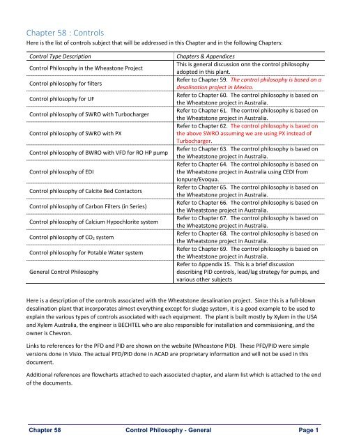
Chapter 58 : <strong>Control</strong>s<br />
Here is the list of controls subject that will be addressed in this Chapter and in the following Chapters:<br />
<strong>Control</strong> Type Description<br />
<strong>Control</strong> <strong>Philosophy</strong> in the Wheastone Project<br />
<strong>Control</strong> philosophy for filters<br />
<strong>Control</strong> philosophy for UF<br />
<strong>Control</strong> philosophy of SW<strong>RO</strong> with Turbocharger<br />
<strong>Control</strong> philosophy of SW<strong>RO</strong> with PX<br />
<strong>Control</strong> philosophy of BW<strong>RO</strong> with VFD for <strong>RO</strong> HP pump<br />
<strong>Control</strong> philosophy of EDI<br />
<strong>Control</strong> philosophy of Calcite Bed Contactors<br />
<strong>Control</strong> philosophy of Carbon Filters (in Series)<br />
<strong>Control</strong> philosophy of Calcium Hypochlorite system<br />
<strong>Control</strong> philosophy of CO 2 system<br />
<strong>Control</strong> philosophy for Potable Water system<br />
General <strong>Control</strong> <strong>Philosophy</strong><br />
Chapters & Appendices<br />
This is general discussion onn the control philosophy<br />
adopted in this plant.<br />
Refer to Chapter 59. The control philosophy is based on a<br />
desalination project in Mexico.<br />
Refer to Chapter 60. The control philosophy is based on<br />
the Wheatstone project in Australia.<br />
Refer to Chapter 61. The control philosophy is based on<br />
the Wheatstone project in Australia.<br />
Refer to Chapter 62. The control philosophy is based on<br />
the above SW<strong>RO</strong> assuming we are using PX instead of<br />
Turbocharger.<br />
Refer to Chapter 63. The control philosophy is based on<br />
the Wheatstone project in Australia.<br />
Refer to Chapter 64. The control philosophy is based on<br />
the Wheatstone project in Australia using CEDI from<br />
Ionpure/Evoqua.<br />
Refer to Chapter 65. The control philosophy is based on<br />
the Wheatstone project in Australia.<br />
Refer to Chapter 66. The control philosophy is based on<br />
the Wheatstone project in Australia.<br />
Refer to Chapter 67. The control philosophy is based on<br />
the Wheatstone project in Australia.<br />
Refer to Chapter 68. The control philosophy is based on<br />
the Wheatstone project in Australia.<br />
Refer to Chapter 69. The control philosophy is based on<br />
the Wheatstone project in Australia.<br />
Refer to Appendix <strong>15</strong>. This is a brief discussion<br />
describing PID controls, lead/lag strategy for pumps, and<br />
various other subjects<br />
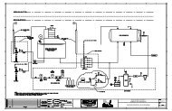
Here is a description of the controls associated with the Wheatstone desalination project. Since this is a full-blown<br />
desalination plant that incorporates almost everything except for sludge system, it is a good example to be used to<br />
explain the various types of controls associated with each equipment. The plant is built mostly by Xylem in the USA<br />
and Xylem Australia, the engineer is BECHTEL who are also responsible for installation and commissioning, and the<br />
owner is Chevron.<br />
Links to references for the PFD and PID are shown on the website (Wheastone PID). These PFD/PID were simple<br />
versions done in Visio. The actual PFD/PID done in ACAD are proprietary information and will not be used in this<br />
document.<br />
Additional references are flowcharts attached to each associated chapter, and alarm list which is attached to the end<br />
of the documents.<br />
Chapter 58 <strong>Control</strong> <strong>Philosophy</strong> - General Page 1
<strong>Control</strong> <strong>Philosophy</strong> in the Wheastone Project<br />
The plant operates in AUTO or MANUAL mode. In MANUAL mode, operators in the centralized control room can start<br />
or stop any unit in the plant thru the plant’s HMI. In this mode, operators will have the flexibility to start and stop any<br />
unit and to alternate the operation of duty/standby units. However, if there are critical alarm conditions that inhibit<br />
the start of a certain unit, that unit will not start.<br />
In AUTO mode, the plant will be controlled by the PLC. In this mode, the start and stop cycles are normally controlled<br />
by liquid levels in the following tanks:<br />
1. UF Filtrate Tank 0T-3613A & 0T-3613B<br />
2. SW<strong>RO</strong> Product Tank T-3608<br />
3. BW<strong>RO</strong> Product Tank T-3618<br />
4. DEMIN Product Storage Tank T-3603<br />
5. Potable Water Storage Tank T-3605<br />
6. Utility Water Distribution Tank<br />
7. IAH (Inlet Air Humidifier) Storage Tank<br />
The entire plant is divided into separate plants that operate independently.<br />
1. The pretreatment plant which consist of the UF<br />
2. The Desalination plant which consist of the SW<strong>RO</strong> only<br />
3. The DEMIN plant which consists of the BW<strong>RO</strong> & EDI<br />
4. The potable water treatment plant<br />
5. The utility water treatment plant<br />
The set of general rules that govern the control of the equipment are:<br />
1. Any piece of component in any equipment must be in AUTO when operating the unit (i.e., pumps, valves,<br />
etc.…). Otherwise, an alarm is initiated followed by abnormal shutdown.<br />
2. All pump stations with Duty/Standby pumps will not alternate automatically if there is FAULT from the duty<br />
pump. Isolation valves for the standby pumps are normally closed. If there is FAULT from the duty pump, an<br />
alarm is initiated and operator must investigate the problem & clear the FAULT. If the duty pump is not able<br />
to operate, the standby pump will become the lead pump until the duty pump is back in service.<br />
3. UF trains will alternate ON & OFF at CEB which is set to be every 8 hours. Each UF train must have equal runtime<br />
to the maximum extent possible. For example, when the CEB cycle begins for a train A1, the PLC will<br />
start the train in the next order in the hierarchy table.<br />
Chapter 58 <strong>Control</strong> <strong>Philosophy</strong> - General Page 2
Bank A1 Bank A2 Bank A3 Bank B1 Bank B2 Bank B3<br />
Position 1 Position 2 Position 3 Position 4 Position 5 Position 6<br />
Filtration<br />
Standby<br />
CEB<br />
Filtration<br />
Standby<br />
Filtration Span =<br />
1-hour<br />
Standby CEB Filtration<br />
CEBSP = 8-hours<br />
(Span between two CEB)<br />
4. SW<strong>RO</strong> trains must alternate daily. Since there are two trains, the lead and lag trains will switch based on 24-<br />
hour timer.<br />
5. The DEMIN system will not operate continuously, so the BW<strong>RO</strong> and EDI trains will alternate or switch the<br />
lead/lag status at every start-up & shutdown. For example, if the EDI train A ran for 6 hours in one day, EDI<br />
train 2 becomes the lead train and will start next when there is call for DEMIN water.<br />
6. Backwash of all carbon filters (De-chlorination of 1 st pass <strong>RO</strong> permeate) and IAH must be performed on a<br />
weekly basis (7-day timer) unless P rises above setpoint. Differential pressure increase that will trigger an<br />
alarm and override the timer. When the units are backwashed by differential pressure, the BW Frequency<br />
timer will be rest to zero. The lead unit will be backwashed first followed by the lag unit. If the differential<br />
pressure alarm is ON in filter A and the filter B is in backwash, the PLC will delay the BW initiation until filter B<br />
BW cycle is complete.<br />
7. Backwash of all calcite filters (Utility & Potable) must be performed on a weekly basis (7-day timer) unless P<br />
rises above setpoint. Differential pressure increase that will trigger an alarm and override the timer. When<br />
the units are backwashed by differential pressure, the BW Frequency timer will be rest to zero. Please note<br />
that whenever the filter requires replenishment of the calcite, the unit must be backwashed manually.<br />
8. For BW<strong>RO</strong> with low-TDS water, shutdown is followed by flushing of the <strong>RO</strong> unit with feedwater while the <strong>RO</strong><br />
HP Pump is OFF. Typically, this is done by the LP (Low-Pressure) <strong>RO</strong> feed water pump. This cycle is called<br />
post-flush. In this case here, the pre-flush and the post-flush cycles are the same. The shutdown sequence<br />
begins with opening the Auto-Flush valve, followed by shutting down the <strong>RO</strong> HP pump, followed by closing<br />
the feed isolation valve after the preset time of Auto-Flush is complete, and last closing the autoflush valve.<br />
The flush period should be set during commissioning of the <strong>RO</strong> train.<br />
9. Some specifications require the BW<strong>RO</strong> to be flushed with permeate water. This is usually recommended<br />
when the feedwater conductivity is high or when TDS is possibly greater than 5000ppm. In this case,<br />
shutdown is followed by flushing of the <strong>RO</strong> unit with permeate water using a dedicated flushing pump while<br />
the <strong>RO</strong> HP Pump is OFF. In this case, a flushing inlet valve on the BW<strong>RO</strong> is required, a dedicated flushing<br />
pump is required, but flushing tank is not required. The storage tank will be used to post-flush the <strong>RO</strong>.<br />
Chapter 58 <strong>Control</strong> <strong>Philosophy</strong> - General Page 3
10. In SW<strong>RO</strong>, the flushing system is integral to the SW<strong>RO</strong> unit. If you have one train or two trains, it is preferable<br />
that each <strong>RO</strong> is equipped with its own flushing tank and flushing pump. If you have multiple train, typically<br />
these trains will share one flushing system. When a <strong>RO</strong> train starts, it is flushed<br />
11. When there is no call for water, the PLC shuts-down the <strong>RO</strong> trains one at a time as the level drops in the<br />
storage tank (depending on how many trains are operating).<br />
Alarm conditions associated with equipment malfunction, or pumps and automated valves not in AUTO will not be<br />
discussed further in this document. In general, all these conditions will generate an alarm when units are in AUTO and<br />
operating under normal conditions:<br />
a) ON/OFF or modulating valves not in AUTO<br />
b) Pumps not in AUTO and not READY or RUNNING when commanded to start<br />
c) Any FAULT or TRIP from a pump<br />
d) Any feedback from limit switches indicating that valve is not in correct status<br />
Any alarm condition will cause the following:<br />
a) All alarms will be displayed on the HMI which requires action by the operator. The operator must<br />
ACKNOWLEDGE and RESET the alarm after investigating the problem.<br />
b) After any type of shutdown (abnormal or normal) on the SW<strong>RO</strong>, the SW<strong>RO</strong> train is flushed immediately.<br />
c) After any type of shutdown (abnormal or normal) on the BW<strong>RO</strong>, the BW<strong>RO</strong> train is flushed immediately.<br />
Chapter 58 <strong>Control</strong> <strong>Philosophy</strong> - General Page 4
Chapter 59 : <strong>Control</strong> <strong>Philosophy</strong> – Filters<br />
Dual Media Filters (Small System with air Scour)<br />
Here is an example of filters used in a desalination project for a plant in Mexico. These sketches are for roughing filter<br />
followed by polishing filter (two filters in series). The Service, air scour, BW, and rinse cycle is applicable to all types of<br />
filters except for large filters.<br />
Please note that most systems do not have two filters in series which is commonly referred to as dual filtration- they<br />
have only one, and most small filters do not have air scour step especially in brackish water application.<br />
Flow Path through Dual Media Filters<br />
The duplex dual media filter consists of two tanks operating in series each contains two layers of media & support<br />
media. Seawater enters the first dual media filter (00GDB01AT101) where particulate is removed. Filtered from the<br />
1 st filter water enters the 2 nd dual media filter (00GDB01AT102) where escaped particle is further removed.<br />
Typically, dual media filters remove particles 20 µm (microns) in size or larger from the feed water. The media layers<br />
are arranged with the largest, least dense granules on top and the smallest, most dense media on the bottom. From<br />
top to bottom the two active filtration layers consist of a top layer of # 1 anthracite, and a second layer of sand. The<br />
last layer is simply a gravel support.<br />
Seawater is injected with coagulation enters the first filter 00GDB01AT101. Filtered water from 00GDB01AT101 goes<br />
into 2 nd filter 00GDB01AT102. The filtered water exits 00GDB01AT102 where it is injected with antiscalant & sodium<br />
bisulfite (Sodium Metabisulfite) chemicals. The pretreated water flows into the desalination system, which consists<br />
primarily of cartridge filter housings skid & SW<strong>RO</strong>, skid.<br />
Seawater<br />
Dual Media<br />
Filter<br />
00GDB01AT101<br />
Dual Media<br />
Filter<br />
00GDB01AT102<br />
To Seawater <strong>RO</strong><br />
(Desalination System)<br />
Coagulation<br />
Pump<br />
Antiscalant<br />
Pump<br />
Sodium Bisulfite<br />
Pump<br />
Coagulation<br />
Seawater is injected with coagulant such as Ferric Chloride prior of entering the dual media filters. Coagulation<br />
typically removes suspended solids such as colloidal Silica & Colloidal Iron. The coagulant neutralizes the charges of<br />
colloidal materials where they eventually collapsed in the dual media filter.<br />
Chapter 59 <strong>Control</strong> <strong>Philosophy</strong> - Filters Page 5
Suspended<br />
Solids<br />
-<br />
-<br />
- -<br />
-<br />
-<br />
<strong>Part</strong>icle<br />
-<br />
As you can see from the above sketch, the difference between suspended solids and particles is the following:<br />
• Suspended solids do not settle to the bottom of the container - particles do.<br />
• Suspended solids are electrically charged (typically negatively charged) – particles are neutral.<br />
Flow Path during Service<br />
During normal operation, water flows from top to bottom through each<br />
dual media filter. As water moves downward through the bed, particulate<br />
is left behind amongst the media granules. As dirt accumulates on top and<br />
between the sand particles, the sand is clumped together, in other words,<br />
dirt binds the media together. As dirt accumulates the pressure drop<br />
increases and the dual media filter must be backwashed to remove<br />
trapped particles. In this project, we provided air blower to air scour the<br />
filter prior to backwash.<br />
Sand Clumps<br />
Anthracite<br />
Sand<br />
Gravel<br />
Filter in Service<br />
Chapter 58 <strong>Control</strong> <strong>Philosophy</strong> - General Page 6
Flow Path during Air Scour<br />
Air scour breaks down the clumps or dirt that binds the sand particles together. In this step,<br />
the water is drained to a level slightly covering the media. Afterward, the blower is turnedon<br />
pumping air upward through the filter.<br />
Air Scour<br />
Flow Path during Backwash<br />
During backwashing, the water flow is reversed. Water is forced up through the media layers,<br />
flowing from bottom to top. This causes the media layers to expand upwards, allowing<br />
particles to be swept away to drain. Because of their differing specific gravity, the layers will<br />
re-settle in their original configuration.<br />
A backwash pump is turned on pumping water from backwash tank. The makeup water for<br />
the backwash tank consist of concentrated seawater from SW<strong>RO</strong> reject and reject from<br />
brackish water <strong>RO</strong>.<br />
Filter in Backwash<br />
Flow Path during Fast Rinse<br />
After backwashing, a down-flow fast rinse phase compacts the media layers. During fast rinse, water flows from top<br />
to bottom as in service with the rinse valve open. The fast rinse purpose is the compact the bed and to re-establish<br />
the original bed level. In this mode, which lasts 2 – 4 minutes, all water is diverted to drain (rinse valve open).<br />
Most of the particles in the water are trapped in the 1 st filter. Any remaining particles will be captured in the 2 nd filter.<br />
Backwash initiation is accomplished by time basis only in Automatic mode or manually by operator via the PC. The<br />
time cycle of the service operation is preset for a period of 48 hours for the 1 st filter & 96 hours for the 2 nd filter.<br />
Chapter 58 <strong>Control</strong> <strong>Philosophy</strong> - General Page 7
Pressure Vessel Construction<br />
Code: ASME Section VIII Div. 1<br />
18" x 14"<br />
Manway<br />
Material of Construction<br />
4" Flange<br />
Item Material Specification<br />
Shell: CS SA-516 Gr 70 [1]<br />
Heads: “ SA-516 Gr 70<br />
Inlet Nozzle: “ SA-106 Gr B<br />
Outlet Nozzle “ SA-516 Gr 70<br />
Manway “ SA-516 Gr 70<br />
External Coating: Epoxy<br />
Internal Lining: Rubber<br />
Carbon Steel<br />
1/4" Thick<br />
54" OD<br />
4" Flange<br />
2" Blind Flange<br />
For Media Removal<br />
Notes: (1) ASTM designation for Carbon Steel (CS)<br />
4" PVC Header with<br />
3/4" internals<br />
Design Parameters<br />
Parameter English Unit Metric Unit<br />
Design Pressure: 100 psi 6.9 bars<br />
Design Temperature: 120 °F 35 °C<br />
Accessories<br />
Item<br />
Description<br />
MAWP [1]: 113.13 psi 7.8 bars<br />
Manway 14” x 18”<br />
Shell Length: 60” <strong>15</strong>2.4 cm<br />
Lifting Lugs<br />
(2) per code<br />
Outside Diameter: 54” 137.2 cm<br />
Corrosion Allowance:<br />
None<br />
Type of Heads:<br />
Ellipsoidal<br />
Shell Thickness: ¼” 6.35 mm<br />
Head Thickness: ¼” 6.35 mm<br />
Overall Length: 8’- 4¼” 254.6 cm<br />
Dry Weight: 1,336.3 lbs. 606 kg<br />
Legs<br />
Front: Extended for face piping<br />
support<br />
Nozzle Schedule<br />
Baseplate<br />
Size<br />
4” x 4” x ⅝” thick plate with 1” holes<br />
Qty Rating Type Description<br />
A 4” 1 <strong>15</strong>0# FFSO Service Inlet<br />
B 4” 1 <strong>15</strong>0# Pad Service Outlet<br />
C 2” 1 <strong>15</strong>0# Pad Media Removal<br />
D 2” 1 <strong>15</strong>0# FFSO Vent<br />
Flooded Weight: 7,987 lbs. 3,622 kg<br />
Total Volume: 804.4 gal 3 m³<br />
Filtration Surface Area: <strong>15</strong>.4 ft² 1.43 m²<br />
English Unit<br />
Metric Unit<br />
Chapter 58 <strong>Control</strong> <strong>Philosophy</strong> - General Page 8
SV-208<br />
BW Pump 235 gym @ 72’ (31 psi) 52 m³/hr @ 21.9 m (2.2 bar)<br />
Blower 53 SCFM @ 7 psi 90 Nm³/hr @ 483 mbar<br />
Feed Flowrate: 70 gpm 16 m³/hr<br />
Superficial Velocity: 4.5 gpm/ft² 11.2 m/hr<br />
BW Rate: <strong>15</strong>.3 gpm/ft² 36.4 m/hr<br />
Air Scour Rate: 3.44 SCFM/ft² 63 m/hr<br />
Design basis for BW Pump & Blower:<br />
Typical BW rate: <strong>15</strong> to 20 gpm/ft²; Typical Air Scour rate: 3 – 4 SCFM/ft²<br />
00GDB01<br />
AA101<br />
00GDB01<br />
AA108<br />
00GDB01<br />
AA901<br />
00GDB01<br />
AA906<br />
00GDB01<br />
AT101<br />
00GDB01<br />
F-102<br />
AT102<br />
00GDB01<br />
AA104<br />
00GDB01<br />
AA902<br />
00GDB01<br />
AA109<br />
00GDB01<br />
AA907<br />
00GDB01<br />
AA106<br />
00GDB01<br />
AA105<br />
00GDB01<br />
AA111<br />
00GDB01<br />
AA110<br />
00GDB01<br />
AA107<br />
00GDB01<br />
AA903<br />
00GDB01<br />
AA112<br />
00GDB01<br />
AA908<br />
00GDB01<br />
AP101<br />
00GDB01<br />
AN101<br />
Figure 59-1: Dual Media Filters Service Cycle Sketch<br />
PC Screen Status:<br />
Operation<br />
Valves, AA104/AA105/AA112 /AA110 are Open<br />
AA912 open<br />
Color Status<br />
Red<br />
Red<br />
Chapter 58 <strong>Control</strong> <strong>Philosophy</strong> - General Page 9
SV-208<br />
Service Cycle<br />
This sketch illustrates what happens when the 2 nd filter is in backwash. In this case, the 1 st filter remains in service and<br />
the bypass valve on the 2 nd filter opens and remain open until the backwash cycle of that filter is complete.<br />
00GDB01<br />
AA101<br />
00GDB01<br />
AA108<br />
00GDB01<br />
AA901<br />
00GDB01<br />
AA906<br />
00GDB01<br />
AT101<br />
00GDB01<br />
F-102 AT102<br />
00GDB01<br />
AA104<br />
00GDB01<br />
AA902<br />
00GDB01<br />
AA109<br />
00GDB01<br />
AA907<br />
00GDB01<br />
AA106<br />
00GDB01<br />
AA105<br />
00GDB01<br />
AA111<br />
00GDB01<br />
AA110<br />
00GDB01<br />
AA107<br />
00GDB01<br />
AA903<br />
00GDB01<br />
AA112<br />
00GDB01<br />
AA908<br />
00GDB01<br />
AP101<br />
00GDB01<br />
AN101<br />
Figure 59-2: Dual Media Filter AT101 Service Cycle Sketch<br />
PC Screen Status<br />
Operation<br />
Valve AA104 & AA105 remain open<br />
AA109 & AA110 close<br />
AA108 open<br />
AA912 remain open<br />
Color Status<br />
Red<br />
Changes to Green<br />
Changes to Red<br />
Red<br />
Chapter 58 <strong>Control</strong> <strong>Philosophy</strong> - General Page 10
SV-208<br />
Drain Cycle<br />
Drain cycle prepares the filter for air scour. Water is drained to just about the top of the media. In this cycle, air<br />
enters the tank from the vent valve pushing water down where it exits from the rinse outlet valve. The time cycle is<br />
preset at 5 minutes, but should be adjusted by visual observation of the level in the tank during start-up.<br />
In the sketch below, the 1 st filter is isolated until the BW cycle is complete. Divert valve A101 diverts flow to 2 nd filter.<br />
00GDB01<br />
AA101<br />
00GDB01<br />
AA108<br />
00GDB01<br />
AA901<br />
00GDB01<br />
AA906<br />
00GDB01<br />
AT101<br />
F-102<br />
00GDB01<br />
AA104<br />
00GDB01<br />
AA902<br />
00GDB01<br />
AA109<br />
00GDB01<br />
AA907<br />
00GDB01<br />
AA106<br />
00GDB01<br />
AA105<br />
00GDB01<br />
AA111<br />
00GDB01<br />
AA110<br />
00GDB01<br />
AA107<br />
00GDB01<br />
AA903<br />
00GDB01<br />
AA112<br />
00GDB01<br />
AA908<br />
00GDB01<br />
AP101<br />
00GDB01<br />
AN101<br />
Figure 59-3: Dual Media Filter AT101 Drain Cycle Sketch<br />
PC Screen Status<br />
Operation<br />
00GDB01AA104 & 00GDB01AA105 Closes<br />
00GDB01AA101/00GDB01AA109/00GDB01AA110 remain open<br />
00GDB01AA903 & 00GDB01AA113 open<br />
00GDB01AA912 remain open<br />
Color Status<br />
Changes to Green<br />
Changes to Red<br />
Changes to Red<br />
Red<br />
Chapter 58 <strong>Control</strong> <strong>Philosophy</strong> - General Page 11
SV-208<br />
Air Scour Cycle<br />
During air scour, the blower turns on and the solenoid valve on the discharge line of the blower closes. Air help<br />
loosen up the clogged media for easier backwash. The time cycle of the air scour operation should be preset for a<br />
period of 5 minutes.<br />
00GDB01<br />
AA101<br />
00GDB01<br />
AA108<br />
00GDB01<br />
AA901<br />
00GDB01<br />
AA906<br />
00GDB01<br />
AT101<br />
00GDB01 F-102<br />
AT102<br />
00GDB01<br />
AA104<br />
00GDB01<br />
AA902<br />
00GDB01<br />
AA109<br />
00GDB01<br />
AA907<br />
00GDB01<br />
AA106<br />
00GDB01<br />
AA105<br />
00GDB01<br />
AA111<br />
00GDB01<br />
AA110<br />
00GDB01<br />
AA107<br />
00GDB01<br />
AA903<br />
00GDB01<br />
AA112<br />
00GDB01<br />
AA908<br />
00GDB01<br />
AP101<br />
00GDB01<br />
AN101<br />
Figure 59-4: Dual Media Filter AT101 Air Scour Cycle Sketch<br />
PC Screen Status<br />
Operation<br />
Valves AA107 & AA901 open<br />
Valves AA101, AA109 & AA110 are open<br />
Blower AN101 is ON<br />
Solenoid Valve AA912 closes<br />
Color Status<br />
Changes to Red<br />
Red<br />
Changes to Red<br />
Changes to Green<br />
Chapter 58 <strong>Control</strong> <strong>Philosophy</strong> - General Page 12
SV-208<br />
Fill Cycle<br />
Fill cycle prepares the filter for backwash. The BW inlet & BW outlet valves open filling water in the tank all the way<br />
up.<br />
00GDB01<br />
AA101<br />
00GDB01<br />
AA108<br />
00GDB01<br />
AA901<br />
00GDB01<br />
AA906<br />
00GDB01<br />
AT101<br />
00GDB01 F-102<br />
AT102<br />
00GDB01<br />
AA104<br />
00GDB01<br />
AA902<br />
00GDB01<br />
AA109<br />
00GDB01<br />
AA907<br />
00GDB01<br />
AA106<br />
00GDB01<br />
AA105<br />
00GDB01<br />
AA111<br />
00GDB01<br />
AA110<br />
00GDB01<br />
AA107<br />
00GDB01<br />
AA903<br />
00GDB01<br />
AA112<br />
00GDB01<br />
AA908<br />
00GDB01<br />
AP101<br />
00GDB01<br />
AN101<br />
Figure 59-5: Dual Media Filter AT101 Fill Cycle Sketch<br />
PC Screen Status<br />
Operation<br />
Valves AA903 & AA901 close<br />
Valves AA106 & AA902 open<br />
Valves AA101, AA109 & AA110 remain open<br />
Blower AN101 is off<br />
BW Pump AP101 is on<br />
Valve AA912 opens<br />
Color Status<br />
Changes to Green<br />
Changes to Red<br />
Red<br />
Changes to Green<br />
Changes to Red<br />
Changes to Red<br />
Chapter 58 <strong>Control</strong> <strong>Philosophy</strong> - General Page 13
SV-208<br />
Backwash Cycle<br />
Backwash cycle is flow of water from bottom to top (reverse of service flow). During backwash, the media expands<br />
upward as water travels in this direction allowing particles that are trapped between sand media to be washed out.<br />
The backwash pump turns on during this cycle to provide the backwash water, which is stored in the backwash tank.<br />
The timing for the backwash cycle is at 10 minutes. During this cycle, it is estimated the wastewater volume to be 8.7<br />
m³, and the backwash pump flowrate set at 52 m³/hr.<br />
00GDB01<br />
AA101<br />
00GDB01<br />
AA108<br />
00GDB01<br />
AA901<br />
00GDB01<br />
AA906<br />
00GDB01<br />
AT101<br />
00GDB01 F-102<br />
AT102<br />
00GDB01<br />
AA104<br />
00GDB01<br />
AA902<br />
00GDB01<br />
AA109<br />
00GDB01<br />
AA907<br />
00GDB01<br />
AA106<br />
00GDB01<br />
AA105<br />
00GDB01<br />
AA111<br />
00GDB01<br />
AA110<br />
00GDB01<br />
AA107<br />
00GDB01<br />
AA903<br />
00GDB01<br />
AA112<br />
00GDB01<br />
AA908<br />
00GDB01<br />
AP101<br />
00GDB01<br />
AN101<br />
Figure 59-6: Dual Media Filter AT101 Backwash Cycle Sketch<br />
PC Screen Status<br />
Operation<br />
Valves AA106 & AA902 remain open<br />
Valves AA101, AA112 & AA110 remain open<br />
BW Pump AP101 is still running<br />
Valve AA912 remain open<br />
Color Status<br />
Red<br />
Red<br />
Red<br />
Red<br />
Chapter 58 <strong>Control</strong> <strong>Philosophy</strong> - General Page 14
Rinse Cycle<br />
In the rinse cycle, the bed is compacted to its original position. During this cycle, the service inlet and rinse outlet<br />
valves open allowing water to flow from top to bottom. Unlike service mode, the water is discharged directly into the<br />
trenches where eventually ends up in the neutralization pit. Depending on how many trains are on-line, the flowrate<br />
may vary depending on pressure. The rinse cycle timer is preset at 4 minutes. The rinse wastewater is discharged<br />
into the trenches.<br />
00GDB01<br />
AA101<br />
00GDB01<br />
AA108<br />
00GDB01<br />
AA901<br />
00GDB01<br />
AA906<br />
00GDB01<br />
AT101<br />
00GDB01 F-102<br />
AT102<br />
00GDB01<br />
AA104<br />
00GDB01<br />
AA902<br />
00GDB01<br />
AA109<br />
00GDB01<br />
AA907<br />
00GDB01<br />
AA106<br />
00GDB01<br />
AA105<br />
00GDB01<br />
AA111<br />
00GDB01<br />
AA110<br />
00GDB01<br />
AA107<br />
00GDB01<br />
AA903<br />
00GDB01<br />
AA112<br />
00GDB01<br />
AA908<br />
SV-208<br />
00GDB01<br />
AP101<br />
00GDB01<br />
AN101<br />
Figure 59-7: Dual Media Filter AT101 Rinse Cycle Sketch<br />
PC Screen Status<br />
Operation<br />
Valves AA106 & AA902 closes<br />
Valves AA104 & AA903 open<br />
Valves AA101, AA109 & AA110 remain open<br />
BW Pump AP101 stops (off)<br />
Valve AA912 remain open<br />
Color Status<br />
Changes to Green<br />
Changes to Red<br />
Red<br />
Changes to green<br />
Red<br />
Chapter 58 <strong>Control</strong> <strong>Philosophy</strong> - General Page <strong>15</strong>
SV-208<br />
Service Cycle<br />
This sketch illustrates what happens when the 1 st filter is not in service, and the 2 nd filter is in service. In this case, the<br />
1 st filter is isolated and the bypass valve on the 2 nd filter opens and rem<br />
00GDB01<br />
AA101<br />
00GDB01<br />
AA108<br />
00GDB01<br />
AA901<br />
00GDB01<br />
AA906<br />
00GDB01<br />
AT101<br />
00GDB01<br />
F-102 AT102<br />
00GDB01<br />
AA104<br />
00GDB01<br />
AA902<br />
00GDB01<br />
AA109<br />
00GDB01<br />
AA907<br />
00GDB01<br />
AA106<br />
00GDB01<br />
AA105<br />
00GDB01<br />
AA111<br />
00GDB01<br />
AA110<br />
00GDB01<br />
AA107<br />
00GDB01<br />
AA903<br />
00GDB01<br />
AA112<br />
00GDB01<br />
AA908<br />
00GDB01<br />
AP101<br />
00GDB01<br />
AN101<br />
Figure 59-8: Dual Media Filter AT101 Service Cycle Sketch<br />
PC Screen Status<br />
Operation<br />
Valves AA104 & AA105 close<br />
Valves AA109 & AA110 open<br />
Valve AA108 close<br />
Valve AA912 remain open<br />
Color Status<br />
Green<br />
Red<br />
Green<br />
Red<br />
Chapter 58 <strong>Control</strong> <strong>Philosophy</strong> - General Page 16
Backwash Cycle for the 1 st Filter<br />
Here is a summary of the status of each valve in the various phases of BW operation of filter 00GBD01AT101 when the<br />
two trains are running together.<br />
Cycle Duration Maximum<br />
Flowrate<br />
Volume AP101<br />
(BW Pump)<br />
AN101<br />
(Blower)<br />
SV-208<br />
(Solenoid Valve)<br />
Service 48 hrs <strong>15</strong>.9 m³/hr OFF OFF ON<br />
Pause 30 sec. --- --- OFF OFF OFF<br />
Drain <strong>15</strong>0 sec. TBD OFF OFF ON<br />
Pause 30 sec. --- --- OFF OFF OFF<br />
Air Scour 5 min. OFF ON OFF<br />
Pause 30 sec. --- --- OFF OFF OFF<br />
Fill <strong>15</strong>0 sec. ON OFF ON<br />
BW 10 min. 52 m³/hr 8.7 m³ ON OFF ON<br />
Pause 30 sec. --- --- OFF OFF OFF<br />
Rinse 4 min. <strong>15</strong>.9 m³/hr 1 m³ OFF OFF ON<br />
Pause 30 sec. --- --- OFF OFF OFF<br />
Cycle AA101 AA108 AA104 AA105 AA106 AA902 AA903 AA107 AA901<br />
Service X X O O X X X X X<br />
Pause O X X X X X X X X<br />
Drain O X X O X X O X O<br />
Pause O X X X X X X X X<br />
Air Scour O X X X X X X O O<br />
Pause O X X X X X X X X<br />
Fill O X X X O O X X X<br />
BW O X X X O O X X X<br />
Pause O X X X X X X X X<br />
Rinse O X O X X X O X X<br />
Pause O X X X X X X X X<br />
Notes:<br />
1. X = Closed; O = Open; BW = Backwash; TBD = To be determined<br />
2. The Pause cycle is inserted between each cycle to allow time for open valves to close. It is preferable that the<br />
valves close slowly to prevent fluid hammer.<br />
3. During filter 00GDB01AT101 backwash, the service inlet (00GDB01AA109) & outlet (00GDB01AA110) valves<br />
for 00GDB01AT102 remains open. All other valves on 00GDB01AT102 will be closed.<br />
Chapter 58 <strong>Control</strong> <strong>Philosophy</strong> - General Page 17
Dual-Media Filters (Horizontal CS large Vessels)<br />
Here is the actual Backwash (BW) Sequence for large horizontal CS vessel for a project in the Middle East. BW<br />
initiation is set for 24-hours for example. Each filter will start when the elapsed filter timer zeroes out: When the filter<br />
is in filtration mode, the filtration timer start counting down from 24 hours until it reaches zero. When the BW cycle<br />
is complete, the filtration timer reset itself back to 24-hours.<br />
BW cycle must also be initiated manually or whenever the differential pressure increases above its setpoint. If the BW<br />
is initiated by a high differential pressure alarm or manually (thru HMI), the filtration will be rest automatically to zero.<br />
Each sequence in the BW cycle will have its own timer as well. Refer to the various cycles below. The BW cycle is<br />
aborted if there is a Fault from the BW pump or blower, or when one the valve is commanded to open or close and<br />
limit switch’s feedback is not received by the PLC.<br />
Step 0: Filter In-Service<br />
The backwash sequence code will remain in this step until one of the treatment unit’s backwash interlock flags goes<br />
true. The influent and effluent valves are open.<br />
Step 1: Transition<br />
Close influent valve. Override the In-Service filter level signal Apply the Drain Down<br />
Flow Rate Setpoint. Allow 60 seconds for valve travel.<br />
Step 2: Drain Down<br />
The filter is drained down through the effluent valve. The effluent valve will open if the air scour has not been<br />
selected as “Disabled”. Typical time duration is 1800-seconds maximum and is user adjustable. If drain down level<br />
has been achieved before the drain down timer expires, then the sequence advances to step 3. If the filter level does<br />
not drop down to drain down level within the user entered drain down time, or air scour is selected to be “Disabled”<br />
at the HMI, then the air scour step will be skipped and the sequence will advance to step 7.<br />
Step 3: Transition to Air Scour<br />
Close the effluent valve.<br />
Step 4: Air Scour<br />
Turn on the blower. When sufficient air pressure has been developed such that, the pressure has exceeded the<br />
operating setpoint, open the air scour valve. Typical time duration is 180 seconds.<br />
Step 5: Concurrent Air Scour /Backwash<br />
Open the backwash inlet valve. Set backwash flow rate to low flow rate. Modulate backwash control valve to achieve<br />
low flow rate. Continue with air scour. Typical time duration is 60 seconds and is operator adjustable. This time<br />
setting will be set such that before backwash water enters the waste troughs, air scour has ended and remaining air<br />
bubbles have escaped the filter to not wash media into the troughs.<br />
Step 6: Stopping Blower<br />
Close the air supply valve and keep the blower running. When the blower pressure has exceeded the high pressure<br />
setpoint for more than the service personnel adjustable time, turn the blower off.<br />
Step 7: Pre-Backwash Low Flow<br />
Chapter 58 <strong>Control</strong> <strong>Philosophy</strong> - General Page 18
Continue with low flow rate. Typical time duration is 240 seconds and is user adjustable.<br />
Step 8: Transition<br />
Moving to high flow. Set backwash flow rate to high flow rate. Modulate backwash control valve to achieve high flow<br />
rate. Allow time for rate ramp up. Typically, 30 seconds.<br />
Step 9: Backwash High Flow<br />
Filter is backwashed at high rate. Typical time duration is 300 seconds and is user adjustable.<br />
Step 10: Post Backwash Low Flow<br />
Set backwash flow rate back to low flow rate. Modulate backwash control valve to achieve low flow rate. Typical time<br />
duration is 60-120 seconds and is user adjustable.<br />
Step 11: Bed Settle<br />
Close backwash modulating and inlet valve. Close waste valve. After a short delay, stop the backwash pump. Typical<br />
time duration is 60 seconds and is user adjustable.<br />
Step 12: Filter Refill<br />
Open influent valve.<br />
Refill filter to operating level. Typical time duration is 120 seconds and will be adjusted on site by service personnel.<br />
Step 13: Filter to Waste Time<br />
Open filter to waste valve. Typical time duration is 35-45 minutes. Effluent turbidity level is not examined. When the<br />
timer expires, advance to step 14.<br />
Step 14: Transition<br />
Not used, skip to step <strong>15</strong>.<br />
Step <strong>15</strong>: Return to Service<br />
Close filter to waste valve. Open effluent isolation valve. Unit is now In-Service<br />
Chapter 58 <strong>Control</strong> <strong>Philosophy</strong> - General Page 19
Rapid Sand Filters<br />
The control scheme for Rapid Sand filter is the same as the above. If you have a dedicated turbidity instrument for<br />
each filter, BW cycle should be programmed to start the BW when filtration timer elapsed, or there is high differential<br />
pressure alarm, or there is high turbidity alarm, or manually.<br />
Level XMTR<br />
LIT<br />
Clarifier<br />
M<br />
Influent Valve<br />
Trough<br />
BW<br />
Underdrain<br />
Differential Head<br />
XMTR<br />
PIT<br />
Anthracite, 24" Depth<br />
Sand, 18" Depth<br />
Gravel<br />
Underdrain, 12" Depth<br />
Venturi<br />
Flowmeter<br />
Effluent Valve<br />
Modulating<br />
M<br />
AIT<br />
AE<br />
Turbidity<br />
Clearwell<br />
Air Scour<br />
Inlet Valve<br />
M<br />
Rinse Valve<br />
M<br />
Drain<br />
M<br />
BW Outlet<br />
Valve<br />
Drain<br />
Next Filter<br />
Blowers<br />
M<br />
Clearwell<br />
BW Pumps<br />
Venturi<br />
Flowmeter<br />
M<br />
Main BW<br />
Modulating Valve<br />
BW Inlet<br />
Valve<br />
Next Filter<br />
Chapter 58 <strong>Control</strong> <strong>Philosophy</strong> - General Page 20
Chapter 60 : <strong>Control</strong> <strong>Philosophy</strong> - UF<br />
List of Equipment & References<br />
This control philosophy is based on the Wheatstone LNG plant project. In this desalination project, here are the list of<br />
equipment and the associated tag number:<br />
1. There are two filtrate tanks (FRP), each 75 m³ in capacity, connected by a DN400 pipe without any valve,<br />
essentially operating as one tank, 0T-3613A/B. Each tank is equipped with DP level transmitter, LIT-36700A/B.<br />
This tank will be chlorinated and will be subject to shock chlorination.<br />
2. There is UF feedwater tank provided by customer, T-3602<br />
3. There are (2) duty/standby UF Feed pumps, 0P-3628A/B, operating by VFD<br />
4. There are (2) duty/standby UF BW pumps, 0P-3629A/B, operating by VFD<br />
5. There are (6) UF trains, 0PK-3603-F06A (1)/F-06A (2)/F-06A (3)/F-06B (1)/F-06B (2)/F-06B (3).<br />
6. There are (2) duty/standby metering pumps (MP) for ferric chloride, 0P-3641A/B. Ferric chloride tank is a tote<br />
without any level switch.<br />
7. There are one MP of for each of the chemicals used for CEB:<br />
a. Sodium Hypochlorite MP, 0P-3645.<br />
b. Caustic MP, 0P-3642.<br />
c. Hydrochloric Acid MP, 0P-3644.<br />
d. All chemical tanks are a chemical tote without any level switches.<br />
8. Instrumentation consist of the following:<br />
a. Pressure transmitter located at the common feed to the UF, PIT-36656<br />
b. Turbidity monitors located at the inlet of the UF, AIT-36658, and another one located at the common<br />
effluent of UF trains, AIT-36675.<br />
c. There is DP level transmitter in each of the filtrate tank, LIT-36660A/B<br />
d. There is feed flowmeter and modulating valve on each of the UF trains<br />
Permissive Conditions<br />
In the normal operating cycle (AUTO), starting the UF pretreatment plant will be dictated by the level in the filtrate<br />
tanks 0T-3613A/B. When there is call for water in the filtrate tank (LAL), the Seawater UF pump 0P-3628A will start<br />
pumping water thru the UF trains into the tanks 0T-3613A/B. The permissive condition for starting the pumps is the<br />
following:<br />
1. Level in the UF feedwater tank T-3602. If there is enough water above the centerline of the discharge piping<br />
of the UF feed pumps skid, these pumps will start automatically (there is no low-level alarm).<br />
2. SW<strong>RO</strong>/UF Feed pumps, both 0P-3628A/B must be in AUTO and READY<br />
3. UF BW pumps, both 0P-3629A/B must be in AUTO and READY<br />
4. All UF trains must be in AUTO<br />
5. All metering pumps for CEB (Sodium Hypochlorite, Caustic and Acid) must be in AUTO and READY<br />
6. Metering pumps for ferric Chloride, must be in AUTO and READY<br />
7. All ON/OFF valves in each UF train are in AUTO, etc.<br />
Please note that all pumps have HOA selector switch in local panels which we are going to refer to as hard signal. HMI<br />
also HOA selector switch which we are going to refer to it as soft signal. The hard signal override the soft signal. The<br />
only way you can have full control of the pump on the HMI, it is when the actual selector switch in the local control<br />
panel is in AUTO.<br />
Chapter 60 <strong>Control</strong> <strong>Philosophy</strong> - UF Page 21
General <strong>Control</strong> Strategy<br />
When there is no demand for water in the filtrate tanks 0T-3613A/B, a high-level alarm will terminate the run signal<br />
for the operating UF trains. The permissive condition for starting the UF BW pumps is the level in the filtrate tank 0T-<br />
3613A.<br />
Turbidity monitors will constantly monitor the feed & filtrate quality. If feed turbidity from AIT-36658 exceeds 50<br />
NTU, a warning on the HMI will alarm operator to investigate the water quality problem. This will be a warning only –<br />
not an alarm. It is up to the operator to shut down the entire plant if the problem is not resolved within reasonable<br />
amount of time. These spikes may occur if there is accidental oil spill from ships or if there is red tide event. If there<br />
is red tide, the operator must shut down the plant.<br />
Effluent turbidity is typically 0.1 to 0.2 NTU Maximum. The <strong>RO</strong> should not operate at water turbidity that exceeds 1<br />
NTU. An alarm will shut down the plant if effluent turbidity from AIT-36675 > 1 NTU for more than 10 minutes (all<br />
time delays will be adjusted on the HMI). Plant operator must take notice if turbidity starts climbing above 0.5 NTU<br />
and take immediate action to investigate the problem.<br />
TMP (Trans-Membrane Pressure) must not exceed 800mbar during normal operation. Typical operating conditions<br />
averages between 300 to 500mbar. If TMP of any train exceeds 800mbar, the PLC will shut down the corresponding<br />
bank, and operator must investigate the problem. At this high TMP, the train will most likely require CIP. At the<br />
request of BECHTEL, we added a TMP alarm which will be set at 700mbar (Hi alarm). The 800mbar setting will be<br />
called Hi-Hi TMP alarm.<br />
The Coagulant (ferric chloride) metering pump is equipped with electronic stroke controller which receives 4-20mA<br />
signal in proportion to the feed flowrate to all UF. Since there is no feed flowmeter on that line, the totalized<br />
flowrates from the flowmeters located on each of the UF train will be used to control the ferric chloride stroke<br />
positioner. The metering pumps will not start until the VFD accelerate the UF feed pumps to its maximum setpoint<br />
(until flow is established).<br />
The mechanical strainers will both be operating during normal operation. When P across each strainer is greater<br />
than 414mbarg (6 psi), the drain valve open for 10 seconds and flushes the units at the rate of 22.7m³/hr (100 gpm).<br />
Hierarchy Table<br />
When the UF trains are in AUTO and there is a call for water, only (3) UF trains will be starting. Which UF train will<br />
start and which one will be on standby follows a hierarchy table. The purpose of this table is to maintain as much as<br />
possible equal filtration time between all (6) trains and to minimize the impact of volume losses in the filtrate tanks<br />
when a CEB is performed for one UF train.<br />
When a CEB 1 is performed, the level in the filtrate tanks will drop significantly and the time required to recover must<br />
be spread out to allow fast recovery of water losses. Calculations shows that the least impact will occur if the CEB<br />
cycles for the UF trains are spread out every 8-hours (24 hours per day/3 times a day). So, for example when train “3”<br />
starts CEB, train “4” (the next train in the hierarchy table) will receive a call from the PLC to start.<br />
The following chart illustrates the time synchronization between individual banks. This table starts at time 0 after<br />
commissioning of the UF plant. When there is no call for water and the UF trains stop, the position of each UF train in<br />
this table is saved so that when the plant re-start, the position of each UF train will continue from the last position.<br />
Chapter 60 <strong>Control</strong> <strong>Philosophy</strong> - UF Page 22
Bank A1 Bank A2 Bank A3 Bank B1 Bank B2 Bank B3<br />
Position 1 Position 2 Position 3 Position 4 Position 5 Position 6<br />
Filtration<br />
Standby<br />
CEB<br />
Filtration<br />
Standby<br />
Filtration Span =<br />
1-hour<br />
Standby CEB Filtration<br />
Figure 60-1: UF Hierarchy Table<br />
Operating Cycles<br />
CEBSP = 8-hours<br />
(Span between two CEB)<br />
The following is a description of operating cycles that will be used in this project for UF the system:<br />
1. Filtration Cycle: each UF train will operate for 82 minutes before initiating BW (Backwash)<br />
2. BW Cycle: each UF train will be backwashed for 60 seconds<br />
3. CEB 1 Cycle: each CEB 1 will be performed every 8-hours. CEB 1 is a combination of Caustic & Sodium<br />
Hypochlorite. The BW counter will advance by 1 every time a BW is complete. When the counter is between<br />
5 & 6, and filtration time is approximately 8-hours, CEB 1 starts. CEB 1 counter will advance by one each time<br />
a CEB 1 is complete, and BW counter is reset to zero. Incidentally, CEB is short for Chemically Enhanced<br />
Backwash.<br />
4. CEB 2 Cycle: CEB 2 is injection of Caustic & Sodium Hypochlorite first, followed by acid. CEB 2 starts when<br />
counter CEB 1 is roughly 24 which correspond to once very week. When CEB 2 is complete, the CEB 1 counter<br />
is reset to zero.<br />
Chapter 60 <strong>Control</strong> <strong>Philosophy</strong> - UF Page 23
Filtration Cycle<br />
The UF modules are inside-out configuration operating in dead-end mode. Filtration time duration is set at 82<br />
minutes in this project. Refer Figure 60-2: UF Filtration Cycle. In this figure, valves highlighted in green color are open<br />
and valves highlighted in red are closed. Color scheme used throughout is the same as the one used in the HMI<br />
screens.<br />
Filtration<br />
(Filtration Bottom, FB)<br />
From UF BW<br />
Pumps<br />
XV-36674<br />
P<br />
BW<br />
Filtrate/BW Line<br />
PIT<br />
36671<br />
XV-36668<br />
P<br />
To CIP Tank<br />
PIT<br />
36672<br />
DN20<br />
AIT<br />
XV-36669<br />
P<br />
To CIP Tank<br />
Q-3605<br />
From UF<br />
Feed Pumps<br />
XV-36665<br />
P<br />
FV-36666<br />
FIT<br />
36666<br />
M<br />
PIT<br />
36673<br />
XV-36670<br />
P<br />
From CIP Tank<br />
DN50<br />
Drain<br />
Valve<br />
Figure 60-2: UF Filtration Cycle<br />
BW Cycle<br />
This is reversal of the filtration cycle where filtrate water using the UF BW pump is pushed from the outside of the<br />
fibers to the inside. This process requires a lot of water. This manufacturer uses minimum 230 LMH (230 liters/hr per<br />
m² of surface are of modules) as the basis for BW flowrate. Each UF bank has [32] 60-m² modules. The minimum<br />
flowrate required is 230 x 32 x 60 = 441,600 liter per hour or 441.6 m³/hr (1 m³ = 1,000 liters).<br />
BW starts after 82 minutes of filtration cycle for 40 seconds “excluding the ramp time for the UF BW pumps and<br />
opening/closing of valves”.<br />
The BW sequence of events starts by isolating the bank (closing all filtrate valves), open BW valves XV-36667 & XV-<br />
36669, start the BW pump, ramp the BW pump to full speed or the speed at which the flowrate is 441.6 m³/hr, stay at<br />
this position for 27 seconds (BWT= Backwash Top). The 2 nd step is called BWB (=Backwash Bottom), where XV-36670<br />
open simultaneously while XV-36669 closes. BWB cycle’s period is 13 sec. When this cycle ends, the BW pump start<br />
ramping down until no flow is detected, close all BW valves, and open all filtrate valves (XV-36665 & XV-36668). Refer<br />
to Figure 60-3: UF Backwash Top Cycle and Figure 60-4: BW Bottom Cycle.<br />
Chapter 60 <strong>Control</strong> <strong>Philosophy</strong> - UF Page 24
Backwash (BW)<br />
(Backwash Top, BT)<br />
From UF BW<br />
Pumps<br />
XV-36674<br />
P<br />
BW<br />
Filtrate/BW Line<br />
PIT<br />
36671<br />
XV-36668<br />
P<br />
To CIP Tank<br />
PIT<br />
36672<br />
DN20<br />
AIT<br />
XV-36669<br />
P<br />
To CIP Tank<br />
Q-3605<br />
From UF<br />
Feed Pumps<br />
XV-36665<br />
P<br />
FV-36666<br />
FIT<br />
36666<br />
M<br />
PIT<br />
36673<br />
XV-36670<br />
P<br />
From CIP Tank<br />
DN50<br />
Drain<br />
Valve<br />
Figure 60-3: UF Backwash Top Cycle<br />
Chapter 60 <strong>Control</strong> <strong>Philosophy</strong> - UF Page 25
Backwash (BW)<br />
(Backwash Bottom, BB)<br />
From UF BW<br />
Pumps<br />
XV-36674<br />
P<br />
BW<br />
Filtrate/BW Line<br />
PIT<br />
36671<br />
XV-36668<br />
P<br />
To CIP Tank<br />
PIT<br />
36672<br />
DN20<br />
AIT<br />
XV-36669<br />
P<br />
To CIP Tank<br />
Q-3605<br />
From UF<br />
Feed Pumps<br />
XV-36665<br />
P<br />
FV-36666<br />
FIT<br />
36666<br />
M<br />
PIT<br />
36673<br />
XV-36670<br />
P<br />
From CIP Tank<br />
DN50<br />
Drain<br />
Valve<br />
Figure 60-4: BW Bottom Cycle<br />
Backwash (BW)<br />
0T-3613A<br />
UF BW<br />
Pumps<br />
0P-3629A<br />
PIT<br />
36662A<br />
PIT<br />
36662B<br />
FIT<br />
36666<br />
M<br />
441.6m³/hr<br />
To one UF<br />
Train<br />
0P-3629B<br />
0P-3645<br />
Sodium<br />
Hypochlorite<br />
Caustic<br />
0P-3642<br />
Figure 60-5: BW System in BW Cycle<br />
0P-3644<br />
Hydrochloric<br />
Acid<br />
Chapter 60 <strong>Control</strong> <strong>Philosophy</strong> - UF Page 26
Note in Figure 60-5: BW System in BW Cycle above, pumps highlighted in green are ON, and pump highlighted in red<br />
are Ready and OFF. As mentioned before regarding the color scheme for valves, we are following the same color<br />
scheme as the HMI screen for pumps.<br />
Since each BW requires these detailed steps, we will not repeat these steps in subsequent cycles. We will simply refer<br />
to this step as BW @ 230LMH. The BW steps are illustrated in Figure 60-6: UF BW Steps.<br />
Figure 60-6: UF BW Steps<br />
In this multi-train UF system, there is only one backwash station and priorities must be arranged based on overall<br />
system demands. Signal to backwash from the individual UF trains are given at the end of each filtration cycle.<br />
Backwash request can be – at times – in a very close time frame, so the backwash pump may not be able to serve<br />
each train immediately. However, if we set the filtration span between UF trains at say half-hour to one hour, the<br />
cycle of BW pumps during filtration cycles will be spread out, and conflict between various requests can be minimized.<br />
Generally, the PLC will be programmed to implement the following rules:<br />
a) If there is a call for BW and the level in the tank is 2100mm, the BW is delayed until level in tank is above<br />
2100mm.<br />
b) Backwash pump will act on a first come first serve basis<br />
c) Filtration sequence will be extended until availability of backwash pump<br />
d) Soaking time CEB will be extended until availability of backwash pump<br />
e) Each BW requires minimum 4.9 m³ when pump operating at full speed for 40 seconds. The volume does not<br />
account for the volume required for acceleration time when pump is ramping up & deceleration time when<br />
pump is shutting down. It is extremely important that UF BW pump start/stop minimize water hammer to the<br />
maximum extent possible.<br />
Chapter 60 <strong>Control</strong> <strong>Philosophy</strong> - UF Page 27
CEB Cycle<br />
This is Chemical Enhanced Backwash where chemicals are injected using filtrate water and the UF BW pump. The CEB<br />
requires half of the flow of standard BW (230.4 m³/hr @ 120 LMH). In the charts published by the manufacturer, this<br />
is referred to as “BW @ 120LMH”.<br />
In CEB, chemicals are injected in the first step at reduced flowrate, followed by soaking, followed by rinse at the same<br />
rate as backwash (flowrate = 441.6 m³/hr). There are two (2) types of CEB:<br />
1) The daily CEB program that will be implemented is injection of Caustic + Sodium Hypochlorite which we are<br />
going to refer to it as CEB 1. After injecting & soaking of chemicals, a rinse/BW must be followed to make<br />
sure all chemicals are out the system. The intent of this chemical soaking is to minimize & manage the<br />
potential growth of biological activities within the fibers of the modules.<br />
2) The weekly CEB program that will be implemented is injection of Caustic + Sodium Hypochlorite followed by<br />
acid which we are going to refer to it as CEB 2. The intent of this weekly CEB is to remove organic matters<br />
first, and then remove any inorganic scale deposits such as Calcium Carbonate, Calcium Sulfate, etc. that may<br />
have deposited on the inside surfaces of the UF fibers. Acid cleaning alone is not as effective as the injection<br />
of caustic & sodium hypo first followed by acid.<br />
Figure 60-7: CEB 1 Cycle<br />
Chapter 60 <strong>Control</strong> <strong>Philosophy</strong> - UF Page 28
CEB 1.1 (B) & CEB 1.2 (see Figure 60-8: CEB 1 and CEB 2 Cycle below) will be set to occur once a week or twice a week.<br />
Figure 60-8: CEB 1 and CEB 2 Cycle<br />
The next figures show the actual pumps & valves status in the BW system and the UF train during CEB 1 & CEB 2. Here<br />
is the guide for the figures<br />
1) Injection of chemicals in CEB 1: Refer to Figure 60-9: BW System in CEB 1 Cycle<br />
2) Soaking: Refer to Figure 60-10: UF Train in Soaking Cycle<br />
3) Rinse: This is the same as BW. Refer to Figure 60-5: BW System in BW Cycle, Figure 60-3: UF Backwash Top<br />
Cycle, and<br />
4) Figure 60-4: BW Bottom Cycle<br />
Chapter 60 <strong>Control</strong> <strong>Philosophy</strong> - UF Page 29
CEB 1<br />
0T-3613A<br />
UF BW<br />
Pumps<br />
0P-3629A<br />
PIT<br />
36662A<br />
PIT<br />
36662B<br />
FIT<br />
36666<br />
M<br />
230.4m³/hr<br />
To one UF<br />
Train<br />
0P-3629B<br />
0P-3645<br />
Sodium<br />
Hypochlorite<br />
Caustic<br />
0P-3642<br />
Figure 60-9: BW System in CEB 1 Cycle<br />
0P-3644<br />
Hydrochloric<br />
Acid<br />
Soaking during CEB<br />
From UF BW<br />
Pumps<br />
XV-36674<br />
P<br />
BW<br />
Filtrate/BW Line<br />
PIT<br />
36671<br />
XV-36668<br />
P<br />
To CIP Tank<br />
PIT<br />
36672<br />
DN20<br />
AIT<br />
XV-36669<br />
P<br />
To CIP Tank<br />
Q-3605<br />
From UF<br />
Feed Pumps<br />
XV-36665<br />
P<br />
FV-36666<br />
FIT<br />
36666<br />
M<br />
PIT<br />
36673<br />
XV-36670<br />
P<br />
From CIP Tank<br />
DN50<br />
Drain<br />
Valve<br />
Figure 60-10: UF Train in Soaking Cycle<br />
Chapter 60 <strong>Control</strong> <strong>Philosophy</strong> - UF Page 30
In the soaking cycle, all valves in & out of the UF trains will be closed.<br />
CEB 2<br />
0T-3613A<br />
UF BW<br />
Pumps<br />
0P-3629A<br />
PIT<br />
36662A<br />
PIT<br />
36662B<br />
FIT<br />
36666<br />
M<br />
230.4m³/hr<br />
To one UF<br />
Train<br />
0P-3629B<br />
0P-3645<br />
Sodium<br />
Hypochlorite<br />
Caustic<br />
0P-3642<br />
Figure 60-11: UF BW System in CEB 2 Cycle<br />
0P-3644<br />
Hydrochloric<br />
Acid<br />
Chapter 60 <strong>Control</strong> <strong>Philosophy</strong> - UF Page 31
Here are the facts about the parameters settings and the equipment provided in this project:<br />
a) The SW<strong>RO</strong> requires three (3) banks to supply feedwater to the SW<strong>RO</strong><br />
b) Each UF train will be producing approximately on average 107 to 110 m³/hr of filtrate.<br />
c) The two tanks 0T-3613A & B have total effective capacity of 134.4 m³. This is equivalent to 11 m³/m of height.<br />
d) The volume of waste water required for weekly CEB (CEB 2) is approximately 12 m³ of filtrate water. This will<br />
drop the level in the filtrate tanks by more than 1 meter.<br />
e) The volume of waste water required for daily CEB (CEB 1) is approximately 18 m³ of filtrate water. This will<br />
drop the level in the filtrate tanks by 1.6 meter.<br />
f) The CEB will isolate a train for at least 30 minutes - no filtrate production occurs during this time.<br />
g) The CEB must be performed on a specific UF train approximately every 8 hours<br />
h) The setting for the metering pumps for the Caustic & Sodium Hypochlorite will be set manually during<br />
commissioning. Manufacturer recommends that the effluent from the UF BW pump must have a target pH of<br />
9.8 and concentration of chlorine at 20ppm.<br />
i) The setting for the metering pumps for the Hydrochloric Acid will be set manually during commissioning.<br />
Manufacturer recommends that the effluent from the UF BW pump must have a target pH of 2.5.<br />
j) When CEB 1 starts on a specific train, the next train in the hierarchy table will be placed in service<br />
immediately.<br />
k) Each CEB program must be provided with an individual counter in the control program to keep track of the<br />
completed operating cycles. This enables the operator to define the CEB schedule by using the settings in the<br />
user interface to stipulate that the CEB should be performed after the completion of a certain number of<br />
operating cycles (freely adjustable set point value). Once the CEB has been initiated, the corresponding<br />
counter is set back to zero.<br />
l) If the level in the tank is at setpoint or anywhere between 4500 & 4750mm, and there is a call for CEB on any<br />
train, a complete CEB will be performed.<br />
m) If at any moment, a UF train is taking off-line for maintenance, the position of that train will be moved to the<br />
last position in the hierarchy table above<br />
Chapter 60 <strong>Control</strong> <strong>Philosophy</strong> - UF Page 32
PLC <strong>Control</strong>s<br />
Each UF train will have the following major controls:<br />
1. PLC AUTO: The PLC is controlling the UF trains per the hierarchy table.<br />
2. PLC MANUAL: When the train is in manual, the following controls will be available to advance each cycle in<br />
the UF train:<br />
a. PLC FILTRATE: The train will be placed in filtrate.<br />
b. PLC STANDBY: The train will be taking off line.<br />
c. PLC BW: The train will be backwashed.<br />
d. PLC CEB1: A CEB 1 is performed on the unit. During commissioning when you are filling the tank, you<br />
can adjust the time of CEB 1 to 18-hours after filtration.<br />
e. PLC CEB2: A CEB 2 is performed on the unit. During commissioning when you are filling the tank, you<br />
can adjust the time of CEB 2 to once or twice a week.<br />
3. PLC OFF: Same as PLC STANDBY.<br />
4. ACK/ALARM: Acknowledge an alarm if it occurs.<br />
In AUTO mode, the UF trains will be controlled by the level in the storage tank 0T-3613A. The PLC will control the<br />
operation of each UF train (Filtration, BW, CEB) per the hierarchy table. The following conditions must be met:<br />
1. All SW<strong>RO</strong>/UF feed pumps and UF BW Pumps must be in AUTO & READY.<br />
2. All valves on the UF banks must be in AUTO and in the correct position.<br />
3. All permissive conditions to operate SW<strong>RO</strong>/UF feed pumps and UF BW Pumps must be met<br />
4. The PLC will adjust speed of the SW<strong>RO</strong>/UF Feed pumps to maintain level within different level set points in<br />
the filtrate tank 0T-3613A using proportional control and if needs be integral control as well.<br />
5. The PLC will adjust speed SW<strong>RO</strong>/UF Feed pumps to maintain constant pressure (PIT-36656) in the main feed<br />
header to all UF banks. A constant pressure will eliminate the continuous hunting for the right position of<br />
feed control valve FT-36666 in each bank. It will also allow better equal distribution of flow into each bank.<br />
In MANUAL or HAND, the plant operator can control each bank manually. In MANUAL mode, the bank will operate<br />
regardless of the level in the filtrate tank level downstream. UF banks however will not start in any mode, MANUAL<br />
or AUTO, under the following conditions:<br />
1. If there is Fault or Trip alarm from SW<strong>RO</strong> UF Feed & UF BW pump<br />
2. If there is low-level alarm in tank T-3602<br />
3. If there is not enough pressure in the feed header to all UF Trains (< 0.5 barg), PIT-36656<br />
4. If there is excessive pressure in the feed header to all UF Trains (> 5 barg), PIT-36656<br />
In OFF, the UF train is isolated. OFF is mainly provided to allow maintenance on the UF unit.<br />
Please note that CIP is only done when the UF bank is in OFF cycle. CIP requires filling the CIP tank with unchlorinated<br />
permeate water, starting the heater only if water is cold (< 20ºC), mixing the chemicals to the right pH,<br />
and recirculating the solution thru the CIP tank until the right pH and temperature is achieved. Temperature of CIP<br />
chemicals is not critical for UF in comparison with <strong>RO</strong>.<br />
Chapter 60 <strong>Control</strong> <strong>Philosophy</strong> - UF Page 33
Alarm Conditions<br />
The most important two alarm points in the UF are the effluent turbidity & the TMP. Since the UF is feeding the<br />
SW<strong>RO</strong>, turbidity of water must meet <strong>RO</strong> membranes turbidity constraints, specifically, turbidity should be less than 1<br />
NTU.<br />
It is important to indicate that SDI is much better parameter to measure than turbidity. The UF in general will<br />
produce water between 0.1 & 0.2 NTU.<br />
If this turbidity increases to 0.5 NTU for example, operator must take measures to check the turbidity instrument<br />
calibration and verify that reading with portable unit, and must check if SDI value have changed from previous values.<br />
The 2 nd most important alarm point is high TMP. High trans-membrane pressure up to 800mbarg means that the BW<br />
scheduled as part of the regular cleaning and the daily CEB that followed are not able to restore the modules back to<br />
previous performance.<br />
Although this may never occur, in the events of a Red Tide event or there is an oil spill from shipping lanes, the feed<br />
turbidity will increase abruptly & the PLC will initiate a warning to operator to stop the UF process entirely. The UF<br />
modules are rated for maximum feed turbidity of 50 NTU.<br />
Level alarm points are simply process alarm points and are not listed in this section.<br />
Table 60-1: UF Standard Operating Cycles<br />
Process Frequency Duration<br />
Flowrate<br />
(m³/hr)<br />
Comments<br />
Filtration 82 minutes 82 min. ≈ 330 Average is 105 m³/hr per bank<br />
BW Every 82 minutes 40 sec. 441.6<br />
CEB 1 See below Consists of CEB 1.1 (B)<br />
Chemical Injection 60 sec. 230.4 Caustic + Sodium Hypo<br />
CEB 1.1 (B) Soaking 10 min. 0<br />
Rinse 60 sec. 441.6<br />
CEB 2<br />
Consists of CEB 1.1 (B) above +<br />
CEB 1.2 (see below)<br />
Chemical Injection 60 sec. 230.4 Hydrochloric Acid<br />
CEB 1.2<br />
Soaking <strong>15</strong> min. 0<br />
Rinse 60 sec. 441.6<br />
~29 min<br />
Chapter 60 <strong>Control</strong> <strong>Philosophy</strong> - UF Page 34
UF System<br />
<strong>Control</strong> <strong>Philosophy</strong> Charts<br />
BECHTEL P.O. No.:<br />
Project Name:<br />
Wheastone LNG Plant<br />
Onslow, Australia<br />
25657-540-POA-MW<strong>RO</strong>-00001<br />
DESCRIPTION<br />
<strong>Control</strong> <strong>Philosophy</strong><br />
UF System<br />
DRAWN By:<br />
APP<strong>RO</strong>VED BY:<br />
REV:<br />
Sam Shaheen<br />
REVISED<br />
PAGE<br />
3/8/2016<br />
1 OF 4
Automatic Normal START/STOP of UF Trains<br />
Operator push<br />
MANUAL/START<br />
button<br />
Low-Level alarms in<br />
0T-3613A or B<br />
Operator push<br />
MANUAL/STOP<br />
button<br />
High-Level alarms in<br />
0T-3613A or B<br />
Check if all UF<br />
Trains are in<br />
AUTO?<br />
Step 1<br />
No<br />
Show Alarm on<br />
HMI/PCS<br />
Stop UF Feed Pump 0P-<br />
3628A, and Stop Ferric<br />
Chloride MP 0P-3641A<br />
Yes<br />
Close Inlet Valves<br />
XV-36654<br />
Check if duty UF<br />
Feed Pump 0P-<br />
3628A in AUTO?<br />
Step 2<br />
No<br />
Abort Start-Up<br />
Close Outlet Valves<br />
XV-36668<br />
Yes<br />
Is duty Ferric<br />
Chloride pump in<br />
AUTO?<br />
Step 3<br />
No<br />
Abort Start-Up<br />
Yes<br />
Is there Low Level<br />
alarm in T-3602?<br />
Step 4<br />
Yes<br />
Abort Start-Up<br />
No<br />
Position valves on<br />
the UF Trains for<br />
Service<br />
Step 5<br />
Start UF Feed Pump<br />
0P-3628A<br />
Step 6<br />
Start Ferric Chloride<br />
Pump 0P-3641A<br />
Step 7<br />
BECHTEL P.O. No.:<br />
Project Name:<br />
Wheastone LNG Plant<br />
Onslow, Australia<br />
25657-540-POA-MW<strong>RO</strong>-00001<br />
DESCRIPTION<br />
<strong>Control</strong> <strong>Philosophy</strong><br />
Automatic Start-up & Shutdown<br />
of UF Trains<br />
DRAWN By:<br />
APP<strong>RO</strong>VED BY:<br />
REV:<br />
Sam Shaheen<br />
REVISED<br />
PAGE<br />
3/8/2016<br />
2 OF 4
Hierarchy Table<br />
Description of Steps 1 & 5:<br />
- Check if UF trains are in AUTO and all corresponding valves on each train are in AUTO<br />
- Each UF train will start according to its last position in the hierarchy table shown below (Figure 1)<br />
- Figure 1 shows the hierarchy table and the position of each UF train at time 0 (during commissioning).<br />
- Only (3) Trains will be running at all times.<br />
- Only one train will be backwashed at any time. If there is call for Backwash for any other train while the BW<br />
pump is running, BW will be delayed until BW of the 1 st train is complete.<br />
FIGURE 1<br />
Bank A1 Bank A2 Bank A3 Bank B1 Bank B2 Bank B3<br />
Position 1 Position 2 Position 3 Position 4 Position 5 Position 6<br />
Filtration<br />
Standby<br />
CEB<br />
Filtration<br />
Standby<br />
Filtration Span =<br />
1-hour<br />
Standby CEB Filtration<br />
CEBSP = 8-hours<br />
(Span between two CEB)<br />
SETTING:<br />
Filtration Cycle between BW: 82 minutes<br />
BW: 1 minute approximately after filtration cycle<br />
CEB1 is set every approximately 8 hours<br />
CEB1 = CEB 1.1(B) as designated by UF manufacturer, Caustic + Sodium Hypo<br />
CEB2 = CEB 1.2 as designated by UF manufacturer, Hydrochloric Acid<br />
CEB1.2 will be conducted after so many CEB1.1 (possibly every week). The counter that tracks the No. of CEB1 {CEB1.1(B)}<br />
after which CEB1.2 should be conducted, will be adjustable in the field during commissioning. When CEB1.2 is applied, it will<br />
be applied in conjunction with CEB1.1(B).<br />
CEB1 will be reset to Zero when CEB2 is completed.<br />
BECHTEL P.O. No.:<br />
Project Name:<br />
Wheastone LNG Plant<br />
Onslow, Australia<br />
25657-540-POA-MW<strong>RO</strong>-00001<br />
DESCRIPTION<br />
<strong>Control</strong> <strong>Philosophy</strong><br />
Hierarchy Table<br />
UF Trains<br />
DRAWN By:<br />
APP<strong>RO</strong>VED BY:<br />
REV:<br />
Sam Shaheen<br />
REVISED<br />
PAGE<br />
3/8/2016<br />
3 OF 4
Filtration Cycle for one Train Only<br />
Service Cycle<br />
Followed by<br />
BW Cycle<br />
Cycle# 1<br />
CEB1<br />
Counter = 1<br />
Service Cycle<br />
Followed by<br />
BW Cycle<br />
Cycle# ?<br />
Service Cycle<br />
Duration = 82 min.<br />
Service Cycle<br />
Followed by<br />
BW Cycle<br />
Cycle# 2<br />
BW Cycle<br />
Duration = 1 min.<br />
CEB1<br />
Counter = 2<br />
Service Cycle<br />
Followed by<br />
BW Cycle<br />
Cycle# 3<br />
CEB1<br />
Counter = 3<br />
Service Cycle<br />
Followed by<br />
BW Cycle<br />
Cycle# 4<br />
Place this train on<br />
Stanby<br />
CEB1<br />
Counter = 4<br />
Service Cycle<br />
Followed by<br />
BW Cycle<br />
Cycle# 5<br />
Start the next train<br />
in the hierarchy<br />
table<br />
CEB1<br />
Counter = 5<br />
Service Cycle<br />
No BW<br />
Cycle# 6<br />
CEB1<br />
Counter = 6<br />
CEB 1.1 (B)<br />
(NaOH + NaOCl)<br />
Soaking/Rinse<br />
CEB 1.2 (Acid)<br />
Every Week Only<br />
Soaking/Rinse<br />
BECHTEL P.O. No.:<br />
Project Name:<br />
Wheastone LNG Plant<br />
Onslow, Australia<br />
25657-540-POA-MW<strong>RO</strong>-00001<br />
DESCRIPTION<br />
<strong>Control</strong> <strong>Philosophy</strong><br />
Filtration Cycle<br />
UF System<br />
DRAWN By:<br />
APP<strong>RO</strong>VED BY:<br />
REV:<br />
Sam Shaheen<br />
REVISED<br />
PAGE<br />
3/8/2016<br />
4 OF 4
Chapter 61 : <strong>Control</strong> <strong>Philosophy</strong> of SW<strong>RO</strong> with Turbocharger<br />
List of Equipment & References<br />
This control philosophy is based on the Wheatstone LNG plant project. In this desalination project, here are the list of<br />
equipment and the associated tag number:<br />
1. There are two filtrate tanks (FRP), each 75 m³ in capacity, connected by a DN400 pipe without any valve,<br />
essentially operating as one tank, 0T-3613A/B. Each tank is equipped with DP level transmitter, LIT-36700A/B.<br />
This tank will be chlorinated and will be subject to shock chlorination.<br />
2. There is SW<strong>RO</strong> permeate water tank, T-3608<br />
3. There are (2) duty/standby SW<strong>RO</strong> LP pumps, 0P-3631A/B, operating by VFD<br />
4. There are (2) duty/standby Cartridge Filter Housings<br />
5. There are (2) duty/standby SW<strong>RO</strong> trains, 0PK-3603-F02A/F02B. Each SW<strong>RO</strong> train has a dedicated SW<strong>RO</strong> HP<br />
Pump, 0P-3630A or B, which are not mounted on the skid. These pumps have 500KW medium voltage (MV)<br />
6.6kVA motors driven by MV VFDs. Each SW<strong>RO</strong> train is also equipped with a Turbocharger equipped with<br />
modulating AUX valve.<br />
6. There are (2) sets of duty/standby MP (Metering Pumps) for each of the following chemicals:<br />
a. Antiscalant MP, 0P-3618A/B.<br />
b. Hydrochloric Acid MP, 0P-3616A/B.<br />
c. Biocide MP, 0P-3619A/B.<br />
d. Sodium Bisulfite MP, 0P-3617A/B.<br />
e. All chemical tanks are a chemical tote without any level switches.<br />
7. SW<strong>RO</strong> Flushing system to consist of flushing pump 0P-36<strong>15</strong> and flushing tank 0T-3624.<br />
8. There are a lot of instrumentation and valves, but we are going to mention only the ORP instrument and the<br />
feed dump valve that will dump the feed flow to the SW<strong>RO</strong> in case there is high ORP alarm<br />
Permissive Conditions<br />
In the normal operating cycle (AUTO), starting one SW<strong>RO</strong> train plant will be dictated by the level in the SW<strong>RO</strong><br />
permeate storage tank T-3608. When there is call for water in this tank (LAL), the SW<strong>RO</strong> LP pump 0P-3631A will start<br />
pumping water thru the cartridge Filter Housings, and SW<strong>RO</strong> train (pre-flushing). The permissive condition for<br />
starting the pump is the following:<br />
1. Level in the UF Filtrate tanks 0T-3613A/B. If there is enough water above the centerline of the discharge<br />
piping of the SW<strong>RO</strong> LP pump skid, the duty pump will start automatically (there is no low-level alarm).<br />
2. SW<strong>RO</strong> LP pump, 0P-3631A/B must be in AUTO and READY<br />
3. SW<strong>RO</strong> HP Pumps, both 0P-3630A/B must be in AUTO and READY<br />
4. In this project, there is no intention of pumping acid or antiscalant, so a provision is made in the HMI so that<br />
these pumps will be interlocked with the SW<strong>RO</strong> HP Pump if it is deemed necessary.<br />
5. Sodium Bisulfite MP must be in AUTO and READY<br />
6. Flushing pump must be in AUTO and READY<br />
7. All ON/OFF valves in each UF train are in AUTO<br />
8. Turbo modulating valve is in AUTO and READY<br />
Please note that all pumps have HOA selector switch in local panels which we are going to refer to as hard signal. HMI<br />
also HOA selector switch which we are going to refer to it as soft signal. The hard signal override the soft signal. The<br />
only way you can have full control of the pump on the HMI, it is when the actual selector switch in the local control<br />
panel is in AUTO.<br />
Chapter 61 <strong>Control</strong> <strong>Philosophy</strong> of SW<strong>RO</strong> w/ Turbo Page 35
General <strong>Control</strong> Strategy<br />
Here is a summary of the most important control strategies that are incorporated in the control of the SW<strong>RO</strong> are the<br />
following:<br />
In PLC AUTO mode, the <strong>RO</strong> train will be controlled by the rise or fall of water level in the storage tank T-3608. START<br />
and STOP of the <strong>RO</strong> train is controlled specifically by the DP type level transmitter in this storage tank.<br />
In HAND, the <strong>RO</strong> start-up is initiated by the plant operator manually regardless of the level in the permeate water<br />
storage tank downstream. Once you switched the SYSTEM to HAND, you must start every pump manually by<br />
switching the corresponding soft HOA selector switches to HAND. <strong>RO</strong> train however will not start in any mode, HAND<br />
or AUTO, under the following conditions:<br />
1. If there is Fault or Trip alarm from SW<strong>RO</strong> HP pump<br />
2. If there is low-level alarm in the filtrate storage tank 0T-3613B<br />
3. If there is low-pressure alarm due to low-pressure in the suction line of the SW<strong>RO</strong> HP pump<br />
4. If ORP alarm is present<br />
In PLC OFF, the SW<strong>RO</strong> HP pump shuts down and the <strong>RO</strong> is isolated. OFF is mainly reserved to allow maintenance on<br />
the <strong>RO</strong> unit. Please note that CIP is only done when the SW<strong>RO</strong> is in OFF cycle. CIP requires filling the CIP tank with<br />
un-chlorinated permeate water, start the heater, mixing the chemicals to the right pH, and recirculating warm<br />
solution thru the CIP tank until the right pH and temperature is achieved.<br />
There are two types of Shutdown: Normal and Abnormal. Any type of shutdown (normal or abnormal caused by<br />
alarm condition) will be followed immediately by flushing cycle. When a unit shut down, all chemical metering pumps<br />
associated with SW<strong>RO</strong> will stop (Scale Inhibitor, Sodium Bisulfite, Calcium Hypochlorite for permeate, etc.).<br />
Flushing system is an integral part of the SW<strong>RO</strong> equipment. It is critical that SW<strong>RO</strong> will be flushed immediately after<br />
shut-down (Normal or Abnormal) – This will be referred to as Post-Flush. The post-flush’s cycle will flush out the<br />
highly-concentrated seawater from the piping which can cause severe corrosion due to the extremely high chloride<br />
content. This seawater is 1.7 times more concentrated than the raw seawater coming in to the SW<strong>RO</strong>.<br />
The SW<strong>RO</strong> will also be flushed on Start-up – This will be referred to as Pre-Flush. The pre-flush’s cycle will flush out<br />
standing water in the pipe. Still (non-moving) seawater is always subjected to attack by micro-algae’s and other<br />
species that may have escaped pre-treatment. The pre-flush’s cycle is approximately 5-minutes.<br />
Flushing tank must always be full. When there is flush and the lagging SW<strong>RO</strong> starts, it will fill the flush tank 0T-3614<br />
first by opening valve XV-36889, before diverting back to the permeate line or before opening valve XV-36884.<br />
Upon start-up, the VFD will ramp up the speed of the <strong>RO</strong> HP Pump at a rate of 1 barg per second to avoid slamming<br />
the membranes against the reject end of the housing.<br />
The SW<strong>RO</strong> HP Pump is controlled by the PLC to maintain constant permeate flowrate. The VFD controls the speed of<br />
the pump in proportion to permeate flowrate. Changes in flowrate occurs because either the temperature have<br />
changed, the feedwater quality have changed (usually seasonal), and because of fouling (with time).<br />
The sodium bisulfite is injected continuously to maintain ORP below the Hi-limit set-point which will be determined in<br />
the field. This is usually anywhere between 240 to 300mV (milli-Volt). If the sodium bisulfite will not drop the ORP<br />
value to less than the Hi set-point, an alarm is initiated and the feed dump valve (XV-36871) open to divert the entire<br />
feed back to 0T-3613A.<br />
Cartridge filter housing differential pressure alarm will not shutdown the plant. If this value is above 1 barg, a warning<br />
will be shown on the HMI to alarm operator to schedule a time to change the cartridges. The plant should not rely on<br />
Chapter 61 <strong>Control</strong> <strong>Philosophy</strong> of SW<strong>RO</strong> w/ Turbo Page 36
this instrument however. After start-up, operators should establish a period for changing out cartridges every “x”<br />
months to prevent build-up of high P. We cannot emphasis the importance of cartridges in the operation of<br />
desalination plant. These cartridges are the final protection for the <strong>RO</strong> especially when overdosing ferric chloride or<br />
the reaction of ferric chloride with antiscalants if they are used.<br />
The Energy Recovery Device is equipped with modulating valve (FV-36888). This valve will operate based on brine<br />
flow. With time, the membranes start to foul and thus require more pressure to produce the same amount of water<br />
of 122 m³/hr. This valve will increase brine flow to provide more boost pressure.<br />
Before the SW<strong>RO</strong> start producing permeate water, it must fill the flushing 0T-3624 tank first. Whenever the PLC<br />
detects level below high-level setting (1480mm), it will open valve XV-36889 until high-level in flushing tank is<br />
detected. The permeate isolation valve XV-36884 will open and XV-36889 will close after the tank is full of water.<br />
Flushing time will reset during start-up. The first time the unit is flushed, it will be monitored to check how long it will<br />
take for the conductivity of the reject to reach the same as the conductivity of the incoming flushing water. Volume<br />
of flushing water requirement is dependent on the size of the <strong>RO</strong> or the volume required filling all components within<br />
the unit (piping, pressure vessels, pumps, etc.…).<br />
Permeate Dump<br />
Valve<br />
(Open)<br />
Flushing Water<br />
Flushing Inlet<br />
Valve<br />
(Open)<br />
<strong>15</strong>0 m³/hr<br />
<strong>RO</strong> HP<br />
Pump<br />
Turbo Bypass<br />
Valve<br />
Permeate<br />
Isolation<br />
Valve<br />
(Closed)<br />
Filtered Water<br />
Feed Isolation<br />
Valve<br />
(Closed)<br />
Turbocharger<br />
Chapter 61 <strong>Control</strong> <strong>Philosophy</strong> of SW<strong>RO</strong> w/ Turbo Page 37
Operational Modes<br />
Table 61-1: Summary of Operational Conditions for the SW<strong>RO</strong><br />
Condition/Alarm<br />
SW<strong>RO</strong> Automatic Start<br />
SW<strong>RO</strong> Automatic Stop<br />
Alternation of SW<strong>RO</strong> train<br />
SW<strong>RO</strong> Operational modes<br />
Types of Shutdown<br />
Flushing<br />
POST-FLUSHING Cycle<br />
PRE-FLUSHING Cycle<br />
Description<br />
When there is call for water in tank T-3608 (or when level is below “Lo” preset alarm<br />
setting), the duty SW<strong>RO</strong> train will start.<br />
When there is no call for water in tank T-3608 and the level has reached the Hi level<br />
setting, the SW<strong>RO</strong> train will stop.<br />
The SW<strong>RO</strong> train duty/standby will alternate every 24-hours If SW<strong>RO</strong> train A has<br />
been running for example for 20-hours the previous day, SW<strong>RO</strong> train B will become<br />
the duty train & train A becomes the standby train.<br />
SERVICE<br />
STANDBY<br />
PRE-FLUSH<br />
POST-FLUSH<br />
Type I Shutdown: This is an emergency shutdown due to process alarms which would<br />
cause significant damage to the membrane system if the process could shutdown<br />
normally.<br />
Type II Shutdown: This is a normal shutdown initiated by the operator or caused by<br />
alarms that would not cause damage to the process if the normal shutdown steps<br />
could occur.<br />
When SW<strong>RO</strong> starts, it will go into PRE-FLUSH cycle before it is placed in SERVICE.<br />
When SW<strong>RO</strong> shuts down, it will go into POST-FLUSH cycle before it is placed in<br />
STANDBY.<br />
This is SW<strong>RO</strong> permeate water flushing using flushing pump 0P-36<strong>15</strong> while SW<strong>RO</strong> HP<br />
Pump 0P-3630 is OFF.<br />
This is filtrate water flush using SW<strong>RO</strong> LP pump 0P-3631 to flush the <strong>RO</strong> while the<br />
SW<strong>RO</strong> HP Pump 0P-3630 is OFF.<br />
The flushing pump will push SW<strong>RO</strong> permeate water thru the <strong>RO</strong>. The PLC commands the following pumps & valves<br />
per the steps below:<br />
1. SW<strong>RO</strong> HP Pump shuts down<br />
2. SW<strong>RO</strong> LP Pump shuts down<br />
3. Flushing inlet valve open, XV-36876<br />
4. Feed isolation valve closes, XV-36875<br />
5. Turbo bypass valve on the reject line open, XV-36887<br />
6. Permeate dump valve opens, XV-36883<br />
7. Permeate isolation valve closes, XV-36884<br />
Chapter 61 <strong>Control</strong> <strong>Philosophy</strong> of SW<strong>RO</strong> w/ Turbo Page 38
Alarms<br />
Here is the list of major alarms related to the SW<strong>RO</strong>:<br />
Table 61-2: List of Alarms<br />
Condition/Alarm<br />
FAL-36886<br />
SW<strong>RO</strong> Reject Low Flow<br />
Alarm<br />
PY-36886<br />
Low Pressure Alarm<br />
PAH-36813<br />
High Membrane Feed<br />
Pressure Alarm<br />
AAH-36870 High ORP<br />
Alarm<br />
AAH-36882<br />
SW<strong>RO</strong> High Permeate<br />
Conductivity Alarm<br />
SW<strong>RO</strong> High Recovery Alarm<br />
FAH-36880<br />
SW<strong>RO</strong> High Permeate Flow<br />
Alarm<br />
PDAH-36867A<br />
High P Alarm, 0F-3603A<br />
PDAH-36867B<br />
High P Alarm, 0F-3603B<br />
LAL-36700<br />
Low level alarm in Flushing<br />
tank 0T-3624<br />
XA-36876<br />
XA-36949<br />
Description<br />
If reject flow drops to 76 m³/hr while SW<strong>RO</strong> is in SERVICE (i.e., operator closing a<br />
valve on the reject line, the SW<strong>RO</strong> will shut down immediately, and an alarm is<br />
initiated. This condition will damage the membranes. THIS IS A CRITICAL ALARM.<br />
This is calculated value (PI36681 – PDI368867) which monitors the suction pressure<br />
for the SW<strong>RO</strong> HP Pump 0P-3630. If pressure is less than 2 barg, stop SW<strong>RO</strong> train<br />
after time delay (3-5 sec.). Starving the pump will cause cavitation. THIS IS A<br />
CRITICAL ALARM.<br />
If the pressure on this line exceeds 82 barg (1200psi), shut down SW<strong>RO</strong> unit<br />
immediately. This condition is related to safety of personnel. THIS IS A VERY<br />
CRITICAL ALARM DUE TO HIGH PRESSURE.<br />
If the monitor detects any residual chlorine in water, the SW<strong>RO</strong> HP Pump stops, the<br />
feed dump valve XV-36871 will open, and feed isolation valve to the duty SW<strong>RO</strong> train<br />
will close 36875. This condition will damage the membranes. THIS IS A CRITICAL<br />
ALARM.<br />
If permeate conductivity > 1000 S/cm, stop the SW<strong>RO</strong> after a time delay (10<br />
minutes). This is an indication of possible o-ring problem or one or more membranes<br />
are damaged.<br />
If FIT-36880 DIVIDED BY (FIT-36880 + FIT-36886) is HH (> 50%) for 30mins stop SW<strong>RO</strong><br />
& initiates an alarm.<br />
If permeate flow increases above 176 m³/hr with time, that is an indication that<br />
membranes have been oxidized (i.e., exposed to chlorinated water). Typically, this<br />
condition occurs simultaneously with higher than usual conductivity rise. A warning –<br />
not an alarm will be initiated to investigate the problem.<br />
If P > 1 bar, isolate train & change cartridges on train 1 in the cartridge filter<br />
housings skid<br />
If P > 1 bar, isolate train & change cartridges on train 2 in the cartridge filter<br />
housings skid. Since both trains are running simultaneously, most likely both<br />
readings will be the same.<br />
When there is a low-level alarm in the tank and the duty SW<strong>RO</strong> is in service, the fill<br />
valve XV-36889A or B will open to fill the tank until the tank is full and high level<br />
alarm is ON (LAH-36700). If the duty SW<strong>RO</strong> is not in service, the tank will be filled<br />
first when the SW<strong>RO</strong> goes back in service (XV-36889 opens) while permeate isolation<br />
valve XV-36884 remains closed until the tank is full. When the tank is full, XV-36889<br />
closes & XV-36884 opens simultaneously.<br />
MV VFD FAULT or NOT READY. This VFD drives the SW<strong>RO</strong> HP Pump 0P-3630 motor.<br />
Fault maybe caused by various alarms such as SW<strong>RO</strong> HP Pump 0P-3630’s motor High<br />
Winding Temp., possibly vibration, or Fault from the VFD itself, etc.<br />
VFD NOT READY (this VFD drives the SW<strong>RO</strong> LP Pump 0P-3631 motor)<br />
Please note that alarms that are related to Medium Voltage VFD (i.e., VFD Fault), SW<strong>RO</strong> HP Pump 0P-3630 (i.e., high<br />
winding temperature), valves stock (can’t open or close), valves or pumps not in AUTO, Fault from SW<strong>RO</strong> LP Pump,<br />
etc. are not process related alarms.<br />
Chapter 61 <strong>Control</strong> <strong>Philosophy</strong> of SW<strong>RO</strong> w/ Turbo Page 39
If there is EMERGENCY SHUTDOWN or there are any alarms that will cause the <strong>RO</strong> train to shut down, the unit will go<br />
in flush cycle only if the following permissible conditions are met:<br />
1. There is water in the flushing tank (high level alarm ON)<br />
2. SW<strong>RO</strong> flushing pump is in AUTO and is not @ FAULT<br />
During the process of POST-Flushing, if any of the valves are stock and the PLC do not receive confirmation of open or<br />
close status, the unit will go immediately into standby.<br />
1. Feed isolation valve is in AUTO & open the valve should close when POST-Flushing cycle begins<br />
2. Inlet flushing valve is in AUTO & closed the valve should open when POST-Flushing cycle begins<br />
3. Permeate isolation valve is in AUTO & open the valve should close when POST-Flushing cycle begins<br />
4. Permeate dump valve is in AUTO & closed the valve should open when POST-Flushing cycle begins<br />
5. Turbo bypass valve is in AUTO & closed the valve should open when POST-Flushing cycle begins<br />
The HMI will show alarm which must be acknowledged by the operator. When the cause of the alarm is fixed, the<br />
alarm is reset and the unit is re-flushed automatically.<br />
Types of SW<strong>RO</strong> Shutdown<br />
There are two types shutdown:<br />
a) Type I Shutdown: This is an emergency shutdown due to process alarms which would cause significant<br />
damage to the membrane system if the process could shutdown normally.<br />
b) Type II Shutdown: This is a normal shutdown initiated by the operator or caused by alarms that would not<br />
cause damage to the process if the normal shutdown steps could occur.<br />
After any type of Shutdown, the SW<strong>RO</strong> is flushed immediately with SW<strong>RO</strong> permeate water – This is referred to as Post-<br />
Flush. Flushing pump will introduce permeate water stored in the flushing tank. All the Flushing water is usually flows<br />
thru the concentrate line to waste basin.<br />
On start-up of the <strong>RO</strong> train, the SW<strong>RO</strong> train is flushed with filtered seawater from tank 0T-3613B – This is referred to it<br />
as Pre-Flush. During this cycle, the SW<strong>RO</strong> LP pump pushes seawater thru <strong>RO</strong> train while the SW<strong>RO</strong> HP Pump is off.<br />
Type I Shutdown Sequence<br />
STEP<br />
No.<br />
Time<br />
Min/Sec<br />
1 00:00<br />
1.1 00:60<br />
1.2 00:60<br />
Operator Action and PLC Sequence<br />
OPERATOR switches SYSTEM to OFF or<br />
pulling the EMERGENCY pushbutton or<br />
Type I alarm condition exists<br />
PLC to shut down all pumps:<br />
SW<strong>RO</strong> HP Pump 0P-3630 shuts down<br />
SW<strong>RO</strong> LP Pump 0P-3631shuts down<br />
PLC to shut down all chemical pumps:<br />
Scale inhibitor pump 0P-3618 shutsdown<br />
Sodium Bisulfite pump 0P-3617 shutsdown<br />
if it is running<br />
2 PLACE SW<strong>RO</strong> TRAIN IN STANDBY<br />
2.1 00:90<br />
PLC commands all valve to STANDBY<br />
positions:<br />
Process and <strong>Control</strong> System Alarm Conditions<br />
Reaction<br />
Indicate “EMERGENCY SHUTDOWN” on HMI<br />
display<br />
VFD decelerates both pumps<br />
from operating speed to zero<br />
RPM.<br />
Verify valve positions:<br />
When valves positions<br />
are confirmed,<br />
Chapter 61 <strong>Control</strong> <strong>Philosophy</strong> of SW<strong>RO</strong> w/ Turbo Page 40
STEP<br />
No.<br />
Time<br />
Min/Sec<br />
3 00:90 <strong>RO</strong> POST-FLUSH<br />
3.1 00:90<br />
Operator Action and PLC Sequence<br />
Feed isolation valve XV-36785 closes<br />
Permeate dump valve XV-36883 opens<br />
Permeate isolation valve XV-36884<br />
closes<br />
PLC checks water level in Flushing<br />
Tank, 0T-3624<br />
3.2 01:10<br />
PLC commands SW<strong>RO</strong> to permeate<br />
flush position:<br />
ERD bypass valve XV-36887 open<br />
Inlet Flushing iso. valve XV-36876<br />
open<br />
3.3 01:10 Start Post-Flush Timer<br />
3.4 01:10 Start Flushing Pump 0P-36<strong>15</strong><br />
3.5<br />
06:10<br />
or<br />
LAL-<br />
36700 is<br />
ON<br />
End of Permeate Flush Timer or lowlow<br />
level alarm in 0T-3624 is ON.<br />
Stop Flushing Pump, 0P-36<strong>15</strong><br />
4 06:10 SW<strong>RO</strong> TRAIN STANDBY<br />
4.1 06:30<br />
PLC sets <strong>RO</strong> to STANDBY position:<br />
ERD bypass valve XV-36887 closes<br />
Inlet Flushing iso. valve XV-36876<br />
closes<br />
Feed isolation valve XV-36785 remain<br />
closed<br />
Permeate dump valve XV-36883<br />
remain open<br />
Permeate isolation valve XV-36884<br />
remain closed<br />
4.2 06:30<br />
PLC place <strong>RO</strong> train in “STANDBY”<br />
mode<br />
Process and <strong>Control</strong> System<br />
Reaction<br />
ZSC-36875 contact is closed<br />
ZSO-36883 contact is closed<br />
ZSC-36884 contact is closed<br />
Indicate “Post-Flush” cycle on<br />
the HMI<br />
If tank is full (high level alarm<br />
is not ON) proceed to the<br />
next step. If not, abort flush<br />
& alarm on HMI.<br />
Verify the following Valve<br />
Positions:<br />
ZSO-36887 contact is closed<br />
ZSC-36876 contact is closed<br />
Check 0P-36<strong>15</strong> Run<br />
Feedback.<br />
Verify valves position:<br />
ZSO-36887 contact is closed<br />
ZSC-36876 contact is closed<br />
Indicate Train “STANDBY”<br />
status at HMI<br />
Alarm Conditions<br />
indicated “STANDBY”<br />
status of <strong>RO</strong> train. If<br />
not confirmed within<br />
60 seconds of starting<br />
step 1, indicate FAULT<br />
condition, display<br />
alarm on HMI. RESET<br />
will be required to clear<br />
the FAULT.<br />
If not confirmed within<br />
30 seconds, abort Type<br />
II shutdown and show<br />
alarm on HMI.<br />
If feedback is not<br />
receivedalarm.<br />
RESET will be<br />
required to clear<br />
the fault.<br />
Chapter 61 <strong>Control</strong> <strong>Philosophy</strong> of SW<strong>RO</strong> w/ Turbo Page 41
Type II Shutdown Sequence<br />
STEP<br />
No.<br />
Time<br />
Min/Sec<br />
Operator Action and PLC Sequence Process and <strong>Control</strong> System<br />
Reaction<br />
1 00:00 SHUT-DOWN INITIATION<br />
During <strong>RO</strong> system running, an<br />
operator switch the “SW<strong>RO</strong>” to OFF<br />
1.1<br />
or HAND” or High level alarm in the T-<br />
3608 water tank or a type II Alarm<br />
was active.<br />
2 00:00<br />
PLC PREPARES SW<strong>RO</strong> FOR POST-<br />
FLUSH<br />
PLC Commands SW<strong>RO</strong> train to shut<br />
down:<br />
00:30<br />
SW<strong>RO</strong> HP Pump 0P-3630 reduces PLC confirms pump speed<br />
operating speed to 25-30%<br />
feedback<br />
00:40 ERD bypass valve XV-36887 open ZSO-36887 contact is closed<br />
00:50 Permeate dump valve XV-36883 open ZSO-36883 contact is closed<br />
00:60 Permeate iso. valve XV-36884 closes ZSC-36884 contact is closed<br />
Alarm<br />
Conditions<br />
<strong>RO</strong> Train shut-down is initiated.<br />
Run condition for the train is removed.<br />
Terminate Alarm Monitoring for <strong>RO</strong> Train<br />
00:90<br />
SW<strong>RO</strong> LP Pump 0P-3631 shuts-down: PLC confirms pump speed<br />
VFD reduces operating speed to 0. feedback<br />
Scale inhibitor pump stops, 0P-3618A<br />
or B<br />
PLC confirm pump stop<br />
feedback<br />
If Sodium Bisulfite pump is running,<br />
shuts down the pump 0P-3617A or B<br />
“<br />
01:00 SW<strong>RO</strong> HP Pump 0P-3630 shuts down<br />
completely.<br />
PLC confirms pump speed<br />
feedback<br />
01:10 Feed Isolation Valve, XV-36785 closes ZSC-36785 contact is closed<br />
3 <strong>RO</strong> POST-FLUSH<br />
If tank is full (high level<br />
3.1<br />
alarm is not ON) proceed to<br />
PLC checks water level in Flushing<br />
the next step. If not, abort<br />
Tank, 0T-3624<br />
flush & alarm on HMI.<br />
3.2 01:20<br />
3.3<br />
01:20<br />
3.4 01:20<br />
PLC commands SW<strong>RO</strong> to permeate<br />
flush position:<br />
Inlet Flushing isolation valve, XV-<br />
36876 open<br />
ERD bypass valve, XV-36887 open<br />
Permeate dump valve XV-36883 open<br />
Permeate iso. valve XV-36884 closes<br />
Feed Isolation Valve, XV-36785 closes<br />
Start Post-Flush Timer – Timer to be<br />
set initially at 5-minutes<br />
Start Flushing Pump 0P-36<strong>15</strong> for 5<br />
minutes<br />
PLC to verify the following<br />
valve positions:<br />
ZSO-36876 contact is closed<br />
ZSO-36887 contact is closed<br />
ZSO-36883 contact is closed<br />
ZSC-36884 contact is closed<br />
ZSC-36785 contact is closed<br />
Check 0P-36<strong>15</strong> Run<br />
Feedback<br />
If not confirmed within<br />
60 seconds of starting<br />
step 1, indicate Fault<br />
Condition and identify<br />
problem on HMI<br />
display. RESET will be<br />
required to clear the<br />
fault.<br />
Permeate flush timer is<br />
indicated in the HMI<br />
and can be changed by<br />
operator<br />
Chapter 61 <strong>Control</strong> <strong>Philosophy</strong> of SW<strong>RO</strong> w/ Turbo Page 42
STEP<br />
No.<br />
Time<br />
Min/Sec<br />
Operator Action and PLC Sequence Process and <strong>Control</strong> System<br />
Reaction<br />
06:20 or<br />
LAL- End of Permeate Flush Timer or lowlow<br />
Timer expired, or level low<br />
36700 is<br />
level alarm in 0T-3624 is ON. alarm is ON<br />
ON<br />
3.5 06:20 Stop Flushing Pump, 0P-36<strong>15</strong> PLC to confirm pump stop<br />
4 06:20 <strong>RO</strong> TRAIN OFF-LINE<br />
PLC sets <strong>RO</strong> to Off-Line position: PLC to verify valve positions:<br />
Inlet flushing valve XV-36876 closes ZSC-36786 contact is closed<br />
ERD bypass valve XV-36887 closes ZSC-36887 contact is closed<br />
4.1 06:40 Permeate dump valve XV-36883 ZSO-36883 contact is closed<br />
remains open<br />
ZSC-36884 contact is closed<br />
Permeate iso. valve XV-36884 remain<br />
closed<br />
4.2 06:40<br />
PLC place <strong>RO</strong> train in “STANDBY”<br />
mode<br />
Indicate Train “STANDBY”<br />
status at HMI<br />
Alarm<br />
Conditions<br />
If feedback is not<br />
receivedalarm.<br />
RESET will be<br />
required to clear<br />
the fault.<br />
Chapter 61 <strong>Control</strong> <strong>Philosophy</strong> of SW<strong>RO</strong> w/ Turbo Page 43
Start-Up Sequence<br />
Table 61-3: SW<strong>RO</strong> Train Start-Up Sequence<br />
STEP Time<br />
Process and <strong>Control</strong> System Alarm<br />
Operator Action and PLC Sequence<br />
No. Min/Sec<br />
Reaction<br />
Conditions<br />
1 00:00 SYSTEM START-UP INITIATION<br />
1.1 00:00<br />
System will start because at Low<br />
Indicate “<strong>RO</strong> Train Start<br />
Level alarm in the T-3608 water<br />
Initiation” on HMI.<br />
Tank.<br />
2 00:10 CHECKING PERMISSIVE CONDITION (Refer to Error! Reference source not found.)<br />
2.1 00:10<br />
Check if all valves and pumps are in<br />
AUTO<br />
Check if there is no FAULT signal<br />
from any pump (0P-3631 or 0P-<br />
3630)<br />
3 00:10 START PRE-FLUSH<br />
3.1 00:10<br />
Position valves for Pre-Flush:<br />
Open feed isolation valve, XV-36875<br />
(Permeate dump valve XV-36883<br />
remains open)<br />
3.2 00:40 Start Pre-Flush timer<br />
3.3 00:40<br />
Start SW<strong>RO</strong> LP pump 0P-3631(at the<br />
normal service flowrate of 305<br />
m³/hr)<br />
3.4 00:70 Pre-Flush begins<br />
3.5 05:70 Pre-Flush is complete<br />
4 05:70 <strong>RO</strong> START<br />
4.1 05:70<br />
Check if there is Low Pressure alarm<br />
(PIT36681 – PDT36867)<br />
4.2 05:70 Start SW<strong>RO</strong> HP Pump 0P-3630<br />
4.3 07:20<br />
4.4 07:20<br />
PID control takes over & start<br />
modulating pump speed based on<br />
permeate flowrate setpoint<br />
Open permeate isolation valve XV-<br />
36884<br />
Close Permeate dump valve XV-<br />
36883<br />
Confirm the following:<br />
ZSC-36875 contact is closed<br />
ZSO-36883 contact is closed<br />
VFD accelerate pump speed to<br />
previous speed in 30 seconds<br />
The VFD accelerate pump<br />
speed to “95% of the normal<br />
operating speed of the pump”<br />
at an approximate acceleration<br />
rate of 10psi/sec<br />
Check if permeate flowrate<br />
have reached setpoint of 122<br />
m³/hr within 5%<br />
Confirm the following<br />
positions:<br />
ZSO-36884 contact is closed<br />
ZSC-36883 contact is closed<br />
If one of the valves is<br />
not in the right<br />
position, show an<br />
alarm on HMI. RESET<br />
will be required to<br />
clear the fault.<br />
Confirm<br />
RUNNING<br />
feedback from<br />
VFD<br />
If suction pressure is<br />
below 2 barg for more<br />
than 30 sec., abort<br />
start-up.<br />
Check RUNNING<br />
feedback from<br />
VFD<br />
4.5 07:50<br />
Check if there is high-pressure<br />
alarm, PAH-36878<br />
4.6 07:50 Check if PY-36886 > 5 psi [1]<br />
4.7 07:50 HYDRAULIC CHECK<br />
If pressure is > 80 barg<br />
for more than 30 sec.,<br />
abort start-up.<br />
Abort start-up<br />
immediately (no<br />
delay)<br />
Chapter 61 <strong>Control</strong> <strong>Philosophy</strong> of SW<strong>RO</strong> w/ Turbo Page 44
STEP<br />
No.<br />
Time<br />
Min/Sec<br />
4.8 07:50<br />
Operator Action and PLC Sequence<br />
Check if concentrate flowrate is<br />
within 5% of setpoint (183 m³/hr)<br />
4.8 07:50<br />
Check if recovery is within 12.5%<br />
of setpoint, 40% [2]<br />
5 07:50 QUALITY CHECK<br />
Process and <strong>Control</strong> System<br />
Reaction<br />
Alarm<br />
Conditions<br />
If Concentrate<br />
flowrate is <<br />
76.3 m³/hr for<br />
more than 3-<br />
sec, abort startup<br />
Abort start-up<br />
immediately after 10<br />
minutes delay<br />
5.1<br />
Check permeate conductivity, AIT-<br />
36882<br />
If conductivity > 1000<br />
S/cm, indicate an<br />
alarm on HMI after 5-<br />
minutes delay. If<br />
conductivity remains<br />
greater than setpoint<br />
after 10 minutes,<br />
abort start-up.<br />
6 07:50 RUN<br />
6.1 07:50 <strong>RO</strong> Train confirmed in Run Condition<br />
All requirements for <strong>RO</strong> train<br />
operation have been met<br />
Indicate Train is<br />
in “SERVICE”<br />
status at HMI<br />
Note:<br />
1. PY-36886, SW<strong>RO</strong> HP Pump suction pressure, is the difference pressure of {PIT-36881-PIT-36878} or {PIT-<br />
36881-PIT-36879}<br />
2. Maximum allowable operating recovery is 45%. The high alarm setting is 50%.<br />
Chapter 61 <strong>Control</strong> <strong>Philosophy</strong> of SW<strong>RO</strong> w/ Turbo Page 45
UF Trains<br />
PDIT<br />
36867A<br />
XV-36871<br />
Feed Dump<br />
Valve, F.O.<br />
0T-3613A<br />
Filrate tank<br />
75 m³<br />
0T-3613B<br />
Filrate tank<br />
75 m³<br />
PIT<br />
36681A<br />
Cartridge Filter Housings<br />
Train 1, Qty 9<br />
Torroidal<br />
Conductivity/Temp.<br />
AIT<br />
36869<br />
AE<br />
36869<br />
AE<br />
36866<br />
pH<br />
AIT<br />
36870<br />
AE<br />
36870<br />
ORP<br />
SW<strong>RO</strong> Trains<br />
0P-3651A/B<br />
Sodium<br />
Hypochlorite<br />
Metering Pumps<br />
The two filtrate tanks are connected by DN400 pipe.<br />
The two tanks are essentially one tank with <strong>15</strong>0 m³.<br />
0P-3631A/B<br />
SW<strong>RO</strong> LP Pumps<br />
75KW Motors<br />
PIT<br />
36681B<br />
PDIT<br />
36867B<br />
Cartridge Filter Housings<br />
Train 2, Qty 9<br />
305 m 3 /hr<br />
1342 gpm<br />
0P-3617A/B<br />
Sodium Bisulfite<br />
Metering Pumps<br />
This is type of cartridge filter housings used because the Specs calls for<br />
ASME pressure vessel.<br />
SW<strong>RO</strong> LP Pumps 0P-3631A/B<br />
SW<strong>RO</strong> Cartridge Filter Housings 0F-3603A/B<br />
SIZE FSCM NO DWG NO REV<br />
SCALE 1 : 1 SHEET 11 OF 12
<strong>15</strong>0 m 3 /hr<br />
660 gpm<br />
P<br />
P<br />
CIP Feed<br />
218 m 3 /hr<br />
(960 gpm)<br />
Medium Voltage VFD<br />
operating @ 6.6kVA<br />
VFD<br />
8"<br />
Class 600#<br />
Valve<br />
P<br />
XV-36889<br />
Flushing<br />
Tank<br />
Feedwater<br />
305 m 3 /hr<br />
(1342 gpm)<br />
Feed Isolation<br />
Valve, 10"<br />
P<br />
XV-36875<br />
0P-3630<br />
<strong>RO</strong> HP Pump<br />
DSS Construction<br />
500KW IP55 Motor<br />
400VAC/3F/50Hz<br />
0-60 barg<br />
(0-870 psi)<br />
PI<br />
36877<br />
0-137.9 barg<br />
(0-2000 psi)<br />
PIT<br />
HP Brine Inlet<br />
(24) 1200 psi Housings<br />
(7) Membranes/Housing<br />
(168) Membranes<br />
36878 PIT<br />
0-137.9 barg<br />
(0-2000psi)<br />
PIT<br />
36879<br />
0-2.5 barg<br />
(0-36 psi)<br />
36881<br />
FIT<br />
36880<br />
AIT<br />
36882<br />
Cond.<br />
6"<br />
Reject Recirculating Line<br />
P<br />
XV-36883<br />
P<br />
XV-36884<br />
2"<br />
Permeate Recirculating Line<br />
Permeate<br />
Dump<br />
Permeate<br />
122 m 3 /hr<br />
(537 gpm)<br />
Class 600#<br />
Valve<br />
Flushing Inlet<br />
Isolation Valve<br />
XV-36876<br />
LP Brine Inlet<br />
Turbo Bypass<br />
valve<br />
XV-36887<br />
FIT<br />
36886<br />
0-2 bars<br />
(0-30psi)<br />
PI<br />
36885<br />
8"<br />
8"<br />
M<br />
Brine<br />
M<br />
Modulating Valve<br />
FV-36888<br />
183 m 3 /hr<br />
(805 gpm)<br />
Turbocharger<br />
DSS Construction (SAF 2507)<br />
w/ Built-in AUX Valve<br />
> 75% Efficiency<br />
LIT<br />
36700<br />
0T-3624<br />
Flushing Tank<br />
HDPE, 10 m³<br />
PIT<br />
36703<br />
0P-36<strong>15</strong><br />
Flushing Pump<br />
316SS<br />
22KW IP55 Motor<br />
400VAC/3F/50Hz<br />
CIP Tank<br />
0T-3619<br />
SW<strong>RO</strong> Train + Flushing System<br />
SW<strong>RO</strong> Train 1 has Suffix A for Instrument<br />
SW<strong>RO</strong> Train 2 has Suffix B for Instrument<br />
SIZE FSCM NO DWG NO REV<br />
SCALE 1 : 1 SHEET 12 OF 12
SW<strong>RO</strong> System<br />
<strong>Control</strong> <strong>Philosophy</strong> Charts<br />
BECHTEL P.O. No.:<br />
Project Name:<br />
Wheastone LNG Plant<br />
Onslow, Australia<br />
25657-540-POA-MW<strong>RO</strong>-00001<br />
DESCRIPTION<br />
<strong>Control</strong> <strong>Philosophy</strong><br />
SW<strong>RO</strong> System<br />
DRAWN By:<br />
APP<strong>RO</strong>VED BY:<br />
REV:<br />
Sam Shaheen<br />
SW<strong>RO</strong><br />
REVISED<br />
PAGE<br />
3/18/2016<br />
1 OF 12
Normal Start<br />
Operator push<br />
MANUAL/START<br />
button<br />
Low-Level alarm in<br />
T-3608<br />
Step 1<br />
(I 36-61)<br />
Note: I 36-XX is a reference for interlock # on the PID<br />
A<br />
Yes<br />
Is SW<strong>RO</strong> in AUTO?<br />
Yes<br />
Is there Low Level<br />
alarm in 0T-3613B<br />
or A?<br />
Step 2<br />
No<br />
Step 3<br />
(I 36-<strong>15</strong>C/16C)<br />
The SW<strong>RO</strong> will<br />
not Start<br />
Yes<br />
No<br />
Abort Start-Up<br />
Show Alarm on<br />
HMI/PCS<br />
No<br />
Is the Turbo<br />
bypass valve XV-<br />
36887 in AUTO &<br />
open?<br />
Yes<br />
Is SW<strong>RO</strong> LP Pump<br />
in AUTO & not @<br />
FAULT?<br />
Step 8<br />
Step 9<br />
No<br />
Yes<br />
Is the flush inlet<br />
valve XV-36876 in<br />
AUTO and closed?<br />
Step 4<br />
Yes<br />
No<br />
Abort Start-Up<br />
No<br />
If there is FAULT, abort start-up<br />
No<br />
Is SW<strong>RO</strong> HP Pump<br />
in AUTO & not @<br />
FAULT?<br />
Step 10<br />
Yes<br />
Is the Turbo<br />
Bypass valve XV-<br />
36887 in AUTO<br />
and open?<br />
Step 5<br />
No<br />
Abort Start-Up<br />
Start Pre-Flush<br />
Timer<br />
Step 11<br />
Yes<br />
If there is no confirmation of OPEN status from limit<br />
switch, abort start-up<br />
Open feed isolation<br />
valve XV-36875<br />
Step 12<br />
Is the permeate<br />
dump valve XV-<br />
36883 in AUTO<br />
and open?<br />
Step 6<br />
No<br />
Abort Start-Up<br />
No<br />
Valve Opens<br />
Yes<br />
Step 13<br />
Start SW<strong>RO</strong> LP Pump<br />
0P-3631<br />
Is the feed<br />
isolation valve XV-<br />
36875 in AUTO<br />
and closed?<br />
Step 7<br />
No<br />
Abort Start-Up<br />
If there is FAULT,<br />
abort start-up<br />
(I 36-39)<br />
No<br />
Step 14<br />
(I 36-110)<br />
Pump Confirmed ON<br />
Start Sodium<br />
Bisulfite Pump 0P-<br />
3617<br />
Yes<br />
A<br />
No<br />
If there is FAULT,<br />
abort start-up<br />
Pump Confirmed ON<br />
Pre-Flush Timer<br />
Zeroes out (Elapsed)<br />
Yes<br />
Go to the next page<br />
BECHTEL P.O. No.:<br />
Project Name:<br />
Wheastone LNG Plant<br />
Onslow, Australia<br />
25657-540-POA-MW<strong>RO</strong>-00001<br />
DESCRIPTION<br />
<strong>Control</strong> <strong>Philosophy</strong><br />
Automatic Start-up of SW<strong>RO</strong><br />
Train<br />
DRAWN By:<br />
APP<strong>RO</strong>VED BY:<br />
REV:<br />
Sam Shaheen<br />
SW<strong>RO</strong><br />
REVISED<br />
PAGE<br />
3/18/2016<br />
2 OF 12
Normal Start<br />
From previous<br />
page...<br />
Step <strong>15</strong><br />
(I 36-46)<br />
Check if PY-36886<br />
is < 2 barg?<br />
Yes<br />
Abort Start-Up<br />
Step 16<br />
No<br />
Start SW<strong>RO</strong> HP<br />
Pump<br />
Pump Start<br />
VFD ramps up the speed of the pump to a<br />
preset point (i.e., 95%). A separate PID<br />
loop will take over controlling the pump<br />
speed until permeate flow reaches<br />
setpoint.<br />
Interlock 36-51<br />
Step 17<br />
Check if there is<br />
no high level<br />
alarm in<br />
Flushing tank<br />
0T-3624?<br />
Yes<br />
Open Flushing Fill<br />
Tank Valve<br />
XV-36889<br />
Yes<br />
Tank is full and high<br />
level alarm is ON<br />
LAH-36700<br />
No<br />
Step 18<br />
Open Permeate<br />
Isolation Valve<br />
XV-36884<br />
If there is no confirmation of OPEN status from limit switch, abort<br />
start-up<br />
Abort Start-Up<br />
(I 36-53)<br />
Valve Open<br />
Step 19<br />
Close Permeate<br />
Dump Valve<br />
XV-36883<br />
If there is no confirmation of CLOSED status from limit switch, abort<br />
start-up<br />
Abort Start-Up<br />
(I 36-53)<br />
Valve Closes<br />
Step 20<br />
Close Turbo Bypass<br />
valve XV-36887<br />
If there is no confirmation of CLOSED status from limit switch, abort<br />
start-up<br />
Abort Start-Up<br />
(I 36-53)<br />
Valve Closes<br />
Step 21<br />
( I 36-43)<br />
Check if PI-36878<br />
is > 82 barg?<br />
Yes<br />
Abort Start-Up<br />
(I 36-53)<br />
No<br />
Step 21<br />
( I 36-44)<br />
Check if Reject<br />
flowrate is below<br />
set-point (185<br />
m³/hr)<br />
If the flow drops to < 65 m³/hr stop <strong>RO</strong><br />
Yes<br />
Abort Start-Up<br />
(I 36-53)<br />
No<br />
Go to the next page<br />
BECHTEL P.O. No.:<br />
Project Name:<br />
Wheastone LNG Plant<br />
Onslow, Australia<br />
25657-540-POA-MW<strong>RO</strong>-00001<br />
DESCRIPTION<br />
<strong>Control</strong> <strong>Philosophy</strong><br />
Automatic Start-up of SW<strong>RO</strong><br />
Train<br />
DRAWN By:<br />
APP<strong>RO</strong>VED BY:<br />
REV:<br />
Sam Shaheen<br />
SW<strong>RO</strong><br />
REVISED<br />
PAGE<br />
3/18/2016<br />
3 OF 12
Normal Start<br />
From Previous Page<br />
No<br />
Check Recovery if<br />
below or above<br />
set-point (40%)<br />
If Recovery is less than or greater than 40%, abort after time delay.<br />
Recovery in the range of 35 to 45% is acceptable.<br />
Abort Start-Up<br />
No<br />
Check if permeate<br />
conductivity ><br />
high setpoint?<br />
> 1,000 mS/cm Open Permeate Dump<br />
Valve XV-36883<br />
Conductivity remain at > 1000 mS/<br />
cm for more than 5-minutes<br />
Abort Start-Up<br />
No<br />
<strong>RO</strong> in SERVICE<br />
BECHTEL P.O. No.:<br />
Project Name:<br />
Wheastone LNG Plant<br />
Onslow, Australia<br />
25657-540-POA-MW<strong>RO</strong>-00001<br />
DESCRIPTION<br />
<strong>Control</strong> <strong>Philosophy</strong><br />
Automatic Start-up of SW<strong>RO</strong><br />
Train<br />
DRAWN By:<br />
APP<strong>RO</strong>VED BY:<br />
REV:<br />
Sam Shaheen<br />
SW<strong>RO</strong><br />
REVISED<br />
PAGE<br />
3/18/2016<br />
4 OF 12
Abnormal Shutdown<br />
In this chart, all pumps are assumed READY and all valves are assumed in AUTO<br />
Operator Push<br />
Emergency<br />
Shutdown<br />
Alarm Condition<br />
Indicate Emergency Stop on HMI<br />
OR<br />
Alarm Condition<br />
Stop <strong>RO</strong> HP Pump<br />
0P-3630<br />
If there is any type FAULT...<br />
Abort Flush<br />
Alarm on HMI<br />
Stop <strong>RO</strong> LP Pump<br />
0P-3631<br />
If there is any type FAULT...<br />
Abort Flush<br />
Alarm on HMI<br />
Open flush inlet<br />
Valve XV-36876<br />
XV-36876 OPEN<br />
Confirmed?<br />
No<br />
Abort Flush<br />
Alarm on HMI<br />
Open Permeate<br />
Dump Valve<br />
XV-36883<br />
XV-36883 OPEN<br />
Confirmed?<br />
No<br />
Abort Flush<br />
Alarm on HMI<br />
Close feed isolation<br />
Valve XV-36875<br />
XV-36875 CLOSE<br />
Confirmed?<br />
No<br />
Abort Flush<br />
Alarm on HMI<br />
Close Permeate<br />
Isolation Valve XV-<br />
36884<br />
XV-36884 CLOSE<br />
Confirmed?<br />
No<br />
Abort Flush<br />
Alarm on HMI<br />
Open Turbo Bypass<br />
Valve XV-36887<br />
XV-36887 OPEN<br />
Confirmed?<br />
No<br />
Abort Flush<br />
Alarm on HMI<br />
BECHTEL P.O. No.:<br />
Project Name:<br />
Wheastone LNG Plant<br />
Onslow, Australia<br />
25657-540-POA-MW<strong>RO</strong>-00001<br />
DESCRIPTION<br />
<strong>Control</strong> <strong>Philosophy</strong><br />
Abnormal Shutdown of SW<strong>RO</strong><br />
Train<br />
DRAWN By:<br />
APP<strong>RO</strong>VED BY:<br />
REV:<br />
Sam Shaheen<br />
SW<strong>RO</strong><br />
REVISED<br />
PAGE<br />
3/18/2016<br />
5 OF 12
ORP Alarm – Abnormal Shutdown<br />
(Interlock 36-41)<br />
ORP Alarm<br />
from AIT-<br />
36870<br />
VFD to decrease pump s speed to the<br />
lowest possible (i.e., < 25%) where<br />
the flow stops<br />
Start Standby<br />
Sodium Bisulfite MP<br />
0P-3617B @ 100%<br />
Stroke<br />
Yes<br />
Open Feed Dump<br />
Valve XV-36871<br />
Stop Duty SW<strong>RO</strong> LP<br />
Pump 0P-3631A<br />
Stop Duty SW<strong>RO</strong> HP<br />
Pump 0P-3630<br />
Valve Open<br />
Close Feed Isolation<br />
valve XV-36875<br />
After confirmation that Pump is OFF<br />
Valve did<br />
not Open<br />
Valve Closed<br />
If ORP Alarm<br />
AAH-36870 stays<br />
ON?<br />
No<br />
Simultaneously close feed dump<br />
valve XV-36871 and open feed<br />
isolation valve XV-36875<br />
Valves are in correct position<br />
Yes<br />
Start sequence of shutting down of duty<br />
train & prohibit starting of standby train<br />
Re-Start Duty SW<strong>RO</strong> LP Pump 0P-<br />
3631A<br />
Pump Confirmed ON<br />
Pump not<br />
confirmed ON<br />
Show Alarm on<br />
both HMI &<br />
PCS<br />
Re-Start Duty SW<strong>RO</strong> HP Pump 0P-<br />
3630<br />
Pump not confirmed ON<br />
Show Alarm on<br />
both HMI &<br />
PCS<br />
Stop Standby<br />
Sodium Bisulfite MP<br />
0P-3617B<br />
Note:<br />
Feedwater is assumed to have residual chlorine all the time up to the filtrate tanks 0T-3613A/B. Sodium<br />
Bisulfite pump is continuously controlled by the ORP monitor AIT-36870.<br />
BECHTEL P.O. No.:<br />
Project Name:<br />
Wheastone LNG Plant<br />
Onslow, Australia<br />
25657-540-POA-MW<strong>RO</strong>-00001<br />
DESCRIPTION<br />
<strong>Control</strong> <strong>Philosophy</strong><br />
ORP Alarm<br />
SW<strong>RO</strong> System<br />
DRAWN By:<br />
APP<strong>RO</strong>VED BY:<br />
REV:<br />
Sam Shaheen<br />
SW<strong>RO</strong><br />
REVISED<br />
PAGE<br />
3/18/2016<br />
6 OF 12
Normal Shutdown<br />
In this chart, all pumps are assumed READY and all valves are assumed in AUTO<br />
Operator push<br />
MANUAL/STOP<br />
button<br />
High-Level alarm in<br />
T-3608<br />
Step 1<br />
Stop <strong>RO</strong> HP Pump<br />
0P-3630<br />
If there is any type FAULT...<br />
Abort Flush<br />
Alarm on HMI<br />
Step 2<br />
Stop <strong>RO</strong> LP Pump<br />
0P-3631 & Sodium<br />
Bisulfite Injection<br />
If there is any type FAULT...<br />
Abort Flush<br />
Alarm on HMI<br />
Step 3<br />
Open flush inlet<br />
Valve XV-36876<br />
XV-36876 OPEN<br />
Confirmed?<br />
No<br />
Abort Flush<br />
Alarm on HMI<br />
Step 4<br />
Open Permeate<br />
Dump Valve<br />
XV-36883<br />
XV-36883 OPEN<br />
Confirmed?<br />
No<br />
Abort Flush<br />
Alarm on HMI<br />
Step 5<br />
Close feed isolation<br />
Valve XV-36875<br />
XV-36875 CLOSE<br />
Confirmed?<br />
No<br />
Abort Flush<br />
Alarm on HMI<br />
Step 6<br />
Close Permeate<br />
Isolation Valve XV-<br />
36884<br />
XV-36884 CLOSE<br />
Confirmed?<br />
No<br />
Abort Flush<br />
Alarm on HMI<br />
Next Page<br />
BECHTEL P.O. No.:<br />
Project Name:<br />
Wheastone LNG Plant<br />
Onslow, Australia<br />
25657-540-POA-MW<strong>RO</strong>-00001<br />
DESCRIPTION<br />
<strong>Control</strong> <strong>Philosophy</strong><br />
Automatic Shutdown of SW<strong>RO</strong><br />
Train<br />
DRAWN By:<br />
APP<strong>RO</strong>VED BY:<br />
REV:<br />
Sam Shaheen<br />
SW<strong>RO</strong><br />
REVISED<br />
PAGE<br />
3/18/2016<br />
7 OF 12
Normal Shutdown<br />
From Previous Page<br />
Step 7<br />
Open Turbo Bypass<br />
Valve XV-36887<br />
XV-36887 OPEN<br />
Confirmed?<br />
No<br />
Abort Flush<br />
Alarm on HMI<br />
Step 8<br />
Check level in<br />
flushing tank?<br />
If there is lowlevel<br />
alarm?<br />
Yes<br />
Abort Flush<br />
Alarm on HMI<br />
Step 9<br />
Start Flush Cycle<br />
Timer<br />
Flush Pump 0P-36<strong>15</strong><br />
Start<br />
Confirm Start of<br />
Pump?<br />
No<br />
Abort Flush<br />
Alarm on HMI<br />
Yes<br />
Step 10<br />
Flush Cycle Timer<br />
Ends<br />
Flush Pump 0P-36<strong>15</strong><br />
Stop<br />
Confirm Stop of<br />
Pump?<br />
No<br />
Abort Flush<br />
Alarm on HMI<br />
Yes<br />
Step 11<br />
Close Flush inlet<br />
Valve XV-36876<br />
XV-36876 CLOSE<br />
Confirmed?<br />
No<br />
Abort Flush<br />
Alarm on HMI<br />
Yes<br />
Step 12<br />
Place SW<strong>RO</strong> in<br />
STANDBY Mode<br />
Step 13<br />
Place SW<strong>RO</strong> in<br />
LAG Position<br />
BECHTEL P.O. No.:<br />
Project Name:<br />
Wheastone LNG Plant<br />
Onslow, Australia<br />
25657-540-POA-MW<strong>RO</strong>-00001<br />
DESCRIPTION<br />
<strong>Control</strong> <strong>Philosophy</strong><br />
Automatic Shutdown of SW<strong>RO</strong><br />
Train<br />
DRAWN By:<br />
APP<strong>RO</strong>VED BY:<br />
REV:<br />
Sam Shaheen<br />
SW<strong>RO</strong><br />
REVISED<br />
PAGE<br />
3/18/2016<br />
8 OF 12
Normal Shutdown<br />
From Previous Page<br />
Check level in<br />
flushing tank?<br />
If there is lowlevel<br />
alarm?<br />
Yes<br />
Abort Flush<br />
Alarm on HMI<br />
Start Flush Cycle<br />
Timer<br />
Flush Pump 0P-36<strong>15</strong><br />
Start<br />
Confirm Start of<br />
Pump?<br />
No<br />
Abort Flush<br />
Alarm on HMI<br />
Flush Cycle Timer<br />
Ends<br />
Flush Pump 0P-36<strong>15</strong><br />
Stop<br />
Confirm Stop of<br />
Pump?<br />
No<br />
Abort Flush<br />
Alarm on HMI<br />
Close Flush inlet<br />
Valve XV-36876<br />
XV-36876 CLOSE<br />
Confirmed?<br />
No<br />
Abort Flush<br />
Alarm on HMI<br />
Place SW<strong>RO</strong> in<br />
OFF Mode<br />
Show Alarm on<br />
HMI<br />
BECHTEL P.O. No.:<br />
Project Name:<br />
Wheastone LNG Plant<br />
Onslow, Australia<br />
25657-540-POA-MW<strong>RO</strong>-00001<br />
DESCRIPTION<br />
<strong>Control</strong> <strong>Philosophy</strong><br />
ORP Alarm<br />
SW<strong>RO</strong> System<br />
DRAWN By:<br />
APP<strong>RO</strong>VED BY:<br />
REV:<br />
Sam Shaheen<br />
SW<strong>RO</strong><br />
REVISED<br />
PAGE<br />
3/18/2016<br />
9 OF 12
Alarm HMI Screen Setpoint<br />
Alarm<br />
AAH-36870<br />
SA-36949A/B<br />
Description<br />
High ORP Alarm<br />
0P-3631A FAULT<br />
Setpoint<br />
> + 300mV<br />
LAL-36660A/B Low-Level Alarm in 0T-3613B or A TBD<br />
PAL-36681A/B Low Press. Alarm 0P-3631A/B TBD<br />
PAH-36681A/B<br />
PDAH-36681A/B<br />
High Diff. Press. Alarm across 0F-<br />
3603A/B<br />
> 1.0 barg<br />
TAH-36869 High SW<strong>RO</strong> feedwater Temp. alarm > 40 ºC<br />
XA-36876A/B<br />
AAH-36882A/B<br />
FAL-36886A/B<br />
FAH-36880A/B<br />
PAH-36878A/B<br />
PAL-36886A/B<br />
High Press. Alarm 0P-3631A/B<br />
0P-3630A/B FAULT<br />
High SW<strong>RO</strong> Permeate Conductivity<br />
Alarm<br />
Low Flow Alarm on the reject line<br />
High Flow Alarm on the permeate line<br />
High Press. Alarm on the membrane<br />
feed line<br />
Low Press. Alarm on the suction line of<br />
0P-3630A/B (Calc. value)<br />
> 1000 mS/cm<br />
> 172 m³/hr<br />
> 82 barg<br />
Time Delay<br />
3 sec.<br />
None<br />
24-hrs<br />
10 min.<br />
None<br />
600 sec.<br />
< 76 m³/hr 3 sec.<br />
3 sec.<br />
3 sec.<br />
Critical<br />
Alarm?<br />
Yes<br />
No<br />
Yes<br />
No<br />
< 2.0 barg 3 sec. Yes<br />
Remarks<br />
Shut-Off head of pump is only 61.47m (<br />
6 barg). See note 3.<br />
Notes:<br />
1) Critical alarms will not be ignored by PLC when unit is operating in MANUAL Mode.<br />
2) Alarms will show Alarm|Active on the corresponding SW<strong>RO</strong> train. Operator must acknowledge the alarm on the PCS and rest<br />
the alarm after investigating the problem.<br />
BECHTEL P.O. No.:<br />
Project Name:<br />
Wheastone LNG Plant<br />
Onslow, Australia<br />
25657-540-POA-MW<strong>RO</strong>-00001<br />
DESCRIPTION<br />
<strong>Control</strong> <strong>Philosophy</strong><br />
Alarm Setpoints for SW<strong>RO</strong><br />
Ssytem<br />
DRAWN By:<br />
APP<strong>RO</strong>VED BY:<br />
REV:<br />
Sam Shaheen<br />
SW<strong>RO</strong><br />
REVISED<br />
PAGE<br />
3/18/2016<br />
10 OF 12
Chapter 62 : <strong>Control</strong> <strong>Philosophy</strong> of SW<strong>RO</strong> with PX<br />
List of Equipment & References<br />
Let’s assume that the SW<strong>RO</strong> for the Wheatstone project is equipped with PX instead of Turbocharger. The list of<br />
equipment will be:<br />
1. There are two filtrate tanks (FRP), and SW<strong>RO</strong> permeate water tank T-3608, same as previous chapter.<br />
2. There are (2) duty/standby SW<strong>RO</strong> LP pumps, 0P-3631A/B, operating by VFD<br />
3. There are (2) duty/standby Cartridge Filter Housings<br />
4. There are (2) duty/standby SW<strong>RO</strong> trains, 0PK-3603-F02A/F02B.<br />
a. Each SW<strong>RO</strong> train is equipped with a PX rack [(3) PX-300]. Refer to Figure 62-3: PX Projection.<br />
b. Each SW<strong>RO</strong> train has a dedicated SW<strong>RO</strong> HP Pump, 0P-3630A or B, which are not mounted on the skid.<br />
These pumps now are rated for 124 m³/hr @ minimum of 67 barg driven by VFD.<br />
c. Each SW<strong>RO</strong> train is equipped with PX booster pump rated at 181 m³/hr @ 3 barg driven by VFD.<br />
5. Chemical Feed systems: Same as in previous chapter.<br />
6. SW<strong>RO</strong> Flushing system to consist of flushing pump 0P-36<strong>15</strong> and flushing tank 0T-3624.<br />
7. Instrumentation and valves: In a PX system, there are more additional instruments and valves.<br />
For reference on the difference between the two systems, please refer to this sketch done in Microsoft Visio.<br />
Flow path thru Pressure Exchanger<br />
The flow path thru pressure exchanger is complicated. It is best to visit the company’s website at<br />
www.energyrecovery.com or go to google and check this old video posted by the manufacturer which is now posted<br />
on YouTube at http://www.youtube.com/watch?v=udffed4Pq3g.<br />
A PX system consists of the following:<br />
1. Pressure Exchanger(s) which consists of the following:<br />
a. Pressure Housing same as <strong>RO</strong> pressure housing<br />
b. Ceramic Rotor – This is the heart of the PX system. The rotor allows the HP (High-Pressure) brine<br />
stream to push the LP (Low-Pressure) feed stream directly. The rotor rotates at approximately 1200<br />
RPM when <strong>RO</strong> HP pump starts pressurizing the system.<br />
c. Ceramic Rotor’s housing<br />
d. End plates<br />
2. PX Circulation Pump: This pump is always driven by VFD and its function is to re-pressurize the HP (High-<br />
Pressure) feed because the HP brine is lower in pressure than the <strong>RO</strong> HP pump pressure stream C.<br />
End Plate<br />
Chapter 62 <strong>Control</strong> <strong>Philosophy</strong> of SW<strong>RO</strong> w/ PX Page 46
+<br />
Ceramic Rotor<br />
Ceramic Rotor’s<br />
housing<br />
Ceramic Rotor<br />
Figure 62-1: Schematic Diagram of a PX Device<br />
In Figure 1 shows the various paths of all streams. The purpose of the PX system is to pressurize portion of the<br />
seawater feed which is equal to reject or brine flow by the PX unit, and to pressurize the remainder of the feed which<br />
is equal to permeate flow by the <strong>RO</strong> HP Pump. We will use LP & HP for all streams as abbreviations for Low-Pressure<br />
& High-Pressure.<br />
Stream A is the LP Feed stream which splits into streams: Stream B flowing into the PX LP feed side, and stream C<br />
which flows into the <strong>RO</strong> HP pump and is pressurized by the <strong>RO</strong> HP pump. Stream C is combined with stream E as it<br />
enters the <strong>RO</strong> housings.<br />
Stream C is the portion of the LP feed which is pressurized by the <strong>RO</strong> HP pump to the reverse osmosis required per <strong>RO</strong><br />
projection. A check valve at the discharge of the <strong>RO</strong> HP pump will isolate that stream from stream E.<br />
Stream G is the HP brine which is the main source of pressure for the LP feed stream (Stream B). Pressure transfers<br />
from the high-pressure concentrate stream [G] to a feed stream [B]. The rotor spins freely, driven by the flow at a<br />
rotation rate proportional to the flow rate and lubricated by high-pressure process water. Unlimited capacity is<br />
achieved by arraying multiple PX devices in parallel.<br />
Stream D is the HP feed stream which is pressurized by Stream G. Since the reject or brine stream’s pressure (Stream<br />
G) is usually 1 to 2 bars less than Stream C, the circulation pump is provided to add that pressure as it mixes with<br />
Stream C. The flow from the circulation pump is combined with Stream A to become Stream E.<br />
Chapter 62 <strong>Control</strong> <strong>Philosophy</strong> of SW<strong>RO</strong> w/ PX Page 47
Stream H is the LP brine exiting the PX system. The pressure of this stream should be no less than 1 bar (14.5 psi).<br />
This is the same stream G which has lost its pressure to Stream B and lost a little bit of water for lubrication of the<br />
rotor.<br />
In a reverse osmosis system equipped with PX Pressure Exchanger® energy recovery devices, the membrane reject is<br />
directed to the membrane feed as illustrated in Figure 1. A rotor, moving between the high-pressure and low lowpressure<br />
streams, removes the reject concentrate and replaces it with feed water.<br />
The PX devices and the check valve at the discharge of the high-pressure pump seal the high-pressure portion of the<br />
<strong>RO</strong> process. During <strong>RO</strong>-process operation, water is introduced to the high-pressure loop [D-E-G] by the high-pressure<br />
pump as stream C. Almost all this water exits as permeate and the rest flows through narrow gaps that surround the<br />
PX device rotor, creating a nearly frictionless hydrodynamic bearing. Lubrication flow is typically about 0.5% of the<br />
total flow from the high-pressure pump and is measurable as the difference between the high-pressure pump flow<br />
rate [C] and the permeate flow rate [F].<br />
The flow delivered by the high-pressure pump and the resistance to permeate and lubrication flows provided by the<br />
membrane elements and the PX devices, respectively, pressurize the high-pressure loop. Although water is also<br />
introduced to the high-pressure loop by the PX devices at process location D, an equal flow rate of water is removed<br />
by the PX devices at process location G. The PX system is divided into two loops: High-Pressure (HP) and Low-<br />
Pressure (LP). The HP loop and the LP loop are completely independent. The flow in the HP loop is almost constant<br />
and the only way to increase recovery is to increase the flowrate of the <strong>RO</strong> HP Pump.<br />
High-Pressure Loop<br />
<strong>RO</strong> HP<br />
Feed<br />
Pump<br />
PX<br />
Booster<br />
Pump<br />
Low-Pressure Loop<br />
LP Feed-In, 2 bars<br />
P=1bar<br />
LP Feed<br />
Pump<br />
Figure 62-2: ERI Operation<br />
Chapter 62 <strong>Control</strong> <strong>Philosophy</strong> of SW<strong>RO</strong> w/ PX Page 48
The manufacturer, ERI, prefers to see a pressure not exceeding 2-bar for the low feed-in line (Stream B). Per ERI, the<br />
expected pressure drop is 1 bar across the unit. The low-pressure-Brine-Out line (Stream H) should be equipped with<br />
a valve to keep a backpressure to ensure constant lubrication inside the rotor - this is equivalent to maintain constant<br />
NPSH in case of pump.<br />
<strong>RO</strong> Process Startup<br />
A reverse-osmosis process equipped with PX technology is started up with the following sequence:<br />
1. Start the feed water supply pump (the SW<strong>RO</strong> LP Pump, 0P-3629A)<br />
2. Start the PX booster pump<br />
3. Thoroughly vent air from the process<br />
4. Start the high-pressure pump, 0P-3630A or B<br />
The <strong>RO</strong> system is not pressurized before the high-pressure pump is started.<br />
<strong>RO</strong> Process Shutdown<br />
A normal shutdown sequence is as follows:<br />
1. Shutdown the high-pressure pump, 0P-3630A or B<br />
2. Wait until the concentrate has been displaced from the SW<strong>RO</strong> system by the PX booster pump and the PX<br />
rack<br />
3. Shutdown the PX booster pump<br />
4. Shutdown the feed water supply pump, 0P-3629A<br />
The system remains pressurized at the osmotic pressure of the feed water by osmotic or “suck-back” flow. After the<br />
high-pressure and PX booster pumps stop, system pressure decreases very slowly as lubrication water is pushed<br />
through the PX device lubrication channels and into the low- pressure piping. Osmotic pressure decreases as suckback<br />
permeate accumulates in the membranes. If more rapid depressurization is necessary, a vent valve in the highpressure<br />
loop must be opened.<br />
Flushing<br />
<strong>RO</strong> membranes require occasional flushing to limit biological fouling. Biological fouling can increase <strong>RO</strong> process<br />
energy consumption and cause malfunctions. There are two types of flush: Feed Water Flush (Pre-Flush) during startup<br />
and Permeate Flush (Post-Flush) before shut-down. Regardless of the flush water used, all parts of the PX device<br />
must be flushed, i.e. low-pressure flow channels, high- pressure flow channels, and lubrication channels. Refer to<br />
ERI’s Installation, Operation and Maintenance Manuals for specific information about flushing requirements.<br />
Step (2) of a normal shutdown sequence is a Feed Water Flush. Both permeate and concentrate production have<br />
ceased and high-pressure and low-pressure bulk flows through the PX devices continue. The flow path of the Feed<br />
Water Flush per Figure 1, is B-D-E-G-H driven by the feed water pump and the circulation pump. A Feed Water Flush<br />
is typically continued until conductivity measurements at process locations G and H are satisfactory.<br />
A Permeate Flush is performed on a partially- or fully-depressurized system. This is accomplished by introducing<br />
permeate simultaneously to the PX device low-pressure inlet [B] and either to the high-pressure pump inlet [A] or<br />
through some other injection point such as a CIP connection. Permeate may be produced during this flushing process.<br />
If so, it may be necessary to block permeate flow to divert lubrication flow through the PX devices.<br />
Chapter 62 <strong>Control</strong> <strong>Philosophy</strong> of SW<strong>RO</strong> w/ PX Page 49
PX Rotor Lubrication<br />
Both process flow and lubrication flow are required for the PX rotor to spin. The process flows include the feed flow<br />
from the supply system introduced to the PX devices at process location B in Figure 62-1 and the concentrate flow<br />
driven by the circulation pump. Lubrication flow is normally provided by the high-pressure pump as described<br />
above. The lubrication flow rate is typically less than 1% of the high-pressure pump flow rate or less than 0.5m³/hr<br />
(2.2 gpm) per PX device.<br />
Without lubrication flow, the PX device rotors may stop rotating. If this occurs, the concentrate-feed water exchange<br />
will cease. Flush water introduced at process location B will exit at process location H without flowing through the<br />
membrane array. With insufficient lubrication flow, rotor rotation can result in damage to the PX device’s ceramic<br />
components. A grinding sound may be heard as the ceramic components rub together without lubrication.<br />
If the high-pressure pump is not on, such as during flushing, the lubrication flow necessary to keep the PX rotors<br />
spinning can be provided by osmotic (suck-back) flow through the membranes. However, if the <strong>RO</strong> process is fully<br />
depressurized, the lubrication flow necessary to keep the rotors spinning must be either pushed through the highpressure<br />
pump by the supply pump or injected through some other point in the high-pressure loop such as a clean-inplace<br />
(CIP) inlet. If the flush water has very low salinity, the lubrication flow may exit the process through the<br />
membranes under low trans-membrane pressure. It may be necessary to block permeate flow to divert lubrication<br />
flow through the PX devices.<br />
The following conditions apply:<br />
1. Allowable flow ranges for individual PX Units are listed in the company’s website. PX units are not designed to<br />
operate outside of these ranges.<br />
2. Seawater feed to PX units must be filtered to 5 microns or less and should be subjected to the same<br />
pretreatment as seawater being fed to the SW<strong>RO</strong> membranes.<br />
3. Piping connections to PX units must be designed to minimize stress on the fittings and vessel.<br />
4. The PX unit must be vessel bearing plates (end caps) incorporate interlocking restraining devices which must<br />
be kept dry and free of corrosion. Deterioration of these devices could lead to catastrophic mechanical failure<br />
of the PX side.<br />
5. The PX unit must not be exposed to temperatures less than 1ºC (33ºF) or greater than 45ºC (113ºF).<br />
6. Under no circumstances shall be brine inlet pressure (HP IN) exceed 82.7 barg (1200psig).<br />
7. The Seawater feed inlet shall not exceed 10.3 barg (<strong>15</strong>0psig). The minimum discharge pressure from the PX<br />
unit shall be 1 barg (<strong>15</strong>psig).<br />
8. The PX unit(s) must be removed from the SW<strong>RO</strong> system when performing hydrostatic testing on piping or<br />
other SW<strong>RO</strong> system components. Never attempt to hydrostatic test a PX device.<br />
9. Some chemical additives are known to be the cause of operational failure of PX unit(s). These chemicals<br />
include, but are not limited to polyacrylates, occasionally used for scaling prevention. These chemicals can<br />
cause PX device failure by forming a sticky substance which physically jams the PX unit(s).<br />
10. Install piping and fittings so that the PX unit(s) can be isolated from membrane reject flow during membrane<br />
cleaning. Failure to do so may introduce debris that may damage the PX unit.<br />
Permissive Conditions<br />
In the normal operating cycle (AUTO), starting one SW<strong>RO</strong> train plant will be dictated by the level in the SW<strong>RO</strong><br />
permeate storage tank T-3608. When there is call for water in this tank (LAL), the SW<strong>RO</strong> LP pump 0P-3631A will start<br />
pumping water thru the cartridge Filter Housings, and SW<strong>RO</strong> train (pre-flushing). The permissive condition for<br />
starting the pump is the following:<br />
Chapter 62 <strong>Control</strong> <strong>Philosophy</strong> of SW<strong>RO</strong> w/ PX Page 50
1. Level in the UF Filtrate tanks 0T-3613A/B. If there is enough water above the centerline of the discharge<br />
piping of the SW<strong>RO</strong> LP pump skid, the duty pump will start automatically (there is no low-level alarm).<br />
2. SW<strong>RO</strong> LP pump, 0P-3631A/B must be in AUTO and READY<br />
3. SW<strong>RO</strong> HP Pumps, both 0P-3630A/B must be in AUTO and READY<br />
4. PX booster pump must be in AUTO and READY<br />
5. In this project, there is no intention of pumping acid or antiscalant, so a provision is made in the HMI so that<br />
these pumps will be interlocked with the SW<strong>RO</strong> HP Pump if it is deemed necessary.<br />
6. Sodium Bisulfite MP must be in AUTO and READY<br />
7. Flushing pump must be in AUTO and READY<br />
8. All ON/OFF valves in each UF train are in AUTO<br />
Please note that all pumps have HOA selector switch in local panels which we are going to refer to as hard signal. HMI<br />
also HOA selector switch which we are going to refer to it as soft signal. The hard signal override the soft signal. The<br />
only way you can have full control of the pump on the HMI, it is when the actual selector switch in the local control<br />
panel is in AUTO.<br />
General <strong>Control</strong> Strategy<br />
Here is a summary of the most important control strategies that are incorporated in the control of the SW<strong>RO</strong> are the<br />
following:<br />
In PLC AUTO mode, the <strong>RO</strong> train will be controlled by the rise or fall of water level in the storage tank T-3608. START<br />
and STOP of the <strong>RO</strong> train is controlled specifically by the DP type level transmitter in this storage tank.<br />
In HAND, the <strong>RO</strong> start-up is initiated by the plant operator manually regardless of the level in the permeate water<br />
storage tank downstream. Once you switched the SYSTEM to HAND, you must start every pump manually by<br />
switching the corresponding soft HOA selector switches to HAND. <strong>RO</strong> train however will not start in any mode, HAND<br />
or AUTO, under the following conditions:<br />
5. If there is Fault or Trip alarm from SW<strong>RO</strong> HP pump<br />
6. If there is low-level alarm in the filtrate storage tank 0T-3613B<br />
7. If there is low-pressure alarm due to low-pressure in the suction line of the SW<strong>RO</strong> HP pump<br />
8. If ORP alarm is present in the feedwater<br />
In PLC OFF, the SW<strong>RO</strong> HP pump shuts down and the <strong>RO</strong> is isolated. OFF is mainly reserved to allow maintenance on<br />
the <strong>RO</strong> unit. Please note that CIP is only done when the SW<strong>RO</strong> is in OFF cycle. CIP requires filling the CIP tank with<br />
un-chlorinated permeate water, start the heater, mixing the chemicals to the right pH, and recirculating warm<br />
solution thru the CIP tank until the right pH and temperature is achieved.<br />
There are two types of Shutdown: Normal and Abnormal. Any type of shutdown (normal or abnormal caused by<br />
alarm condition) will be followed immediately by flushing cycle. When a unit shut down, all chemical metering pumps<br />
associated with SW<strong>RO</strong> will stop (Scale Inhibitor, Sodium Bisulfite, Calcium Hypochlorite for permeate, etc.).<br />
Flushing system is an integral part of the SW<strong>RO</strong> equipment. It is critical that SW<strong>RO</strong> will be flushed immediately after<br />
shut-down (Normal or Abnormal) – This will be referred to as Post-Flush. The post-flush’s cycle will flush out the<br />
highly-concentrated seawater from the piping which can cause severe corrosion due to the extremely high chloride<br />
content. This seawater is 1.7 times more concentrated than the raw seawater coming in to the SW<strong>RO</strong>.<br />
The SW<strong>RO</strong> will also be flushed on Start-up – This will be referred to as Pre-Flush. The pre-flush’s cycle will flush out<br />
standing water in the pipe. Still (non-moving) seawater is always subjected to attack by micro-algae’s and other<br />
species that may have escaped pre-treatment. The pre-flush’s cycle is approximately 5-minutes.<br />
Chapter 62 <strong>Control</strong> <strong>Philosophy</strong> of SW<strong>RO</strong> w/ PX Page 51
Flushing tank must always be full. When there is flush and the lagging SW<strong>RO</strong> starts, it will fill the flush tank 0T-3614<br />
first by opening valve XV-36889, before diverting back to the permeate line or before opening valve XV-36884.<br />
Upon start-up, the VFD will ramp up the speed of the <strong>RO</strong> HP Pump at a rate of 1 barg per second to avoid slamming<br />
the membranes against the reject end of the housing.<br />
The SW<strong>RO</strong> HP Pump is controlled by the PLC to maintain constant permeate flowrate. The VFD controls the speed of<br />
the pump in proportion to permeate flowrate. Changes in flowrate occurs because either the temperature have<br />
changed, the feedwater quality have changed (usually seasonal), and because of fouling (with time).<br />
The sodium bisulfite is injected continuously to maintain ORP below the Hi-limit set-point which will be determined in<br />
the field. This is usually anywhere between 240 to 300mV (milli-Volt). If the sodium bisulfite will not drop the ORP<br />
value to less than the Hi set-point, an alarm is initiated and the feed dump valve (XV-36871) open to divert the entire<br />
feed back to 0T-3613A.<br />
Cartridge filter housing differential pressure alarm will not shutdown the plant. If this value is above 1 barg, a warning<br />
will be shown on the HMI to alarm operator to schedule a time to change the cartridges. The plant should not rely on<br />
this instrument however. After start-up, operators should establish a period for changing out cartridges every “x”<br />
months to prevent build-up of high P. We cannot emphasis the importance of cartridges in the operation of<br />
desalination plant. These cartridges are the final protection for the <strong>RO</strong> especially when overdosing ferric chloride or<br />
the reaction of ferric chloride with antiscalants if they are used.<br />
Before the SW<strong>RO</strong> start producing permeate water, it must fill the flushing 0T-3624 tank first. Whenever the PLC<br />
detects level below high-level setting (1480mm), it will open valve XV-36889 until high-level in flushing tank is<br />
detected. The permeate isolation valve XV-36884 will open and XV-36889 will close after the tank is full of water.<br />
Flushing time will reset during start-up. The first time the unit is flushed, it will be monitored to check how long it will<br />
take for the conductivity of the reject to reach the same as the conductivity of the incoming flushing water. Volume<br />
of flushing water requirement is dependent on the size of the <strong>RO</strong> or the volume required filling all components within<br />
the unit (piping, pressure vessels, pumps, etc.…).<br />
Operational Modes<br />
Table 62-1: Summary of Operational Conditions for the SW<strong>RO</strong><br />
Condition/Alarm<br />
SW<strong>RO</strong> Automatic Start<br />
SW<strong>RO</strong> Automatic Stop<br />
Alternation of SW<strong>RO</strong> train<br />
SW<strong>RO</strong> Operational modes<br />
Types of Shutdown<br />
Description<br />
When there is call for water in tank T-3608 (or when level is below “Lo” preset alarm<br />
setting), the duty SW<strong>RO</strong> train will start.<br />
When there is no call for water in tank T-3608 and the level has reached the Hi level<br />
setting, the SW<strong>RO</strong> train will stop.<br />
The SW<strong>RO</strong> train duty/standby will alternate every 24-hours If SW<strong>RO</strong> train A has<br />
been running for example for 20-hours the previous day, SW<strong>RO</strong> train B will become<br />
the duty train & train A becomes the standby train.<br />
SERVICE<br />
STANDBY<br />
PRE-FLUSH<br />
POST-FLUSH<br />
Type I Shutdown: This is an emergency shutdown due to process alarms which would<br />
cause significant damage to the membrane system if the process could shutdown<br />
normally.<br />
Chapter 62 <strong>Control</strong> <strong>Philosophy</strong> of SW<strong>RO</strong> w/ PX Page 52
Condition/Alarm<br />
Flushing<br />
POST-FLUSHING Cycle<br />
PRE-FLUSHING Cycle<br />
Description<br />
Type II Shutdown: This is a normal shutdown initiated by the operator or caused by<br />
alarms that would not cause damage to the process if the normal shutdown steps<br />
could occur.<br />
When SW<strong>RO</strong> starts, it will go into PRE-FLUSH cycle before it is placed in SERVICE.<br />
When SW<strong>RO</strong> shuts down, it will go into POST-FLUSH cycle before it is placed in<br />
STANDBY.<br />
This is SW<strong>RO</strong> permeate water flushing using flushing pump 0P-36<strong>15</strong> while SW<strong>RO</strong> HP<br />
Pump 0P-3630 is OFF.<br />
This is filtrate water flush using SW<strong>RO</strong> LP pump 0P-3631 to flush the <strong>RO</strong> while the<br />
SW<strong>RO</strong> HP Pump 0P-3630 is OFF.<br />
The flushing pump will push SW<strong>RO</strong> permeate water thru the <strong>RO</strong>. The PLC commands the following pumps & valves<br />
per the steps below:<br />
1. SW<strong>RO</strong> HP Pump shuts down<br />
2. SW<strong>RO</strong> LP Pump shuts down<br />
3. Flushing inlet valve open, XV-36876<br />
4. Feed isolation valve closes, XV-36875<br />
5. Turbo bypass valve on the reject line open, XV-36887<br />
6. Permeate dump valve opens, XV-36883<br />
7. Permeate isolation valve closes, XV-36884<br />
Alarms<br />
Here is the list of major alarms related to the SW<strong>RO</strong>:<br />
Table 62-2: List of Alarms<br />
Condition/Alarm<br />
FAL-36886<br />
SW<strong>RO</strong> Reject Low Flow<br />
Alarm<br />
PY-36886<br />
Low Pressure Alarm<br />
PAH-36813<br />
High Membrane Feed<br />
Pressure Alarm<br />
AAH-36870 High ORP<br />
Alarm<br />
AAH-36882<br />
SW<strong>RO</strong> High Permeate<br />
Conductivity Alarm<br />
SW<strong>RO</strong> High Recovery Alarm<br />
Description<br />
If reject flow drops to 76 m³/hr while SW<strong>RO</strong> is in SERVICE (i.e., operator closing a<br />
valve on the reject line, the SW<strong>RO</strong> will shut down immediately, and an alarm is<br />
initiated. This condition will damage the membranes. THIS IS A CRITICAL ALARM.<br />
This is calculated value (PI36681 – PDI368867) which monitors the suction pressure<br />
for the SW<strong>RO</strong> HP Pump 0P-3630. If pressure is less than 2 barg, stop SW<strong>RO</strong> train<br />
after time delay (3-5 sec.). Starving the pump will cause cavitation. THIS IS A<br />
CRITICAL ALARM.<br />
If the pressure on this line exceeds 82 barg (1200psi), shut down SW<strong>RO</strong> unit<br />
immediately. This condition is related to safety of personnel. THIS IS A VERY<br />
CRITICAL ALARM DUE TO HIGH PRESSURE.<br />
If the monitor detects any residual chlorine in water, the SW<strong>RO</strong> HP Pump stops, the<br />
feed dump valve XV-36871 will open, and feed isolation valve to the duty SW<strong>RO</strong> train<br />
will close 36875. This condition will damage the membranes. THIS IS A CRITICAL<br />
ALARM.<br />
If permeate conductivity > 1000 S/cm, stop the SW<strong>RO</strong> after a time delay (10<br />
minutes). This is an indication of possible O-ring problem or one or more membranes<br />
are damaged.<br />
If FIT-36880 DIVIDED BY (FIT-36880 + FIT-36886) is HH (> 50%) for 30mins stop SW<strong>RO</strong><br />
& initiates an alarm.<br />
Chapter 62 <strong>Control</strong> <strong>Philosophy</strong> of SW<strong>RO</strong> w/ PX Page 53
Condition/Alarm<br />
FAH-36880<br />
SW<strong>RO</strong> High Permeate Flow<br />
Alarm<br />
PDAH-36867A<br />
High P Alarm, 0F-3603A<br />
PDAH-36867B<br />
High P Alarm, 0F-3603B<br />
LAL-36700<br />
Low level alarm in Flushing<br />
tank 0T-3624<br />
XA-36876<br />
XA-36949<br />
Description<br />
If permeate flow increases above 176 m³/hr with time, that is an indication that<br />
membranes have been oxidized (i.e., exposed to chlorinated water). Typically, this<br />
condition occurs simultaneously with higher than usual conductivity rise. A warning –<br />
not an alarm will be initiated to investigate the problem.<br />
If P > 1 bar, isolate train & change cartridges on train 1 in the cartridge filter<br />
housings skid<br />
If P > 1 bar, isolate train & change cartridges on train 2 in the cartridge filter<br />
housings skid. Since both trains are running simultaneously, most likely both<br />
readings will be the same.<br />
When there is a low-level alarm in the tank and the duty SW<strong>RO</strong> is in service, the fill<br />
valve XV-36889A or B will open to fill the tank until the tank is full and high level<br />
alarm is ON (LAH-36700). If the duty SW<strong>RO</strong> is not in service, the tank will be filled<br />
first when the SW<strong>RO</strong> goes back in service (XV-36889 opens) while permeate isolation<br />
valve XV-36884 remains closed until the tank is full. When the tank is full, XV-36889<br />
closes & XV-36884 opens simultaneously.<br />
MV VFD FAULT or NOT READY. This VFD drives the SW<strong>RO</strong> HP Pump 0P-3630 motor.<br />
Fault maybe caused by various alarms such as SW<strong>RO</strong> HP Pump 0P-3630’s motor High<br />
Winding Temp., possibly vibration, or Fault from the VFD itself, etc.<br />
VFD NOT READY (this VFD drives the SW<strong>RO</strong> LP Pump 0P-3631 motor)<br />
Please note that alarms that are related to Medium Voltage VFD (i.e., VFD Fault), SW<strong>RO</strong> HP Pump 0P-3630 (i.e., high<br />
winding temperature), valves stock (can’t open or close), valves or pumps not in AUTO, Fault from SW<strong>RO</strong> LP Pump,<br />
etc. are not process related alarms.<br />
If there is EMERGENCY SHUTDOWN or there are any alarms that will cause the <strong>RO</strong> train to shut down, the unit will go<br />
in flush cycle only if the following permissible conditions are met:<br />
1. There is water in the flushing tank (high level alarm ON)<br />
2. SW<strong>RO</strong> flushing pump is in AUTO and is not @ FAULT<br />
During the process of POST-Flushing, if any of the valves are stock and the PLC do not receive confirmation of open or<br />
close status, the unit will go immediately into standby.<br />
3. Feed isolation valve is in AUTO & open the valve should close when POST-Flushing cycle begins<br />
4. Inlet flushing valve is in AUTO & closed the valve should open when POST-Flushing cycle begins<br />
5. Permeate isolation valve is in AUTO & open the valve should close when POST-Flushing cycle begins<br />
6. Permeate dump valve is in AUTO & closed the valve should open when POST-Flushing cycle begins<br />
The HMI will show alarm which must be acknowledged by the operator. When the cause of the alarm is fixed, the<br />
alarm is reset and the unit is re-flushed automatically.<br />
Types of SW<strong>RO</strong> Shutdown<br />
There are two types shutdown:<br />
c) Type I Shutdown: This is an emergency shutdown due to process alarms which would cause significant<br />
damage to the membrane system if the process could shutdown normally.<br />
d) Type II Shutdown: This is a normal shutdown initiated by the operator or caused by alarms that would not<br />
cause damage to the process if the normal shutdown steps could occur.<br />
Chapter 62 <strong>Control</strong> <strong>Philosophy</strong> of SW<strong>RO</strong> w/ PX Page 54
After any type of Shutdown, the SW<strong>RO</strong> is flushed immediately with SW<strong>RO</strong> permeate water – This is referred to as Post-<br />
Flush. Flushing pump will introduce permeate water stored in the flushing tank. All the Flushing water is usually flows<br />
thru the concentrate line to waste basin.<br />
On start-up of the <strong>RO</strong> train, the SW<strong>RO</strong> train is flushed with filtered seawater from tank 0T-3613B – This is referred to it<br />
as Pre-Flush. During this cycle, the SW<strong>RO</strong> LP pump pushes seawater thru <strong>RO</strong> train while the SW<strong>RO</strong> HP Pump is off.<br />
Chapter 62 <strong>Control</strong> <strong>Philosophy</strong> of SW<strong>RO</strong> w/ PX Page 55
Type I Shutdown Sequence<br />
STEP<br />
No.<br />
Time<br />
Min/Sec<br />
1 00:00<br />
1.1 00:60<br />
1.2 00:60<br />
Operator Action and PLC Sequence<br />
OPERATOR switches SYSTEM to OFF or<br />
pulling the EMERGENCY pushbutton or<br />
Type I alarm condition exists<br />
PLC to shut down all pumps:<br />
SW<strong>RO</strong> HP Pump 0P-3630 shuts down<br />
SW<strong>RO</strong> LP Pump 0P-3631shuts down<br />
PLC to shut down all chemical pumps:<br />
Scale inhibitor pump 0P-3618 shutsdown<br />
Sodium Bisulfite pump 0P-3617 shutsdown<br />
if it is running<br />
2 PLACE SW<strong>RO</strong> TRAIN IN STANDBY<br />
2.1 00:90<br />
3 00:90 <strong>RO</strong> POST-FLUSH<br />
3.1 00:90<br />
PLC commands all valve to STANDBY<br />
positions:<br />
Feed isolation valve XV-36785 closes<br />
Permeate dump valve XV-36883 opens<br />
Permeate isolation valve XV-36884<br />
closes<br />
PLC checks water level in Flushing Tank,<br />
0T-3624<br />
3.2 01:10<br />
PLC commands SW<strong>RO</strong> to permeate flush<br />
position:<br />
ERD bypass valve XV-36887 open<br />
Inlet Flushing iso. valve XV-36876 open<br />
3.3 01:10 Start Post-Flush Timer<br />
Process and <strong>Control</strong> System Alarm Conditions<br />
Reaction<br />
Indicate “EMERGENCY SHUTDOWN” on HMI display<br />
VFD decelerates both pumps<br />
from operating speed to zero<br />
RPM.<br />
Verify valve positions:<br />
ZSC-36875 contact is closed<br />
ZSO-36883 contact is closed<br />
ZSC-36884 contact is closed<br />
Indicate “Post-Flush” cycle on<br />
the HMI<br />
If tank is full (high level alarm is<br />
not ON) proceed to the next<br />
step. If not, abort flush &<br />
alarm on HMI.<br />
Verify the following Valve<br />
Positions:<br />
ZSO-36887 contact is closed<br />
ZSC-36876 contact is closed<br />
3.4 01:10 Start Flushing Pump 0P-36<strong>15</strong> Check 0P-36<strong>15</strong> Run Feedback.<br />
3.5<br />
06:10<br />
or<br />
LAL-<br />
36700 is<br />
ON<br />
End of Permeate Flush Timer or low-low<br />
level alarm in 0T-3624 is ON.<br />
Stop Flushing Pump, 0P-36<strong>15</strong><br />
4 06:10 SW<strong>RO</strong> TRAIN STANDBY<br />
4.1 06:30<br />
PLC sets <strong>RO</strong> to STANDBY position:<br />
ERD bypass valve XV-36887 closes<br />
Inlet Flushing iso. valve XV-36876 closes<br />
Feed isolation valve XV-36785 remain<br />
closed<br />
Verify valves position:<br />
ZSO-36887 contact is closed<br />
ZSC-36876 contact is closed<br />
When valves positions<br />
are confirmed, indicated<br />
“STANDBY” status of <strong>RO</strong><br />
train. If not confirmed<br />
within 60 seconds of<br />
starting step 1, indicate<br />
FAULT condition, display<br />
alarm on HMI. RESET<br />
will be required to clear<br />
the FAULT.<br />
If not confirmed within<br />
30 seconds, abort Type II<br />
shutdown and show<br />
alarm on HMI.<br />
If feedback is not<br />
receivedalarm.<br />
RESET will be<br />
required to clear<br />
the fault.<br />
Chapter 62 <strong>Control</strong> <strong>Philosophy</strong> of SW<strong>RO</strong> w/ PX Page 56
STEP<br />
No.<br />
Time<br />
Min/Sec<br />
Operator Action and PLC Sequence<br />
Permeate dump valve XV-36883 remain<br />
open<br />
Permeate isolation valve XV-36884<br />
remain closed<br />
4.2 06:30 PLC place <strong>RO</strong> train in “STANDBY” mode<br />
Process and <strong>Control</strong> System<br />
Reaction<br />
Indicate Train “STANDBY”<br />
status at HMI<br />
Alarm Conditions<br />
Type II Shutdown Sequence<br />
STEP<br />
No.<br />
Time<br />
Min/Sec<br />
Operator Action and PLC Sequence Process and <strong>Control</strong> System<br />
Reaction<br />
1 00:00 SHUT-DOWN INITIATION<br />
During <strong>RO</strong> system running, an operator<br />
1.1<br />
switch the “SW<strong>RO</strong>” to OFF or HAND” or<br />
High level alarm in the T-3608 water<br />
tank or a type II Alarm was active.<br />
2 00:00 PLC PREPARES SW<strong>RO</strong> FOR POST-FLUSH<br />
PLC Commands SW<strong>RO</strong> train to shut<br />
down:<br />
00:30<br />
SW<strong>RO</strong> HP Pump 0P-3630 reduces PLC confirms pump speed<br />
operating speed to 25-30%<br />
feedback<br />
00:40 ERD bypass valve XV-36887 open ZSO-36887 contact is closed<br />
00:50 Permeate dump valve XV-36883 open ZSO-36883 contact is closed<br />
00:60 Permeate iso. valve XV-36884 closes ZSC-36884 contact is closed<br />
Alarm<br />
Conditions<br />
<strong>RO</strong> Train shut-down is initiated.<br />
Run condition for the train is removed.<br />
Terminate Alarm Monitoring for <strong>RO</strong> Train<br />
00:90<br />
SW<strong>RO</strong> LP Pump 0P-3631 shuts-down: PLC confirms pump speed<br />
VFD reduces operating speed to 0. feedback<br />
Scale inhibitor pump stops, 0P-3618A or<br />
B<br />
PLC confirm pump stop<br />
feedback<br />
If Sodium Bisulfite pump is running,<br />
shuts down the pump 0P-3617A or B<br />
“<br />
01:00 SW<strong>RO</strong> HP Pump 0P-3630 shuts down<br />
completely.<br />
PLC confirms pump speed<br />
feedback<br />
01:10 Feed Isolation Valve, XV-36785 closes ZSC-36785 contact is closed<br />
3 <strong>RO</strong> POST-FLUSH<br />
If tank is full (high level alarm<br />
3.1<br />
is not ON) proceed to the next<br />
PLC checks water level in Flushing Tank,<br />
step. If not, abort flush &<br />
0T-3624<br />
alarm on HMI.<br />
3.2 01:20<br />
PLC commands SW<strong>RO</strong> to permeate flush<br />
position:<br />
Inlet Flushing isolation valve, XV-36876<br />
open<br />
ERD bypass valve, XV-36887 open<br />
Permeate dump valve XV-36883 open<br />
Permeate iso. valve XV-36884 closes<br />
Feed Isolation Valve, XV-36785 closes<br />
PLC to verify the following<br />
valve positions:<br />
ZSO-36876 contact is closed<br />
ZSO-36887 contact is closed<br />
ZSO-36883 contact is closed<br />
ZSC-36884 contact is closed<br />
ZSC-36785 contact is closed<br />
If not confirmed within<br />
60 seconds of starting<br />
step 1, indicate Fault<br />
Condition and identify<br />
problem on HMI display.<br />
RESET will be required to<br />
clear the fault.<br />
Chapter 62 <strong>Control</strong> <strong>Philosophy</strong> of SW<strong>RO</strong> w/ PX Page 57
STEP<br />
No.<br />
3.3<br />
Time<br />
Min/Sec<br />
01:20<br />
3.4 01:20<br />
Operator Action and PLC Sequence<br />
Start Post-Flush Timer – Timer to be set<br />
initially at 5-minutes<br />
Start Flushing Pump 0P-36<strong>15</strong> for 5<br />
minutes<br />
Process and <strong>Control</strong> System<br />
Reaction<br />
Check 0P-36<strong>15</strong> Run Feedback<br />
Alarm<br />
Conditions<br />
Permeate flush timer is<br />
indicated in the HMI and<br />
can be changed by<br />
operator<br />
06:20 or<br />
LAL-<br />
36700 is<br />
ON<br />
End of Permeate Flush Timer or low-low<br />
level alarm in 0T-3624 is ON.<br />
Timer expired, or level low<br />
alarm is ON<br />
3.5 06:20 Stop Flushing Pump, 0P-36<strong>15</strong> PLC to confirm pump stop<br />
4 06:20 <strong>RO</strong> TRAIN OFF-LINE<br />
4.1 06:40<br />
PLC sets <strong>RO</strong> to Off-Line position:<br />
Inlet flushing valve XV-36876 closes<br />
ERD bypass valve XV-36887 closes<br />
Permeate dump valve XV-36883<br />
remains open<br />
Permeate iso. valve XV-36884 remain<br />
closed<br />
PLC to verify valve positions:<br />
ZSC-36786 contact is closed<br />
ZSC-36887 contact is closed<br />
ZSO-36883 contact is closed<br />
ZSC-36884 contact is closed<br />
4.2 06:40 PLC place <strong>RO</strong> train in “STANDBY” mode<br />
Indicate Train “STANDBY”<br />
status at HMI<br />
If feedback is not<br />
receivedalarm.<br />
RESET will be<br />
required to clear<br />
the fault.<br />
Start-Up Sequence<br />
Table 62-3: SW<strong>RO</strong> Train Start-Up Sequence<br />
STEP Time<br />
Process and <strong>Control</strong> System Alarm<br />
Operator Action and PLC Sequence<br />
No. Min/Sec<br />
Reaction<br />
Conditions<br />
1 00:00 SYSTEM START-UP INITIATION<br />
1.1 00:00<br />
System will start because at Low<br />
Indicate “<strong>RO</strong> Train Start<br />
Level alarm in the T-3608 water<br />
Initiation” on HMI.<br />
Tank.<br />
2 00:10 CHECKING PERMISSIVE CONDITION (Refer to Error! Reference source not found.)<br />
2.1 00:10<br />
Check if all valves and pumps are in<br />
AUTO<br />
Check if there is no FAULT signal<br />
from any pump (0P-3631 or 0P-<br />
3630)<br />
3 00:10 START PRE-FLUSH<br />
3.1 00:10<br />
Position valves for Pre-Flush:<br />
Open feed isolation valve, XV-36875<br />
(Permeate dump valve XV-36883<br />
remains open)<br />
3.2 00:40 Start Pre-Flush timer<br />
3.3 00:40<br />
Start SW<strong>RO</strong> LP pump 0P-3631(at the<br />
normal service flowrate of 305<br />
m³/hr)<br />
Confirm the following:<br />
ZSC-36875 contact is closed<br />
ZSO-36883 contact is closed<br />
VFD accelerate pump speed to<br />
previous speed in 30 seconds<br />
If one of the valves is<br />
not in the right<br />
position, show an<br />
alarm on HMI. RESET<br />
will be required to<br />
clear the fault.<br />
Confirm<br />
RUNNING<br />
feedback from<br />
VFD<br />
Chapter 62 <strong>Control</strong> <strong>Philosophy</strong> of SW<strong>RO</strong> w/ PX Page 58
STEP Time<br />
No. Min/Sec<br />
Operator Action and PLC Sequence<br />
3.4 00:70 Pre-Flush begins<br />
3.5 05:70 Pre-Flush is complete<br />
4 05:70 <strong>RO</strong> START<br />
4.1 05:70<br />
Check if there is Low Pressure alarm<br />
(PIT36681 – PDT36867)<br />
4.2 05:70 Start SW<strong>RO</strong> HP Pump 0P-3630<br />
4.3 07:20<br />
4.4 07:20<br />
4.5 07:50<br />
PID control takes over & start<br />
modulating pump speed based on<br />
permeate flowrate setpoint<br />
Open permeate isolation valve XV-<br />
36884<br />
Close Permeate dump valve XV-<br />
36883<br />
Check if there is high-pressure<br />
alarm, PAH-36878<br />
4.6 07:50 Check if PY-36886 > 5 psi [1]<br />
4.7 07:50 HYDRAULIC CHECK<br />
4.8 07:50<br />
Check if concentrate flowrate is<br />
within 5% of setpoint (183 m³/hr)<br />
4.8 07:50<br />
Check if recovery is within 12.5%<br />
of setpoint, 40% [2]<br />
5 07:50 QUALITY CHECK<br />
Process and <strong>Control</strong> System<br />
Reaction<br />
The VFD accelerate pump<br />
speed to “95% of the normal<br />
operating speed of the pump”<br />
at an approximate acceleration<br />
rate of 10psi/sec<br />
Check if permeate flowrate<br />
have reached setpoint of 122<br />
m³/hr within 5%<br />
Confirm the following<br />
positions:<br />
ZSO-36884 contact is closed<br />
ZSC-36883 contact is closed<br />
Alarm<br />
Conditions<br />
If suction pressure is<br />
below 2 barg for more<br />
than 30 sec., abort<br />
start-up.<br />
Check RUNNING<br />
feedback from<br />
VFD<br />
If pressure is > 80 barg<br />
for more than 30 sec.,<br />
abort start-up.<br />
Abort start-up<br />
immediately (no<br />
delay)<br />
If Concentrate<br />
flowrate is <<br />
76.3 m³/hr for<br />
more than 3-<br />
sec, abort startup<br />
Abort start-up<br />
immediately after 10-<br />
minutes delay<br />
5.1<br />
Check permeate conductivity, AIT-<br />
36882<br />
If conductivity > 1000<br />
S/cm, indicate an<br />
alarm on HMI after 5-<br />
minutes delay. If<br />
conductivity remains<br />
greater than setpoint<br />
after 10 minutes,<br />
abort start-up.<br />
6 07:50 RUN<br />
6.1 07:50 <strong>RO</strong> Train confirmed in Run Condition<br />
All requirements for <strong>RO</strong> train<br />
operation have been met<br />
Indicate Train is<br />
in “SERVICE”<br />
status at HMI<br />
Note:<br />
Chapter 62 <strong>Control</strong> <strong>Philosophy</strong> of SW<strong>RO</strong> w/ PX Page 59
3. PY-36886, SW<strong>RO</strong> HP Pump suction pressure, is the difference pressure of {PIT-36881-PIT-36878} or {PIT-<br />
36881-PIT-36879}<br />
4. Maximum allowable operating recovery is 45%. The high alarm setting is 50%.<br />
Chapter 62 <strong>Control</strong> <strong>Philosophy</strong> of SW<strong>RO</strong> w/ PX Page 60
PX Projection<br />
Figure 62-3: PX Projection<br />
Chapter 62 <strong>Control</strong> <strong>Philosophy</strong> of SW<strong>RO</strong> w/ PX Page 61
Chapter 63 : <strong>Control</strong> <strong>Philosophy</strong> of BW<strong>RO</strong><br />
List of Equipment & References<br />
This control philosophy is based on the Wheatstone LNG plant project. In this desalination project, here are the list of<br />
equipment and the associated tag number:<br />
The BW<strong>RO</strong> water system, isolated between tanks T-3608 & tank 0T-3618, consists of the following equipment:<br />
1. There is SW<strong>RO</strong> permeate water tank, T-3608, which supplies feedwater to the BW<strong>RO</strong> trains<br />
2. BW<strong>RO</strong> LP pumps 0P-3614A/B which draw chlorinated water from SW<strong>RO</strong> product water tank T-3608<br />
3. There are (2) carbon filters, F-3611A/B, in series to de-chlorinate the water ahead of the BW<strong>RO</strong> trains. The<br />
activated carbon filters (GAC) to remove the chlorine from feedwater to BW<strong>RO</strong>.<br />
4. Common pH instrument, retractable type, located at the common effluent line from GAC filters, AIT-36997<br />
5. ORP instrumentation located at the effluent line from each GAC filter, AIT-36996A or B<br />
6. There are (2) duty/standby BW<strong>RO</strong> trains, 0PK-3603-F04A/F02B. Each BW<strong>RO</strong> train has a dedicated BW<strong>RO</strong> HP<br />
Pump, 0P-3643A or B, which are mounted on the skid.<br />
7. There is one Caustic Metering Pump, 0P-3621, to raise the BW<strong>RO</strong> feedwater to pH between 8 to 10.<br />
8. There is a tank downstream of the BW<strong>RO</strong> trains, 0T-3618, to store the permeate water (this tank is between<br />
the BW<strong>RO</strong> trains and EDI trains).<br />
Permissive Conditions<br />
In the normal operating cycle (AUTO), starting one BW<strong>RO</strong> train plant will be dictated by the level in the BW<strong>RO</strong><br />
permeate storage tank 0T-3618. When there is call for water in this tank (LAL), the BW<strong>RO</strong> LP pump 0P-3614A will<br />
start pumping water thru the activated carbon filter housings, and BW<strong>RO</strong> train (pre-flushing). The permissive<br />
condition for starting the pump is the following:<br />
1. Level in the SW<strong>RO</strong> permeate water tank T-3608. If there is enough water above the centerline of the<br />
discharge piping of the BW<strong>RO</strong> LP pump skid, the duty pump will start automatically (there is no low-level<br />
alarm).<br />
2. BW<strong>RO</strong> LP pump, 0P-3614A/B must be in AUTO and READY<br />
3. BW<strong>RO</strong> trains are in AUTO and READY<br />
4. All ON/OFF valves in each UF train are in AUTO<br />
Please note that all pumps have HOA selector switch in local panels which we are going to refer to as hard signal. HMI<br />
also HOA selector switch which we are going to refer to it as soft signal. The hard signal override the soft signal. The<br />
only way you can have full control of the pump on the HMI, it is when the actual selector switch in the local control<br />
panel is in AUTO.<br />
General <strong>Control</strong> Strategy<br />
Here is a summary of the most important control strategies that are incorporated in the control of the BW<strong>RO</strong> are the<br />
following:<br />
In PLC AUTO mode, the <strong>RO</strong> train will be controlled by the rise or fall of water level in the storage tank 0T-3618. START<br />
and STOP of the <strong>RO</strong> train is controlled specifically by the DP type level transmitter in this storage tank.<br />
In HAND, the <strong>RO</strong> start-up is initiated by the plant operator manually regardless of the level in the permeate water<br />
storage tank downstream. Once you switched the SYSTEM to HAND, you must start every pump manually by<br />
switching the corresponding soft HOA selector switches to HAND. <strong>RO</strong> train however will not start in any mode, HAND<br />
or AUTO, under the following conditions:<br />
Chapter 63 <strong>Control</strong> <strong>Philosophy</strong> - BW<strong>RO</strong> Page 62
1. If there is Fault or Trip alarm from BW<strong>RO</strong> LP Pumps 0P-3614A/B or BW<strong>RO</strong> HP pumps 0P-3643A/B<br />
2. If there is low-level alarm in the storage tank T-3608<br />
3. If there is low-pressure alarm on the suction line of the BW<strong>RO</strong> HP pump<br />
4. If there is ORP alarm from the lagging GAC filters 0F-3611A/B or none of the GAC filters are in service<br />
In PLC OFF, the BW<strong>RO</strong> HP pump shuts down and the <strong>RO</strong> is isolated. OFF is mainly reserved to allow maintenance on<br />
the <strong>RO</strong> unit. Please note that CIP is only done when the BW<strong>RO</strong> is in OFF cycle.<br />
There are two types of Shutdown: Normal and Abnormal. Any type of shutdown (normal or abnormal caused by<br />
alarm condition) will be followed immediately by flushing cycle. When a unit shut down, the caustic metering pump<br />
will stop.<br />
The 2 nd Pass BW<strong>RO</strong> Trains which is part of the DEMIN water sub-system will operate when there is demand for DEMIN<br />
water. However, the BW<strong>RO</strong> is isolated from the EDI system by the BW<strong>RO</strong> product water tank 0T-3618, so start & stop<br />
of the <strong>RO</strong> is controlled by the level in storage tank 0T-3618.<br />
In normal operation, the BW<strong>RO</strong> HP Pump is controlled by the PLC to maintain constant permeate flowrate. The VFD<br />
controls the speed of the pump in proportion to permeate flowrate.<br />
The BW<strong>RO</strong> Permeate conductivity is continuously monitored via a conductivity instrument and in the event the quality<br />
goes above the preset level, the off-spec product will be diverted back to SW<strong>RO</strong> Product Tank T-3608, by opening the<br />
Permeate Bypass Valve and closing the Permeate isolation valve. If the product quality does not improve within the<br />
preset time the BW<strong>RO</strong> Unit will shut down with an alarm indication.<br />
Upon any type of shutdown (normal or abnormal), the unit will go into post-flush cycle.<br />
Upon any type of startup, the unit will go into pre-flush cycle.<br />
The GAC Filters are arranged in series, once the lead filter is exhausted or requires backwashing, it will be bypassed<br />
and the second filter takes over. Backwashing is estimated to be required once every 7 days to ‘fluff’ the media and<br />
prevent clogging.<br />
The BW<strong>RO</strong> LP Pumps 0P-3614A/B pushes water thru two GAC (activated carbon filters) 0F-3611A/B. At the effluent<br />
from each GAC (Granular Activated carbon), there is an ORP monitor. When the plant starts, filter 0F-3611A is the<br />
lead filter & filter 0F-3611B is the lag filter. These filters will continue to remove chlorine until the 1 st filter is<br />
exhausted and chlorine breakthrough is detected by the ORP instrument AIT-36996A. When this occurs, filter A<br />
should be isolated, the carbon media is replaced, and this filter is put back into the service as the lagging filter.<br />
However, if there is elapsed time between replacing the media in filter A and the process continue as is, it is going to<br />
take a long time before filter B is exhausted. So, the ORP alarm that is critical to BW<strong>RO</strong> is always generated by the<br />
lagging filter or if one filter is operating.<br />
It is anticipated that the DEMIN system (BW<strong>RO</strong> & EDI) will not run continuously (few hours per day). The BW<strong>RO</strong> & EDI<br />
trains are programmed to alternate these units between lead & lag at each start.<br />
Chapter 63 <strong>Control</strong> <strong>Philosophy</strong> - BW<strong>RO</strong> Page 63
Operational Modes<br />
Table 63-1: Operational Modes<br />
Condition/Alarm<br />
BW<strong>RO</strong> Automatic Start<br />
BW<strong>RO</strong> Automatic Stop<br />
Alternation of BW<strong>RO</strong> train<br />
BW<strong>RO</strong> Operational modes<br />
Types of Shutdown<br />
Flushing<br />
Post-Flushing<br />
Pre-Flushing<br />
Description<br />
When there is call for water in tank 0T-3618 (or when level is below “Lo” preset<br />
alarm setting), the duty BW<strong>RO</strong> train will start.<br />
When there is no call for water in tank 0T-3618 and the level has reached the Hi<br />
level setting, the BW<strong>RO</strong> train will stop.<br />
The BW<strong>RO</strong> train duty/standby will alternate every 24-hours If BW<strong>RO</strong> train A has<br />
been running for example for 8-hours the previous day, BW<strong>RO</strong> train B will become<br />
the duty train & train A becomes the standby train.<br />
SERVICE<br />
STANDBY<br />
PRE-FLUSH<br />
POST-FLUSH<br />
Type I Shutdown: This is an emergency shutdown due to process alarms which<br />
would cause significant damage to the membrane system if the process could<br />
shutdown normally.<br />
Type II Shutdown: This is a normal shutdown initiated by the operator or caused<br />
by alarms that would not cause damage to the process if the normal shutdown<br />
steps could occur.<br />
Each START & STOP will be preceded by at least 5-minutes flush. Flushing time<br />
will re-set during start-up (i.e., 2 – 5 minutes). The BW<strong>RO</strong> LP Pump will be used to<br />
flush water from tank T-3608 while the <strong>RO</strong> HP Pump is off. Flushing for BW<strong>RO</strong> is<br />
different from SW<strong>RO</strong>. The 2 nd pass does not have dedicated flushing system as in<br />
the SW<strong>RO</strong>. Pre-Flush and Post-Flush are the same.<br />
When BW<strong>RO</strong> shuts down, it will go into POST-FLUSH cycle before it is placed in<br />
STANDBY. Unlike SW<strong>RO</strong>, PRE-Flush & POST-Flush for the BW<strong>RO</strong> are the same. See<br />
description below.<br />
When BW<strong>RO</strong> starts, it will go into PRE-FLUSH cycle before it is placed in SERVICE.<br />
See description below.<br />
Post-Flush<br />
When BW<strong>RO</strong> shuts down, the following sequence occurs:<br />
1. Permeate dump valve XV-36818 opens<br />
2. Permeate isolation valve XV-36817 closes<br />
3. BW<strong>RO</strong> HP Pump Shuts down<br />
4. Modulating reject control valve FV-36821 opens to 100%.<br />
5. Flushing begin: BW<strong>RO</strong> LP Pump remain ON, permeate dump valve XV-36818 remain open after, feed isolation<br />
valve XV-36810 remain open<br />
6. Flushing timer zeroes out<br />
7. BW<strong>RO</strong> LP Pump Stops<br />
8. Feed isolation valve XV-36810 closes<br />
9. All other valves remain in their position<br />
Pre-Flush<br />
When BW<strong>RO</strong> Starts, the following sequence occurs:<br />
Chapter 63 <strong>Control</strong> <strong>Philosophy</strong> - BW<strong>RO</strong> Page 64
1. Permeate dump valve XV-36818 is open & remain open<br />
2. Permeate isolation valve XV-36817 is closed & remain closed<br />
3. BW<strong>RO</strong> HP Pump is OFF & remain OFF<br />
4. Modulating reject control valve FV-36821 is opens @ 100%<br />
5. Feed isolation valve XV-36810 open<br />
6. Flushing begin: BW<strong>RO</strong> LP Pump Starts after confirmation of all status of valves<br />
7. Flushing timer zeroes out<br />
8. BW<strong>RO</strong> HP Pump Starts<br />
9. Permeate isolation valve XV-36817 open<br />
10. Permeate dump valve XV-36818 closes<br />
11. Modulating reject control valve will go back to its previous position (95%), and PID control takes over & start<br />
modulating the valve<br />
Chapter 63 <strong>Control</strong> <strong>Philosophy</strong> - BW<strong>RO</strong> Page 65
Alarms<br />
Table 63-2: Summary of Alarms<br />
Condition/Alarm<br />
FAL-36821<br />
BW<strong>RO</strong> Reject Low Flow<br />
Alarm<br />
PY-36887<br />
Low Pressure Alarm<br />
PAH-36813<br />
High Membrane Feed<br />
Pressure Alarm<br />
AAH-36816<br />
BW<strong>RO</strong> Permeate<br />
Conductivity<br />
FAH-36821<br />
BW<strong>RO</strong> Reject High Flow<br />
Alarm<br />
BW<strong>RO</strong> High Recovery Alarm<br />
FAH-36814<br />
High Permeate Flow Alarm<br />
All other alarms &<br />
permissive conditions<br />
Description<br />
If reject flow drops to 0 m³/hr while BW<strong>RO</strong> is in SERVICE (i.e., operator closing a valve<br />
on the reject line, the BW<strong>RO</strong> will shut down immediately, and an alarm is initiated.<br />
This condition will damage the membranes. THIS IS A CRITICAL ALARM.<br />
This is calculated value (PI36711 – PDI36806) which monitors the suction pressure for<br />
the BW<strong>RO</strong> HP Pump 0P_3643. If pressure is less than 1 barg, stop BW<strong>RO</strong> train after<br />
time delay (3-5 sec.). Starving the pump will cause cavitation. THIS IS A CRITICAL<br />
ALARM.<br />
If the pressure on this line exceeds 31 barg (450psi), shut down BW<strong>RO</strong> unit<br />
immediately. This condition is related to safety of personnel. THIS IS A CRITICAL<br />
ALARM.<br />
If permeate conductivity > 40 S/cm, stop the BW<strong>RO</strong> after a time delay (10 minutes).<br />
This is the maximum conductivity limit for operation of the EDI. Please note that tank<br />
0T-3618 is 46.4 m³ (It will take at least 2-hours for the entire tank to reach that<br />
conductivity level).<br />
If reject flow > 17 m³/hr while BW<strong>RO</strong> is in PRE-FLUSH or POST-FLUSH due to<br />
malfunction of the reject flow valve FV-36821, the BW<strong>RO</strong> will abort the flushing cycle,<br />
and alarm is initiated.<br />
If FIT-36814 DIVIDED BY (FIT-36814 + FIT-36821) is HH (> 80%) for 30mins stop BW<strong>RO</strong><br />
& initiates an alarm. Please note that it is common to operate a 2 nd pass <strong>RO</strong> up to<br />
90% recovery.<br />
If permeate flow increases above 22.2 m³/hr with time, that is an indication that<br />
membranes have been oxidized (i.e., exposed to chlorinated water). Typically, this<br />
condition occurs simultaneously with higher than usual conductivity rise. A warning –<br />
not an alarm will be initiated to investigate the problem.<br />
Please refers to PID & associated interlocks.<br />
Chapter 63 <strong>Control</strong> <strong>Philosophy</strong> - BW<strong>RO</strong> Page 66
Types of BW<strong>RO</strong> Shutdown<br />
In general, there are two types shutdown:<br />
a) Emergency Shutdown: This shutdown is due to process alarms which would cause significant damage to the<br />
membrane system.<br />
b) Normal Shutdown: This shutdown initiated by high level in downstream storage tank, or manually initiated by<br />
operator.<br />
After any type of Shutdown, the BW<strong>RO</strong> is flushed with feedwater.<br />
Table 63-3: BW<strong>RO</strong> Train Emergency Shutdown Sequence<br />
STEP Time Operator Action and PLC Sequence<br />
No. Min/Sec<br />
1 00:00 SHUT-DOWN INITIATION<br />
1.1 00:00<br />
OPERATOR selects EMERGENCY<br />
SHUTDOWN from the HMI by selecting<br />
the Emergency Shutdown pushbutton<br />
OR<br />
Type I alarm condition exists<br />
Process and <strong>Control</strong> System<br />
Reaction<br />
<strong>RO</strong> Train shut-down is<br />
initiated.<br />
Run condition for the train is<br />
removed.<br />
Terminate Alarm Monitoring<br />
for <strong>RO</strong> Train.<br />
2 BW<strong>RO</strong> SHUTDOWN<br />
2.1 00:30 Stop BW<strong>RO</strong> HP Pump 0P-3643 completely PLC to confirm pump speed<br />
2.2 00:30 Stop Caustic dosing pump 0P-3621A or B Confirm dosing pump is OFF<br />
2.4 00:30 Close feed isolation valve XV-36810 Confirm ZSC-36810 is closed<br />
2.5 00:30<br />
2.6 00:60<br />
PLC will check the following permissive<br />
conditions to flush:<br />
Is there a low-level alarm ON in tank T-<br />
3608?<br />
Is there a FAULT from BW<strong>RO</strong> LP pump 0P-<br />
3614?<br />
Is there any ORP alarm (AAH-36996A or<br />
B)?<br />
Is there any FAULT from the following<br />
valves:<br />
Permeate dump valve, XV-36818<br />
Permeate iso. valve XV-36817<br />
Reject <strong>Control</strong> Valve FV-36821<br />
PLC commands <strong>RO</strong> valves to “Post-Flush”<br />
position as follows:<br />
Permeate dump valve, XV-36818 opens<br />
Permeate iso. valve XV-36817 closes<br />
Reject <strong>Control</strong> Valve FV-36821open to<br />
100%<br />
2.7 If there is only ORP alarm (AAH-36996A<br />
or B), refer to note 1<br />
3 00:60 <strong>RO</strong> POST-FLUSH<br />
3.1 01:30 Start Flush Timer<br />
3.2 00:00<br />
BW<strong>RO</strong> LP Pump, 0P-3614A starts for the<br />
duration of flush<br />
If there is no Fault, proceed<br />
to step 2.6.<br />
Verify the following Valve<br />
Positions:<br />
ZSO-36818 contact is closed<br />
ZSC-36817 contact is closed<br />
Position feedback of FV-<br />
36821<br />
PLC to verify if feed<br />
Alarm<br />
Conditions<br />
If there is fault from any<br />
condition, abort Flush,<br />
alarm operator to clear<br />
the Fault & RESET the<br />
system<br />
If not confirmed within<br />
60 seconds of starting<br />
step 1, indicate Fault<br />
Condition and identify<br />
problem on HMI display.<br />
RESET will be required<br />
to clear the fault.<br />
Chapter 63 <strong>Control</strong> <strong>Philosophy</strong> - BW<strong>RO</strong> Page 67
STEP<br />
No.<br />
Time<br />
Min/Sec<br />
Operator Action and PLC Sequence<br />
3.3 06:30 End of Permeate Flush Timer<br />
4 06:30 <strong>RO</strong> TRAIN OFF-LINE<br />
4.1 06:30<br />
PLC sets <strong>RO</strong> to Off-Line position:<br />
BW<strong>RO</strong> LP Pump, 0P-3614 shuts down<br />
Feed Isolation Valve, XV-36810 closes<br />
4.2 07:00 PLC place <strong>RO</strong> train in “STANDBY” mode<br />
4.3 Start the lag BW<strong>RO</strong><br />
Process and <strong>Control</strong> System<br />
Reaction<br />
Timer expired, or level low<br />
alarm in T-3608 is ON<br />
PLC to verify the following:<br />
BW<strong>RO</strong> LP Pump Stop<br />
feedback<br />
ZSC-36810 contact is closed<br />
Indicate Train “STANDBY”<br />
status at HMI<br />
Alarm<br />
Conditions<br />
If feedback is not<br />
receivedalarm.<br />
RESET will be<br />
required to clear<br />
the fault.<br />
Notes<br />
1. If there is ORP alarm (AAH-36996A or B) from the lagging filter or from the only filter running, the PLC will<br />
command the system as followed:<br />
a. Stop BW<strong>RO</strong> HP Pump 0P-3643 completely (BW<strong>RO</strong> LP pump 0P-3614 remains ON)<br />
b. Open feed flush valve XV-36807<br />
c. Close feed isolation valve XV-36810<br />
d. Keep dumping water until all the steps below are completed:<br />
i. Activated carbon vessels 0F-3611 have been switched off from A to B or from B to A<br />
ii. ORP value start decreasing until is stabilized<br />
iii. ORP value have not changed for minimum of 5-minutes<br />
e. If ORP alarm remains ON and have not changed, the PLC will shut down BW<strong>RO</strong> LP Pump 0P-3614, and<br />
show an alarm on the HMI. Operator must put the system in manual mode, start BW<strong>RO</strong> LP pump<br />
while feed flush valve is open until all chlorinated water is flushed from the piping from the tank T-<br />
3608 to inlet of the BW<strong>RO</strong> skid.<br />
Chapter 63 <strong>Control</strong> <strong>Philosophy</strong> - BW<strong>RO</strong> Page 68
Table 63-4: BW<strong>RO</strong> Train Normal Shutdown Sequence<br />
STEP<br />
No.<br />
Time<br />
Min/Sec<br />
Operator Action and PLC Sequence Process and <strong>Control</strong> System<br />
Reaction<br />
1 00:00 SHUT-DOWN INITIATION<br />
During <strong>RO</strong> system is running, an operator <strong>RO</strong> Train shut-down is<br />
selects the “System STOP” push button initiated.<br />
on the HMI Display.<br />
Run condition for the train is<br />
1.1 00:00<br />
OR<br />
removed.<br />
LAH-36802 level is ON (High level in 0T- Terminate Alarm Monitoring<br />
3618).<br />
for <strong>RO</strong> Train.<br />
OR<br />
A type II Alarm is active.<br />
2 BW<strong>RO</strong> SHUTDOWN<br />
Stop BW<strong>RO</strong> HP Pump 0P-3643:<br />
PLC to confirm pump speed<br />
2.1 00:30 Reduce speed of BW<strong>RO</strong> pump to 30%<br />
(adjustable)<br />
2.2 00:00 Stop Caustic dosing pump, 0P-3621A or B Confirm dosing pump is OFF<br />
PLC commands <strong>RO</strong> valves to “Post-Flush” Verify the following Valve<br />
position as follows:<br />
Positions:<br />
2.3 00:60<br />
Permeate dump valve, XV-36818 opens ZSO-36818 contact is closed<br />
Permeate iso. valve XV-36817 closes ZSC-36817 contact is closed<br />
Reject <strong>Control</strong> Valve FV-36821open to Position feedback of FV-<br />
100%<br />
36821<br />
3 00:60 <strong>RO</strong> POST-FLUSH<br />
3.1 01:30 Start Post-Flush Timer<br />
3.2 00:00<br />
BW<strong>RO</strong> LP Pump, 0P-3614A remain ON for<br />
the duration of flush<br />
3.3 06:30 End of Permeate Flush Timer<br />
4 06:30 <strong>RO</strong> TRAIN OFF-LINE<br />
4.1 06:30<br />
PLC sets <strong>RO</strong> to Off-Line position:<br />
BW<strong>RO</strong> HP Pump 0P-3643 shuts down<br />
completely<br />
BW<strong>RO</strong> LP Pump, 0P-3614 shuts down<br />
Feed Isolation Valve, XV-36810 closes<br />
4.2 07:00 PLC place <strong>RO</strong> train in “STANDBY” mode<br />
Timer expired, or level low<br />
alarm in T-3608 is ON<br />
PLC to verify the following:<br />
BW<strong>RO</strong> HP Pump Speed<br />
BW<strong>RO</strong> LP Pump Stop<br />
feedback<br />
ZSC-36810 contact is closed<br />
Indicate Train “STANDBY”<br />
status at HMI<br />
Alarm<br />
Conditions<br />
If not confirmed within<br />
60 seconds of starting<br />
step 1, indicate Fault<br />
Condition and identify<br />
problem on HMI display.<br />
RESET will be required<br />
to clear the fault.<br />
If feedback is not<br />
receivedalarm.<br />
RESET will be<br />
required to clear<br />
the fault.<br />
Chapter 63 <strong>Control</strong> <strong>Philosophy</strong> - BW<strong>RO</strong> Page 69
Table 63-5: BW<strong>RO</strong> Train Start-Up Sequence<br />
STEP Time<br />
No. Min/Sec<br />
Operator Action and PLC Sequence<br />
1 00:00 START-UP INITIATION<br />
System will start by pressing the Start<br />
1.1 00:00<br />
button on the HMI or by Low Level alarm<br />
in the Product Water Tank, 0T-3618 (LAL-<br />
36802 is ON)<br />
2 00:00 START PERMISSIVE CONDITIONS<br />
2.1 <br />
2.2 <br />
2.3 <br />
0P-3614A or B must be in “Ready and in<br />
AUTO”<br />
BW<strong>RO</strong> High Pressure Pump 0P-3643 must<br />
be “Ready and in AUTO”<br />
Caustic Dosing Pump 0P-3621A or B must<br />
be “Ready and in AUTO”<br />
2.4 <br />
There is no ORP Alarm from the lag unit<br />
of BW<strong>RO</strong> GAC (0F-3611A/B)<br />
PLC commands BW<strong>RO</strong> Train valves to<br />
Pre-Flush/start-up position:<br />
Feed isolation valve XV-36810 opens<br />
2.5 00:00 Reject <strong>Control</strong> Valve FV-36821 opens to<br />
100%<br />
Verify that Permeate dump valve, XV-<br />
36818 is still open<br />
3 PRE-FLUSH<br />
3.1 00:00 Start Pre-Flush Timer<br />
3.1 00:30<br />
PLC commands pumps to start:<br />
BW<strong>RO</strong> LP Pump 0P-3614 start<br />
Process and <strong>Control</strong> System<br />
Reaction<br />
Indicate “<strong>RO</strong> Train Start<br />
Initiation” on HMI & PLC until<br />
the conclusion of Step 3.<br />
BW<strong>RO</strong> LP Pumps Ready.<br />
“Ready” signal from the VFD<br />
for BW<strong>RO</strong> HP Pump control<br />
Confirm “Ready” signal from<br />
Chemical Dosing Pump.<br />
System valves are driven to<br />
start-up position.<br />
PLC confirmed that all valves<br />
selected position is in correct<br />
position.<br />
Set @ 5 minutes for now (to<br />
be adjustable in the field)<br />
PLC will verify the following:<br />
BW<strong>RO</strong> LP pump RUNNING<br />
feedback<br />
3.2 05:30 Pre-Flush Timer zeros out<br />
4 START <strong>RO</strong> ON-LINE<br />
4.1 05:45<br />
BW<strong>RO</strong> HP Pump 0P-3643 starts: PLC will<br />
increase speed of the pump until the flow<br />
reaches 95% of its setpoint of 22.2 m³/hr.<br />
At this point, control of the VFD is<br />
handed over to the PID loop that controls<br />
the analog signal to the VFD based on<br />
permeate flow setpoint which is the loop<br />
variable.<br />
4.2 05:45<br />
PLC checks BW<strong>RO</strong> HP Pump suction<br />
pressure and flow conditions:<br />
Suction Pressure is > 1 bar (See note 1) Check PY-36887 [1]<br />
Concentrate Flow is 5.6 m³/hr ( 5%)<br />
High Permeate Press. PAH-368<strong>15</strong> See note 2<br />
Reference speed feedback<br />
from of BW<strong>RO</strong> HP Pump<br />
Alarm<br />
Conditions<br />
If either pump is not in<br />
auto, then alarm.<br />
If both not in auto,<br />
abort startup.<br />
If any Chemical Dosing<br />
Pump Selector switch is<br />
not in “Auto”, abort<br />
system start-up and<br />
indicate fault at the HMI<br />
& PLC.<br />
Abort start-up if there is<br />
an ORP alarm (time<br />
delay = 3 sec.)<br />
If any valve did not<br />
provide correct<br />
feedback, abort system<br />
Start and indicate fault<br />
at HMI & PLC.<br />
If these conditions are<br />
not met, abort start-up<br />
and indicate fault at<br />
HMI & PLC. If met,<br />
continue with program.<br />
Chapter 63 <strong>Control</strong> <strong>Philosophy</strong> - BW<strong>RO</strong> Page 70
STEP<br />
No.<br />
Time<br />
Min/Sec<br />
4.3 05:45<br />
5 05:45 QUALITY CHECK<br />
5.1 <br />
Operator Action and PLC Sequence<br />
Start duty Caustic Dosing Pump 0P-3621A<br />
or B when permeate flowrate reaches its<br />
setpoint<br />
Check if AIT-36809 (feed conductivity) is<br />
< 40S/cm. If not <br />
Open permeate isolation valve XV-36817<br />
Close permeate dump valve XV-36818<br />
PLC scans all parameter if no alarm is<br />
present.<br />
6 06:00 All checks are complete<br />
6.1 <strong>RO</strong> Train confirmed in Run Condition<br />
Process and <strong>Control</strong> System<br />
Reaction<br />
Check RUNNING feedback<br />
If conductivity > 40S/cm:<br />
Keep permeate dump valve<br />
open XV-36818 while<br />
permeate isolation valve<br />
remain closed<br />
All requirements for <strong>RO</strong> train<br />
operation have been met.<br />
Alarm<br />
Conditions<br />
If alarm is ON for<br />
more than 10<br />
minutes, abort<br />
start-up<br />
Indicate Train “RUN”<br />
status at HMI and PLC.<br />
Notes:<br />
1. Suction pressure is calculated by subtracting PIT-36711 – PDIT36806<br />
2. High Permeate pressure PY-36887 is {PIT-368<strong>15</strong> - PDIT-36813} or {PIT-368<strong>15</strong> - PDIT-36820}. For example, if<br />
BW<strong>RO</strong> LP Pump 0P-3614A is the duty pump, and BW<strong>RO</strong> train A is the duty <strong>RO</strong>, suction pressure is equal to<br />
PIT36711A - PDIT36806A. If the pressure > 5 psi, abort start-up & shut down unit without any delay.<br />
Chapter 63 <strong>Control</strong> <strong>Philosophy</strong> - BW<strong>RO</strong> Page 71
BW<strong>RO</strong> System<br />
<strong>Control</strong> <strong>Philosophy</strong> Charts<br />
BECHTEL P.O. No.:<br />
Project Name:<br />
Wheastone LNG Plant<br />
Onslow, Australia<br />
25657-540-POA-MW<strong>RO</strong>-00001<br />
DESCRIPTION<br />
<strong>Control</strong> <strong>Philosophy</strong><br />
BW<strong>RO</strong> System<br />
DRAWN By:<br />
APP<strong>RO</strong>VED BY:<br />
REV:<br />
Sam Shaheen<br />
BW<strong>RO</strong><br />
REVISED<br />
PAGE<br />
3/21/2016<br />
1 OF 7
Automatic Normal START of BW<strong>RO</strong><br />
(page 1 of 3)<br />
Operator push<br />
START button<br />
Low-Level alarm in<br />
0T-3618<br />
I 36-33<br />
A<br />
Step 1<br />
Is there Lo-Lo<br />
Level alarm in<br />
T-3608?<br />
(I 36-33)<br />
Abort Start-Up<br />
No<br />
Is the permeate<br />
isolation valve XV-<br />
36817 in AUTO<br />
and closed?<br />
Step 8<br />
Yes<br />
Step 2<br />
Is the duty BW<strong>RO</strong><br />
train in AUTO?<br />
No<br />
The BW<strong>RO</strong> will<br />
not Start<br />
Show an alarm<br />
on the HMI &<br />
PCS<br />
Is the permeate<br />
dump valve XV-<br />
36818 in AUTO<br />
and OPEN?<br />
Step 9<br />
Yes<br />
No<br />
Yes<br />
Step 3<br />
Is the BW<strong>RO</strong><br />
Activated Carbon<br />
Filters in AUTO?<br />
No<br />
Abort Start-Up<br />
No<br />
Is the feed<br />
isolation valve XV-<br />
36810 in AUTO<br />
and closed?<br />
Step 10<br />
Yes<br />
Yes<br />
Step 4<br />
Is BW<strong>RO</strong> LP Pump<br />
0P-3614A Ready?<br />
No<br />
Abort Start-Up<br />
Refer to Interlocks I-36165 & I-36166<br />
on BW<strong>RO</strong> PID<br />
No<br />
Is the feed dump<br />
valve XV-36807 in<br />
AUTO & closed?<br />
Step 11<br />
Yes<br />
Yes<br />
Step 5<br />
Is BW<strong>RO</strong> HP Pump<br />
0P-3643 Ready?<br />
No<br />
Abort Start-Up<br />
Yes<br />
Is there ORP<br />
alarm from GAC?<br />
Step 12<br />
Yes<br />
No<br />
Step 6<br />
Is Caustic Pump<br />
0P-3621A Ready?<br />
No<br />
Abort Start-Up<br />
Start Pre-Flush<br />
Timer<br />
Step 13<br />
Yes<br />
No<br />
If there is no confirmation of OPEN status from<br />
limit switch, abort start-up<br />
Open feed isolation<br />
valve XV-36875<br />
Step 14<br />
(I 36-65/66)<br />
Step 7<br />
Is the Reject<br />
<strong>Control</strong> Valve FV-<br />
36821 in AUTO<br />
and 100% open?<br />
No<br />
Abort Start-Up<br />
If there is FAULT,<br />
abort start-up<br />
No<br />
Valve Open<br />
Start BW<strong>RO</strong> LP<br />
Pump 0P-3614<br />
Step <strong>15</strong><br />
Yes<br />
A<br />
Go to the next page<br />
BECHTEL P.O. No.:<br />
Project Name:<br />
Wheastone LNG Plant<br />
Onslow, Australia<br />
25657-540-POA-MW<strong>RO</strong>-00001<br />
DESCRIPTION<br />
<strong>Control</strong> <strong>Philosophy</strong><br />
Automatic Start<br />
BW<strong>RO</strong> System<br />
DRAWN By:<br />
APP<strong>RO</strong>VED BY:<br />
REV:<br />
Sam Shaheen<br />
BW<strong>RO</strong><br />
REVISED<br />
PAGE<br />
3/21/2016<br />
2 OF 7
Automatic Normal START of BW<strong>RO</strong><br />
(page 2 of 3)<br />
From previous<br />
page...<br />
B<br />
Step 16<br />
Check if there is<br />
high pressure<br />
alarm PAH-<br />
36813?<br />
Yes<br />
Abort Start-Up<br />
If the flow is below 5.6 m³/hr stop <strong>RO</strong><br />
after time delay.<br />
Check if Reject<br />
flowrate is below<br />
set-point<br />
No<br />
No<br />
Step 17<br />
(I 36-68)<br />
Check if there is<br />
high flow alarm<br />
FAH-36821?<br />
If the flow > 17 m³/hr, abort flushing & start-up<br />
Abort Start-Up<br />
If Recovery is less than or greater than 80%<br />
(±5%), abort after time delay (i.e., 10 minutes)<br />
Check Recovery if<br />
below or above<br />
set-point<br />
No<br />
Pre-Flush Timer<br />
Elapsed<br />
Yes<br />
Check if PI-36813<br />
is > 31 barg?<br />
Check if PY-36887<br />
is < 2 barg?<br />
Yes<br />
Abort Start-Up<br />
No<br />
Go to the next page<br />
No<br />
Start BW<strong>RO</strong> HP<br />
Pump 0P-3643<br />
If there is FAULT, abort start-up<br />
Abort Start-Up<br />
Pump Start<br />
VFD ramps up the speed of the<br />
pump to a preset point (i.e., 95%).<br />
A separate PID loop will take over<br />
controlling the pump speed until<br />
permeate flow reaches setpoint.<br />
Open Permeate<br />
Isolation Valve<br />
XV-36817<br />
If there is no confirmation of OPEN status from limit switch, abort start-up<br />
Abort Start-Up<br />
Valve Open<br />
Close Permeate<br />
Dump Valve<br />
XV-36818<br />
If there is no confirmation of CLOSED status from limit switch, abort start-up<br />
Abort Start-Up<br />
Valve Closes<br />
<strong>Part</strong>ially close reject<br />
control valve FV-<br />
36821<br />
If there is no confirmation of CLOSED status from limit switch, abort start-up<br />
Abort Start-Up<br />
B<br />
BECHTEL P.O. No.:<br />
Project Name:<br />
Wheastone LNG Plant<br />
Onslow, Australia<br />
25657-540-POA-MW<strong>RO</strong>-00001<br />
DESCRIPTION<br />
<strong>Control</strong> <strong>Philosophy</strong><br />
Automatic Start<br />
BW<strong>RO</strong> System<br />
DRAWN By:<br />
APP<strong>RO</strong>VED BY:<br />
REV:<br />
Sam Shaheen<br />
BW<strong>RO</strong><br />
REVISED<br />
PAGE<br />
3/21/2016<br />
3 OF 7
Automatic Normal START of BW<strong>RO</strong><br />
(page 3 of 3)<br />
From previous<br />
page...<br />
No<br />
Check if permeate<br />
conductivity ><br />
high setpoint?<br />
> 40 mS/cm<br />
10-minutes<br />
delay<br />
Open<br />
Permeate<br />
Dump Valve<br />
XV-36818<br />
Is permeate dump<br />
valve open<br />
confirm?<br />
Conductivity remain at 40 mS/cm for more<br />
than 10-minutes<br />
Abort Start-Up<br />
Yes<br />
Abort start-up if OPEN feedback is not received<br />
Abort Start-Up<br />
Start Caustic<br />
injection<br />
<strong>RO</strong> in SERVICE<br />
BECHTEL P.O. No.:<br />
Project Name:<br />
Wheastone LNG Plant<br />
Onslow, Australia<br />
25657-540-POA-MW<strong>RO</strong>-00001<br />
DESCRIPTION<br />
<strong>Control</strong> <strong>Philosophy</strong><br />
Automatic Start<br />
BW<strong>RO</strong> System<br />
DRAWN By:<br />
APP<strong>RO</strong>VED BY:<br />
REV:<br />
Sam Shaheen<br />
BW<strong>RO</strong><br />
REVISED<br />
PAGE<br />
3/21/2016<br />
4 OF 7
Normal Shutdown of BW<strong>RO</strong><br />
(page 1 of 2)<br />
Push STOP button<br />
High Level Alarm in<br />
0T-3618<br />
Is BW<strong>RO</strong> in<br />
AUTO?<br />
No<br />
Shut down unit<br />
manually<br />
Yes<br />
Stop <strong>RO</strong> HP Pump<br />
0P-3643<br />
Step 1<br />
If there is no confirmation of STOP status, abort Flushing cycle<br />
Abort Flush<br />
Alarm on HMI<br />
Pump OFF<br />
Stop Caustic<br />
Injection<br />
Step 2<br />
If there is no confirmation of STOP status, abort Flushing cycle<br />
Show Warning<br />
on the HMI<br />
Pump OFF<br />
Open Permeate<br />
Dump Valve<br />
XV-36818<br />
Valve Open<br />
Step 3<br />
If there is no confirmation of OPEN status, abort Flushing cycle<br />
Abort Flush<br />
Alarm on HMI<br />
Close Permeate<br />
Isolation Valve XV-<br />
36817<br />
Step 4<br />
If there is no confirmation of CLOSED status, abort Flushing cycle<br />
Abort Flush<br />
Alarm on HMI<br />
Valve Close<br />
Open reject control<br />
valve FV-36821 to<br />
100%<br />
Step 5<br />
If the valve do not open to 100% & remain in its position, abort Flushing cycle<br />
Abort Flush<br />
Alarm on HMI<br />
Valve Confirmed 100% OPEN<br />
Start Flush Cycle<br />
Timer<br />
Step 6<br />
Go to the next page<br />
BECHTEL P.O. No.:<br />
Project Name:<br />
Wheastone LNG Plant<br />
Onslow, Australia<br />
25657-540-POA-MW<strong>RO</strong>-00001<br />
DESCRIPTION<br />
<strong>Control</strong> <strong>Philosophy</strong><br />
Normal Shutdown<br />
BW<strong>RO</strong> System<br />
DRAWN By:<br />
APP<strong>RO</strong>VED BY:<br />
REV:<br />
Sam Shaheen<br />
BW<strong>RO</strong><br />
REVISED<br />
PAGE<br />
3/21/2016<br />
5 OF 7
Normal Shutdown of BW<strong>RO</strong><br />
(page 2 of 2)<br />
From previous<br />
page...<br />
Stop BW<strong>RO</strong> LP Pump<br />
0P-3614 after Flush<br />
cycle ends<br />
Step 7<br />
If there is no confirmation of STOP status, abort Flushing cycle<br />
Abort Flush<br />
Alarm on HMI<br />
Pump OFF<br />
Close feed inlet<br />
valve XV-36810<br />
Step 8<br />
If there is no confirmation of CLOSED status, abort Flushing cycle<br />
Abort Flush<br />
Alarm on HMI<br />
Valve Closed<br />
Place BW<strong>RO</strong> in<br />
STANDBY Mode<br />
BECHTEL P.O. No.:<br />
Project Name:<br />
Wheastone LNG Plant<br />
Onslow, Australia<br />
25657-540-POA-MW<strong>RO</strong>-00001<br />
DESCRIPTION<br />
<strong>Control</strong> <strong>Philosophy</strong><br />
Normal Shutdown<br />
BW<strong>RO</strong> System<br />
DRAWN By:<br />
APP<strong>RO</strong>VED BY:<br />
REV:<br />
Sam Shaheen<br />
BW<strong>RO</strong><br />
REVISED<br />
PAGE<br />
3/21/2016<br />
6 OF 7
Abnormal Shutdown of BW<strong>RO</strong><br />
(page 1 of 1)<br />
Operator Push<br />
Emergency<br />
Shutdown<br />
Alarm Condition<br />
Indicate Emergency Stop on HMI<br />
OR<br />
Alarm Condition<br />
Stop <strong>RO</strong> HP Pump<br />
0P-3643<br />
If there is no confirmation of STOP status, abort Flushing cycle<br />
Abort Flush<br />
Alarm on HMI<br />
Pump OFF<br />
Stop Caustic<br />
Injection<br />
If there is no confirmation of STOP status, abort Flushing cycle<br />
Show Warning<br />
on the HMI<br />
Pump OFF<br />
Open Permeate<br />
Dump Valve<br />
XV-36818<br />
Valve Open<br />
If there is no confirmation of OPEN status, abort Flushing cycle<br />
Abort Flush<br />
Alarm on HMI<br />
Close Permeate<br />
Isolation Valve XV-<br />
36817<br />
If there is no confirmation of CLOSED status, abort Flushing cycle<br />
Abort Flush<br />
Alarm on HMI<br />
Valve Closed<br />
Open reject control<br />
valve FV-36821 to<br />
100%<br />
If the valve do not open to 100% & remain in its position, abort Flushing cycle<br />
Abort Flush<br />
Alarm on HMI<br />
Valve Confirmed 100% OPEN<br />
Start Flush Cycle<br />
Timer<br />
Stop BW<strong>RO</strong> LP Pump<br />
0P-3614 after Flush<br />
cycle ends<br />
If there is no confirmation of STOP status, abort Flushing cycle<br />
Abort Flush<br />
Alarm on HMI<br />
Pump OFF<br />
Close feed inlet<br />
valve XV-36810<br />
If there is no confirmation of CLOSED status, abort Flushing cycle<br />
Abort Flush<br />
Alarm on HMI<br />
Valve Closed<br />
Place BW<strong>RO</strong> in Out<br />
of Service Mode<br />
BECHTEL P.O. No.:<br />
Project Name:<br />
Wheastone LNG Plant<br />
Onslow, Australia<br />
25657-540-POA-MW<strong>RO</strong>-00001<br />
DESCRIPTION<br />
<strong>Control</strong> <strong>Philosophy</strong><br />
Abnormal Shutdown<br />
BW<strong>RO</strong> System<br />
DRAWN By:<br />
APP<strong>RO</strong>VED BY:<br />
REV:<br />
Sam Shaheen<br />
BW<strong>RO</strong><br />
REVISED<br />
PAGE<br />
3/21/2016<br />
7 OF 7
Chapter 64 : <strong>Control</strong> <strong>Philosophy</strong> of EDI<br />
List of Equipment & References<br />
This control philosophy is based on the Wheatstone LNG plant project. In this desalination project, here are the list of<br />
equipment and the associated tag number:<br />
1. There is feedwater tank between the 2 nd pass <strong>RO</strong> and EDI, 10 m³ capacity, 0T-3618. The tank is equipped with<br />
DP level transmitter, LIT-36802.<br />
2. There is a set of (2) duty/standby EDI feed pumps, 0P-3622A/B with a throttling valve on the discharge line of<br />
the pumps.<br />
3. There is a set of two duty/standby EDI skids, each equipped with a control panel. The OEM have supplied an<br />
HOA selector switch, an Emergency pushbutton, and a RESET button. There is no dedicated PLC provided by<br />
Agape, all instruments are wired to a junction box. All electrical connections are connected to a centralized<br />
PLC.<br />
4. This system uses Ionpure CEDI VNX30-2 and is assembled by Agape Water Solutions (the OEM).<br />
5. DEMIN storage tank, T-3603, built by the owner (Chevron)<br />
The EDI Trains are controlled by the level in DEMIN Storage Tank T-3603. When there is call for water (or when level<br />
is below “Lo” preset alarm setting), the EDI train will start. When there is no call for water and the level has reached<br />
the Hi level setting, the EDI train will stop.<br />
Permissive Conditions<br />
In the normal operating cycle (AUTO), starting one EDI train plant will be dictated by the level in the DEMIN storage<br />
tank T-3603. When there is call for water in this tank (LAL), the duty EDI feed pump 0P-3622A will start pumping<br />
water thru the EDI. The permissive condition for starting the EDI feed pump and EDI is the following:<br />
1. Level in the EDI feedwater tank 0T-3618. If there is enough water above the centerline of the discharge piping<br />
of the EDI feed pumps skid, the duty pump will start automatically (there is no low-level alarm).<br />
2. EDI feed pumps, 0P-3622A/B must be in AUTO and READY<br />
3. EDI systems, 0R-3602A/B must be in AUTO and READY<br />
4. Feedwater conductivity cannot exceed 40µS/cm. This is the 2 nd pass permeate water stored in the tank. The<br />
conductivity in the tank may be higher than the actual conductivity reading on the BW<strong>RO</strong> permeate line due<br />
to possible intrusion of CO 2 into the tank.<br />
Please note that EDI feed pumps and EDI skids have HOA selector switch in local panels which we are going to refer to<br />
as hard signal. HMI also HOA selector switch which we are going to refer to it as soft signal. The hard signal override<br />
the soft signal. The only way you can have full control of the pump and the EDI system on the HMI, it is when the<br />
actual selector switch in the local control panel is in AUTO.<br />
General <strong>Control</strong> Strategy<br />
When there is no demand for water in the DEMIN water tank T-3603, a high-level alarm will terminate the run signal<br />
for the operating EDI train. When there is demand for water (when there is low level alarm in the tank), the lead EDI<br />
train will start.<br />
It is anticipated that the EDI will not run continuously (few hours per day). The EDI trains are programmed to<br />
alternate the EDI train between lead & lag at each start.<br />
Chapter 64 <strong>Control</strong> <strong>Philosophy</strong> - EDI Page 72
Operating Procedures<br />
The control system is comprised of one nonprogrammable EDI power supply control panel per skid with all<br />
instrumentation wired to terminals in the centralized Xylem’s PLC control panel. Any operation outside the design<br />
requirements as outlined in the manual can cause permanent damage to the EDI modules.<br />
Each EDI train has its own free standing panel with DC power supplies inside the panel to power up the modules. The<br />
face of the panel has voltage/current monitor, Resistivity/Temp. monitor, E-Stop pushbutton, RESET pushbutton, HOA<br />
Selector Switch, Power ON light.<br />
Please note: The Feed water to the EDI must always be of acceptable quality. The<br />
specifications call for water less than 40 S/cm from the BW<strong>RO</strong> permeate.<br />
Table 64-1: Operational Modes<br />
Operation<br />
EDI Automatic<br />
Operation<br />
Alternation<br />
(Lead/Lag)<br />
Automatic<br />
Flushing<br />
Modes of<br />
Operation<br />
Standby<br />
Start-Up<br />
EDI-DIVERT<br />
Operation Description<br />
The EDI Trains are controlled by the level in DEMIN Storage Tank T-3603. When there is call for<br />
water (or when level is below “Lo” preset alarm setting), the EDI train will start. When there is no<br />
call for water and the level has reached the Hi level setting, the EDI train will stop.<br />
It is anticipated that one EDI train will operate few hours every day to fill the DEMIN water tank.<br />
Therefore, the Lead/Lag alternation of each train will be set at 24 hours. In other words, each<br />
train will alternate from lead to lag and vice versa every time an EDI train starts or stops.<br />
For optimal performance and to prevent biofouling, EDI is programmed to power on and rinse to<br />
drain at least once every 24 hours of idle.<br />
List of specific of specific operating modes:<br />
1. STANDBY<br />
2. EDI-RINSE<br />
3. EDI OPERATE<br />
4. AUTO-SHUTDOWN<br />
In standby mode, the EDI valves are all closed and the system awaits the call for water. For more<br />
detailed on the position of each valve, refer to DWG 3452-2EDI-DWG-4.<br />
All feed water to the EDI must enter slowly. Water Hammer is not acceptable and will cause<br />
permanent damage to the EDI. Slowly open all valves and size interconnecting piping with<br />
acceptable flow velocities. Wait at least 5 seconds before one valve is completely open before<br />
closing another valve. Always ensure flow path is present.<br />
The Feed water to the EDI must always be of acceptable quality. Allow the <strong>RO</strong> system to flush to<br />
drain for an acceptable period before feeding the EDI system, and return the <strong>RO</strong> to divert mode if<br />
<strong>RO</strong> permeate conductivity exceeds acceptable level<br />
When the EDI system first starts, the water is diverted to drain.<br />
1. Confirm EDI product valve XV36774 is closed.<br />
2. Open EDI product-divert valve XV36775.<br />
3. Open Feed valve XV34680<br />
4. Establish <strong>RO</strong> product water flow thru the EDI module. Read the flows from FIT-36769 &<br />
FIT-36771. If acceptable, turn on EDI power.<br />
5. If flow rates drop out of specifications, immediately shutdown EDI power and divert flow<br />
back to 0T-3618.<br />
6. If the readings are within the specifications, then Divert EDI product water to 0T-3618 for<br />
1 minute.<br />
Chapter 64 <strong>Control</strong> <strong>Philosophy</strong> - EDI Page 73
Operation<br />
Operation Description<br />
7. Run the EDI for 1 minute in “RINSE” mode where EDI product water is diverted back to<br />
the above tank. After time elapses:<br />
8. Check AIT36772. If product water is acceptable, begin “EDI Operation” mode.<br />
9. If AIT36772 is not acceptable, run system in “EDI Divert” mode for 2 minutes and return<br />
to step 1.<br />
NOTE: EDI Divert should not occur for longer than 1 hour. Divert time is a customer preference.<br />
Sometimes additional run time allows resin to regenerate, but if power is not sufficient it could<br />
exhaust resin.<br />
See EDI alarm schedule shutdown & delay.<br />
EDI-OPERATE<br />
Emergency<br />
Stop (E-Stop)<br />
Auto-<br />
Shutdown<br />
EDI Operate Mode fills Demin water storage tank.<br />
1. Confirm no alarm from the BW<strong>RO</strong> unit (permeate conductivity > 40S/cm)<br />
2. Confirm no EDI alarms.<br />
3. Open EDI product water valve XV36774, wait 5 seconds<br />
4. Close EDI drain valve XV36775.<br />
5. If the quality of the solution (AIT36772) goes bad, return EDI system to “EDI Rinse” mode<br />
and alarm.<br />
6. After Call for Demin water is present, start Auto shut down.<br />
Activation of system E-Stop will stop all EDI module power, close all valves and place the system<br />
in Standby-Mode until the E-STOP is cleared.<br />
When Demin water storage tank is full, return to standby mode.<br />
1. Power off EDI Modules<br />
2. Close Feed valve XV34680, wait 5 seconds<br />
3. Close EDI product water valve XV36774, wait 5 seconds<br />
4. Close EDI product-divert valve XV36775.<br />
Auto shut down returns unit to standby for short term module storage.<br />
Chapter 64 <strong>Control</strong> <strong>Philosophy</strong> - EDI Page 74
Alarms and Interlocks<br />
Here is a list of alarms and interlocks associated with this unit:<br />
Table 64-2: Summary of Operational Conditions for the EDI<br />
Condition/Alarm<br />
Description<br />
If EDI power Supply is commanded ON and ON feedback is not received, the<br />
Power Supply Fault<br />
system immediately goes into standby.<br />
FIT-36769 EDI Product Flow If FIT-36769 is below 6.8 m³/hr for more than 20 seconds and the system is in EDI OPERATE<br />
mode, an auto-shutdown is performed and the system is placed into standby. If the<br />
system is not in <strong>RO</strong>-EDI mode, then the system will go immediately into standby mode.<br />
An alarm is sent to the HMI.<br />
FIT-36771<br />
If FIT-36771 is below 1.36 m³/hr for 20 seconds and the system is in EDI- OPERATE,<br />
EDI Concentrate Flow auto-shutdown is performed and the system is placed into standby. If the system is not<br />
in <strong>RO</strong>-EDI mode, then the system will go immediately into standby mode. An alarm is<br />
sent to the HMI.<br />
EDI Recovery<br />
If FIT-36769 DIVIDED BY (FIT-36769 + FIT-36771) is HH (> 90%) for 30mins and the<br />
system is in EDI operation mode an auto-shutdown is performed and the system is<br />
placed into standby. If the system is not in <strong>RO</strong>-EDI mode, then the system will go<br />
immediately into standby mode. An alarm is sent to the HMI.<br />
AIT-36772<br />
If AIT-36772 is below 10 mΩ-cm, then move sequence back to EDI-Rinse and resume<br />
EDI product Resistivity process from that step. Alarm to HMI.<br />
TIT-36773<br />
HH alarm: 43.3ºC (Shutdown)<br />
Product Temperature H alarm: 37.8 ºC (Warning)<br />
L alarm: 10ºC (Warning)<br />
LL alarm: 1.67ºC (Shutdown)<br />
Inlet Conductivity, AIT- If conductivity is > 40 µS/cm & EDI train is in EDI OPERATE, the unit will shut down.<br />
36712 (From BW<strong>RO</strong>) Operator must act to flush tank 0T-3618 tank.<br />
Inlet Pressure, PI-36841 See note 1<br />
LT-36802 Tank 0T-3618 HH alarm: 1900mm; H alarm: 1600mm; LL alarm: 211mm<br />
L alarm: 794mm Shut down EDI feed pumps & EDI trains<br />
Notes:<br />
1. There are no pressure transmitters on these units and there is no scenario where pressure can get that high<br />
(i.e., shutoff head of EDI pumps is lower than 6 barg). Operator must visually inspect pressure gauges & shut<br />
down unit if the pressure in the range of 6.2 to 6.9 barg.<br />
The table below shows alarm conditions for all analog I/O. All alarm set points are Low (L) or High (H) and all interlock<br />
set points are High-High (HH) or Low-Low (LL). All Set-Points are entered from screens located at the local HMI.<br />
Table 64-3: EDI Alarm Conditions<br />
Instrument Unit LL L H HH<br />
LT-36802<br />
Feed Tank 0T-3618<br />
mm<br />
DEMIN Water Tank T-3603<br />
mm<br />
AIT-36772<br />
(Product Resistivity)<br />
mΩ-cm<br />
10 minimum<br />
TIT-36773 ºC 1.67 10 37.8 43.3<br />
Chapter 64 <strong>Control</strong> <strong>Philosophy</strong> - EDI Page 75
Instrument Unit LL L H HH<br />
(Product Temperature) (ºF) (35) (50) (100) (110)<br />
FIT-36769<br />
(Product Flow)<br />
m³/hr<br />
(gpm)<br />
6.8<br />
(30)<br />
FIT-36771<br />
(Concentrate Flow)<br />
m³/hr<br />
(gpm)<br />
1.36<br />
(6.0)<br />
Recovery % 90<br />
Inlet Pressure, PI-36841<br />
(From <strong>RO</strong>)<br />
barg<br />
(psi)<br />
6.2<br />
(90)<br />
6.9<br />
(100)<br />
Inlet Conductivity, AIT-36712<br />
(From BW<strong>RO</strong>)<br />
µS/cm 40<br />
Table 64-4: EDI Operation Modes<br />
Device Tag Standby Mode EDI Rinse Mode EDI Operate<br />
XV-36840 (EDI Feed) Closed Open Open<br />
XV-36774 (EDI Product) Closed Closed Open<br />
XV-36775 (EDI Product Divert) Closed Open Closed<br />
EDI Power Supply OFF ON ON<br />
Start-Up<br />
All feed water to the EDI must enter slowly. Water Hammer is not acceptable and will cause permanent damage to<br />
the EDI. Slowly open all valves and size interconnecting piping with acceptable flow velocities. Wait at least 5<br />
seconds before one valve is completely open before closing another valve. Always ensure flow path is present.<br />
The Feed water to the EDI must always be of acceptable quality. Allow the <strong>RO</strong> system to flush to drain for an<br />
acceptable period before feeding the EDI system, and return the <strong>RO</strong> to divert mode if <strong>RO</strong> permeate conductivity<br />
exceeds acceptable level<br />
EDI Divert<br />
1. When the EDI system first starts, the water is diverted to drain.<br />
2. Second Pass <strong>RO</strong> rinse cycle is complete and <strong>RO</strong> is in operation mode.<br />
3. Confirm EDI product valve XV-36774 is closed.<br />
4. Open EDI product divert valve XV-36775.<br />
5. Open Feed valve XV-36840<br />
6. Establish <strong>RO</strong> product water flow thru the EDI module. Read the flow FIT-36769 & FIT-36771.<br />
7. If acceptable, turn on EDI power.<br />
8. If flow rates drop out of specifications, immediately shutdown EDI power and return <strong>RO</strong> to “2 nd Pass <strong>RO</strong> Divert<br />
Mode”.<br />
9. If the readings are within the specifications, then Divert EDI product water to drain for 1 minute.<br />
Run the EDI for 1 minute in “RINSE” mode where EDI product water is diverted to drain. After time elapses:<br />
Chapter 64 <strong>Control</strong> <strong>Philosophy</strong> - EDI Page 76
a) Check AIT-36772. If product water is acceptable, begin “EDI Operation” mode.<br />
b) If AIT-36772 is not acceptable, run system in “EDI Divert” mode for 2 minutes and return to step a.<br />
NOTE: EDI Divert should not occur for longer than 1 hour. Divert time is a customer preference. Sometimes additional<br />
run time allows resin to regenerate, but if power is not sufficient it could exhaust resin.<br />
See EDI alarm schedule shutdown & delay.<br />
EDI Operation Mode<br />
EDI Operate Mode fills Demin water storage tank.<br />
1. Confirm no <strong>RO</strong> alarms.<br />
2. Confirm no EDI alarms.<br />
3. Open EDI product water valve XV-36774, Wait 5 seconds<br />
4. Close EDI drain valve XV-36775.<br />
5. If the quality of the solution (AIT-36772) goes bad, return EDI system to “EDI Rinse” mode and alarm.<br />
6. After Call for Demin water is present, start Auto shut down.<br />
See EDI alarm schedule shutdown & delay.<br />
System Safety Requirements<br />
There is a system E-Stop. Activation of system E-Stop will stop all EDI module power, close all valves and place<br />
the system in Standby-Mode until the E-STOP is cleared. Emergency stop is an emergency condition which<br />
immediately shuts down all components and places the system in standby mode until the E-STOP fault is cleared. E-<br />
STOP is SET when healthy and RESET when unhealthy.<br />
Chapter 64 <strong>Control</strong> <strong>Philosophy</strong> - EDI Page 77
Alarms<br />
Alarm<br />
Power Supply Fault<br />
FIT-36769 EDI<br />
Product Flow<br />
FIT-36771<br />
EDI Concentrate<br />
Flow<br />
EDI Recovery<br />
AIT-36772<br />
EDI product<br />
Resistivity<br />
Description<br />
If EDI power Supply is commanded ON and ON feedback is not received, the system<br />
immediately goes into standby.<br />
If FIT-36769 is HH or LL for 20 seconds and the system is in EDI-<strong>RO</strong> operates mode an autoshutdown<br />
is performed and the system is placed into standby. If the system is not in <strong>RO</strong>-EDI<br />
mode, then the system will go immediately into standby mode. An alarm is sent to the HMI.<br />
If FIT-36771 is LL for 20 seconds and the system is in EDI- <strong>RO</strong> operation mode an autoshutdown<br />
is performed and the system is placed into standby. If the system is not in <strong>RO</strong>-EDI<br />
mode, then the system will go immediately into standby mode. An alarm is sent to the HMI.<br />
If FIT-36769 DIVIDED BY (FIT-36769 + FIT-36771) is HH for 30mins and the system is in EDI<br />
operation mode an auto-shutdown is performed and the system is placed into standby. If the<br />
system is not in <strong>RO</strong>-EDI mode, then the system will go immediately into standby mode. HMI<br />
will display an alarm.<br />
If AIT-36772 initiates a Low-Low resistivity alarm, then move sequence back to EDI-Rinse and<br />
resume process from that step. HMI will display an alarm.<br />
Chapter 64 <strong>Control</strong> <strong>Philosophy</strong> - EDI Page 78
EDI System<br />
<strong>Control</strong> <strong>Philosophy</strong> Charts<br />
BECHTEL P.O. No.:<br />
Project Name:<br />
Wheastone LNG Plant<br />
Onslow, Australia<br />
25657-540-POA-MW<strong>RO</strong>-00001<br />
DESCRIPTION<br />
<strong>Control</strong> <strong>Philosophy</strong><br />
EDI System<br />
DRAWN By:<br />
APP<strong>RO</strong>VED BY:<br />
REV:<br />
Sam Shaheen<br />
EDI<br />
REVISED<br />
PAGE<br />
3/22/2016<br />
1 OF 5
Automatic Normal START of EDI<br />
(page 1 of 2)<br />
Operator push<br />
START button<br />
Low-Level alarm in<br />
T-3603<br />
Step 1<br />
(I 36-80)<br />
A<br />
Is there LoLo level<br />
alarm in 0T-3618?<br />
Step 2<br />
(I 36-82)<br />
Abort Start-Up<br />
No<br />
Is the feed<br />
isolation valve XV-<br />
36840 in AUTO<br />
and closed?<br />
Step 8<br />
Yes<br />
If there is no confirmation of OPEN, abort<br />
start-up<br />
Open feed isolation<br />
valve XV-36840<br />
Step 9<br />
Step 3<br />
PLC sends a<br />
Remote ON signal<br />
Valve Open<br />
Start duty EDI feed<br />
pump 0P-3622<br />
Step 10<br />
Step 4<br />
Is EDI in AUTO<br />
Yes<br />
No<br />
If there is FAULT, abort start-up<br />
(I 36-86)<br />
Abort Start-Up<br />
If the flow < 20 m³/hr,<br />
Abort start-up<br />
No<br />
Step 11<br />
(I 36-92)<br />
Check product<br />
flow from FIT-<br />
36769?<br />
If the flow = 20 m³/hr,<br />
go to next step<br />
Step 5<br />
Is the EDI Feed<br />
Pump 0P-3622A<br />
Ready?<br />
Abort Start-Up<br />
If the flow < 1.38 m³/hr, abort<br />
start-up<br />
Step 12<br />
(I 36-93)<br />
Check<br />
concentrate flow<br />
from FIT-36771?<br />
Yes<br />
If the flow = 2.2 m³/hr,<br />
go to next step<br />
Step 6<br />
Is product valve<br />
XV-36774 in<br />
AUTO and closed?<br />
No<br />
Abort Start-Up<br />
Step 13<br />
(I 36-97)<br />
Check Recovery if<br />
it is @ set-point<br />
Yes<br />
Step 7<br />
Is the permeate<br />
divert valve XV-<br />
36775 in AUTO<br />
and open?<br />
No<br />
Abort Start-Up<br />
Product & concentrate<br />
flows did change<br />
Yes<br />
Turn ON EDI power<br />
Step 14<br />
Yes<br />
Product &<br />
concentrate flows<br />
did not change<br />
A<br />
Go to the next page<br />
BECHTEL P.O. No.:<br />
Project Name:<br />
Wheastone LNG Plant<br />
Onslow, Australia<br />
25657-540-POA-MW<strong>RO</strong>-00001<br />
DESCRIPTION<br />
<strong>Control</strong> <strong>Philosophy</strong><br />
Automatic Start<br />
EDI Trains<br />
DRAWN By:<br />
APP<strong>RO</strong>VED BY:<br />
REV:<br />
Sam Shaheen<br />
EDI<br />
REVISED<br />
PAGE<br />
3/22/2016<br />
2 OF 5
If product resistivity<br />
> 10 mW /cm<br />
From previous<br />
page...<br />
Automatic Normal START of EDI<br />
(page 2 of 2)<br />
Continue EDI<br />
RINSE Cycle for<br />
max. of 30<br />
minutes<br />
Check product &<br />
concentrate<br />
flowrates?<br />
Step <strong>15</strong><br />
If product resistivity<br />
remains less than 10<br />
mW /cm<br />
Stop EDI power<br />
Remote ON disabled<br />
Start EDI RINSE cycle<br />
for 1 minute<br />
Step 17<br />
Shut Down EDI feed<br />
Pump<br />
EDI operating & producing<br />
water. Product water is<br />
diverted to drain.<br />
Step 18<br />
Stop EDI RINSE cycle<br />
after 1 minute<br />
If Recovery is less than or greater than<br />
90% (±2%), abort after time delay<br />
Abort Start-Up<br />
Pump OFF<br />
Switch duty EDI<br />
Train to Standby<br />
No<br />
Start Lagging EDI<br />
Train<br />
Step 19<br />
(I 36-90)<br />
Check Product<br />
Resistivity?<br />
If product resistivity < 10 mW /cm<br />
Start EDI RINSE<br />
Cycle for 2<br />
minutes<br />
Step 20<br />
(I 36-96)<br />
Check Product<br />
Temperature?<br />
Notes:<br />
If at any point there is a loss of power from any of the power module, the<br />
EDI train goes into shutdown (Interlock 36-95)<br />
Abort<br />
Start-Up<br />
No<br />
Open Product<br />
isolation valve XV-<br />
36774<br />
If product resistivity improved & now ><br />
10 mW /cm<br />
Valve Open<br />
Close Product dump<br />
valve XV-36775<br />
No<br />
Abort<br />
Start-Up<br />
Valve Closed<br />
Switch to EDI<br />
OPERATE Mode<br />
BECHTEL P.O. No.:<br />
Project Name:<br />
Wheastone LNG Plant<br />
Onslow, Australia<br />
25657-540-POA-MW<strong>RO</strong>-00001<br />
DESCRIPTION<br />
<strong>Control</strong> <strong>Philosophy</strong><br />
Automatic Start<br />
EDI Trains<br />
DRAWN By:<br />
APP<strong>RO</strong>VED BY:<br />
REV:<br />
Sam Shaheen<br />
EDI<br />
REVISED<br />
PAGE<br />
3/22/2016<br />
3 OF 5
Normal Shutdown of EDI Train<br />
(page 1 of 1)<br />
Push STOP button<br />
High Level Alarm in<br />
T-3603<br />
PLC remove the<br />
Remote ON signal<br />
Is EDI in AUTO?<br />
No<br />
EDI will Not<br />
Start<br />
Alarm on HMI<br />
Alarm on HMI<br />
and PCS<br />
Power-off EDI<br />
If there is no confirmation from Remote Start Status<br />
Alarm on HMI<br />
Stop duty EDI feed<br />
pump<br />
If there is no confirmation of STOP Status<br />
Alarm on HMI<br />
Pump OFF<br />
Close feed inlet<br />
valve XV-36840<br />
If there is no confirmation of CLOSED Status<br />
Alarm on HMI<br />
Valve Closed<br />
Close Permeate<br />
isolation valve<br />
XV-36774<br />
Wait 5 seconds after confirmation of CLOSED Status<br />
If there is no confirmation of OPEN Status<br />
Alarm on HMI<br />
Valve Closed<br />
Wait 5 seconds after confirmation of CLOSED Status<br />
Close Permeate<br />
dump valve XV-<br />
36775<br />
If there is no confirmation of CLOSED Status<br />
Alarm on HMI<br />
Valve Closed<br />
EDI Train is placed in<br />
LAG mode<br />
BECHTEL P.O. No.:<br />
Project Name:<br />
Wheastone LNG Plant<br />
Onslow, Australia<br />
25657-540-POA-MW<strong>RO</strong>-00001<br />
DESCRIPTION<br />
<strong>Control</strong> <strong>Philosophy</strong><br />
Normal Shutdown<br />
EDI Trains<br />
DRAWN By:<br />
APP<strong>RO</strong>VED BY:<br />
REV:<br />
Sam Shaheen<br />
EDI<br />
REVISED<br />
PAGE<br />
3/22/2016<br />
4 OF 5
Abnormal Shutdown of EDI Train<br />
(page 1 of 1)<br />
Operator Push<br />
Emergency<br />
Shutdown<br />
Alarm Condition<br />
Indicate Emergency Stop on HMI<br />
OR<br />
Alarm Condition<br />
PLC remove the<br />
Remote ON signal<br />
Power-off EDI<br />
If there is no confirmation from Remo te Start Status<br />
Alarm on HMI<br />
Stop duty EDI feed<br />
pump<br />
If there is no confirmation of STOP Status<br />
Alarm on HMI<br />
Pump OFF<br />
Close feed inlet<br />
valve XV-36840<br />
If there is no confirmation of CLOSED Status<br />
Alarm on HMI<br />
Valve Closed<br />
Close Permeate<br />
isolation valve<br />
XV-36774<br />
Wait 5 seconds after confirmation of CLOSED Status<br />
If there is no confirmation of OPEN Status<br />
Alarm on HMI<br />
Valve Closed<br />
Wait 5 seconds after confirmation of CLOSED Status<br />
Close Permeate<br />
dump valve XV-<br />
36775<br />
If there is no confirmation of CLOSED Status<br />
Alarm on HMI<br />
Valve Closed<br />
EDI Train is placed in<br />
Out of Service<br />
BECHTEL P.O. No.:<br />
Project Name:<br />
Wheastone LNG Plant<br />
Onslow, Australia<br />
25657-540-POA-MW<strong>RO</strong>-00001<br />
DESCRIPTION<br />
<strong>Control</strong> <strong>Philosophy</strong><br />
Abnormal Shutdown<br />
EDI Trains<br />
DRAWN By:<br />
APP<strong>RO</strong>VED BY:<br />
REV:<br />
Sam Shaheen<br />
EDI<br />
REVISED<br />
PAGE<br />
3/22/2016<br />
5 OF 5
Chapter 65 : <strong>Control</strong> <strong>Philosophy</strong> of Calcite Bed Contactors<br />
In the Wheatstone project, there two REMIN systems: One for UW (Utility Water), and one for PW (Potable Water). A<br />
common CO 2 storage tank with two different panels (one for UW & one for PW), will inject CO 2 as gas to the inlet of<br />
both streams. The intent of this unit is to add alkalinity & calcium to the water by dissolving the calcite media as it<br />
travels thru the calcite bed. The injection of CO 2 in the feed stream to the calcite filters will drop the pH of the<br />
incoming water allowing the calcite media to dissolve more quickly.<br />
Each Remin system (potable or utility) consists of two vessels operating in parallel. Calcite filters are loaded with<br />
calcite media to adjust the pH of the SW<strong>RO</strong> product water to make it suitable for potable water (PW) & utility water<br />
(UW). The water entering the calcite filters flows from top to bottom. In both cases, the two vessels operate as<br />
duty/standby.<br />
The BW is initiated manually by totalized flowrate. The flowmeter is located at the common effluent from both<br />
vessels. When the totalized flow reaches a setpoint, the operator must check visually the level of calcite in the tank,<br />
and if the level drops to the recharge level, the lagging unit is placed in duty and the leading unit is placed in standby.<br />
The unit in standby should be loaded with calcite, and backwashed manually. In this project, they did not include a<br />
rinse valve like typical filter (Australian design).<br />
Differential<br />
Level<br />
LIT<br />
Calcite Filters<br />
The flow of the effluent water is monitored by a magnetic flow transmitter located on the common effluent line from<br />
both vessels. The flow transmitter will totalize the flow and will initiate a warning when the totalized flow reached its<br />
setpoint, and automatically switch over from filter A to filter B or vice versa. The warning will appear on the HMI<br />
screens until operator recharge the vessel with calcite media.<br />
Level of calcite in the tank is monitored by differential pressure transmitter which measures the difference of pressure<br />
between the top of the vessel & bottom of the vessel and translates that to difference in level. If the level drops to<br />
the low-level alarm before the totalized flow warning, the PLC will automatically switch over from tank A to B or vice<br />
versa, and indicate an alarm on the HMI screens until operator recharge the empty vessel.<br />
After loading the media, the filters are backwashed for few minutes to remove any dirt & debris, and put back to<br />
service.<br />
Chapter 65 <strong>Control</strong> <strong>Philosophy</strong> - Calcite Bed Contactors Page 79
Service<br />
Inlet<br />
BW<br />
Outlet<br />
Service Water<br />
Service<br />
Outlet<br />
BW Water<br />
BW<br />
Inlet<br />
Drain<br />
Effluent<br />
Calcite Filter in Service<br />
Figure 65-1: Calcite Filters in Service Cycle<br />
Chapter 65 <strong>Control</strong> <strong>Philosophy</strong> - Calcite Bed Contactors Page 80
Service<br />
Inlet<br />
BW<br />
Outlet<br />
Service Water<br />
Service<br />
Outlet<br />
BW Water<br />
BW<br />
Inlet<br />
Drain<br />
Effluent<br />
Calcite Filter in Backwash<br />
Figure 65-2: Calcite Filters in BW Cycle<br />
We will describe the UW system only in this section. The feed pumps supplying water from tank T-3608 to the filters<br />
are 0P-3604A/B, and the backwash pump 0P-3635 will be used to BW the calcite filters 0F-3610A/B.<br />
In automatic mode, flowmeter FIT-36035 on the utility line will totalize the flow. Once the total flow reaches a<br />
setpoint of 68,000 m³ (to be adjustable after start-up & commissioning), the PLC will switch operation to the lagging<br />
tank, and initiate a warning to instruct operator to go and inspect the level of calcite in the exhausted vessel.<br />
In this system, CO 2 is injected at the inlet of the skid at the static mixer SP-36230, and Soda Ash is injected at the<br />
outlet of the skid at the static mixer SP-36164.<br />
Chapter 65 <strong>Control</strong> <strong>Philosophy</strong> - Calcite Bed Contactors Page 81
The calcite filters for UW has the following instrumentation:<br />
Instrument Description Alarm Setpoint<br />
PDIT-36889A/B Diff. Press. XMTR on each vessel 0F- ½ bar above clean water P<br />
3610A/B<br />
AE/AIT-36916<br />
FIT-36035<br />
FIT-36983<br />
PI-36982<br />
pH sensor/monitor @ the common<br />
effluent from calcite filters<br />
This is a signal (analog input) provided by<br />
BECHTEL’s DCS. It is the responsibility of<br />
Xylem to totalize the flow & initiate BW.<br />
The instrument is located on equipment<br />
provided by BECHTEL.<br />
Magnetic flowmeter to monitor the BW<br />
flowrate (discharge of 0P-3635)<br />
Pressure gauge at the discharge of the BW<br />
Pump 0P-3635<br />
If pH > 8.5, stop Soda Ash pumps 0P-<br />
3648A/B<br />
Totalized flow setpoint: 68,000 m³ (FY-<br />
36460)<br />
FAH-36460 is high flow alarm that will<br />
shut down the unit if the peak flow<br />
exceeds 126.7 m³/hr<br />
If low flow alarm is initiated, the PLC will<br />
abort the BW cycle & stop the BW pump<br />
0P 0P-3635<br />
The filters will be backwashed automatically based on timer or if there is a differential pressure increase between<br />
inlet & outlet. If the BW is initiated based on differential pressure, the BW Frequency timer will be reset to zero. The<br />
valve tag numbers associated with each vessel is shown below.<br />
Valve<br />
Vessel<br />
0F-3610A<br />
0F-3610B<br />
Service Inlet Valve XV-36732A XV-36732B<br />
Service Outlet Valve XV-36891A XV-36891B<br />
BW Inlet Valve XV-36890A XV-36890B<br />
BW Outlet Valve XV-36924A XV-36924B<br />
Chapter 65 <strong>Control</strong> <strong>Philosophy</strong> - Calcite Bed Contactors Page 82
Figure 65-3: Calcite Filters for UW<br />
Soda Ash<br />
CO2 Gas<br />
Xylem’s Scope<br />
(Skid Mounted)<br />
PK-3611<br />
Calcite Filters<br />
0F-3609A/B<br />
PDIT<br />
36849 Xylem’s Scope (Skid Mounted Unit)<br />
Chlorine<br />
Analyzer<br />
Vent<br />
Tank T-3608<br />
FIT<br />
36050<br />
AIT<br />
36523<br />
Cartridge<br />
Filter<br />
Housing<br />
316SS<br />
Chlorine<br />
Analyzer<br />
AIT<br />
36851<br />
Sample<br />
Sample<br />
0P-3608A/B<br />
0T-3605<br />
Potable Water Tank<br />
317 m³<br />
Drain<br />
Drain<br />
Vent<br />
0P-3634<br />
BW Pump<br />
Refer to DWG #<br />
WS1-*-00014<br />
0P-3605A/B<br />
Cartridge<br />
Filter<br />
Housing<br />
316SS<br />
Sample<br />
Sample<br />
Drain<br />
From Calcium Hypo<br />
Tank T-3623<br />
0P-3646A/B<br />
Xylem’s Scope (Skid Mounted Unit)<br />
Cart. Housings<br />
0PK-3606<br />
0F-3606A/B<br />
Duty/Standby<br />
Drain<br />
UV Sterilizers<br />
0PK-3605-R01A/1B<br />
Duty/Standby<br />
Figure 65-4: Calcite Filters for PW (Potable Water)<br />
Chapter 65 <strong>Control</strong> <strong>Philosophy</strong> of Calcite Bed Contactors Page 83
UW & PW Calcite Filters<br />
<strong>Control</strong> <strong>Philosophy</strong> Charts<br />
BECHTEL P.O. No.:<br />
Project Name:<br />
Wheastone LNG Plant<br />
Onslow, Australia<br />
25657-540-POA-MW<strong>RO</strong>-00001<br />
DESCRIPTION<br />
<strong>Control</strong> <strong>Philosophy</strong><br />
Calcite Filters<br />
0F-3609A/B, 0F-3610A/B<br />
DRAWN By:<br />
APP<strong>RO</strong>VED BY:<br />
REV:<br />
Sam Shaheen<br />
Calcite Filters<br />
REVISED<br />
PAGE<br />
3/8/2016<br />
1 OF 6
Service<br />
Inlet<br />
BW<br />
Outlet<br />
CO 2<br />
BW<br />
Inlet<br />
Calcite Filter<br />
UW/PW<br />
PDIT<br />
SW<strong>RO</strong> Permeate<br />
Storage Tank<br />
Service<br />
Outlet<br />
Soda Ash<br />
T-3608<br />
AIT<br />
pH<br />
Feed Pump<br />
BW Pump<br />
Calcite Filter<br />
UW/PW<br />
PDIT<br />
Drain<br />
Equip.<br />
UW<br />
PW<br />
Tag No. Tag No.<br />
Feed Pump<br />
BW Pump<br />
0P-3604A/B<br />
0P-3635<br />
0P-3608A/B<br />
0P-3634<br />
Service Inlet Valves XV-36732A/B XV-36928A/B<br />
Service Outlet Valves XV-36891A/B XV-36931A/B<br />
BW Inlet Valves<br />
BW Outlet Valves<br />
XV-36890A/B<br />
XV-36924A/B<br />
XV-36932A/B<br />
XV-36933A/B<br />
Diff. Press. Transmitters PDT-36889A/B PDT-36930A/B<br />
pH Transmitter<br />
AIT-36916 AIT-36917<br />
Calcite Filters<br />
0F-3610A/B 0F-3609A/B<br />
Package<br />
0PK-3612 0PK-3611<br />
Avg./Peak Flowrate (m³/hr) 90/127 10/10<br />
Provided by BECHTEL<br />
UW: 263 m³/hr @ 20m, 22KW motor<br />
PW: 29 m³/hr @ 20m, 4KW motor<br />
BW should be conducted every time you refill the vessels with<br />
media<br />
Frequent BW between refill will be set by a timer (once a week,<br />
or twice a week, etc ) – only for duty vessel.<br />
Target pH: 7.0 to 8.5 max.<br />
UW: 2017mm ID x 3384mm H<br />
PW: 950mm ID x 2084mm H<br />
BECHTEL P.O. No.:<br />
Project Name:<br />
Wheastone LNG Plant<br />
Onslow, Australia<br />
25657-540-POA-MW<strong>RO</strong>-00001<br />
DESCRIPTION<br />
<strong>Control</strong> <strong>Philosophy</strong><br />
Sketch of Calcite Filters<br />
DRAWN By:<br />
APP<strong>RO</strong>VED BY:<br />
REV:<br />
Sam Shaheen<br />
Calcite Filters<br />
REVISED<br />
PAGE<br />
3/8/2016<br />
2 OF 6
Automatic Normal STARTUP of Calcite Filters<br />
Operator push<br />
MANUAL/START<br />
button<br />
Signal from UW or<br />
PW (Call for water)<br />
The Calcite<br />
Filters will not<br />
Start<br />
No<br />
Show Alarm<br />
on HMI/PCS<br />
Is the System in<br />
AUTO?<br />
Step 1<br />
No<br />
A<br />
Yes<br />
Yes<br />
Is there Low<br />
Level alarm in<br />
0T-3608?<br />
Step 2<br />
Yes<br />
Abort Start-<br />
Up<br />
If there is FAULT, abort start-up<br />
No<br />
Are the Feed<br />
pumps in AUTO<br />
& Ready?<br />
Step 7<br />
No<br />
Yes<br />
Is the Service<br />
inlet valves in<br />
AUTO and<br />
closed?<br />
Step 3<br />
No<br />
Abort Start-<br />
Up<br />
If there is no confirmation of OPEN<br />
status from limit switch, abort start-up<br />
No<br />
Open Service Inlet<br />
& Outlet Valves<br />
Step 8<br />
Yes<br />
Yes<br />
Is the Service<br />
Outlet valves in<br />
AUTO and<br />
closed?<br />
Step 4<br />
No<br />
Abort Start-<br />
Up<br />
No<br />
Start Duty Feed<br />
Pump<br />
Step 9<br />
Yes<br />
Is the BW Inlet<br />
valves in AUTO<br />
and closed?<br />
Yes<br />
Step 5<br />
No<br />
Abort Start-<br />
Up<br />
NOTES:<br />
Call for Water Signal: This is<br />
discrete signal from BECHTEL s<br />
PCS.<br />
Is the BW Outlet<br />
Valves in AUTO<br />
and closed?<br />
Step 6<br />
Yes<br />
A<br />
No<br />
Abort Start-<br />
Up<br />
Step 1: System in AUTO<br />
The two unit will operate either in<br />
parallel or duty/standby. Disabling<br />
or enabling the duty/standby or<br />
duty/duty will be built into the<br />
parameter setpoint screen.<br />
BECHTEL P.O. No.:<br />
Project Name:<br />
Wheastone LNG Plant<br />
Onslow, Australia<br />
25657-540-POA-MW<strong>RO</strong>-00001<br />
DESCRIPTION<br />
<strong>Control</strong> <strong>Philosophy</strong><br />
Calcite Filters Automatic<br />
Start-up<br />
DRAWN By:<br />
APP<strong>RO</strong>VED BY:<br />
REV:<br />
Sam Shaheen<br />
Calcite Filters<br />
REVISED<br />
PAGE<br />
3/8/2016<br />
3 OF 6
There are two levels in calcite filters: The refill level which is the minimum level required for the unit to operate, and the<br />
maximum level. When the calcite level reaches the refill level, operator must isolate the vessel, and refill the tank with calcite<br />
to the maximum level and backwash the media before placing the unit in service. In the case of the UW REMIN, the setpoint<br />
to check the level is set at 68,000 m³ totalized flow thru the unit. For the PW REMIN, the setpoint is 6,000 m³.<br />
Maximum level<br />
Differential<br />
Level<br />
Refill level<br />
LIT<br />
UW REMIN:<br />
FT<br />
36035<br />
FQI<br />
36460<br />
FQI<br />
36460<br />
Totalized Flow ><br />
68,000m³<br />
Show Warning on PCS to alarm<br />
operator to check calcite level<br />
PW REMIN:<br />
FT<br />
36050<br />
FQI<br />
36460<br />
FQI<br />
36460<br />
Totalized Flow ><br />
6,000m³<br />
Show Warning on PCS to alarm<br />
operator to check calcite level<br />
P.S.:<br />
1) There is a conflict in the tag No. for both systems to be corrected.<br />
2) It is not clear if BECHTEL is sending an analog signal for flow or discrete. To be finalized.<br />
BECHTEL P.O. No.:<br />
Project Name:<br />
Wheastone LNG Plant<br />
Onslow, Australia<br />
25657-540-POA-MW<strong>RO</strong>-00001<br />
DESCRIPTION<br />
<strong>Control</strong> <strong>Philosophy</strong><br />
Calcite Filters Refill<br />
DRAWN By:<br />
APP<strong>RO</strong>VED BY:<br />
REV:<br />
Sam Shaheen<br />
Calcite Filters<br />
REVISED<br />
PAGE<br />
3/8/2016<br />
4 OF 6
Calcite Filter in Service<br />
Service Water<br />
Service Inlet<br />
BW Outlet<br />
BW Water<br />
BW Inlet<br />
Service Outlet<br />
Effluent<br />
Drain<br />
Service Water<br />
Service Inlet<br />
Calcite Filter in Backwash<br />
BW Outlet<br />
BW Water<br />
BW Inlet<br />
Service Outlet<br />
Effluent<br />
Drain<br />
BECHTEL P.O. No.:<br />
Project Name:<br />
Wheastone LNG Plant<br />
Onslow, Australia<br />
25657-540-POA-MW<strong>RO</strong>-00001<br />
DESCRIPTION<br />
<strong>Control</strong> <strong>Philosophy</strong><br />
Calcite Filter BW (Backwash)<br />
DRAWN By:<br />
APP<strong>RO</strong>VED BY:<br />
REV:<br />
Sam Shaheen<br />
Calcite Filters<br />
REVISED<br />
PAGE<br />
3/8/2016<br />
5 OF 6
Operator push<br />
MANUAL button<br />
for Vessel A<br />
Service Timer<br />
expires<br />
Operator push BW<br />
button for Vessel A<br />
Is there Low<br />
Level alarm in<br />
0T-3608?<br />
BW Time Expired<br />
Stop BW Pump<br />
Abort BW<br />
No<br />
Is the BWPump<br />
in AUTO &<br />
Ready?<br />
Open Service Inlet<br />
& Outlet valves<br />
Abort BW<br />
No<br />
Are the valves in<br />
AUTO?<br />
Close BW Inlet &<br />
Outlet valves<br />
Open BW inlet &<br />
Outlet valves<br />
No<br />
Is the vessel in<br />
AUTO mode?<br />
No<br />
Place Vessel in<br />
Standby<br />
Close Service inlet<br />
& Outlet valves<br />
Place Vessel back<br />
in Service (Service<br />
Timer begins...<br />
Start BW Pump<br />
Start the Feed<br />
Pump<br />
Abort BW<br />
Yes<br />
Is there any low-<br />
Flow alarm<br />
BECHTEL P.O. No.:<br />
Project Name:<br />
Wheastone LNG Plant<br />
Onslow, Australia<br />
25657-540-POA-MW<strong>RO</strong>-00001<br />
DESCRIPTION<br />
<strong>Control</strong> <strong>Philosophy</strong><br />
Calcite Filter BW (Backwash)<br />
DRAWN By:<br />
APP<strong>RO</strong>VED BY:<br />
REV:<br />
Sam Shaheen<br />
Calcite Filters<br />
REVISED<br />
PAGE<br />
3/8/2016<br />
6 OF 6
Chapter 66 : <strong>Control</strong> <strong>Philosophy</strong> for Carbon Filters<br />
The activated carbon filters remove chlorine from water. The two filters 0F-3611A & 0F-3611B operate in series.<br />
Filter 0F-3611A is the lead filter and filter 0F-3611B is the lag filter.<br />
With time, as chlorine is removed within the carbon media bed, filter A is exhausted first. When this filter is<br />
exhausted & chlorine breakthrough occurs, the ORP instrument AIT-36996A should detect the chlorine residual.<br />
When ORP alarm is initiated, filter 0F-3611A is isolated and the flow is diverted to filter 0F-3611B.<br />
The following is the sequence of events that will be programmed in the PLC:<br />
Stages<br />
Stage 1<br />
Stage 2<br />
Stage 3<br />
Stage 4<br />
Action<br />
Filter 0F-3611A is the lead filter, and filter 0F-3611B is the lag filter<br />
Filter 0F-3611A is exhausted & isolated. Only 0F-3611B is operational.<br />
The media in Filter 0F-311A is replaced, and 0F-3611A becomes operational. Filter 0F-3611B will<br />
remain the lead filter until its media is exhausted while filter 0F-3611A becomes the lag filter.<br />
Filter 0F-3611B is exhausted & isolated. Only 0F-3611A is operational.<br />
When filter-A is exhausted, operator should take all necessary steps to replace the exhausted media & re-start filter<br />
0F-3611A. The operating cycles of all GAC filters consists of the following:<br />
a) SERVICE<br />
b) OFF (Time required to close & open valves)<br />
c) BACKWASH (6 minutes)<br />
d) OFF (Time required to close & open valves)<br />
e) RINSE (4 minutes)<br />
f) SERVICE<br />
Filters are backwashed automatically based on the following logic:<br />
1. AUTO<br />
2. MANUAL<br />
Normal filter backwash sequence will be automatic. When in AUTO, the BW cycle is initiated based on timer or rise in<br />
differential pressure. Backwash frequency should be set once a week (to be adjustable) when the BW<strong>RO</strong> train is OFF<br />
(the DEMIN water system works intermittently). The duty BW<strong>RO</strong> LP Pump 0P-3614A (or B) will be used to BW each<br />
filter sequentially.<br />
Manual mode is reserved for start-up & commissioning, and for maintenance. In this mode, the operator will be able<br />
to advance thru all the BW cycles, or select any specific cycle while skipping other cycles.<br />
The valves tag numbers for each filter and their functions are shown in the Table below.<br />
Chapter 66 <strong>Control</strong> <strong>Philosophy</strong> – Carbon Filters Page 84
Table 66-1: Valve Tag Numbers for Dechlorination GAC Vessels<br />
Valve 0F-3611A 0F-3611B Common<br />
Service Inlet Valve (Service Inlet A or B) XV-36988A XV-36988B [1]<br />
Service Outlet Valve (Service Outlet A or B) XV-36988B [1] XV-36991B<br />
BW Inlet Valve (BW Inlet A or B) XV-36989A XV-36989B<br />
BW Outlet Valve (BW Outlet A or B) XV-36990A XV-36990B<br />
Rinse Valve (Rinse A or B) XV-36909A XV-36910B<br />
Vessel 2 Lead – Vessel 1 Lag – Inlet (Divert Valve A -<br />
Top)<br />
XV-36991A<br />
Vessel 2 Bypass (Divert Valve A - Bottom)<br />
XV-36437<br />
Vessel 2 Lead – Vessel 1 Lag Effluent (Divert Valve B)<br />
XV-36436<br />
Isolation valve to BW<strong>RO</strong> Feed (Common Effluent)<br />
XV-36438A<br />
Off-Spec Dump Valve (Off-Spec Dump)<br />
XV-36438B<br />
Notes:<br />
1. XV-36988B is service effluent from 0F-3614A, and acts as service inlet to 0F-3614B when the two vessels are<br />
operating in series where 0F-3614A is the leading vessel<br />
2. The designation for the valves in GREEN, are the one used in Figures 66-1 to 66-8.<br />
Chapter 66 <strong>Control</strong> <strong>Philosophy</strong> – Carbon Filters Page 85
The position of valves during various cycles is shown in the Table below.<br />
Table 66-2: BW Cycle Operation for 0F-3611A/B<br />
Cycle No. 1 2 3 4 5 6<br />
Backwash Cycle SERVICE OFF Position Backwash OFF Position RINSE SERVICE<br />
Service Inlet Valve • • • <br />
Service Outlet Valve • • • • <br />
BW Inlet Valve • • • • •<br />
BW Outlet Valve • • • • •<br />
Rinse Valve • • • • • •<br />
Vessel 2 Lead • • • • • •<br />
Vessel 2 Bypass • • • • • •<br />
BW<strong>RO</strong> LP Pump ◦ • ◦ • ◦ ◦<br />
BW Pump N/A N/A N/A N/A N/A N/A<br />
Duration (Sec.) 30 360 30 240<br />
<br />
Notes:<br />
◦: Open for valve, ON for pump<br />
•: Closed for valve, OFF for pump<br />
During the rinse cycle, the service outlet valve open, followed by closing the rinse valve.<br />
Chapter 66 <strong>Control</strong> <strong>Philosophy</strong> – Carbon Filters Page 86
Divert Valve B<br />
BW Outlet A<br />
Divert Valve A<br />
BW Outlet B<br />
Service<br />
Inlet A<br />
BW<strong>RO</strong> LP Pump<br />
0P-3614<br />
Dechlorination<br />
Activated carbon<br />
Filter<br />
0P-3611A<br />
Dechlorination<br />
Activated carbon<br />
Filter<br />
0P-3611B<br />
Service Outlet A<br />
Service Inlet B<br />
BW<strong>RO</strong> Trains<br />
Service Outlet B<br />
Common<br />
Effluent<br />
Divert Valve A<br />
Rinse A<br />
Off-Spec<br />
Dump<br />
Off-Spec Dump<br />
to T-3608<br />
Waste to Q-3605<br />
BW<br />
Inlet A<br />
BW<br />
Inlet B<br />
Rinse A<br />
Figure 66-1: De-chlorination Activated Carbon Filters Service Cycle (Stage 1)<br />
The normal service cycle is defined as the SW<strong>RO</strong> permeate water being processed thru activated carbon filter 0F-<br />
3611A (lead filter) and then thru filter 0F-3611B (lag filter). The two units operate in series. The green line shows the<br />
flow path thru both filters.<br />
Chapter 66 <strong>Control</strong> <strong>Philosophy</strong> – Carbon Filters Page 87
NOTES:<br />
• The two BW<strong>RO</strong> LP Pumps 0P-3614A & B will be<br />
running simultaneously during BW of any filter<br />
• Service flow will be diverted from lead filter 0F-3611A<br />
to 0F-3611B<br />
Divert Valve B<br />
BW Outlet A<br />
Divert Valve A<br />
BW Outlet B<br />
Service<br />
Inlet A<br />
BW<strong>RO</strong> LP Pump<br />
0P-3614<br />
Dechlorination<br />
Activated carbon<br />
Filter<br />
0P-3611A<br />
Dechlorination<br />
Activated carbon<br />
Filter<br />
0P-3611B<br />
Service Outlet A<br />
Service Inlet B<br />
BW<strong>RO</strong> Trains<br />
Service Outlet B<br />
Common<br />
Effluent<br />
Divert Valve A<br />
Rinse A<br />
Off-Spec<br />
Dump<br />
Off-Spec Dump<br />
to T-3608<br />
Waste to Q-3605<br />
BW<br />
Inlet A<br />
BW<br />
Inlet B<br />
Rinse B<br />
Figure 66-2: De-chlorination Activated Carbon Filter A BW Cycle<br />
Backwash cycle for both trains start by backwashing the first filter followed by backwashing the 2 nd filter. Backwash<br />
cycle period is 6 to 10 minutes (to be adjustable). Backwash frequency is once every week or if the differential<br />
pressure rises 0.35 barg above clean water pressure drop (to be finalized during start-up). Note that the BW<strong>RO</strong> LP<br />
Pump is used for backwashing the filter.<br />
Chapter 66 <strong>Control</strong> <strong>Philosophy</strong> – Carbon Filters Page 88
Divert Valve B<br />
NOTES:<br />
• The two BW<strong>RO</strong> LP Pumps 0P-3614A & B will be<br />
running simultaneously during Rinse of any filter<br />
• Service flow will be diverted from lead filter 0F-3611A<br />
to 0F-3611B<br />
BW Outlet A<br />
Divert Valve A<br />
BW Outlet B<br />
Service<br />
Inlet A<br />
BW<strong>RO</strong> LP Pump<br />
0P-3614<br />
Dechlorination<br />
Activated carbon<br />
Filter<br />
0P-3611A<br />
Dechlorination<br />
Activated carbon<br />
Filter<br />
0P-3611B<br />
Service Outlet A<br />
Service Inlet B<br />
BW<strong>RO</strong> Trains<br />
Service Outlet B<br />
Common<br />
Effluent<br />
Divert Valve A<br />
Rinse A<br />
Off-Spec<br />
Dump<br />
Off-Spec Dump<br />
to T-3608<br />
Waste to Q-3605<br />
BW<br />
Inlet A<br />
BW<br />
Inlet B<br />
Rinse B<br />
Figure 66-3: De-chlorination Activated Carbon Filter A Rinse Cycle<br />
Rinse cycle is the same as the service cycle except the rinse valve is open to drain. The rinse cycle allows the bed to<br />
drop and to compact as it was during the service cycle. Typical duration of this cycle is 2 to 4 minutes to be adjustable<br />
in the field. Rinse flowrate is the same as the service flowrate.<br />
Chapter 66 <strong>Control</strong> <strong>Philosophy</strong> – Carbon Filters Page 89
Divert Valve B<br />
BW Outlet A<br />
Divert Valve A<br />
BW Outlet B<br />
Service<br />
Inlet A<br />
BW<strong>RO</strong> LP Pump<br />
0P-3614<br />
Dechlorination<br />
Activated carbon<br />
Filter<br />
0P-3611A<br />
Dechlorination<br />
Activated carbon<br />
Filter<br />
0P-3611B<br />
Service Outlet A<br />
Service Inlet B<br />
BW<strong>RO</strong> Trains<br />
Service Outlet B<br />
Common<br />
Effluent<br />
Divert Valve A<br />
Rinse A<br />
Off-Spec<br />
Dump<br />
Off-Spec Dump<br />
to T-3608<br />
Waste to Q-3605<br />
BW<br />
Inlet A<br />
BW<br />
Inlet B<br />
Rinse B<br />
Figure 66-4: De-chlorination Activated Carbon Filter B BW Cycle<br />
Chapter 66 <strong>Control</strong> <strong>Philosophy</strong> – Carbon Filters Page 90
Divert Valve B<br />
BW Outlet A<br />
Divert Valve A<br />
BW Outlet B<br />
Service<br />
Inlet A<br />
BW<strong>RO</strong> LP Pump<br />
0P-3614<br />
Dechlorination<br />
Activated carbon<br />
Filter<br />
0P-3611A<br />
Dechlorination<br />
Activated carbon<br />
Filter<br />
0P-3611B<br />
Service Outlet A<br />
Service Inlet B<br />
BW<strong>RO</strong> Trains<br />
Service Outlet B<br />
Common<br />
Effluent<br />
Divert Valve A<br />
Rinse A<br />
Off-Spec<br />
Dump<br />
Off-Spec Dump<br />
to T-3608<br />
Waste to Q-3605<br />
BW<br />
Inlet A<br />
BW<br />
Inlet B<br />
Rinse B<br />
Figure 66-5: De-chlorination Activated Carbon Filter B Rinse Cycle<br />
Chapter 66 <strong>Control</strong> <strong>Philosophy</strong> – Carbon Filters Page 91
Divert Valve B<br />
BW Outlet A<br />
Divert Valve A<br />
BW Outlet B<br />
Service<br />
Inlet A<br />
BW<strong>RO</strong> LP Pump<br />
0P-3614<br />
Dechlorination<br />
Activated carbon<br />
Filter<br />
0P-3611A<br />
Dechlorination<br />
Activated carbon<br />
Filter<br />
0P-3611B<br />
Service Outlet A<br />
Service Inlet B<br />
BW<strong>RO</strong> Trains<br />
Service Outlet B<br />
Common<br />
Effluent<br />
Divert Valve A<br />
Rinse A<br />
Off-Spec<br />
Dump<br />
Off-Spec Dump<br />
to T-3608<br />
Waste to Q-3605<br />
BW<br />
Inlet A<br />
BW<br />
Inlet B<br />
Rinse A<br />
Figure 66-6: De-chlorination Activated Carbon, Stage 2<br />
This is the flow path when 0F-3611A is bypassed and the service flow is processed thru 0F-3611B (Stage 2). This is the<br />
case when Filter A is exhausted and requires replacement of Carbon media. During stage 2, isolation of 0F-3611A will<br />
occur per the following sequence of valves operation:<br />
1. Service inlet valves XV-36988A (Service Inlet A) and XV-36988B (Service Inlet B) closes<br />
2. Divert valve XV-36991A (Divert Valve A) open diverting the service flow to 0F-3611B<br />
Chapter 66 <strong>Control</strong> <strong>Philosophy</strong> – Carbon Filters Page 92
Divert Valve B<br />
BW Outlet A<br />
Divert Valve A<br />
BW Outlet B<br />
Service<br />
Inlet A<br />
BW<strong>RO</strong> LP Pump<br />
0P-3614<br />
Dechlorination<br />
Activated carbon<br />
Filter<br />
0P-3611A<br />
Dechlorination<br />
Activated carbon<br />
Filter<br />
0P-3611B<br />
Service Outlet A<br />
Service Inlet B<br />
BW<strong>RO</strong> Trains<br />
Service Outlet B<br />
Common<br />
Effluent<br />
Divert Valve A<br />
Rinse A<br />
Off-Spec<br />
Dump<br />
Off-Spec Dump<br />
to T-3608<br />
Waste to Q-3605<br />
BW<br />
Inlet A<br />
BW<br />
Inlet B<br />
Rinse A<br />
Figure 66-7: De-chlorination Activated Carbon Filter Stage 3<br />
When media is replaced in filter 0F-3611A, filter 0F-3611B becomes the lead filter, and filter 0F-3611A becomes the<br />
lagging filter. The operation will continue until media in filter B is exhausted and the process is reversed.<br />
Chapter 66 <strong>Control</strong> <strong>Philosophy</strong> – Carbon Filters Page 93
Divert Valve B<br />
BW Outlet A<br />
Divert Valve A<br />
BW Outlet B<br />
Service<br />
Inlet A<br />
BW<strong>RO</strong> LP Pump<br />
0P-3614<br />
Dechlorination<br />
Activated carbon<br />
Filter<br />
0P-3611A<br />
Dechlorination<br />
Activated carbon<br />
Filter<br />
0P-3611B<br />
Service Outlet A<br />
Service Inlet B<br />
BW<strong>RO</strong> Trains<br />
Service Outlet B<br />
Common<br />
Effluent<br />
Divert Valve A<br />
Rinse A<br />
Off-Spec<br />
Dump<br />
Off-Spec Dump<br />
to T-3608<br />
Waste to Q-3605<br />
BW<br />
Inlet A<br />
BW<br />
Inlet B<br />
Rinse A<br />
Figure 66-8: De-chlorination Activated Carbon Filter Stage 4<br />
If there is an alarm from the ORP monitor from the effluent of any of the lagging filter, this implies that either the ORP<br />
sensor or monitor is malfunctioning or both filters require replacement of the carbon media. The following sequence<br />
of events will follow:<br />
1. The dump valve XV-36438B open returning water back to SW<strong>RO</strong> product water tank T-3608<br />
2. The common effluent valve XV-36438A closes<br />
3. The feed dump valve on the duty BW<strong>RO</strong> train XV-36807A or B will open for 3 seconds.<br />
If the alarm remains after the 3-sec delay, the duty BW<strong>RO</strong> LP pump stops & the duty BW<strong>RO</strong> train stops<br />
simultaneously.<br />
Please refer to the following drawings:<br />
• Xylem PID 574_30009 or Chevron DWG # WS1-3600-P<strong>RO</strong>-PID-BEC-W<strong>RO</strong>-00045<br />
• Interlocks I-36 165 & I-36 166 in the above drawing<br />
• Xylem’s USA 3452-2BW<strong>RO</strong>-DWG-2 & 3 or Chevron DWG # WS1-3600-P<strong>RO</strong>-PID-BEC-W<strong>RO</strong>-00005 & 24<br />
Chapter 66 <strong>Control</strong> <strong>Philosophy</strong> – Carbon Filters Page 94
Figure 66-6 shows the flow path when filter 0F-3611A is the lagging filter. This scenario can occur when the 1 st filter’s<br />
media have exhausted and became the lagging filter instead of the lead filter, the carbon media has not been replaced<br />
and the operation continued until the 2 nd filter carbon media is exhausted.<br />
Chapter 66 <strong>Control</strong> <strong>Philosophy</strong> – Carbon Filters Page 95
BW<strong>RO</strong> GAC Modes of<br />
Operation<br />
BECHTEL P.O. No.:<br />
Project Name:<br />
Wheastone LNG Plant<br />
Onslow, Australia<br />
25657-540-POA-MW<strong>RO</strong>-00001<br />
DESCRIPTION<br />
Logic Diagram<br />
Lead/Lag<br />
DRAWN By:<br />
APP<strong>RO</strong>VED BY:<br />
REV:<br />
Sam Shaheen<br />
BW<strong>RO</strong> Activated Carbon<br />
REVISED<br />
PAGE<br />
7/<strong>15</strong>/2016<br />
1 OF 13
Drain<br />
Drain<br />
GAC in Service<br />
Service Water<br />
Service Inlet<br />
BW Outlet<br />
Service Outlet<br />
BW Water<br />
BW Inlet<br />
Effluent<br />
Rinse<br />
GAC in Backwash<br />
Service Water<br />
Service Inlet<br />
BW Outlet<br />
Service Outlet<br />
BW Water<br />
BW Inlet<br />
Effluent<br />
Rinse<br />
BECHTEL P.O. No.:<br />
Project Name:<br />
Wheastone LNG Plant<br />
Onslow, Australia<br />
25657-540-POA-MW<strong>RO</strong>-00001<br />
DESCRIPTION<br />
Logic Diagram<br />
GAC BW Cycle<br />
Service & BW<br />
DRAWN By:<br />
APP<strong>RO</strong>VED BY:<br />
REV:<br />
Sam Shaheen<br />
BW<strong>RO</strong> Activated Carbon<br />
REVISED<br />
PAGE<br />
7/<strong>15</strong>/2016<br />
2 OF 13
Drain<br />
GAC in Rinse<br />
Service Water<br />
Service Inlet<br />
BW Outlet<br />
Service Outlet<br />
BW Water<br />
BW Inlet<br />
Effluent<br />
Rinse<br />
BECHTEL P.O. No.:<br />
Project Name:<br />
Wheastone LNG Plant<br />
Onslow, Australia<br />
25657-540-POA-MW<strong>RO</strong>-00001<br />
DESCRIPTION<br />
Logic Diagram<br />
GAC BW Cycle<br />
Rinse Cycle<br />
DRAWN By:<br />
APP<strong>RO</strong>VED BY:<br />
REV:<br />
Sam Shaheen<br />
BW<strong>RO</strong> Activated Carbon<br />
REVISED<br />
PAGE<br />
7/<strong>15</strong>/2016<br />
3 OF 13
T-3608<br />
BW<strong>RO</strong><br />
Activated carbon filters for BW<strong>RO</strong> operates in series (lead/lag). Vessel A can be either in Service as the Lead vessel, or the Lag vessel, or OFF (i.e., waiting for media to be replaced), or in BW. Same applies for<br />
Vessel B. However, If vessel A is Lead, vessel B must be the lag unit & vice versa. In MANUAL mode, operator can select any of the (3) modes of operation of the Activated Carbon Filters.<br />
Divert Valve<br />
From B to A<br />
XV-36436<br />
Service<br />
Inlet A<br />
Divert Valve<br />
From A to B<br />
XV-36991A<br />
AIT ORP<br />
36996A<br />
BW Outlet A<br />
AIT ORP<br />
36996B<br />
BW Outlet B<br />
Caustic<br />
XV-36988A<br />
XV-36990A<br />
XV-36990B<br />
BW<strong>RO</strong> LP<br />
Pumps<br />
GAC<br />
0F-3611A<br />
PDIT<br />
36993A<br />
Service<br />
Outlet<br />
XV-36988B<br />
GAC<br />
0F-3611B<br />
PDIT<br />
36993B<br />
Service<br />
Outlet B<br />
XV-36991B<br />
Common<br />
Outlet<br />
XV-36438A<br />
AIT<br />
36997<br />
pH<br />
Divert Valve<br />
From A to BW<strong>RO</strong><br />
XV-36989A<br />
BW<br />
Inlet A<br />
XV-36437<br />
XV-36989B<br />
BW<br />
Inlet B<br />
Dump<br />
XV-36438B<br />
Rinse Valve A<br />
XV-36909A<br />
Rinse Valve B<br />
XV-36909B<br />
Drain<br />
BECHTEL P.O. No.:<br />
Project Name:<br />
Wheastone LNG Plant<br />
Onslow, Australia<br />
25657-540-POA-MW<strong>RO</strong>-00001<br />
DESCRIPTION<br />
Logic Diagram<br />
Vessel A is Lead<br />
Vessel B is lag<br />
DRAWN By:<br />
APP<strong>RO</strong>VED BY:<br />
REV:<br />
Sam Shaheen<br />
BW<strong>RO</strong> Activated Carbon<br />
REVISED<br />
PAGE<br />
7/<strong>15</strong>/2016<br />
4 OF 13
T-3608<br />
BW<strong>RO</strong><br />
T-3608<br />
BW<strong>RO</strong><br />
Vessel A is Lead<br />
Vessel B is Lag<br />
Divert Valve<br />
From B to A<br />
XV-36436<br />
Service<br />
Inlet A<br />
Divert Valve<br />
From A to B<br />
XV-36991A<br />
AIT ORP<br />
36996A<br />
BW Outlet A<br />
AIT ORP<br />
36996B<br />
BW Outlet B<br />
Caustic<br />
XV-36988A<br />
XV-36990A<br />
XV-36990B<br />
BW<strong>RO</strong> LP<br />
Pumps<br />
GAC<br />
0F-3611A<br />
Service<br />
Outlet<br />
XV-36988B<br />
GAC<br />
0F-3611B<br />
Service<br />
Outlet B<br />
XV-36991B<br />
Common<br />
Outlet<br />
XV-36438A<br />
AIT<br />
36997<br />
pH<br />
Divert Valve<br />
From A to BW<strong>RO</strong><br />
XV-36989A<br />
BW<br />
Inlet A<br />
XV-36437<br />
XV-36989B<br />
BW<br />
Inlet B<br />
Dump<br />
XV-36438B<br />
Rinse Valve A<br />
XV-36909A<br />
Rinse Valve B<br />
XV-36909B<br />
Drain<br />
Vessel A is Lag<br />
Vessel B is Lead<br />
Divert Valve<br />
From B to A<br />
Service<br />
Inlet A<br />
Divert Valve<br />
From A to B<br />
AIT ORP<br />
36996A<br />
BW Outlet A<br />
AIT ORP<br />
36996B<br />
BW Outlet B<br />
Caustic<br />
BW<strong>RO</strong> LP<br />
Pumps<br />
GAC<br />
0F-3611A<br />
Service<br />
Outlet<br />
GAC<br />
0F-3611B<br />
Service<br />
Outlet B<br />
Common<br />
Outlet<br />
AIT<br />
36997<br />
pH<br />
Divert Valve<br />
From A to BW<strong>RO</strong><br />
BW<br />
Inlet A<br />
BW<br />
Inlet B<br />
Dump<br />
Rinse Valve A<br />
Rinse Valve B<br />
Drain<br />
BECHTEL P.O. No.:<br />
Project Name:<br />
Wheastone LNG Plant<br />
Onslow, Australia<br />
25657-540-POA-MW<strong>RO</strong>-00001<br />
DESCRIPTION<br />
Logic Diagram<br />
Lead/Lag<br />
DRAWN By:<br />
APP<strong>RO</strong>VED BY:<br />
REV:<br />
Sam Shaheen<br />
BW<strong>RO</strong> Activated Carbon<br />
REVISED<br />
PAGE<br />
7/<strong>15</strong>/2016<br />
5 OF 13
T-3608<br />
BW<strong>RO</strong><br />
T-3608<br />
BW<strong>RO</strong><br />
Vessel A is Lead<br />
Vessel B is Lag and ORP Alarm AAH-36996B is ON<br />
Divert Valve<br />
From B to A<br />
XV-36436<br />
AAH<br />
36996B<br />
Service<br />
Inlet A<br />
Divert Valve<br />
From A to B<br />
XV-36991A<br />
AIT ORP<br />
36996A<br />
BW Outlet A<br />
ORP<br />
AIT<br />
36996B<br />
BW Outlet B<br />
Caustic<br />
XV-36988A<br />
XV-36990A<br />
XV-36990B<br />
BW<strong>RO</strong> LP<br />
Pumps<br />
GAC<br />
0F-3611A<br />
Service<br />
Outlet<br />
XV-36988B<br />
GAC<br />
0F-3611B<br />
Service<br />
Outlet B<br />
XV-36991B<br />
Common<br />
Outlet<br />
XV-36438A<br />
AIT<br />
36997<br />
pH<br />
Divert Valve<br />
From A to BW<strong>RO</strong><br />
XV-36989A<br />
BW<br />
Inlet A<br />
XV-36437<br />
XV-36989B<br />
BW<br />
Inlet B<br />
Dump<br />
XV-36438B<br />
Rinse Valve A<br />
XV-36909A<br />
Rinse Valve B<br />
XV-36909B<br />
Drain<br />
Vessel A is Lag and ORP Alarm AAH-36996A is ON<br />
Vessel B is Lead<br />
Divert Valve<br />
From B to A<br />
Service<br />
Inlet A<br />
Divert Valve<br />
From A to B<br />
AAH<br />
AIT ORP<br />
36996A<br />
36996A<br />
BW Outlet A<br />
AIT ORP<br />
36996B<br />
BW Outlet B<br />
Caustic<br />
BW<strong>RO</strong> LP<br />
Pumps<br />
GAC<br />
0F-3611A<br />
Service<br />
Outlet<br />
GAC<br />
0F-3611B<br />
Service<br />
Outlet B<br />
Common<br />
Outlet<br />
AIT<br />
36997<br />
pH<br />
Divert Valve<br />
From A to BW<strong>RO</strong><br />
BW<br />
Inlet A<br />
BW<br />
Inlet B<br />
Dump<br />
Rinse Valve A<br />
Rinse Valve B<br />
Drain<br />
BECHTEL P.O. No.:<br />
Project Name:<br />
Wheastone LNG Plant<br />
Onslow, Australia<br />
25657-540-POA-MW<strong>RO</strong>-00001<br />
DESCRIPTION<br />
Logic Diagram<br />
ORP Alarm on Lagging Vessels<br />
DRAWN By:<br />
APP<strong>RO</strong>VED BY:<br />
REV:<br />
Sam Shaheen<br />
BW<strong>RO</strong> Activated Carbon<br />
REVISED<br />
PAGE<br />
7/<strong>15</strong>/2016<br />
6 OF 13
T-3608<br />
BW<strong>RO</strong><br />
Vessel A is Isolated<br />
Vessel B is Lead<br />
Divert Valve<br />
From B to A<br />
XV-36436<br />
Service<br />
Inlet A<br />
Divert Valve<br />
From A to B<br />
XV-36991A<br />
AAH<br />
36996A<br />
AIT ORP<br />
36996A<br />
BW Outlet A<br />
AIT ORP<br />
36996B<br />
BW Outlet B<br />
Caustic<br />
XV-36988A<br />
XV-36990A<br />
XV-36990B<br />
BW<strong>RO</strong> LP<br />
Pumps<br />
GAC<br />
0F-3611A<br />
Service<br />
Outlet<br />
XV-36988B<br />
GAC<br />
0F-3611B<br />
Service<br />
Outlet B<br />
XV-36991B<br />
Common<br />
Outlet<br />
XV-36438A<br />
AIT<br />
36997<br />
pH<br />
Divert Valve<br />
From A to BW<strong>RO</strong><br />
XV-36989A<br />
BW<br />
Inlet A<br />
XV-36437<br />
XV-36989B<br />
BW<br />
Inlet B<br />
Dump<br />
XV-36438B<br />
Rinse Valve A<br />
XV-36909A<br />
Rinse Valve B<br />
XV-36909B<br />
Drain<br />
This will occur when Vessel A s media is exhausted and ORP alarm is ON. Vessel A will be isolated until<br />
operator change the carbon media. Once media is replaced, Vessel A goes back on-line as the lagging vessel.<br />
BECHTEL P.O. No.:<br />
Project Name:<br />
Wheastone LNG Plant<br />
Onslow, Australia<br />
25657-540-POA-MW<strong>RO</strong>-00001<br />
DESCRIPTION<br />
Logic Diagram<br />
Vessel A out of Service<br />
Vessel B is Lead<br />
DRAWN By:<br />
APP<strong>RO</strong>VED BY:<br />
REV:<br />
Sam Shaheen<br />
BW<strong>RO</strong> Activated Carbon<br />
REVISED<br />
PAGE<br />
7/<strong>15</strong>/2016<br />
7 OF 13
T-3608<br />
BW<strong>RO</strong><br />
Vessel A is Isolated<br />
Vessel B is Lead and ORP Alarm AAH-36996B is ON<br />
Divert Valve<br />
From B to A<br />
XV-36436<br />
AAH<br />
36996B<br />
Service<br />
Inlet A<br />
Divert Valve<br />
From A to B<br />
XV-36991A<br />
AIT ORP<br />
36996A<br />
BW Outlet A<br />
ORP<br />
AIT<br />
36996B<br />
BW Outlet B<br />
Caustic<br />
XV-36988A<br />
XV-36990A<br />
XV-36990B<br />
BW<strong>RO</strong> LP<br />
Pumps<br />
GAC<br />
0F-3611A<br />
Service<br />
Outlet<br />
XV-36988B<br />
GAC<br />
0F-3611B<br />
Service<br />
Outlet B<br />
XV-36991B<br />
Common<br />
Outlet<br />
XV-36438A<br />
AIT<br />
36997<br />
pH<br />
Divert Valve<br />
From A to BW<strong>RO</strong><br />
XV-36989A<br />
BW<br />
Inlet A<br />
XV-36437<br />
XV-36989B<br />
BW<br />
Inlet B<br />
Dump<br />
XV-36438B<br />
Rinse Valve A<br />
XV-36909A<br />
Rinse Valve B<br />
XV-36909B<br />
Drain<br />
This will occur when Vessel B is the lead vessel, vessel A is out of service, and ORP alarm AAH-36996B is<br />
ON. When this occurs, the dump valve XV-36438B will open diverting flow to drain, and the PLC will shut<br />
down the duty BW<strong>RO</strong> train and BW<strong>RO</strong> LP Pump.<br />
BECHTEL P.O. No.:<br />
Project Name:<br />
Wheastone LNG Plant<br />
Onslow, Australia<br />
25657-540-POA-MW<strong>RO</strong>-00001<br />
DESCRIPTION<br />
Logic Diagram<br />
Vessel A out of Service<br />
Vessel B is Lead + ORP Alarm is ON<br />
DRAWN By:<br />
APP<strong>RO</strong>VED BY:<br />
REV:<br />
Sam Shaheen<br />
BW<strong>RO</strong> Activated Carbon<br />
REVISED<br />
PAGE<br />
7/<strong>15</strong>/2016<br />
8 OF 13
T-3608<br />
BW<strong>RO</strong><br />
Vessel A is Lead and ORP alarm AAH-36996A is ON<br />
Vessel B is Isolated<br />
Divert Valve<br />
From B to A<br />
XV-36436<br />
Service<br />
Inlet A<br />
Divert Valve<br />
From A to B<br />
XV-36991A<br />
AAH<br />
AIT ORP<br />
36996A<br />
36996A<br />
BW Outlet A<br />
AIT ORP<br />
36996B<br />
BW Outlet B<br />
Caustic<br />
XV-36988A<br />
XV-36990A<br />
XV-36990B<br />
BW<strong>RO</strong> LP<br />
Pumps<br />
GAC<br />
0F-3611A<br />
Service<br />
Outlet<br />
XV-36988B<br />
GAC<br />
0F-3611B<br />
Service<br />
Outlet B<br />
XV-36991B<br />
Common<br />
Outlet<br />
XV-36438A<br />
AIT<br />
36997<br />
pH<br />
Divert Valve<br />
From A to BW<strong>RO</strong><br />
XV-36989A<br />
BW<br />
Inlet A<br />
XV-36437<br />
XV-36989B<br />
BW<br />
Inlet B<br />
Dump<br />
XV-36438B<br />
Rinse Valve A<br />
XV-36909A<br />
Rinse Valve B<br />
XV-36909B<br />
Drain<br />
This will occur when Vessel B s media is exhausted and ORP alarm is ON. Vessel B will be isolated until<br />
operator change the carbon media. Once media is replaced, Vessel B goes back on-line as the lagging vessel.<br />
BECHTEL P.O. No.:<br />
Project Name:<br />
Wheastone LNG Plant<br />
Onslow, Australia<br />
25657-540-POA-MW<strong>RO</strong>-00001<br />
DESCRIPTION<br />
Logic Diagram<br />
Vessel B out of Service<br />
Vessel A is Lead<br />
DRAWN By:<br />
APP<strong>RO</strong>VED BY:<br />
REV:<br />
Sam Shaheen<br />
BW<strong>RO</strong> Activated Carbon<br />
REVISED<br />
PAGE<br />
7/<strong>15</strong>/2016<br />
9 OF 13
T-3608<br />
BW<strong>RO</strong><br />
T-3608<br />
BW<strong>RO</strong><br />
Vessel A in BW (Backwash)<br />
Divert Valve<br />
From B to A<br />
XV-36436<br />
Service<br />
Inlet A<br />
Divert Valve<br />
From A to B<br />
XV-36991A<br />
AIT ORP<br />
36996A<br />
BW Outlet A<br />
AIT ORP<br />
36996B<br />
BW Outlet B<br />
Caustic<br />
XV-36988A<br />
XV-36990A<br />
XV-36990B<br />
BW<strong>RO</strong> LP<br />
Pumps<br />
GAC<br />
0F-3611A<br />
Service<br />
Outlet<br />
XV-36988B<br />
GAC<br />
0F-3611B<br />
Service<br />
Outlet B<br />
XV-36991B<br />
Common<br />
Outlet<br />
XV-36438A<br />
AIT<br />
36997<br />
pH<br />
Divert Valve<br />
From A to BW<strong>RO</strong><br />
XV-36989A<br />
BW<br />
Inlet A<br />
XV-36437<br />
BW<br />
Inlet B<br />
Dump<br />
XV-36438B<br />
XV-36989B<br />
Rinse Valve A<br />
XV-36909A<br />
Rinse Valve B<br />
XV-36909B<br />
Drain<br />
Vessel A is in Rinse<br />
Divert Valve<br />
From B to A<br />
Service<br />
Inlet A<br />
Divert Valve<br />
From A to B<br />
AIT ORP<br />
36996A<br />
BW Outlet A<br />
AIT ORP<br />
36996B<br />
BW Outlet B<br />
Caustic<br />
BW<strong>RO</strong> LP<br />
Pumps<br />
GAC<br />
0F-3611A<br />
Service<br />
Outlet<br />
GAC<br />
0F-3611B<br />
Service<br />
Outlet B<br />
Common<br />
Outlet<br />
AIT<br />
36997<br />
pH<br />
Divert Valve<br />
From A to BW<strong>RO</strong><br />
BW<br />
Inlet A<br />
BW<br />
Inlet B<br />
Dump<br />
Rinse Valve A<br />
Rinse Valve B<br />
Drain<br />
BECHTEL P.O. No.:<br />
Project Name:<br />
Wheastone LNG Plant<br />
Onslow, Australia<br />
25657-540-POA-MW<strong>RO</strong>-00001<br />
DESCRIPTION<br />
Logic Diagram<br />
Lead/Lag<br />
DRAWN By:<br />
APP<strong>RO</strong>VED BY:<br />
REV:<br />
Sam Shaheen<br />
BW<strong>RO</strong> Activated Carbon<br />
REVISED<br />
PAGE<br />
7/<strong>15</strong>/2016<br />
10 OF 13
T-3608<br />
BW<strong>RO</strong><br />
T-3608<br />
BW<strong>RO</strong><br />
Vessel B in BW (Backwash)<br />
Divert Valve<br />
From B to A<br />
XV-36436<br />
Service<br />
Inlet A<br />
Divert Valve<br />
From A to B<br />
XV-36991A<br />
AIT ORP<br />
36996A<br />
BW Outlet A<br />
AIT ORP<br />
36996B<br />
BW Outlet B<br />
Caustic<br />
XV-36988A<br />
XV-36990A<br />
XV-36990B<br />
BW<strong>RO</strong> LP<br />
Pumps<br />
GAC<br />
0F-3611A<br />
Service<br />
Outlet<br />
XV-36988B<br />
GAC<br />
0F-3611B<br />
Service<br />
Outlet B<br />
XV-36991B<br />
Common<br />
Outlet<br />
XV-36438A<br />
AIT<br />
36997<br />
pH<br />
Divert Valve<br />
From A to BW<strong>RO</strong><br />
XV-36989A<br />
BW<br />
Inlet A<br />
XV-36437<br />
BW<br />
Inlet B<br />
Dump<br />
XV-36438B<br />
XV-36989B<br />
Rinse Valve A<br />
XV-36909A<br />
Rinse Valve B<br />
XV-36909B<br />
Drain<br />
Vessel B is in Rinse<br />
Divert Valve<br />
From B to A<br />
Service<br />
Inlet A<br />
Divert Valve<br />
From A to B<br />
AIT ORP<br />
36996A<br />
BW Outlet A<br />
AIT ORP<br />
36996B<br />
BW Outlet B<br />
Caustic<br />
BW<strong>RO</strong> LP<br />
Pumps<br />
GAC<br />
0F-3611A<br />
Service<br />
Outlet<br />
GAC<br />
0F-3611B<br />
Service<br />
Outlet B<br />
Common<br />
Outlet<br />
AIT<br />
36997<br />
pH<br />
Divert Valve<br />
From A to BW<strong>RO</strong><br />
BW<br />
Inlet A<br />
BW<br />
Inlet B<br />
Dump<br />
Rinse Valve A<br />
Rinse Valve B<br />
Drain<br />
BECHTEL P.O. No.:<br />
Project Name:<br />
Wheastone LNG Plant<br />
Onslow, Australia<br />
25657-540-POA-MW<strong>RO</strong>-00001<br />
DESCRIPTION<br />
Logic Diagram<br />
Lead/Lag<br />
DRAWN By:<br />
APP<strong>RO</strong>VED BY:<br />
REV:<br />
Sam Shaheen<br />
BW<strong>RO</strong> Activated Carbon<br />
REVISED<br />
PAGE<br />
7/<strong>15</strong>/2016<br />
11 OF 13
Starting BW<strong>RO</strong> GAC<br />
Low-Level Alarm<br />
in 0T-3618<br />
Is the duty<br />
BW<strong>RO</strong> train in<br />
AUTO?<br />
Step 1<br />
No<br />
The BW<strong>RO</strong><br />
System will<br />
not Start<br />
Switch the Vessel<br />
from lead to lag<br />
At start-up, the lead vessel A will<br />
run until media is exhausted (ORP<br />
value exceeds setpoint). When this<br />
occurs, the vessels switch lead &<br />
lag position. Operator must make<br />
arrangement to schedule time to<br />
replace the media in the previous<br />
lead vessel.<br />
Yes<br />
Show Alarm<br />
on HMI/PCS<br />
Is there ORP<br />
Alarm from the<br />
effluent of the<br />
lag Vessel?<br />
Yes<br />
Open Dump valve<br />
XV-36438B to<br />
divert flow to drain<br />
Is the BW<strong>RO</strong><br />
Activated<br />
Carbon Filters in<br />
AUTO?<br />
Step 2<br />
No<br />
No<br />
Stop BW<strong>RO</strong> train if<br />
it is runing<br />
Yes<br />
Abort Start-<br />
Up<br />
Both Vessels will operate per<br />
new lead/lag arrangement<br />
Position Valves<br />
per Lead/Lag<br />
Arrangement<br />
Show Alarm<br />
on PCS<br />
Start BW<strong>RO</strong> LP<br />
Pump 0P-3614A<br />
Yes<br />
BW<strong>RO</strong> GAC is in<br />
SERVICE<br />
Is there ORP<br />
Alarm from the<br />
effluent of the<br />
lead Vessel?<br />
No<br />
Is there high pH<br />
Alarm from the<br />
common<br />
effluent?<br />
pH > 11<br />
Yes<br />
Show Warning on<br />
the HMI Screen<br />
for 1-hour<br />
Yes<br />
Operator to check<br />
the pH sensor<br />
If alarm is not<br />
acknowledged<br />
within 1-hour<br />
Show Alarm on<br />
PCS,<br />
Shutdown the<br />
BW<strong>RO</strong> Train<br />
No<br />
Is there low pH<br />
Alarm from the<br />
common<br />
effluent?<br />
pH < 8<br />
Yes<br />
Show Warning on<br />
the HMI Screen<br />
Yes<br />
Operator to check the pH<br />
sensor or the caustic pump<br />
stroke setting<br />
BECHTEL P.O. No.:<br />
Project Name:<br />
Wheastone LNG Plant<br />
Onslow, Australia<br />
25657-540-POA-MW<strong>RO</strong>-00001<br />
DESCRIPTION<br />
Logic Diagram<br />
Calcite Filters Automatic<br />
Start-up<br />
DRAWN By:<br />
APP<strong>RO</strong>VED BY:<br />
REV:<br />
Sam Shaheen<br />
BW<strong>RO</strong> Activated Carbon<br />
REVISED<br />
PAGE<br />
7/<strong>15</strong>/2016<br />
12 OF 13
Service Timer<br />
expires<br />
Start BW Cycle for<br />
Vessel A until it<br />
expires<br />
A<br />
Delay BW<br />
until level<br />
alarm clears<br />
Yes<br />
Is there Low-<br />
Low Level alarm<br />
in 0T-3608?<br />
Start Rinse Cycle<br />
Close BW Inlet &<br />
Outlet valves for<br />
Vessel B<br />
Delay BW<br />
until BW<strong>RO</strong><br />
Train Stops<br />
Yes<br />
Is the BW<strong>RO</strong><br />
train Running?<br />
Open Service inlet<br />
valve & Rinse<br />
valve on Vessel A<br />
Position<br />
valves for<br />
Rinse...<br />
Open Service inlet<br />
valve & Rinse<br />
valve on Vessel B<br />
No<br />
Close BW Inlet &<br />
Outlet Valves<br />
Rinse Cycle Ends<br />
Abort BW<br />
No<br />
Is the Pump 0P-<br />
3614A in AUTO<br />
& Ready?<br />
Rinse Cycle Ends<br />
Close all<br />
remaining valves<br />
on Vessel B<br />
Abort BW<br />
No<br />
Are the valves in<br />
AUTO?<br />
Yes<br />
Start BW Cycle<br />
For Vessel B<br />
Place both vessels<br />
on Standby<br />
Position valves for BW...<br />
Open BW inlet &<br />
Outlet valves for<br />
Vessel A<br />
Close all<br />
remaining valves<br />
on Vessel A<br />
Position<br />
valves for<br />
BW...<br />
Close Service inlet<br />
& Outlet valves for<br />
Vessel A<br />
Open BW Inlet &<br />
Outlet valves for<br />
Vessel B<br />
Start Pump 0P-<br />
3614A<br />
BW Cycle ends<br />
Rinse Cycle begins<br />
A<br />
NOTES:<br />
Each vessel will operate in (3) cycles: Service, OFF and Backwash (BW). During backwash, the final set is a rinse cycle. The vessels will be programmed to<br />
BW automatically every 7-days when the BW<strong>RO</strong> Train is OFF (Service Cycle timer to be set @ 7 days). When the BW sequence is initiated, BW<strong>RO</strong> LP Pump<br />
0P-3614A will start the BW of vessel A followed by BW of vessel B. Duration of BW of each vessel is 6 minutes. Duration of Rinse is 2 minutes. All of the<br />
above parameters will be adjustable in the corresponding setpoint screen. Operator will also be able to start BW & Rinse cycle thru pushbutton on the HMI<br />
screen when the unit is in PCS MANUAL.<br />
BECHTEL P.O. No.:<br />
Project Name:<br />
Wheastone LNG Plant<br />
Onslow, Australia<br />
25657-540-POA-MW<strong>RO</strong>-00001<br />
DESCRIPTION<br />
Logic Diagram<br />
Automatic BW (Backwash)<br />
DRAWN By:<br />
APP<strong>RO</strong>VED BY:<br />
REV:<br />
Sam Shaheen<br />
BW<strong>RO</strong> Activated Carbon<br />
REVISED<br />
PAGE<br />
7/<strong>15</strong>/2016<br />
13 OF 13
Chapter 67 : <strong>Control</strong> <strong>Philosophy</strong> – Calcium Hypochlorite System<br />
Calcium Hypochlorite system consists of the following:<br />
1. Tank (0T-3623) to prepare a batch solution of 2-3% chlorine solution using calcium hypochlorite pellets<br />
2. Recirculation pumps 0P-36XX to recirculate water when chlorine concentration in the recirculation drops<br />
below setpoint. There are complicated set of valves that will open to fill the tank with water when level drops<br />
to Low level setting, and close the valve when tank is filled.<br />
3. Chlorine monitor and flow transmitter on the recirculation line<br />
4. One set of duplex metering pumps 0P-3651A/B dedicated to chlorinate the 1 st pass <strong>RO</strong> (SW<strong>RO</strong>) permeate<br />
flowing into tank T-3608<br />
5. One set of chlorine metering pumps 0P-3632A/B for UW distribution line<br />
6. One set of chlorine metering pumps 0P-3646A/B for PW.<br />
7. One set of Soda Ash metering pumps 0P-3648A/B for UW.<br />
8. One set of Soda Ash metering pumps 0P-3647A/B for PW.<br />
All metering pumps are equipped with automatic stroke adjustment controller.<br />
Soda Ash storage tank is a chemical tote that is replaced by chemical supplier when there is no chemical left in the<br />
tank.<br />
Commercial Calcium Hypochlorite Storage Tank<br />
Preparation of solution starts when there is low level alarm in the storage tank. There are two redundant short wave<br />
radar level transmitters (LIT-36904A & 36904B). If the low-level alarm is ON, the redundant fill valves XV-36964 or XV-<br />
36965 open to fill the tank with water until the high-level alarm is ON. These valves are normally closed. Once the<br />
CLOSE feedback from these valves is received by the PLC, the recirculation pumps 0P-3633A or B start recirculating<br />
the water thru the tank. The tank is equipped with a basket strainer filled with calcium hypochlorite pellets where<br />
flow of water goes upward thru the basket and exits from the perforated section on the top zone of the basket (Refer<br />
to Figure 67-1: Calcium Hypochlorite Basket).<br />
Two recirculation pumps (0P-3633A/B) will start recirculating water up through a mesh basket which contains the<br />
Calcium Hypochlorite pellets until water is concentrated between 2 to 3% of hypochlorite. The re-circulation time will<br />
be determined in the field during commissioning of the plant.<br />
Once the re-circulation timer expires, the fill valves XV-36964 or 36965 will close and the circulation pump 0P-<br />
3633A/B shuts down.<br />
After preparation of solution in the tanks, the downstream calcium hypochlorite metering pumps resume operation.<br />
When the level in the tank 0T-3623 drops & low-level alarm is ON, the tank is refilled with water and recirculation<br />
back & forth thru the tank is resumed as described in the above section.<br />
Chapter 67 <strong>Control</strong> <strong>Philosophy</strong> – Calcium Hypo Page 96
Figure 67-1: Calcium Hypochlorite Basket<br />
Chapter 67 <strong>Control</strong> <strong>Philosophy</strong> – Calcium Hypo Page 97
Metering Pumps, 0P-3651A/B<br />
These pumps will inject chlorine at the inlet of T-3608 to chlorinate the SW<strong>RO</strong> permeate water storage tank.<br />
The injection of chlorine will be done proportionally with flow of SW<strong>RO</strong> Permeate water (FIT-36880A or B) depending<br />
on which train is on duty. The setpoint for the desired applied chlorine will fine-tuned by the Chlorine analyzer AC-<br />
36032 located at the inlet to the tank T-3608.<br />
Chlorine Analyzer<br />
(BECHTEL’s Scope)<br />
Injection Point<br />
Please note that these pumps will be interlocked with the duty SW<strong>RO</strong> train. If the <strong>RO</strong> HP Pump 0P-3630A or B is<br />
operating, the duty chemical pump 0P-3651A will be ON. If the <strong>RO</strong> HP Pump 0P-3630A or B is not operating, the duty<br />
chemical pump 0P-3651A will be OFF.<br />
Metering Pumps, 0P-3632A/B<br />
These pumps will inject chlorine into the UW (Utility Water) distribution line. The injection of chlorine will be done<br />
proportionally to totalized flow of FIT-36035 (effluent from UW Calcite Filters 0F-3610A/B) and FIT-36030 (inlet to IAH<br />
Activated Carbon Filters). The setpoint for the desired applied chlorine will fine-tuned by the Chlorine analyzer AC-<br />
36456 located at the inlet to the tank T-3608.<br />
Chapter 67 <strong>Control</strong> <strong>Philosophy</strong> – Calcium Hypo Page 98
Soda Ash<br />
From Calcium Hypo<br />
Tank T-3623<br />
FIT<br />
36460<br />
Xylem’s Scope<br />
(Skid Mounted)<br />
PK-3612<br />
Calcite Filters<br />
0F-3610A/B<br />
FIT<br />
36035<br />
Chlorine<br />
Analyzer<br />
AIT<br />
36456<br />
UW from T-3608<br />
0P-3604A/B<br />
Refer to<br />
DWG #<br />
WS1-*-00013<br />
FIT<br />
36030<br />
F<br />
Xylem’s Scope<br />
(Skid Mounted)<br />
PK-3612<br />
IAH Activated<br />
carbon Filters<br />
0F-3614A/B<br />
UW To Distribution<br />
Xylem’s Scope (Skid Mounted Unit)<br />
Refer to<br />
DWG #<br />
WS1-*-00046<br />
IAH Tank<br />
From Calcium Hypo<br />
Tank T-3623<br />
0P-3632A/B<br />
Figure 67-2: UW System<br />
Please note that these pumps will be interlocked with the duty pump 0P-3604A (or B). If the duty pump 0P-3604A,<br />
the duty chemical pump 0P-3632A will be ON. If the duty pump 0P-3604A is not operating, the duty chemical pump<br />
0P-3632A will be OFF.<br />
Chapter 67 <strong>Control</strong> <strong>Philosophy</strong> – Calcium Hypo Page 99
Metering Pumps, 0P-3646A/B<br />
These pumps will inject chlorine into the PW (Potable Water) distribution line. Below is a simplified sketch of this<br />
system. The inlet to tank T-3605 is equipped with Flow Transmitter FIT-36050, and chlorine analyzer AIT-36523. The<br />
injection of chlorine will be done proportionally with flow of FIT-36050 (flow of effluent from calcite filter), and will be<br />
will fine-tuned by the Chlorine analyzer AIT-36851 located at the discharge from the cartridge filter housings 0F-<br />
3606A/B to maintain a residual between 0.2 to 0.4.<br />
Xylem’s Scope (Skid Mounted Unit)<br />
Chlorine<br />
Analyzer<br />
AIT<br />
PDIT<br />
36849<br />
36851<br />
Vent<br />
Potable Water<br />
Distribution<br />
Cartridge<br />
Filter<br />
Housing<br />
316SS<br />
Sample<br />
Sample<br />
Xylem’s Scope<br />
(Skid Mounted)<br />
CO2 Gas<br />
Potable Water from<br />
0P-3608A/B<br />
PK-3611<br />
Calcite Filters<br />
0F-3609A/B<br />
Refer to<br />
DWG #<br />
WS1-*-00014<br />
Drain<br />
Cart. Housings<br />
0PK-3606<br />
0F-3606A/B<br />
Duty/Standby<br />
Chlorine<br />
Analyzer<br />
Drain<br />
UV Sterilizers<br />
0PK-3605-R01A/1B<br />
Duty/Standby<br />
BECHTEL’s Scope<br />
AIT<br />
FIT<br />
36523<br />
Soda Ash<br />
36050<br />
0T-3605<br />
Potable Water Tank<br />
317 m³<br />
From Calcium Hypo<br />
Tank T-3623<br />
0P-3646A/B<br />
Xylem’s Scope (Skid Mounted Unit)<br />
0P-3605A/B<br />
Figure 67-3: PW System<br />
Please note that these pumps will be interlocked with the duty pump 0P-3608A (or B). If the duty pump 0P-3608A,<br />
the duty chemical pump 0P-3646A will be ON. If the duty pump 0P-3608A is not operating, the duty chemical pump<br />
0P-3646A will be OFF.<br />
<strong>Control</strong> <strong>Philosophy</strong> - Soda Ash<br />
Soda Ash systems pumps chemicals into the UW Calcite filters common effluent line and PW Calcite filters common<br />
effluent line. The purpose of the Soda Ash is to raise the pH to 8.5 maximum before is being distributed to the UW<br />
and PW distribution lines.<br />
Chapter 67 <strong>Control</strong> <strong>Philosophy</strong> – Calcium Hypo Page 100
In the UW system, the metering pumps are controlled proportionally based on flow FIT-36035 and fine-tuned with the<br />
pH instrument AIT-36916 (Integral control).<br />
Same applies for the PW system where FIT-36050 and AIT-36917 controls the stroke % of the pumps.<br />
Interlocks<br />
Here is a list of interlocks shown on the P&ID drawings WS1-3600-P<strong>RO</strong>-PID-BEC-W<strong>RO</strong>-000<strong>15</strong>-001, 002 & 003.<br />
Interlock # Action<br />
36149 High level alarm LAH-36904A closes fill valve XV-36965<br />
36<strong>15</strong>2 Low level alarm LAL-36904A open fill valve XV-36965<br />
36195 High level alarm LAH-36904B closes fill valve XV-36964<br />
36197 Low level alarm LAL-36904B open fill valve XV-36964<br />
36<strong>15</strong>0 Low-Low level alarm LALL-36904A will stop all metering pumps, 0P-3651A/B, 0P-3632A/B, 0P-<br />
3646A/B, and recirculation pumps 0P-3633A/B<br />
36196 Low-Low level alarm LALL-36904B will stop all metering pumps, 0P-3651A/B, 0P-3632A/B, 0P-<br />
3646A/B, and recirculation pumps 0P-3633A/B<br />
Signals Required from OWNER<br />
This system requires a lot of interface with OWNER’s DCS.<br />
1. FAULT from pumps 0P-3604A/B: Discrete Input<br />
2. RUNNING from pumps 0P-3604A/B: Discrete Input<br />
3. FAULT from pumps 0P-3608A/B: Discrete Input<br />
4. RUNNING from pumps 0P-3608A/B: Discrete Input<br />
5. AIT-36032: Analog Input<br />
6. FT-36030: Analog Input<br />
7. FIT-36050: Analog Input<br />
The HMI shall indicate/provide the following parameters for each pump:<br />
1. Auto/Manual selection<br />
2. Start/Stop command<br />
3. Metering pump in duty<br />
4. Metering Pump Ready<br />
5. Metering Pump Fault<br />
The same applies to all other chemical pumps.<br />
Chapter 67 <strong>Control</strong> <strong>Philosophy</strong> – Calcium Hypo Page 101
Chapter 68 : <strong>Control</strong> <strong>Philosophy</strong> - CO 2 System<br />
The CO2 tank and panels are provided by BOC in this plant. The CO2 tank provides gas to two panels: one fully<br />
automatic panel to the large system UW (Utility water), and small panel where all instruments and valves are manual<br />
for the small system PW (Potable Water).<br />
Utility Water<br />
The Utility Water Carbon Dioxide (CO 2) dosing system operates in automatic mode.<br />
1. The CO 2 flow is automatically adjusted by the modulating valve FV-36944<br />
2. CO 2 flowrate is not monitored by any physical instrument. FC-36944 in drawing WS1-*-00022 is a signal sent<br />
from BECHTEL’s DCS that represents a ratio of CO 2 Flow to main flow which is monitored by FIT-36035. FIT-<br />
36035 is a flowmeter in BECHTEL’s scope that monitors the inlet to UW Calcite filters 0F-3611A/B. Pressure in<br />
the gas line is monitored by PIT-36945.<br />
3. Start/Stop of the Gas flow is controlled by the ON/OFF ball valves XV-36946 & XV-36947. When the flow is<br />
commanded to start, XV-36946 opens first followed by XV-36947. When the flow is commanded to stop, XV-<br />
36947 closes first followed by XV-36946.<br />
4. The permissible condition to start the CO 2 gas flow is a Remote signal from BECHTEL’s DCS to start or stop the<br />
CO 2 flow.<br />
UW CO2 Panel<br />
The ultimate objective for calcite addition is to raise alkalinity and calcium to increase the LSI. The CO 2 addition is to<br />
lower the pH of the SW<strong>RO</strong> permeate to increase the dissolution rate of calcite. The more CO 2 is added (or pH is<br />
lowered), the higher is the alkalinity and LSI.<br />
For the UW, the system data are:<br />
• Normal/Peak Flowrate: 83.8/127 m³/hr<br />
• Tank OD: 3000mm OD<br />
• Superficial Velocity thru the vessel (Normal/Peak): 12.0/18.3 m/hr [4.9/7.5 gpm/ft²]<br />
The limestone bed contactor program by Schott Engineering, shows that 45ppm of CO 2 is required to maintain slightly<br />
positive LSI based on the <strong>RO</strong> projection for 23 °C for 3-Years old membranes (refer to Figure 36). At 83.8 m³/hr, the<br />
average consumption of CO 2 is 3.771 kg/hr (=83.8 x 45/1000) and the daily average is 91 kg/day. The full output is<br />
attached in this document. Refer to the complete CO 2 projection “schotts_limestone_program_v1.02”.<br />
To estimate the flowrate of CO 2, assume the gas behaves as ideal gas and you can apply the ideal gas law PV = nRT<br />
where:<br />
1. P = Pressure in atmosphere<br />
2. V = Volume in liter or liter/hr or liter/min (depending on the unit of No. of moles)<br />
3. n = Number of moles or moles/hr or moles/min<br />
4. R = Gas constant = 0.0821 (liter x atm) /(mole x ºK)<br />
5. T = Temperature in ºK (kelvin)<br />
Since molecular weight of CO 2 gas is 44.01 gram/mole <br />
Chapter 68 <strong>Control</strong> <strong>Philosophy</strong> – CO 2 Page 102
Number of moles = 3.771 kg/hr x 1000 gram/kg / 44.01 gram/mole = 85.7 moles/hr<br />
Assume temperature to be ambient temperature 21.1ºC ºK = 21.1 + 273.<strong>15</strong> = 294.1<br />
Assume Pressure is equal to 100psi 100psi/14.696 = 6.8 atm<br />
Solving for volume where V = nRT/P = 85.7 x 0.0821x294.1/6.8 = 304 liter/hr = 5.07 liter/min <br />
The ratio of the main flowrate 83.8 m³/hr to the CO 2 flow of 5.07 liters/min is 16.5, and the opposite – ratio of CO 2<br />
flow to main flowrate is 0.061 or 6.1%. Please note that we are using liters/min because the CO 2 gas flowmeter<br />
default unit is liters/min.<br />
CO 2 Flow <strong>Control</strong> in PW<br />
Ratio <strong>Control</strong>ler<br />
FI36944/FI36035<br />
Range:0 – 100%<br />
Service<br />
Inlet<br />
P<br />
Backwah<br />
Outlet<br />
P<br />
P<br />
P<br />
Backwash<br />
Inlet<br />
Service<br />
Outlet<br />
SW<strong>RO</strong><br />
Water<br />
Diff. Press.<br />
PDIT<br />
FIT<br />
36035<br />
Feed Pumps<br />
P<br />
P<br />
M<br />
Effluent<br />
P<br />
P<br />
FC<br />
36944<br />
CO 2<br />
F<br />
Calcite Filters<br />
Wastewater<br />
Backwash Pump<br />
Figure 68-1: UW System CO2 Flow <strong>Control</strong> Scheme<br />
Chapter 68 <strong>Control</strong> <strong>Philosophy</strong> – CO 2 Page 103
Here is what you need to know about the mass flowmeter in the UW panel:<br />
1. The Mass Flowmeter (FC-36944) is a combination of flowmeter and a control valve. The unit is also equipped<br />
with its own built-in PID loop.<br />
2. The flowmeter is equipped with analog input for the setpoint, and analog out for the measured value (value<br />
of the CO 2 flowrate). The setpoint is the ratio of the main flowrate entering the calcite filter to the flow of CO 2<br />
gas. The analog output for the CO 2 flow (in liters/min).<br />
3. The mass flowmeter default unit uses liters/min for the gas flow<br />
4. The BECHTEL feed pumps to calcite filters do not have VFD (they run on DOL)<br />
Potable Water Panel<br />
The Potable Water Carbon Dioxide (CO 2) dosing system operates in manual mode only. The CO 2 flow is manually<br />
adjusted by the ball valve 0VV-361855. The flowrate is constant as long as the Potable Water Storage Tank (0T-3605)<br />
does not have a high-level alarm active (HLL-36510) and there is enough pressure in the gas line which is monitored<br />
by PIT-36985. The CO 2 flow is stopped/started by two solenoid valves in series: XV-36959 within the CO 2 Panel and<br />
XV-36960 at the injection point.<br />
When there is demand for CO 2, first the panel valve XV-36959 opens and then XV-36960 opens to ensure that the CO 2<br />
line is pressurized and PAL-36058 is not active. If HHL-36510 or PAL-36058 becomes active the injection point valve<br />
XV-36960 closes first followed by XV-36959 until both alarms are no longer active and then the system restarts by<br />
opening XV-36959 then XV-36960.<br />
Chapter 68 <strong>Control</strong> <strong>Philosophy</strong> – CO 2 Page 104
Chapter 69 : <strong>Control</strong> <strong>Philosophy</strong> – Potable Water (PW) Skid<br />
The PW package 0PK-3605/3606 consist a set of two cartridge filter housings (0F-3606), and a set of two UV Sterilizers<br />
(0PK-3605-R01A/B).<br />
The potable water is pumped thru the cartridge filter housings to remove any particles and the UV to remove viruses<br />
& bacteria.<br />
Cartridge Filter Housings (0PK-3606)<br />
The Cartridge Filter Housings operate in parallel (both units will be running at the same time).<br />
The cartridge filter housings pressure drop is monitored by a common differential pressure transmitter PDIT-36849.<br />
When P reaches 1 bar, one unit will be isolated by closing inlet & outlet valves and cartridges are replaced. This unit<br />
will be placed back in duty (re-open inlet & outlet valves), and the 2 nd unit is isolated and cartridges are replaced.<br />
Once replacement of these cartridges is complete, re-open the inlet & outlet valves.<br />
UV System (0PK-3605)<br />
The UV Sterilizers operate as duty/standby.<br />
The two UV units by Wedeco are small units rated for 10m³/hr and consist of 316SS Chamber with one UV light inside<br />
the chamber. Each UV unit is equipped with a dedicated panel or cabinet. This cabinet is equipped with controller<br />
with displays to show status of the UV lamp (i.e., UV Intensity in W/m², running hours, status of UV such as NORMAL<br />
OPERATION, etc…). On this skid, there is another control panel with chlorine monitor (OLPV-OPK3605-01) provided by<br />
Xylem. All interconnecting wiring (230VAC) will be connected to the OLPV-OPK3605-1 panel. Xylem has wired the UV<br />
panels to the OLPV-OPK3605-1 panel.<br />
Xylem’s panel<br />
Wedeco panel<br />
Facts about These UV Units<br />
In general, avoid dry running. Do not allow the UV lamp to turn ON if there is no flow.<br />
It takes time for the UV lamp to warm up to the minimum intensity required. Manufacturer DEFAULT setting is<br />
approximately 2 minutes.<br />
Chapter 66 <strong>Control</strong> <strong>Philosophy</strong> – Carbon Filters Page 105
There are (3) alarms & warnings regarding UV intensity and lamp status:<br />
1. Low dose<br />
2. Very low dose<br />
3. Lamp failure<br />
Temperature cut-off is 50ºC on these units. If temperature inside the chamber reaches this level, the UV will shut<br />
down.<br />
The face panel of the UV is equipped with 3-position selector switch “Test/O/Normal” which is the equivalent to<br />
H/O/A: Test = HAND, O = OFF, and Normal = AUTO or REMOTE.<br />
The following is the list of signals and their description:<br />
Signal I/O Signal Description<br />
Run AUTO DO The “Run AUTO” Signal activates as soon as the run command is received from<br />
the PLC (If the HOA switch is in Remote or Normal). This signal deactivates if<br />
either the HOA switch is turned off or the “Run Signal Disappears”.<br />
System Running DI The “System Running” Signal activates when the UV reactor has warmed up and<br />
is running (warm up is currently 120 seconds as mentioned above). The signal<br />
is activated regardless whether the unit is in Test mode, or Normal mode. This<br />
signal deactivates after the unit has gone through the shutdown sequence<br />
(currently set @ 180 seconds). Therefore, if the “System Running” signal is<br />
received while the system is meant to be off, it means that someone has<br />
switched the unit on locally.<br />
Run Signal Confirmation DI This signal confirms that the UV unit is in Normal (AUTO) mode (ready to be<br />
controlled by PLC)<br />
Pre-Alert DI This signal activates when UV intensity have reached 80% of the setpoint value.<br />
The setpoint value of lamp intensity is an alarm indicating that the UV lamp’s<br />
intensity is very low and requires replacement of the UV lamp.<br />
FAULT DI This is an alarm from over temperature or lamp’s low-intensity or any other<br />
alarm that may exist that prevents the UV from operating properly.<br />
The start-up sequence for the UV is:<br />
1. PLC sends a “Run AUTO” signal to start the UV<br />
2. The UV sends feedback confirming “Running In Remote” Signal is received<br />
3. The UV lamp warm up sequence starts (requires at least 1 to 3 minutes’ warm-up time)<br />
4. When warm up period ends, “Run Signal Confirmation” signal is sent back to the PLC. If it is not received after<br />
two minutes’ delay (+120s), system goes into Fault<br />
5. After “System Running Signal Received”, the Potable Water Feed Pumps (0P-3605A or B) can start.<br />
Chapter 66 <strong>Control</strong> <strong>Philosophy</strong> – Carbon Filters Page 106
Wiring between UV and its Panel<br />
Contact<br />
Remote ON/OFF by a no voltfree<br />
-contact or 230VAC signal.<br />
Signaling “NORMAL ON”<br />
Signaling “system running”<br />
Signaling “pre-alert”<br />
Signaling “system failure”<br />
Interlocking the control circuit<br />
of a pump or valve<br />
Signaling “Cabinet<br />
Over-temperature”<br />
“Analog output 0/4-20 mA“<br />
Description<br />
To protect the UV lamps against high frequencies of switching ON & OFF- it may<br />
be useful to install an additional off-delay timer (< 30 minutes) for the UV system.<br />
This contact leaves rest position when the system is switched on with selector<br />
switch in position “NORMAL”. It may be combined with other contacts to avoid<br />
alarm signaling when the UV system is switched OFF.<br />
If all UV lamps are in operation, this contact leaves rest position ~ 6 minutes after<br />
switching ON, this means ≈ 3 minutes after the UV intensity is higher than the<br />
alarm threshold value.<br />
This contact leaves rest position when the UV intensity is lower than the pre-alert<br />
threshold value but higher than the alarm threshold value.<br />
This contact is in rest position when a UV lamp fails or when the UV intensity is<br />
lower than the alarm threshold value*. It is recommended to combine this<br />
contact with terminals “NORMAL ON”.<br />
By this contact the control circuit of a pump or shut-off valve can be interlocked.<br />
This contact is closed ≈ 6 minutes after switching ON, this means after UV lamp is<br />
in operation and the UV intensity is higher than the alarm threshold value* (the<br />
delay time allows “stabilization” of UV intensity)-+ see also chapter IV.<br />
“OPERATION“.<br />
This contact leaves rest position when the internal temperature is lower than 50<br />
ºC. With “high temperature” the UV lamps will be not allowed to start switching<br />
on.<br />
This is for the UV Intensity. The load for external signal processing must not<br />
exceed 500 Ohm. Factory setting = 0-20mA.<br />
Chapter 66 <strong>Control</strong> <strong>Philosophy</strong> – Carbon Filters Page 107