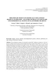
18 Preliminary design of seismically isolated RC highway overpasses

You also want an ePaper? Increase the reach of your titles
YUMPU automatically turns print PDFs into web optimized ePapers that Google loves.
shear stress (Mpa)<br />
shear stress<br />
(Mpa)<br />
George C. Manos, Stergios A. Mitoulis and Anastasios G. Sextos<br />
with the simultaneous application <strong>of</strong> continuously increasing shear strains and an imposed<br />
compressive stress field normal to the elastomer equal to 2.0MPa is shown in figure 7c; figure<br />
7d shows the resulting debonding <strong>of</strong> the elastomer from the steel plating at the end <strong>of</strong> this loading<br />
sequence. When no compressive field was applied, the level <strong>of</strong> shear strain reached first a<br />
maximum strain equal to 250% whereby the maximum shear stress was observed equal to<br />
1.6Mpa; then for larger shear strain amplitudes the bearing capacity degrades and the specimen<br />
reaches its debonding failure mode. The maximum shear stress, when the 2.0Mpa compressive<br />
field was applied, reached a maximum value equal to 2.4Mpa for a shear strain level equal to<br />
275%. Then for higher shear strain levels the bearing capacity degrades and the specimen<br />
reaches its debonding failure mode. From the comparison <strong>of</strong> the performance <strong>of</strong> the specimens<br />
with and without the compressive stress field (figures 7c and 7a) it can be seen that the most<br />
severe test is that without the normal compressive stress field. It corresponds to an elastomeric<br />
bearing that does not have the beneficial stabilizing effect <strong>of</strong> the compressive stress field normal<br />
to the slices <strong>of</strong> the elastomer.<br />
2.0<br />
1.5<br />
1.0<br />
0.5<br />
0.0<br />
Slice Bearing with rubber thickness 7.5mm<br />
0.2Hz strain amplitude<br />
from 15% to 95%<br />
Normal stress 0.0<br />
d=250mm diameter<br />
0.2Hz<br />
0.2Hz<br />
static1<br />
static1<br />
0.0 0.5 1.0 1.5 2.0 2.5 3.0<br />
shear strain<br />
Figure 7a. Shear stress-strain response <strong>of</strong> the sliced elastomeric<br />
specimens up to failure for strains in the region <strong>of</strong><br />
300%. (σ=0.0 Μpa)<br />
2.5<br />
2.0<br />
1.5<br />
1.0<br />
Slice Bearing 7.5mm thick d=250mm,<br />
Tensile Static, Normal Stress 2Mpa<br />
Shear Str. 2<br />
Shear Str. 3<br />
Failure - Test 100tn<br />
Figure 7b. The debonding <strong>of</strong> the elastomer from<br />
the steel plating at the end <strong>of</strong> this loading sequence.<br />
0.5<br />
0.0<br />
0.0 0.5 1.0 1.5 2.0 2.5 3.0<br />
shear strain<br />
Figure 7c. Shear stress-strain response <strong>of</strong> the sliced elastomeric<br />
specimens up to failure for strains in the region <strong>of</strong><br />
300%. (σ=2.0 Μpa)<br />
Figure 7d. Failing mode <strong>of</strong> the unit slice specimen<br />
with the presence <strong>of</strong> the compressive stress field.<br />
4.3 Tests with elastomeric bearings<br />
After completing an extensive sequence <strong>of</strong> tests with the slices <strong>of</strong> the elastomeric bearings,<br />
that tried to improve and validate the production process, another sequence <strong>of</strong> tests was conducted<br />
with elastomeric bearings <strong>of</strong> certain geometry as will be described in the following<br />
10