AIRPOT LIGHTING & SIGNS etc by CAA

You also want an ePaper? Increase the reach of your titles
YUMPU automatically turns print PDFs into web optimized ePapers that Google loves.
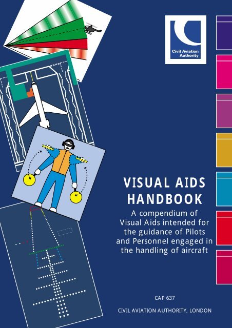
VISUAL AIDS<br />
HANDBOOK<br />
A compendium of<br />
Visual Aids intended for<br />
the guidance of Pilots<br />
and Personnel engaged in<br />
the handling of aircraft<br />
CAP 637<br />
CIVIL AVIATION AUTHORITY, LONDON
Acknowledgements<br />
VISUAL AIDS HANDBOOK<br />
This reference document was compiled <strong>by</strong> Neil Cargill, Head of Policy<br />
and Requirements, Aerodrome Standards Department, Civil Aviation<br />
Authority, Aviation House, Gatwick, RH6 0YR to whom queries and<br />
observations regarding the technical content should be addressed.<br />
Contributions from the following sources are gratefully acknowledged:<br />
Peter Cox<br />
Technical Committee, British Airline Pilots Association<br />
Anthony (Tony) Smith<br />
All Weather Operations, Defence Research Agency<br />
John Hopson<br />
Flight Operations Department, Civil Aviation Authority
VISUAL AIDS HANDBOOK<br />
A compendium of Visual Aids intended for the guidance of Pilots and<br />
Personnel engaged in the handling of aircraft.<br />
Introduction<br />
1 Visual Aids in the form of lighting, surface markings, signs and signals<br />
are provided in varying degrees of complexity at all UK<br />
licensed aerodromes and are notified in the appropriate aerodrome<br />
entry at AGA 2 and AGA 3 of the AIP.<br />
2 The minimum standards and specifications for installed visual aids<br />
other than Visual Docking Guidance Systems are laid down in<br />
CAP 168 Licensing of Aerodromes.<br />
3 The aim of this document is to explain in general terms the purpose<br />
and significance of those visual aids currently employed at<br />
licensed aerodromes in the UK. Pilots should note that as improvements<br />
to the design of aerodrome equipment take place, changes<br />
to the visual aids illustrated herein will occur from time to time.<br />
4 Readers should note that the precise legal meaning of the Signals<br />
described at Tables A to F of Section 6 herein is to be found at<br />
Section IX of the Rules of the Air Regulations (the Rules) and that<br />
where any difference between the meanings described herein and<br />
those defined in the Rules is perceived, the meaning defined in the<br />
Rules shall take precedence.
1. AERONAUTICAL GROUND <strong>LIGHTING</strong><br />
2. SURFACE MARKINGS<br />
3. <strong>SIGNS</strong><br />
4. VISUAL DOCKING GUIDANCE SYSTEMS<br />
(VDGS)<br />
5. OBSTACLE <strong>LIGHTING</strong> & MARKINGS<br />
6. AERODROME SIGNALS<br />
7. APPENDICES<br />
CONTENTS
1. AERONAUTICAL GROUND <strong>LIGHTING</strong>
1. AERONAUTICAL GROUND <strong>LIGHTING</strong><br />
1.1 General<br />
Aeronautical Ground Lighting (AGL) is the generic term used to<br />
describe the various lighting systems that are provided on an<br />
aerodrome for the guidance of pilots operating aircraft both at<br />
night and in low visibility conditions. AGL systems vary in<br />
complexity from the basic patterns found at small aerodromes<br />
in support of flying training operations, to the more advanced<br />
systems used in support of Category lll ILS procedures. The<br />
following paragraphs outline those systems that have been<br />
accepted <strong>by</strong> the <strong>CAA</strong> as meeting both aerodrome licensing and<br />
internationally agreed requirements.<br />
1.1.1 Civil Aerodromes<br />
Particulars of AGL, where available at individual aerodromes,<br />
are listed in the UK AIP (Air Pilot) at AGA 2, AGA 3 and on the<br />
appropriate Instrument Approach Charts. The AGL at licensed<br />
aerodromes is inspected at intervals <strong>by</strong> the <strong>CAA</strong>. Where a<br />
licensed aerodrome does not meet the minimum lighting<br />
requirements, the appropriate aerodrome entry at AGA 2 or<br />
AGA 3 will be annotated ‘not licensed for night use’. Lighting<br />
at unlicensed aerodromes listed in AGA 3 is neither inspected<br />
nor approved <strong>by</strong> the <strong>CAA</strong> and may be of a non-standard<br />
pattern.<br />
1.1.2 Military Aerodromes<br />
The aerodrome lighting systems installed at Military and<br />
Government aerodromes listed at AGA 3 are not inspected <strong>by</strong><br />
the <strong>CAA</strong> and may differ from those installed at civil aerodromes<br />
notably with respect to approach lighting, as shown at Figs 1b<br />
and 2. Sodium l<strong>amp</strong>s may be used to supplement approach,<br />
threshold and apron lighting.<br />
1.1.3 Colour and Intensity of Lights<br />
Unless otherwise indicated, AGL systems emit a steady white<br />
light. High intensity AGL systems that are provided in support<br />
of low visibility operations normally have facility for the<br />
independent control of brilliancy of each element of the<br />
system. The intensities are set up <strong>by</strong> ATC in order to suit local
1. AERONAUTICAL GROUND <strong>LIGHTING</strong><br />
conditions and a pilot should ask ATC to adjust them if they are<br />
found to be inappropriate.<br />
1.1.4 The performance specification of high intensity lighting is<br />
defined <strong>by</strong> the need to provide guidance <strong>by</strong> day in low visibility<br />
conditions; the highest intensity settings are normally used in<br />
these conditions. Lower intensities are normally used <strong>by</strong> night.<br />
1.1.5 Low intensity systems are provided at those aerodromes at<br />
which operations are conducted at night but not in low<br />
visibility conditions; the brilliancy of low intensity systems is not<br />
normally adjustable.<br />
1.2 Aerodrome Beacon<br />
An Aerodrome Beacon would normally be provided at those<br />
aerodromes that operate at night and where the level of<br />
background lighting, the surrounding terrain, the proximity of<br />
other aerodromes or the lack of navigation aids would make<br />
the aerodrome difficult to locate or to identify. There are two<br />
types of Aerodrome Beacon, the Identification Beacon and the<br />
Location Beacon.<br />
1.2.1 Identification Beacon<br />
An identification beacon flashing a two letter identification<br />
code in green would normally be provided at an aerodrome<br />
where a number of aerodromes in the same vicinity operate at<br />
night and confusion could arise as to identity. Military<br />
aerodromes are normally equipped with a red identification<br />
beacon.<br />
1.2.2 Location Beacon<br />
A Location Beacon would normally be provided at an<br />
aerodrome that is situated well away from other aerodromes<br />
and where no confusion could exist as to identity. The signal<br />
produced <strong>by</strong> a Location Beacon is determined <strong>by</strong> the amount of<br />
background lighting as follows:
1. AERONAUTICAL GROUND <strong>LIGHTING</strong><br />
(a)<br />
(b)<br />
White flashing light<br />
Where the aerodrome is also situated well away from<br />
areas of high background lighting, the Location Beacon<br />
would display a white flashing light.<br />
Alternately flashing green and white light<br />
Where the aerodrome is situated in an area where there is<br />
a high level of background lighting, such as in the vicinity<br />
of a city where a flashing white light would be difficult<br />
to see, the Location Beacon would display a green light<br />
flashing alternately with a white light.<br />
1.3 Approach Lighting<br />
A variety of approach lighting systems, based on the centre line<br />
and cross bar concept, are in use at aerodromes throughout the<br />
UK. These systems range from the simple low intensity centre<br />
line and cross bar – shown at Fig 1(a) and (b) – intended to<br />
serve visual runways at night only, to the more complex Calvert<br />
System comprising centreline and 5 cross bars (CL5B) – shown at<br />
Fig 3 and 4 – required for day and night use on ILS equipped<br />
runways. At some aerodromes where, because of high levels of<br />
background lighting, the approach lighting is difficult to pick<br />
out at distance, strobe lighting may be provided either in<br />
addition to the standard approach lighting or on its own as<br />
illustrated at Fig 5. Simple approach lighting systems normally<br />
commence 500m prior to the runway threshold whilst the full<br />
CL5B commences 900m prior to runway threshold. Where,<br />
because of the geography of the approach, it is not possible to<br />
install a full system, a shortened system is employed and the<br />
RVR minimum associated with the instrument procedure<br />
adjusted accordingly. Approach lighting systems in common<br />
use outside UK are illustrated at Appendix A. Except where<br />
supplemented <strong>by</strong> red side barrettes as described in para 1.3.1<br />
below, approach lighting is white in colour.
1. AERONAUTICAL GROUND <strong>LIGHTING</strong><br />
1.3.1 Supplementary Approach Lighting<br />
At those aerodromes where Category II and III ILS approaches<br />
are conducted, Supplementary Approach Lighting consisting of<br />
white centreline barrettes and two rows of red side barrettes,<br />
as shown at Fig 4, is installed in order to provide the pilot with<br />
enhanced visual cues over the last 300m of the approach.<br />
SIMPLE APPROACH AND<br />
RUNWAY <strong>LIGHTING</strong> SYSTEM<br />
APAPI<br />
HIGH INTENSITY APPROACH<br />
AND RUNWAY <strong>LIGHTING</strong><br />
INSTALLED AT SOME<br />
GOVERNMENT AND MILITARY<br />
AERODROMES<br />
Fig 1a<br />
LOW INTENSITY APPROACH<br />
<strong>LIGHTING</strong> INSTALLED AT SOME<br />
GOVERNMENT AND MILITARY<br />
AERODROMES<br />
Fig 1b Fig 2
1. AERONAUTICAL GROUND <strong>LIGHTING</strong><br />
NOTE: At certain aerodromes with displaced thresholds, the<br />
supplementary approach lighting is inset into the runway and in<br />
certain weather and ambient light conditions the centreline barrettes,<br />
at the higher intensity settings, can partially obscure the runway<br />
centreline lighting to pilots lining up for departure. Pilots experiencing<br />
problems of this nature should ask ATC to adjust the intensity or<br />
extinguish the offending system.<br />
APPROACH AND RUNWAY<br />
<strong>LIGHTING</strong> TYPICAL<br />
CAT l SYSTEM SHOWING TAKE-<br />
OFF STARTER EXTENSION AND<br />
STOPWAY <strong>LIGHTING</strong><br />
STOPWAY<br />
YELLOW<br />
CAUTION ZONE<br />
APPROACH AND RUNWAY<br />
<strong>LIGHTING</strong> TYPICAL<br />
CAT ll OR CAT lll SYSTEM<br />
RUNWAY END<br />
TOUCHDOWN<br />
ZONE<br />
COLOUR CODED<br />
CENTRELINE<br />
PAPI<br />
STARTER<br />
EXTENSION<br />
RUNWAY<br />
THRESHOLD<br />
AND WING<br />
BARS<br />
SUPPLEMENTARY<br />
APPROACH<br />
CENTRELINE<br />
AND 5 BAR<br />
Fig 3 Fig 4
1. AERONAUTICAL GROUND <strong>LIGHTING</strong><br />
SEQUENCED STROBE APPROACH<br />
<strong>LIGHTING</strong> AND RUNWAY<br />
<strong>LIGHTING</strong> AS SEEN FROM THE<br />
APPROACH<br />
RUNWAY<br />
THRESHOLD<br />
WING BARS<br />
6 6<br />
NUMBERS<br />
INDICATE<br />
ORDER OF<br />
FLASH<br />
SEQUENCE<br />
5<br />
4<br />
3<br />
2<br />
1<br />
PRE-THRESHOLD<br />
AREA NOT<br />
AVAILABLE FOR<br />
LANDING BUT<br />
AVAILABLE FOR<br />
TAKE-OFF<br />
Fig 5
1. AERONAUTICAL GROUND <strong>LIGHTING</strong><br />
1.3.2 Precision Approach Path Indicator (PAPI)<br />
1.3.2.1 This aid provides visual approach slope guidance <strong>by</strong> use of red<br />
and white light signals which are interpreted as illustrated at<br />
Fig 6. The system normally comprises a single row of 4 light<br />
units except that on those runways without ILS, a 2 unit system<br />
(APAPI) may be used. The system is normally installed on the<br />
left side of the runway as seen from the approach. However, at<br />
some aerodromes, additional units are located on the right side<br />
in order to give better roll guidance. At those aerodromes<br />
where aircraft with short take-off and landing (STOL)<br />
characteristics operate regularly, an additional separately<br />
selected PAPI, set at a steeper approach angle, may be<br />
provided. These STOL units are normally situated on the right<br />
side of the runway and operate only for STOL approaches. The<br />
PAPI signal should not be used beyond 15° either side of the<br />
runway centreline. Any additional restrictions placed on the use<br />
of a particular installation will be notified under the ‘Warnings’<br />
section of the appropriate aerodrome entry in the AIP.<br />
NOTE: Where obstacles located at the extremities of the visual signal<br />
preclude the provision of safe clearance, the appropriate aerodrome<br />
entry in AGA 2 or 3 will be annotated to that effect.<br />
1.3.2.2 The Minimum Eye Height over the Threshold (MEHT), which is<br />
notified in AGA 2 or AGA 3, is a reference value, calculated<br />
with respect to the promulgated approach angle for each PAPI.<br />
It is the lowest eye height over the runway threshold at which<br />
an onslope indication will be seen. From examination of<br />
published MEHT, it may at first sight appear that for some<br />
runways, adequate wheel clearance at the threshold is not<br />
assured for all types of aircraft likely to use those runways.<br />
However, a typical eye height achieved in practice when<br />
crossing the threshold following well established ‘on slope’<br />
approach would in fact be well above the published MEHT<br />
value.
1. AERONAUTICAL GROUND <strong>LIGHTING</strong><br />
Fig 6 TYPICAL PAPI SYSTEM<br />
A<br />
B<br />
TOO HIGH<br />
SLIGHTLY HIGH<br />
C<br />
ON CORRECT APPROACH PATH<br />
D<br />
E<br />
SLIGHTLY LOW<br />
TOO LOW
1. AERONAUTICAL GROUND <strong>LIGHTING</strong><br />
1.3.2.3 Where used together with ILS, PAPI is located so as to ensure, as<br />
far as is practicable, correlation between the two glide paths.<br />
However, such a siting is made on the assumption that the<br />
pilot’s eye level is above the ILS glide path receiver aerial, as is<br />
the case with most commercial aircraft. Pilots of aircraft in<br />
which the ILS aerial is mounted above the level of the pilot’s<br />
eye (e.g. Shorts 330) may see a PAPI indication ‘slightly low’ (see<br />
Fig 6D) when on the ILS glide path.<br />
1.4 Runway Lighting<br />
All runways licensed for night use have Edge, Threshold and End<br />
Lighting. Centreline and Touchdown Zone Lighting is provided<br />
as additional guidance in support of low visibility operations.<br />
1.4.1 Runway Edge Lighting<br />
1.4.1.1 Runway Edge Lighting is normally located along the edges of<br />
the area declared for use as the runway. However, where<br />
a paved surface is wider than the declared runway width,<br />
the lights may be located at the edge of the pavement and<br />
the declared width delineated <strong>by</strong> white edge markings as<br />
described at para 2.1.1. Edge lighting may be provided either <strong>by</strong><br />
elevated or <strong>by</strong> flush fitting l<strong>amp</strong> fixtures. At some aerodromes<br />
where elevated runway edge lights are employed, the light<br />
fixtures are located on the grass shoulder beyond the declared<br />
runway width. Portable battery operated lights or “Gooseneck”<br />
paraffin flares may be used in place of fixed l<strong>amp</strong> fittings at<br />
certain aerodromes where limited operations take place at night.<br />
1.4.1.2 Runway Edge Lighting is white except in the following<br />
instances:<br />
(a)<br />
Caution Zone Lighting<br />
On ILS equipped runways without centreline lighting,<br />
yellow edge lighting as illustrated at Fig 3, is installed on<br />
the upwind 600m or one third of the lighted runway<br />
length available, whichever is the less. The yellow ‘caution<br />
zone’ so formed gives a visual warning of the approaching<br />
runway end.
1. AERONAUTICAL GROUND <strong>LIGHTING</strong><br />
(b)<br />
(c)<br />
(d)<br />
Pre-Threshold Lighting<br />
Where a landing threshold is displaced, but the<br />
pre-threshold area is available for the take-off run, the<br />
lights between the beginning of the runway pavement<br />
and the displaced threshold show red from the approach,<br />
as illustrated at Fig 7. Pilots taking off in such a situation<br />
would see red edge lights up to the green threshold then<br />
white edge lights beyond. Where a starter extension,<br />
narrower than its associated runway is provided, blue<br />
edge lighting is normally used to mark the edges, as<br />
illustrated at Fig 7.<br />
Runway Exit Lighting<br />
One or two omni-directional blue lights may replace or<br />
supplement the edge lights in order to indicate an exit<br />
taxiway.<br />
Stopway Lighting<br />
Where stopway is provided at the end of a runway, the<br />
declared stopway is delineated <strong>by</strong> red edge and end<br />
lighting as illustrated in Fig 7 showing ONLY in the<br />
direction of landing. A stopway is provided for emergency<br />
use only and is not normally suitable for routine use.
1. AERONAUTICAL GROUND <strong>LIGHTING</strong><br />
Fig 7 RUNWAY EDGE, THRESHOLD AND EDGE <strong>LIGHTING</strong><br />
STOPWAY<br />
FOR EMERGENCY<br />
OVER-RUN USE ONLY<br />
FULL WIDTH<br />
STARTER EXTENSION<br />
NOT AVAILABLE FOR<br />
LANDINGS<br />
VIEW FROM FLIGHTDECK<br />
AIRCRAFT ON APPROACH<br />
OR LINED UP ON STARTER<br />
EXTENSION<br />
THRESHOLD LIGHTS<br />
VIEW FROM FLIGHTDECK<br />
AIRCRAFT TAXYING OR<br />
LANDING IN DIRECTION<br />
SHOWN<br />
RUNWAY EDGE<br />
<strong>LIGHTING</strong> (WHITE)<br />
VISIBLE BOTH DIRECTIONS<br />
VIEW FROM FLIGHTDECK<br />
AIRCRAFT TAXYING OR<br />
LANDING IN DIRECTION<br />
SHOWN<br />
RUNWAY END LIGHTS<br />
VIEW FROM FLIGHTDECK<br />
AIRCRAFT ON APPROACH OR<br />
LINED UP ON NARROW WIDTH<br />
STARTER EXTENSION<br />
NARROW WIDTH (BLUE)<br />
STARTER EXTENSION<br />
NOT AVAILABLE FOR<br />
LANDINGS
1. AERONAUTICAL GROUND <strong>LIGHTING</strong><br />
1.4.2 Runway Threshold and Runway End Lighting<br />
Runway threshold lighting is green and indicates the start of<br />
the available landing distance. Green threshold wing-bars are<br />
provided at certain aerodromes where there is a need to<br />
accentuate the threshold . Patterns vary from the full threshold<br />
and wingbar lighting shown at Figs 2, 3, 4 and 7 to abbreviated<br />
versions shown at Figs 1, 5 and 7. Runway end lighting is red<br />
and marks the extremity of the runway that is available for<br />
manoeuvring. Typical layouts are shown at Figs 1 – 5 and 7.<br />
Pilots must NOT land before the green threshold lighting nor<br />
continue a landing roll or taxi beyond the red runway end<br />
lights.<br />
1.4.3 Runway Centreline Lighting<br />
High intensity centreline lighting is provided in addition to<br />
edge lighting on runways equipped for low visibility<br />
operations. The centreline lighting is colour coded in order to<br />
warn a pilot of the approaching end of the runway; white<br />
centreline lighting extends from the threshold to 900m from<br />
the runway end, the following 600m is lit with alternate white<br />
and red lights, and the final 300m lit <strong>by</strong> red centreline lighting,<br />
as shown at Fig 4.<br />
1.4.4 Touchdown Zone Lighting<br />
On runways equipped for Category II and III approaches,<br />
additional lighting consisting of two rows of white barrettes,<br />
as shown at Fig 4, is installed in order to provide textural cues<br />
in the touchdown area. The additional lighting extends from<br />
the threshold either for 900m or to the midpoint of the runway<br />
whichever is the lesser distance.<br />
NOTE: The length of the Touchdown Zone lighting (normally 900m)<br />
determines the length of the Obstacle Free Zone established to protect<br />
CAT II & III approaches below DH and in the event of a baulked landing<br />
(‘go around’) after DH. A ‘go around’ initiated beyond the end of the<br />
Touchdown Zone lighting is unlikely to be contained within the<br />
Obstacle Free Zone.
1. AERONAUTICAL GROUND <strong>LIGHTING</strong><br />
1.5 Taxiway Lighting<br />
At those aerodromes equipped for low visibility operations,<br />
taxiways are equipped with green centreline lighting, otherwise<br />
blue edge lighting is provided, as shown in Fig 8. Where green<br />
centreline lighting is provided, blue taxiway edge lighting may<br />
also be installed as additional guidance on sections of taxiway<br />
that are difficult to negotiate. Where centreline lighting is<br />
employed, green taxiway centreline lighting is provided on the<br />
runway prior to an exit taxiway in order to give lead-off<br />
guidance. The edges of aprons, turning and holding areas are<br />
normally marked <strong>by</strong> blue lighting.<br />
NOTE 1: Where centreline lighting is installed on a taxiway leading<br />
onto a runway, the taxiway lighting is curved onto the near side of the<br />
runway centreline and pilots should make an appropriate allowance<br />
for any loss of Runway Declared Distance incurred in following the<br />
‘lead-on’ lighting whilst lining up for take-off.<br />
NOTE 2: Taxiway centrelines are located so as to provide safe<br />
clearance between the largest aircraft that the taxiway is designed to<br />
accommodate and fixed objects such as buildings, aircraft stands <strong>etc</strong>.,<br />
provided that the pilot of the taxiing aircraft keeps the ‘Cockpit’ of the<br />
aircraft on the centreline and that aircraft on stands are properly<br />
parked. Taxi Holding Positions are normally located so as to ensure<br />
clearance between an aircraft holding and any aircraft passing in front<br />
of the holding aircraft, provided that the holding aircraft is properly<br />
positioned behind the holding position. Clearance to the rear of any<br />
holding aircraft cannot be guaranteed. When following a taxiway<br />
route, pilots are expected to keep a good lookout, consistent with the<br />
prevailing visibility and are responsible for taking all possible measures<br />
to avoid collisions with other aircraft and vehicles.
1. AERONAUTICAL GROUND <strong>LIGHTING</strong><br />
Fig 8a TAXIWAY <strong>LIGHTING</strong><br />
APRON EDGE<br />
<strong>LIGHTING</strong><br />
CENTRELINE <strong>LIGHTING</strong><br />
TAXIWAY EDGE<br />
<strong>LIGHTING</strong><br />
STOP BAR<br />
GUARD LIGHTS<br />
COLOUR CODED<br />
CENTRELINE<br />
HIGH SPEED EXIT<br />
TAXIWAYS COLOUR<br />
CODED<br />
Fig 8b STOPBAR AND LEADING ON LIGHTS<br />
STOP BAR ON<br />
STOP BAR OFF<br />
Fig 8c RUNWAY GUARD LIGHTS<br />
Pattern A<br />
Pattern B<br />
P tt B
1. AERONAUTICAL GROUND <strong>LIGHTING</strong><br />
1.5.1 Stop Bars and Lead-on Lights<br />
Lighted Stop Bars and Lead-on Lights are provided at those<br />
aerodromes authorised for low visibility operations. A Stop Bar<br />
consists of a row of lights spaced equally across the taxiway<br />
normally at right angles to the centreline and showing red<br />
towards an approaching aircraft. At some aerodromes where,<br />
for ex<strong>amp</strong>le, a Stop Bar is located on or close to a bend in the<br />
taxiway route, additional elevated red lights are installed<br />
outboard of each taxiway edge as shown at Fig 8, in order to<br />
provide maximum advanced warning of the Stop Bar location.<br />
Stop Bars are normally installed in association with green Leadon<br />
Lights which form part of the taxiway centreline lighting<br />
beyond the Stop Bar. The Lead-on Lights are interlinked with<br />
the Stop Bar so that when the Stop Bar is ‘on’ the green<br />
centreline beyond the Stop Bar is ‘off’ and vice versa. In this<br />
way, the Stop Bar and associated Lead-on Lights act in the same<br />
sense as traffic lights and thus pilots should not taxi an aircraft<br />
across a lighted Stop Bar.<br />
1.5.2 Taxiway Guidance System<br />
At aerodromes where Category II & III operations take place or<br />
where ground movement requirements are complex, a taxiway<br />
guidance system may be installed in order to regulate traffic.<br />
The system operates <strong>by</strong> selective switching of the taxiway<br />
centreline lighting so that individual sections or routes, each<br />
terminating at a lighted Stop Bar, are illuminated in order to<br />
show the way ahead. The Stop Bar is extinguished as the next<br />
section of taxiway centreline lighting is selected.<br />
1.5.3 Runway Guard Lights<br />
On aerodromes equipped for low visibility operations, all<br />
runway entry points are “protected” <strong>by</strong> Runway Guard Lights.<br />
These are pairs of alternately flashing yellow lights, one pair<br />
located on each side of the taxiway and provide a warning of<br />
the close proximity of the runway. Where the taxiway is wider<br />
than normal, an alternative form of Runway Guard Light may be<br />
provided comprising additional pairs of flashing yellow lights<br />
inset into and str<strong>etc</strong>hing across the full width of the taxiway.<br />
The electrical circuits are so arranged that alternate lights flash
1. AERONAUTICAL GROUND <strong>LIGHTING</strong><br />
in unison. Runway Guard Lights, often referred to as “Wig<br />
Wags”, are illustrated at Fig 8 (b) and (c).<br />
1.5.4 Colour Coded Taxiway Centreline Lighting<br />
Where part of a taxiway equipped with centreline lighting lies<br />
within the ILS Sensitive Area or is sufficiently close to a runway<br />
that aircraft on that part of the taxiway would present an<br />
obstruction to aircraft landing or taking-off, that part of the<br />
taxiway will be identified <strong>by</strong> alternate green and yellow<br />
centreline lights, as shown at Fig 8. Pilots should avoid stopping<br />
with any part of their aircraft in such areas.<br />
1.5.5 Taxiway Intersection Lights<br />
At some aerodromes where multiple intersecting taxiways are<br />
not provided with selective route guidance, Taxiway Intersection<br />
Lights may be provided. These lights consist of a row of at least<br />
3 steady yellow lights disposed symmetrically about the taxiway<br />
centreline. Pilots approaching an intersection where these lights<br />
are displayed should give way to crossing traffic unless<br />
otherwise instructed <strong>by</strong> ATC.<br />
1.5.6 Reflective Taxiway Edge Markers and Centreline Studs<br />
On taxiways that are used infrequently, reflective edge markers<br />
or centreline studs may be used instead of taxiway lighting.<br />
Edge markers are blue and centreline studs are green.<br />
1.5.7 Unpaved Taxiway Routes<br />
Where taxiing is confined to specific routes on unpaved areas,<br />
the routes may either be edged with blue portable lights laid<br />
out as for normal taxiway edge lighting, or be provided with<br />
reflective taxiway edge markers. In certain circumstances, apron<br />
flood-lighting may be accepted as sufficient illumination of<br />
adjacent taxiways. On grass aerodromes where specific taxiways<br />
are not provided, the taxiway lighting requirement may be met<br />
<strong>by</strong> portable white lights marking the boundary of the<br />
manoeuvring area.
2. SURFACE MARKINGS
2. SURFACE MARKINGS<br />
2 General<br />
Surface Markings are provided on aerodromes in order to assist<br />
pilots in identifying certain locations and to provide guidance<br />
for ground movement <strong>by</strong> day. For the purposes of this<br />
document, Surface Markings have been divided into two<br />
groups namely Paved Surface Markings and Unpaved Surface<br />
Markings.<br />
2.1 Paved Surface Markings<br />
Paved Surface Markings are normally produced <strong>by</strong> the<br />
application of skid resistant paints or thermo-plastic materials<br />
directly onto the pavement. The Markings fall into three<br />
categories namely Paved Runway Markings, Paved Taxiway<br />
Markings and Paved Apron Markings, all of which are described<br />
in the following paragraphs.<br />
2.1.1 Paved Runway Markings<br />
Paved Runway Markings are white and those in use at<br />
aerodromes in UK are explained below. Illustrations of the<br />
various markings are given at Fig 9.<br />
(a)<br />
(b)<br />
Runway Designation Marking<br />
All paved runways in regular use are identified <strong>by</strong> a<br />
Runway Designation Marking. This marking consists of a<br />
two digit number indicating the magnetic heading of the<br />
runway to the nearest 10 degrees. At those aerodromes<br />
with parallel runways where the same magnetic heading<br />
applies to more than one runway, the Designation<br />
Marking will include a letter, such as ‘L’ identifying the left<br />
runway as seen from the approach, ‘C’ identifying the<br />
centre runway where there are 3 parallel runways or ‘R’<br />
for the right runway, as appropriate.<br />
Threshold, Edge and Centreline Markings<br />
All paved runways in regular use have centreline and<br />
threshold markings, the latter varying from the runway<br />
designation number alone to separate threshold and<br />
designation markings, according to the classification of
2. SURFACE MARKINGS<br />
the runway. Runway edge marking is normally provided<br />
on all ILS equipped runways and those other runways<br />
where there is insufficient contrast between the runway<br />
and its shoulders or where the declared runway width is<br />
less than the apparent width.<br />
(c)<br />
(d)<br />
Displaced Threshold Markings<br />
While threshold markings are normally located at the<br />
beginning of the paved runway surface, they may be<br />
displaced along the runway where, for ex<strong>amp</strong>le, there are<br />
obstructions on the approach or where the<br />
first portion of the pavement is not fully load bearing.<br />
Where displacement is of a temporary nature – e.g. to<br />
accommodate runway maintenance – the normal<br />
threshold markings will be obscured and the appropriate<br />
displaced threshold marking and threshold marker boards,<br />
illustrated at Fig 9, put in place in order to mark the new<br />
threshold. Whenever a threshold is displaced, the prethreshold<br />
area will be marked according to its bearing<br />
strength as illustrated at Fig 9 (d) & (e).<br />
Touchdown Zone and Aiming Point<br />
All ILS equipped runways and those other runways where<br />
the touchdown zone is insufficiently conspicuous are<br />
provided with Touchdown Zone and Aiming Point<br />
markings as shown at Fig 9 (c). These markings are<br />
intended to give added visual texture to the runway<br />
surface, particularly in conditions of poor visibility; they<br />
also indicate the optimum touchdown zone on the<br />
runway. The apparent distance between the Aiming Point<br />
marking and the Threshold Marking, as seen from the<br />
approach, is intended to aid pilots in judging their angle<br />
of approach.
2. SURFACE MARKINGS<br />
(a) Visual Runways - LDA 1200m and where Threshold requires emphasis<br />
Runway Designator<br />
Threshold Marking<br />
(c) Precision Approach Runways<br />
Aiming Point Mark<br />
Touchdown Zone Markings<br />
Edge<br />
Marking<br />
Touchdown Zone Markings<br />
(d) Permanently Displaced Threshold<br />
Pre-Threshold Markings<br />
(e) Temporarily Displaced Threshold<br />
and Pre-Threshold Markings<br />
New Threshold<br />
(i) Pre-threshold area of runway<br />
fit for movement of aircraft<br />
and available as starter<br />
extension for take-off but not<br />
available for landing<br />
(ii) Pre-threshold area of runway<br />
unfit for movement of aircraft<br />
and unsuitable as stopway<br />
(i) Pre-threshold area of runway<br />
fit for movement of aircraft<br />
and available as starter<br />
extension for take-off but not<br />
available for landing<br />
New Threshold<br />
(iii) Pre-threshold area of runway<br />
fit for use as a stopway <strong>by</strong><br />
aircraft landing in the opposite<br />
direction but not fit for normal<br />
movement of aircraft<br />
see Table C<br />
(ii) Pre-threshold area of runway<br />
unfit for movement of aircraft<br />
Fig 9 PAVED RUNWAY MARKINGS (Not to Scale)
2. SURFACE MARKINGS<br />
2.1.2 Paved Taxiway markings<br />
Paved taxiway markings are yellow in colour and consist of<br />
Centreline, Runway Taxi-Holding Position, Intermediate Taxi-<br />
Holding Position, Edge and Information markings all of which<br />
are illustrated at Fig 10 and described below. The direction in<br />
which the holding instruction implicit in the Runway Taxi-<br />
Holding Position Pattern ‘B’ and Intermediate Taxi-Holding<br />
Position markings applies, is determined <strong>by</strong> the accompanying<br />
sign described in para 3.1. i.e. – the direction from which the<br />
sign face is visible indicates the direction in which the holding<br />
requirement applies.<br />
(a)<br />
Centreline Marking<br />
Taxiway Centreline Marking consists of a single continuous<br />
yellow line marking the declared centre of the taxiway.<br />
Where a taxiway crosses a runway, the Taxiway Centreline<br />
Marking will indicate the route to be followed but the<br />
marking is interrupted as necessary in order to<br />
accommodate the runway markings. Taxiway centrelines<br />
are located so as to provide safe clearance between the<br />
largest aircraft that the taxiway is designed to<br />
accommodate and fixed objects such as buildings, aircraft<br />
stands <strong>etc</strong>., provided that the pilot of the taxiing aircraft<br />
keeps the ‘Cockpit’ of the aircraft on the centreline and<br />
that aircraft on a stand are properly parked. Taxi Holding<br />
Positions are normally located so as to ensure clearance<br />
between an aircraft holding and any aircraft passing in<br />
front of the holding aircraft, provided that the holding<br />
aircraft is properly positioned behind the holding position.<br />
Clearance to the rear of any holding aircraft cannot be<br />
guaranteed. When following a taxiway route, pilots are<br />
expected to keep a good lookout and are responsible for<br />
taking all possible measures to avoid collisions with other<br />
aircraft and vehicles.<br />
NOTE 1: At runway/taxiway intersections, where the taxiway centreline<br />
is curved onto the nearside of the runway centreline pilots should take<br />
account, where appropriate, of any loss of Runway Declared Distances<br />
incurred in following the lead-on line whilst lining up for take-off.
2. SURFACE MARKINGS<br />
NOTE 2: At major aerodromes in the UK, taxiway width is determined<br />
so as to ensure a specified minimum clearance between the taxiway<br />
edge and the main undercarriage outer wheels of the largest aircraft<br />
that the taxiway is designed to accommodate. This minimum wheel<br />
clearance is assured in turns provided that the pilot keeps the ’Cockpit’<br />
over the taxiway centreline.<br />
Runway Taxi-Holding Position marking pattern ‘A’ identifying the last<br />
holding position prior to entering runway. Marks visual/CAT I Hold<br />
where earlier CAT II/III Hold provided. Marks visual/CAT I & CAT II/III<br />
Taxi-Holding Positions where only one Taxi-Holding Position provided.<br />
Runway Taxi-Holding Position marking<br />
pattern ‘B’ identifying Category I, II OR<br />
III where a closer visual/CAT I<br />
Taxi-Holding Position is provided.<br />
Intermediate Taxi-Holding<br />
Position markings.<br />
Taxiway edge marking indicates paved<br />
shoulder of bearing strength less than Taxiway<br />
or area beyond mark not intended for aircraft use.<br />
Surface<br />
painted<br />
direction<br />
marking<br />
Surface painted<br />
location marking<br />
Taxiway<br />
centreline<br />
marking<br />
Fig 10 PAVED TAXIWAY MARKINGS (Not to Scale)
2. SURFACE MARKINGS<br />
(b)<br />
Runway Taxi-Holding Position (RTHP) Marking<br />
RTHPs are established on each taxiway leading to a<br />
runway in order to protect aircraft on take-off and<br />
landing <strong>by</strong> ensuring that other taxiing aircraft and<br />
vehicles are held well clear of the runway and, where<br />
appropriate, outside the ILS Sensitive Area. There are two<br />
styles of RTHP marking both of which are illustrated at<br />
Fig 10 and described as follows:<br />
(i)<br />
(ii)<br />
Pattern ‘A‘<br />
A Pattern ‘A‘ style RTHP marking consists of two solid<br />
and two broken lines laid across the entire width of<br />
the taxiway and normally at right angles to the<br />
taxiway centreline, the broken lines being closer to<br />
the runway (see enlargement 1 Figure 10).<br />
Pattern ‘B‘<br />
A Pattern ‘B‘ style RTHP marking, consists of a ladder<br />
style mark laid across the entire width of the taxiway<br />
and normally at right angles to the taxiway<br />
centreline (see enlargement 2 Figure 10).<br />
The last RTHP on a taxiway prior to entering the runway is<br />
always marked <strong>by</strong> a Pattern ‘A‘ RTHP marking; other<br />
RTHPs, where established on the same taxiway, are<br />
marked <strong>by</strong> a Pattern ‘B‘ style marking. RTHP markings are<br />
supported <strong>by</strong> the appropriate RTHP sign as described at<br />
para 3.1.<br />
NOTE: At those aerodromes where an ATC unit is established, pilots<br />
must not taxi beyond a Taxi-Holding Position marking towards a<br />
runway without ATC clearance. Where there is no ATC unit, the Pattern<br />
‘A‘ RTHP marking is used to indicate the position where aircraft and<br />
vehicles are required to hold whilst conceding right of way to aircraft<br />
using or on approach to the runway.<br />
(c)<br />
Intermediate Taxi-Holding Position (ITHP) Marking<br />
At those aerodromes where the taxiway layout is complex<br />
or involves multiple intersecting taxiways, ITHPs may be<br />
established in order to protect a priority taxiway route.<br />
These holding positions are marked <strong>by</strong> a single broken<br />
line laid across the entire width of the taxiway and
2. SURFACE MARKINGS<br />
normally at right angles to the taxiway centreline as<br />
illustrated in Fig 10 enlargement 3. An ITHP marking is<br />
supported <strong>by</strong> a sign as described at para 3.1.5. These<br />
markings are located so as to provide clearance from<br />
aircraft passing in front of the holding aircraft.<br />
(d)<br />
(e)<br />
Taxiway Edge Marking<br />
Edge markings as illustrated at Fig 10 enlargement 4, are<br />
used where the area beyond the taxiway edge is paved<br />
but not normally available for use <strong>by</strong> aircraft.<br />
Information Markings<br />
Information Markings, in the form of surface painted<br />
directions, may be employed where the use of a sign<br />
might cause an unacceptable obstruction. Ex<strong>amp</strong>les of<br />
Information Markings are shown at Fig 10.<br />
NOTE: Upon reaching a Taxi Holding Position identifying a taxi<br />
clearance limit, the pilot should stop the aircraft as close as possible to<br />
the Taxi-Hold Position Marking, ensuring that no part of the aircraft<br />
protrudes beyond the marking.<br />
2.1.3 Paved Apron Markings<br />
Apron markings intended for pilot use are yellow in colour.<br />
Where markings are provided for the guidance of pilots<br />
parking aircraft on stands, the position of the marking is<br />
determined on the basis that the pilot will endeavour to keep<br />
the aircraft nosewheel (see note to para 2.1.3.2) on the stand<br />
centreline. Other colours may be used for markings intended<br />
for the guidance of service vehicle drivers.<br />
2.1.3.1 Stands Provided with Visual Docking Guidance<br />
At those airports where visual docking guidance is provided, a<br />
variety of different stand layout markings are used. An ex<strong>amp</strong>le<br />
of the layout and markings used at some airports in the UK is<br />
illustrated at Figure 11(a). Visual Docking Guidance Systems<br />
(VDGS) are described at Section 4.
2. SURFACE MARKINGS<br />
Fig 11a TYPICAL STAND LAYOUT AND MARKINGS<br />
5<br />
3<br />
4<br />
7 8 7<br />
9<br />
6<br />
2<br />
10<br />
1<br />
11<br />
12 13<br />
1 Stand<br />
2 Pier<br />
3 Gate Room<br />
4 Airside Road<br />
5 Low Bridge<br />
6 Jetty<br />
7 Equipment Parking Area<br />
8 Tug Area (No Parking)<br />
9 No Parking Area<br />
10 Interstand Clearway<br />
11 Boundary between<br />
Apron and Taxiway<br />
12 Stand number and<br />
centreline<br />
13 Taxi-lane centreline
2. SURFACE MARKINGS<br />
Fig 11b SELF MANOEUVRING STAND MARKINGS<br />
TERMINAL<br />
BUILDING<br />
FULL<br />
TURN<br />
FULL<br />
TURN<br />
ALIGNMENT BARS<br />
10<br />
11<br />
APRON TAXIWAY CENTRELINE<br />
2.1.3.2 Self-manoeuvring Stand Markings<br />
The aprons of some aerodromes are provided with surface<br />
markings intended to assist pilots in taxiing their aircraft to the<br />
correct parking position without the assistance either of a<br />
marshaller or of VDGS. These markings are known as Selfmanoeuvring<br />
Stand Markings. A variety of different styles of<br />
marking are in use throughout the UK. An ex<strong>amp</strong>le of one style<br />
is at Fig 11 (b); the method of use is described below:<br />
(a)<br />
The pilot turns off the apron taxiway at the arrow which<br />
bears the allocated stand number and follows the lead-in<br />
line keeping the nosewheel on the centreline;
2. SURFACE MARKINGS<br />
(b)<br />
(c)<br />
(d)<br />
When the FULL TURN arrow is directly abeam the first<br />
pilot’s position, a turn, using the maximum nose wheel<br />
steering angle appropriate to the type of aeroplane, is<br />
initiated in the direction indicated. This turn is continued<br />
until the longitudinal axis of the aeroplane is<br />
parallel with the alignment bars seen ahead of the<br />
aeroplane as the designed parking angle is reached;<br />
When the aeroplane is parallel to the alignment bars, the<br />
turn is discontinued and the aeroplane permitted to roll<br />
forward a distance of not more than 3m in order to<br />
straighten the nose wheel. The aeroplane is then stopped;<br />
On departure, the pilot taxies off the stand in the<br />
direction indicated <strong>by</strong> the curved lead-off arrow<br />
disregarding the alignment bars.<br />
NOTE: The provision of safe clearances from other aeroplanes and<br />
fixed obstacles relies heavily on the accuracy with which the pilot<br />
follows the surface markings; turning too late, using too great a radius<br />
of turn or taxiing the aeroplane too far forward, may reduce the<br />
clearances below the safe limit. Unlike the principle used on taxiways<br />
(cockpit on centreline), when manoeuvring onto stands the pilot must<br />
keep the nosewheel on the stand centreline. If in doubt ask for<br />
assistance.<br />
2.1.3.3 Parking Spots and Parking Circles<br />
At some small aerodromes where aircraft parking space is at a<br />
premium, yellow spots or circles may be painted on the apron<br />
indicating individual aircraft parking positions. Pilots should be<br />
aware that parking on the spot or within the circle does not<br />
guarantee safe separation either from fixed obstacles or from<br />
adjacent aircraft.<br />
2.2 Unpaved Surface Markings<br />
2.2.1 Apart from the Signals described at Table ‘C‘ specified for the<br />
purpose of identifying those areas of an aerodrome that are<br />
unfit for use <strong>by</strong> aeroplanes, Unpaved Surface Markings are<br />
normally confined to unpaved runways and consist of Unpaved<br />
Runway Edge, Centreline, Threshold and End Markings.
2. SURFACE MARKINGS<br />
2.2.2 Unpaved Runway Edge and Centreline Marking<br />
The edges of unpaved runways are delineated <strong>by</strong> markers<br />
placed at regular intervals along the declared edges of the<br />
runway. Where provided, a centreline marking consists of<br />
rectangular markers inset flush with the runway surface and<br />
spaced at regular intervals along the declared runway<br />
centreline. Edge and centreline markers are normally white<br />
but may be of any single colour that best contrasts with the<br />
background.<br />
2.2.3 Unpaved Runway Threshold and End Marking<br />
The threshold and end of an unpaved runway are provided<br />
with markers of a similar type, size and colour as the edge<br />
markers. These markers are placed along the declared threshold<br />
and end of the runway and so positioned in relation to the<br />
edge markers as to form an ‘L‘ shaped mark at each corner of<br />
the runway. In addition, each threshold is marked with a two<br />
character designator showing the magnetic heading of the<br />
runway to the nearest whole ten degrees.
3. <strong>SIGNS</strong>
3. <strong>SIGNS</strong><br />
3 General<br />
The signs located on an aerodrome when used in conjunction<br />
with an aerodrome chart are intended to simplify surface<br />
movement guidance and control procedures, particularly in<br />
conditions of low visibility. Signs are divided into two<br />
categories namely Mandatory Signs and Information Signs.<br />
3.1 Mandatory Signs<br />
3.1.1 Mandatory Signs consist of Runway Taxi-Holding Position<br />
(RTHP) signs, Intermediate Taxi-Holding Position (ITHP) signs<br />
and No Entry signs and display white characters on a red<br />
background as illustrated at Fig 12 & 13. RTHP and ITHP signs<br />
are located alongside the appropriate surface marking<br />
described in para 2.1.2 and identify the holding position as well<br />
as indicate the direction in which the holding instruction<br />
applies. Pilots must not proceed beyond a Mandatory Sign<br />
without first obtaining ATC clearance to do so.<br />
3.1.2 Where there is more than one taxiway serving a runway or<br />
more than one RTHP on a taxiway, a Location Sign is normally<br />
attached to the RTHP sign in order to assist in identifying the<br />
position as illustrated at Fig 13.<br />
3.1.3 RTHP Sign for Visual and Category I Operations<br />
Where an aerodrome is equipped for operations up to and<br />
including ILS Category I approaches, an RTHP sign displaying<br />
the runway designator is located on both sides of the taxiway<br />
as illustrated at Fig 13 (a). However, at smaller aerodromes<br />
supporting only visual operations, the sign may be located on<br />
one side only (normally the left side) of the taxiway. Where<br />
there is no ATC unit, the RTHP sign identifies the position where<br />
aircraft and vehicles are required to hold whilst conceding right<br />
of way to aircraft using or on approach to the runway.
3. <strong>SIGNS</strong><br />
(a)<br />
Visual Runway Taxi-Holding Position – denotes<br />
the visual Taxi-Holding Position and also the ILS<br />
CAT I Holding Position where the Visual and CAT<br />
I Holding Positions are co-located.<br />
(i)<br />
(ii)<br />
27<br />
09–27<br />
(b) CAT I Runway Taxi-Holding Position Sign –<br />
denotes ILS CAT I Taxi-Holding Position only<br />
where a visual Taxi-Holding Position is<br />
established closer to the runway in order to<br />
expedite traffic flow.<br />
(c) CAT II Runway Taxi-Holding Position Sign –<br />
marks the ILS CAT II Taxi-Holding Position – a<br />
Visual/CAT I Taxi-Holding Position may be<br />
established closer to the runway where it is<br />
necessary to expedite traffic flow.<br />
(d) CAT III Runway Taxi-Holding Position Sign –<br />
marks the ILS CAT III Taxi-Holding Position – a<br />
CAT II Taxi-Holding Position and a Visual/CAT I<br />
Taxi-Holding Position may be established closer<br />
to the runway where it is necessary to expedite<br />
traffic flow.<br />
(e) Combined Runway Taxi-Holding Position Sign –<br />
marks the Taxi-Holding Position where the ILS –<br />
Taxi-Holding Positions are co-incident. A Visual<br />
or CAT I Taxi-Holding Position Sign may be<br />
established closer to the runway where it is<br />
necessary to expedite traffic flow.<br />
(f) Intermediate Taxi-Holding Position Sign –<br />
marks a Holding Position established to protect<br />
a priority route.<br />
(g)<br />
No Entry Sign<br />
(i)<br />
(ii)<br />
(i)<br />
(ii)<br />
(i)<br />
(ii)<br />
(i)<br />
(ii)<br />
27 CAT<br />
09–27 CAT<br />
27 CAT<br />
09–27 CAT<br />
27 CAT<br />
09–27 CAT<br />
27 CAT /<br />
27 CAT / /<br />
09–27 CAT /<br />
B2<br />
Note: 1 The signs at (i) are used where the taxiway normally serves only one runway direction.<br />
The signs at (ii) are used where the taxiway normally serves both runway directions.<br />
2 Where a runway Taxi-Holding Position serves more than one runway, the sign layout at<br />
Figure 16 is used.<br />
ments<br />
Fig 12 EXAMPLE OF MANDATORY <strong>SIGNS</strong> FOR AIRCRAFT<br />
SURFACE MOVEMENTS (Not to scale)
3. <strong>SIGNS</strong><br />
3.1.4 RTHP Sign for Category ll and lll Operations<br />
At aerodromes equipped for Category II and III ILS approaches,<br />
RTHP signs are annotated CAT II, CAT III or CAT II/III as<br />
appropriate, in the manner illustrated in Figs 12 & 13. However,<br />
because of the need to provide greater protection to Category<br />
II and III ILS systems, the RTHPs associated with these procedures<br />
are set farther back from the runway than those associated<br />
with visual or Category I operations; where this distance is such<br />
that it would hinder the expeditious flow of traffic when<br />
Category II or III procedures are not in force, a visual RTHP may<br />
be established in addition, closer to the runway, in the manner<br />
illustrated at Fig 13 (e) and (f). Exceptionally, CAT I RTHPs may<br />
be established in this manner, as illustrated at Fig 12 (b), for the<br />
same reason.<br />
3.1.5 ITHP Signs<br />
The style of sign illustrated at Fig 12 (f) is used to identify those<br />
locations where ITHPs have been established in order to protect<br />
a priority route. The signs display the taxiway designator<br />
accompanied <strong>by</strong> a number identifying the individual holding<br />
position.<br />
3.1.6 No Entry Signs<br />
Where part of an aerodrome is restricted to one way traffic or is<br />
withdrawn from use, No Entry Signs, as illustrated at Fig 12 (g),<br />
are located on both sides of the mouth of the area showing the<br />
direction from which entry is prohibited.<br />
3.2 Information Signs<br />
Information Signs consist of Location, Direction and<br />
Destination Signs; they are provided only where there is an<br />
operational need and should be used in conjunction with an<br />
aerodrome chart.
3. <strong>SIGNS</strong><br />
3.2.1 Location Signs<br />
3.2.1.1 Location Signs are used to identify taxiways and where<br />
necessary (such as at complicated intersections), runways.<br />
Taxiways are normally designated <strong>by</strong> a single letter of the<br />
alphabet, e.g. ‘A‘ for taxiway Alpha, ‘B‘ for Bravo <strong>etc</strong>. The<br />
letters ‘O‘, ‘I‘ and ‘X‘ are not used. On larger aerodromes with<br />
many taxiways, double letter designators may be used in order<br />
to identify minor taxiways adjoining a main route e.g. ‘BA‘ for a<br />
minor taxiway adjoining taxiway Bravo. Runway Location Signs<br />
use the first two numbers of the runway magnetic heading.<br />
3.2.1.2 A Location Sign consists of the characters identifying the<br />
runway or taxiway in yellow lettering on a black background<br />
surrounded <strong>by</strong> a yellow border, as illustrated in Fig 14 (a) and<br />
(b). Where there is a need to identify a specific position on a<br />
taxiway, a Location Sign, displaying the taxiway designator<br />
accompanied <strong>by</strong> an identifying number as illustrated at<br />
Fig 14 (a) (ii), is used.<br />
3.2.2 Direction and Destination Signs<br />
Direction and Destination Signs consist of a route or destination<br />
label accompanied <strong>by</strong> an arrow pointing in the appropriate<br />
direction, displayed in black characters on a yellow background<br />
as illustrated at Figure 14. Direction Signs are normally<br />
accompanied <strong>by</strong> a Location Sign and positioned on the left side<br />
of a taxiway or runway before an intersection.<br />
3.3 Typical Layout of Signs<br />
Typical layout patterns of Information and Mandatory Signs are<br />
illustrated at Figs 13, 15 and 16.
3. <strong>SIGNS</strong><br />
(a)<br />
(b)<br />
(c)<br />
(d)<br />
(e)<br />
(f)<br />
(g)<br />
Fig 13 TYPICAL RUNWAY TAXI-HOLDING POSITION <strong>SIGNS</strong><br />
AND ASSOCIATED TAXIWAY MARKINGS<br />
The diagrams illustrate typical signs associated with various Runway Taxi-holding positions on<br />
Taxiway ‘A’ leading to the threshold of Runway 27 and on Taxiway ‘D’ leading to an intermediate<br />
taxiway entrance to Runway 09-27.<br />
Note: The signs at intermediate taxiway entrances as shown at Figs (b) and (d) above are handed<br />
to show a left turn is required to reach the threshold of Rwy 09 and a right turn to reach the<br />
threshold of Rwy 27.<br />
(h)
3. <strong>SIGNS</strong><br />
(i)<br />
(a) Taxiway Designation<br />
Location Signs<br />
(a) Taxiway Location Signs<br />
(ii)<br />
(ii)<br />
Specific Location<br />
(iii)<br />
(g) (b) Taxiway Runway Ending Location Sign Sign<br />
Taxiway Ending<br />
(c) Direction Sign<br />
(b) Runway Location Sign Sign<br />
(c) Direction Sign<br />
(d) Runway Destination Sign<br />
(d) Runway Destination Sign<br />
09<br />
Note the the use use of a of hyphen a hyphen to separate to separate reciprocal designators<br />
reciprocal designators and the use of<br />
and the use of a dot to separate other designators<br />
a dot to separate other designators.<br />
(f)<br />
Inbound Destination Sign Sign<br />
(e) Destination Sign Sign to Different to Different Runways Runways<br />
STANDS<br />
1-5<br />
(g) Taxiway Ending Sign<br />
(g)<br />
(h) Runway vacated sign<br />
(Not currently used in the UK)<br />
Stand Destination Sign<br />
Fig Figure 147.16<br />
EXAMPLES Ex<strong>amp</strong>les of OF Information INFORMATION Signs (not to scale) <strong>SIGNS</strong> (Not to Scale)
3. <strong>SIGNS</strong><br />
Straight ahead Taxiway<br />
E<br />
(a) Standard 4 - Way Intersection<br />
(b) Straight ahead Taxiway has<br />
direction change greater than 25 o<br />
Straight ahead Taxiway<br />
(c) Straight ahead Taxiway has<br />
changed designation<br />
(d) Y configuration with Taxiway ‘A’<br />
changing direction<br />
E<br />
Fig 15 EXAMPLES OF TAXI GUIDANCE <strong>SIGNS</strong> AT TAXIWAY INTERSECTIONS<br />
(Not to Scale)<br />
Note:<br />
(e) Location signs indicating exit from<br />
intersection<br />
Signs are laid out as shown above, ie. from left to right in a clockwise manner. Left turn signs<br />
are on the left of the taxiway Location Sign. Right turn signs on the right, except in situations<br />
corresponding to (a) & (f) above where the double arrow direction sign is inboard of the taxiway<br />
location sign. Adjacent signs are separated <strong>by</strong> a black vertical delineator.<br />
(f)<br />
Taxiway ending sign
3. <strong>SIGNS</strong><br />
(a) Taxiway Entrance at Intersection of Two Runways<br />
Note: 1 Taxi-Holding Position<br />
signs installed at<br />
intersections such as<br />
those illustrated here are<br />
handled in the manner<br />
shown.<br />
2 Runway Location Signs<br />
for runways 31 and 13<br />
are shown in this<br />
ex<strong>amp</strong>le on the right<br />
side of the runway in<br />
order to avoid confusion.<br />
(b) Taxiway Entrance at Intersection of Two Runway Ends<br />
Fig 16 EXAMPLES OF USE OF RUNWAY LOCATION <strong>SIGNS</strong><br />
AND <strong>SIGNS</strong> AT RUNWAY TAXI-HOLDING POSITIONS<br />
SERVING MORE THAN ONE RUNWAY
4. VISUAL DOCKING GUIDANCE SYSTEMS<br />
(VDGS)
4. VISUAL DOCKING GUIDANCE SYSTEMS<br />
(VDGS)<br />
4 General<br />
Visual Docking Guidance Systems (sometimes referred to as<br />
Nose-in Docking Guidance Systems or Stand Entry Guidance<br />
Systems) provide guidance where pilot-interpreted alignment<br />
and stopping information is required for accurate parking,<br />
particularly at airbridges. Those systems currently in use in the<br />
UK are as follows:<br />
(a)<br />
(b)<br />
(c)<br />
(d)<br />
Azimuth Guidance for Nose-in Stands (AGNIS), supported<br />
<strong>by</strong> either Parallax Aircraft Parking Aid (PAPA), Side Marker<br />
Boards (SMB) or Side Marker Lines (SML)<br />
Safegate<br />
Aircraft Positioning and Information System (APIS),<br />
Aircraft Positioning System (APS) and Airpark<br />
Mirror<br />
All these systems are described in the following paragraphs and<br />
the Stands where they are in use are indicated in paragraph 26<br />
of the relevant aerodrome entry in the Air Pilot at AGA 2.<br />
NOTE 1: A pilot should not assume that a stand is safe to enter simply<br />
because the stand VDGS is active or lit. Where ground handling<br />
personnel are not present on the stand or if the pilot has any doubt<br />
about the position of any equipment on or NEAR to the stand, the<br />
aeroplane should be stopped immediately and assistance requested.<br />
NOTE 2: Except under the guidance of a marshaller, an aeroplane<br />
should not be taxied onto a VDGS equipped stand when the guidance<br />
system is switched off.<br />
NOTE 3: Ground staff should NOT activate a VDGS until a thorough<br />
inspection of the stand and its immediate surrounds has been made in<br />
order to ensure that all equipment is correctly parked in allocated areas<br />
and that the stand is safe for use <strong>by</strong> the type of aeroplane assigned.
( iii )<br />
( ii )<br />
4. VISUAL DOCKING GUIDANCE SYSTEMS<br />
(VDGS)<br />
4.1 Azimuth Guidance for Nose-in Stands (AGNIS)<br />
4.1.1 AGNIS provides Stand centreline alignment guidance and is<br />
normally used in conjunction with either PAPA, SMB or SML<br />
which provide stopping guidance separately. The system is<br />
designed for use from the left pilot position and the unit<br />
displays two closely spaced vertical light bars mounted in a box,<br />
as illustrated at Fig 17, at about flight deck height ahead of the<br />
pilot. The light bars display one of the following signals:<br />
(a)<br />
one red bar and one green bar as illustrated at Fig 17 (i) &<br />
(iii), indicating that the pilot should steer away from the<br />
red towards the green bar, or<br />
Fig 17 AGNIS
4. VISUAL DOCKING GUIDANCE SYSTEMS<br />
(VDGS)<br />
(b)<br />
two green bars, indicating correct alignment, as<br />
illustrated at Fig 17 (ii).<br />
4.1.2 AGNIS may be supported <strong>by</strong> one of the following aids:<br />
(a)<br />
PAPA<br />
This aid is positioned to the left side of the Stand<br />
centreline and provides stopping guidance <strong>by</strong> employing a<br />
black board marked with white vertical lines bearing<br />
aeroplane type identification labels and in which a<br />
horizontal slot has been cut, as illustrated at Fig 18 (i). A<br />
short distance behind the slot is a vertically-mounted<br />
white fluorescent light tube which, when aligned with the<br />
required aeroplane type line, indicates the stop-point, as<br />
shown at Fig 18 (ii). An alternative layout is illustrated at<br />
Fig 18 (iii) where the board is provided without a slot and<br />
the tube is mounted in front of it; the method of use is<br />
identical.<br />
(i)( i ) (ii)( )<br />
B747<br />
Fig 18 PAPA<br />
B747<br />
SLOT<br />
SLOT<br />
L1011<br />
B757<br />
FLUORESCENT TUBE<br />
WHITE LINE<br />
B747 1.11<br />
(iii)( )<br />
FLUORESCENT TUBE
4. VISUAL DOCKING GUIDANCE SYSTEMS<br />
(VDGS)<br />
(b)<br />
(c)<br />
SMB<br />
This aid is positioned to the left of the Stand and provides<br />
stopping guidance <strong>by</strong> employing a series of vertically<br />
mounted boards bearing aeroplane type identification<br />
labels. The boards are viewed against a contrasting<br />
background and as the aeroplane enters the Stand, the<br />
pilot sees the board faces as green in colour – meaning<br />
continue ahead – and the rear faces as red – indicating too<br />
far – appropriate to the aeroplane type. The stop point is<br />
abeam the appropriate board viewed end-on with neither<br />
the green face nor the red face visible to the handling<br />
pilot, as illustrated at Fig 19.<br />
SML<br />
Where the required stop-point is abeam the jetty itself, it<br />
may not be possible to employ SMB and type-labelled SML<br />
are painted inside the jetty end. The stop-point is where<br />
the appropriate SML appears to the pilot to be entirely<br />
vertical as illustrated at Fig 20.<br />
B727<br />
TU 154<br />
DC9<br />
F28<br />
B737<br />
TU 134<br />
TU134A<br />
727<br />
737<br />
Illustrates correct stop<br />
position for TU 154<br />
Fig 19 SMB<br />
Illustrates correct stop<br />
position for B727<br />
Fig 20 SML
4. VISUAL DOCKING GUIDANCE SYSTEMS<br />
(VDGS)<br />
4.2 Safegate<br />
4.2.1 Safegate is designed for use from the left pilot position and<br />
combines both alignment and stopping guidance in one display.<br />
The following elements of the display correspond to the letters<br />
illustrated at Fig 21:<br />
(a)<br />
An alphanumeric white dot matrix light element indicating,<br />
as appropriate:<br />
(i) Aeroplane Type e.g. A310<br />
(ii) STOP SHORT<br />
a<br />
(iii) TOO FAR<br />
(iv) OK<br />
h<br />
d<br />
(v) STOP<br />
g<br />
(vi) Door Number<br />
(which may alternate f<br />
with aeroplane type)<br />
e.g. DOOR 2<br />
(b) One pair of green lights –<br />
meaning gate ready for<br />
parking.<br />
c<br />
e<br />
(c)<br />
Alignment bar and aeroplane<br />
symbol – providing centreline<br />
guidance.<br />
b<br />
Fig 21<br />
(d) One pair of green reference lights – indicating the<br />
notional stop position.<br />
(e)<br />
(f)<br />
(g)<br />
(h)<br />
9 pairs of green progress lights – providing guidance on<br />
the closing rate with the notional stop position up to<br />
three metres before STOP.<br />
3 pairs of yellow progress lights – indicating three metres<br />
before STOP.<br />
Two pairs of red lights – STOP signal.<br />
Display indicating STOP; red light matrix.
4. VISUAL DOCKING GUIDANCE SYSTEMS<br />
(VDGS)<br />
4.2.2 Before entering the stand, a pilot must ensure that the<br />
following signals, as illustrated at Fig 22, are displayed:<br />
(a)<br />
(b)<br />
NOTE:<br />
The CORRECT AEROPLANE TYPE<br />
DESIGNATOR is displayed in<br />
flashing white.<br />
The bottom pair of green<br />
lights is flashing – indicating<br />
‘ready for docking.’<br />
These lights turn to steady when<br />
aeroplane enters stand.<br />
FAILURE TO DO SO MAY RESULT<br />
IN THE AEROPLANE COLLIDING<br />
WITH GROUND EQUIPMENT.<br />
Fig 22<br />
4.2.3 When the aeroplane is on the Stand centreline the green<br />
alignment bar and the yellow aeroplane symbol coincide,<br />
otherwise the pilot should steer the aeroplane in the direction<br />
indicated <strong>by</strong> the displacement of the aeroplane symbol in<br />
relation to the alignment bar, as illustrated at Fig 23.<br />
Fig 23<br />
(i)<br />
TURN LEFT<br />
(ii)<br />
ON CENTRELINE<br />
(iii)<br />
TURN RIGHT
4. VISUAL DOCKING GUIDANCE SYSTEMS<br />
(VDGS)<br />
4.2.4 The stopping guidance sequence is illustrated at Fig. 24 and<br />
described as follows:<br />
(a)<br />
The aeroplane nose-wheel activates sensors in the<br />
pavement 12m from STOP. At this stage, lights Y and Z<br />
(Fig 24 (i)) are continuously lighted while the green<br />
progress lights marked ‘X’ in Fig 24, will illuminate one<br />
pair at a time from the bottom pair upwards indicating<br />
closure with the notional stopping position (reference<br />
lights marked ‘Y’ in Fig 24) in 1m stages. The progress<br />
lights indicating the final 3m, are yellow. Fig 24 illustrates<br />
the display state with 4m to run at (i) – (the last of the<br />
green sequence) and with 3m to run at (ii) – (the first<br />
yellow pair).<br />
Fig 24<br />
1<br />
2<br />
3<br />
(Metres 4<br />
to<br />
stop)<br />
5<br />
6<br />
7<br />
8<br />
9<br />
10<br />
11<br />
12<br />
(Metres <br />
to 1<br />
stop) 2<br />
3<br />
<br />
(ii)<br />
(iii)<br />
(i)<br />
(iv)
4. VISUAL DOCKING GUIDANCE SYSTEMS<br />
(VDGS)<br />
(b)<br />
(c)<br />
When the aeroplane reaches the stop position (Fig 24 iii),<br />
the STOP signal and the adjacent red l<strong>amp</strong>s illuminate.<br />
The alignment bar and green reference lights then<br />
extinguish. OK! is displayed if the aeroplane is correctly<br />
parked and shortly afterwards the entire display will<br />
switch off.<br />
If the aeroplane has overrun the stop position, the<br />
TOO FAR signal appears as separate words flashing<br />
alternately on the top display panel as illustrated at<br />
Fig 24 (iv).<br />
(d) The STOP SHORT signal will appear on the top panel if<br />
either of the following events occur:<br />
(i) an object (e.g. a tow bar) is left on the sensors,<br />
or<br />
(ii) the aeroplane stops short of the correct stopping<br />
point.<br />
(e)<br />
During the docking procedure a STOP signal will be<br />
displayed whenever either of the following events occur:<br />
(i) The ground crew activates the emergency stop signal<br />
or<br />
(ii) The system’s self-test function detects an error in the<br />
system during the docking procedure.
4. VISUAL DOCKING GUIDANCE SYSTEMS<br />
(VDGS)<br />
4.3 Aircraft Positioning and Information System (APIS),<br />
Aircraft Positioning System (APS) and Airpark<br />
4.3.1 APIS is designed for use from the left pilot position and<br />
combines both alignment and stopping signals in one visual<br />
display mounted at flight deck height ahead of the pilot. The<br />
elements of the display as illustrated at Fig 25 are as follows:-<br />
(a)<br />
(b)<br />
(c)<br />
An alphanumeric yellow dot matrix element displayed in<br />
the upper portion of the unit indicating as appropriate,<br />
any of the signals illustrated.<br />
A yellow dot matrix progress strip element displayed on<br />
the lower left side of the unit indicating progress of the<br />
aeroplane over the last 16m of the approach to the stop<br />
position.<br />
An azimuth guidance element employing a moiré pattern.<br />
4.3.2 Prior to entering the stand the pilot must ensure that the<br />
following signals are displayed:-<br />
(a)<br />
(b)<br />
Correct aeroplane type<br />
Correct stand number<br />
FAILURE TO DO SO MAY RESULT IN THE AEROPLANE COLLIDING<br />
WITH GROUND EQUIPMENT<br />
4.3.3 The Azimuth Guidance element consists of a yellow moiré<br />
pattern signal providing directional guidance to the pilot in<br />
relation to the stand centreline as illustrated in Fig 25.
4. VISUAL DOCKING GUIDANCE SYSTEMS<br />
(VDGS)<br />
(a)<br />
INCOMING<br />
FLIGHT<br />
NUMBER<br />
(b)<br />
STAND<br />
READY<br />
FOR USE<br />
(c)<br />
PROCEED<br />
6m TO<br />
STOP<br />
(d) STOP<br />
(e)<br />
STOP<br />
CONFIRMED<br />
(f)<br />
STOP IS<br />
EXCEEDED<br />
Azimuth Guidance<br />
TURN RIGHT<br />
ON CENTRELINE<br />
TURN LEFT<br />
Fig 25 APIS
4. VISUAL DOCKING GUIDANCE SYSTEMS<br />
(VDGS)<br />
4.3.4 The stopping guidance sequence employs safe laser technology<br />
and is activated as follows:-<br />
(a)<br />
(b)<br />
(c)<br />
(d)<br />
(e)<br />
As the system detects an approaching aeroplane, the<br />
progress strip will decrease in length <strong>by</strong> one row at a time<br />
(representing a 0.6m stage). When the aeroplane is in the<br />
correct stop position, the progress strip is extinguished as<br />
shown in Fig 25 (d).<br />
When the aeroplane is correctly parked OK STOP<br />
is displayed,<br />
as illustrated in Fig 25 (e).<br />
If the aeroplane has over-run the correct stop position<br />
TFAR<br />
STOP will appear as illustrated at Fig 25 (f).<br />
An ESTP signal will appear if any foreign object is<br />
STOP detected ahead of the aeroplane <strong>by</strong> the system<br />
sensors or if the emergency stop procedure is activated <strong>by</strong><br />
ground crew.<br />
An STSH signal will appear along with the appropriate<br />
progress strip display if the aeroplane has for any reason<br />
stopped short of the correct stopping position.<br />
4.3.5 A simpler version of APIS known as Aircraft Positioning System<br />
(APS) is in use at some major airports. APS uses the same laser<br />
sensors and moiré pattern but has a limited alphanumeric<br />
display which normally displays only the aeroplane type for<br />
which the stand is prepared.<br />
4.3.6 Airpark, illustrated at Fig 26, employs 2 identical moiré pattern<br />
elements to provide both azimuth guidance onto the Stand<br />
centreline and Stop indication. The system is not used on<br />
stands employing airbridges.
4. VISUAL DOCKING GUIDANCE SYSTEMS<br />
(VDGS)<br />
Stopping position<br />
Indicator<br />
Azimuth<br />
Guidance<br />
Unit<br />
Stand<br />
Centre-line<br />
STOP<br />
TURN RIGHT<br />
SLOW DOWN<br />
ON CENTRELINE<br />
PROCEED<br />
TURN LEFT<br />
Fig 26 AIRPARK
4. VISUAL DOCKING GUIDANCE SYSTEMS<br />
(VDGS)<br />
4.4 Mirror<br />
4.4.1 The Mirror system is designed for use from the left pilot<br />
position and consists of a mirror mounted to the left of the<br />
stand centreline and facing the approaching aeroplane. The<br />
mirror is angled so that the pilot can see the reflection of the<br />
aeroplane nose wheel during the last few metres of the parking<br />
manoeuvre.<br />
4.4.2 The correct stopping position is indicated <strong>by</strong> aeroplane type<br />
symbols marked in mirror image on the apron surface. As the<br />
aeroplane approaches, the pilot is able to see a reflection in the<br />
mirror of the aeroplane nose wheel and the appropriate type<br />
symbol alongside which the aeroplane should be stopped.
5. OBSTACLE <strong>LIGHTING</strong> & MARKINGS
5. OBSTACLE <strong>LIGHTING</strong> & MARKINGS<br />
5 General<br />
Obstacles to air navigation are divided into two groups, namely<br />
Aerodrome Obstacles and En-route Obstacles. The following<br />
paragraphs outline the methods of marking and lighting<br />
obstacles in order that they may be readily identified.<br />
5.1 Aerodrome Obstacles<br />
5.1.1 All objects located within a 15km radius of an aerodrome that<br />
are considered to be obstacles to aircraft in flight or<br />
manoeuvring on the ground are normally lit at night and,<br />
where the obstacle is insufficiently conspicuous <strong>by</strong> day, marked<br />
in contrasting colours. Surface obstructions and areas of bad<br />
ground on aerodrome movement areas are marked <strong>by</strong> the use<br />
of coloured markers or flags. The methods of marking and<br />
lighting of aerodrome obstacles are illustrated at Figs 27, 28,<br />
29, and 30. Bad ground markers are illustrated at Table ‘C‘.
5. OBSTACLE <strong>LIGHTING</strong> & MARKINGS<br />
5.1.2 Lighting<br />
Fixed obstacles of 45 m or less in height, width and length are<br />
normally lit <strong>by</strong> a single steady red light placed at the highest<br />
practicable point; those obstacles of greater size are normally<br />
provided with additional red lights in order to outline the<br />
extent of the obstruction as shown in Fig 27. Surface<br />
obstructions and unserviceable parts of the movement area are<br />
normally delineated <strong>by</strong> portable red lights. Mobile obstacles<br />
such as vehicles and equipment frequently employed on the<br />
movement area normally display a yellow flashing light except<br />
that emergency service vehicles responding to an incident<br />
display flashing blue lights.<br />
Fig 27<br />
LESS THAN 45m OVERALL<br />
GREATER THAN 45m OVERALL<br />
Fig 28
5. OBSTACLE <strong>LIGHTING</strong> & MARKINGS<br />
5.1.3 Marking<br />
Where fixed obstacles are insufficiently conspicuous <strong>by</strong> day,<br />
they are normally marked either <strong>by</strong> alternating bands or <strong>by</strong> a<br />
chequered pattern of red or orange and white. Vehicles and<br />
other mobile equipment frequently employed on the<br />
movement area are normally painted yellow or alternatively<br />
may be fitted with distinctive yellow markers or flags.<br />
Unserviceable parts of the movement area are normally<br />
delineated either <strong>by</strong> marker boards painted in alternate bands<br />
of red or orange and white, or <strong>by</strong> diagonally split orange/<br />
white flags. Where practicable, an unserviceable part of the<br />
movement area would also be marked <strong>by</strong> one or more large<br />
white crosses. Methods of marking obstacles are shown at<br />
Fig 29. Bad ground markers are illustrated at Table ‘C’.<br />
Fig 29<br />
MARKING OF<br />
BUILDINGS AND<br />
STRUCTURES
5. OBSTACLE <strong>LIGHTING</strong> & MARKINGS<br />
5.2 En-route Obstacles<br />
5.2.1 Objects located beyond a 15km radius of an aerodrome are<br />
normally considered to be obstacles to aircraft in flight only if<br />
they exceed 150m in height. However, prominent objects of<br />
lesser height may also be regarded as obstacles where, for<br />
ex<strong>amp</strong>le, they are located on or adjacent to routes regularly<br />
used <strong>by</strong> helicopters.<br />
5.2.2 En-route obstacles are normally lit <strong>by</strong> steady red lights at night<br />
and high intensity flashing white lights <strong>by</strong> day. However,<br />
there are exceptions particularly in areas where environmental<br />
issues militate against the use of high intensity flashing lights.<br />
Normally a minimum of two vertical levels of lighting are<br />
provided, with additional levels according to the height of the<br />
structure. Methods of lighting En-route Obstacles are<br />
illustrated at Fig 28. In certain circumstances, complex<br />
obstacles may display high intensity flashing white lights <strong>by</strong><br />
night as well as <strong>by</strong> day, as illustrated in Fig 30.<br />
TOP LIGHT<br />
MIDDLE LIGHT<br />
BOTTOM LIGHT<br />
(MARKS LOWEST POINT OF SUSPENSION)<br />
Fig 30
6. AERODROME SIGNALS
6. AERODROME SIGNALS<br />
6 General<br />
6.1 At those aerodromes where General Aviation movements are<br />
significant, visual aids displayed in a Signals Area may be<br />
employed in order to provide information relating to the<br />
conduct of flying operations. Where provided, the Signals<br />
Area, measuring approximately 12m square and bounded <strong>by</strong> a<br />
white border, is so located on the aerodrome that it is visible<br />
from all directions of approach. The meaning of individual<br />
signals displayed within the Signals Area is described at Table A.<br />
6.2 In addition, these aerodromes may display signals, having the<br />
meaning described at Table B, suspended from a mast adjacent<br />
to the Signals Area.<br />
6.3 The Signals and Markings illustrated at Table C may be used at<br />
any aerodrome whether or not a Signals Area is displayed.<br />
6.4 Light Signals and Pyrotechnic Signals may also be used to<br />
convey instructions to pilots and ground staff and have the<br />
meanings described at Table D.<br />
6.5 The meaning of Aircraft Marshalling Signals prescribed <strong>by</strong> the<br />
Rules of the Air Regulations is described at Table E. Whilst<br />
Table F describes the meaning of signals made <strong>by</strong> a pilot<br />
to a marshaller.<br />
6.6 Other Marshalling Signals in common use but not prescribed <strong>by</strong><br />
the Rules of the Air Regulations are illustrated at Tables G and H.<br />
6.7 Where signals are applicable only to helicopter operations, they<br />
are marked <strong>by</strong> the symbol.
6. AERODROME SIGNALS<br />
Table A – Meaning of Signals Displayed in the Signals Area<br />
(Reference Section IX Rules of the Air Regulations)<br />
A white landing T signifies that<br />
aeroplanes and gliders taking-off or<br />
landing shall do so in a direction<br />
parallel with the shaft of the T and<br />
towards the cross arm, unless<br />
otherwise authorised <strong>by</strong> the<br />
appropriate ATC unit.<br />
A white disc displayed alongside the<br />
cross arm of the T in line with the<br />
shaft of the T signifies that the<br />
direction of landing and take-off do<br />
not necessarily coincide.<br />
A red and yellow striped arrow<br />
placed along the whole of two<br />
adjacent sides of the signals area<br />
and pointing in a clockwise<br />
direction signifies that a right hand<br />
circuit is in force.<br />
A red panel square with a yellow<br />
diagonal stripe signifies that the state<br />
of the manoeuvring area is poor and<br />
pilots must exercise special care when<br />
landing.
6. AERODROME SIGNALS<br />
Table A – Meaning of Signals<br />
Displayed in the Signals Area<br />
A red panel square with yellow stripes along<br />
each diagonal signifies that the aerodrome is<br />
unsafe for the movement of aircraft and that<br />
landing is prohibited.<br />
A white dumb-bell signifies that movements<br />
of aeroplanes and gliders on the ground shall<br />
be confined to paved, metalled or similar<br />
hard surfaces.<br />
A black strip across each disc of the white<br />
dumb-bell at right angles to its shaft signifies<br />
that aeroplanes and gliders taking-off or<br />
landing shall do so on a runway but that<br />
movement on the ground is not confined to<br />
paved, metalled or similar hard surfaces.<br />
A red letter L displayed on the dumb-bell<br />
signifies that light aircraft are permitted to<br />
take-off and land either on a runway or on<br />
the area on the aerodrome designated <strong>by</strong> a<br />
large white letter L.<br />
A white double cross signifies that glider<br />
flying is in progress.<br />
A white letter H signifies that helicopters<br />
shall take-off and land within the area<br />
designated <strong>by</strong> a large white letter H.
6. AERODROME SIGNALS<br />
Table B – Meaning of Signals Displayed on Signals Mast<br />
(Reference Section IX Rules of the Air Regulations)<br />
Description & Meaning<br />
A black ball suspended from a mast signifies that<br />
the directions of take-off and landing are not<br />
necessarily the same.<br />
Two red balls disposed one above the other, and<br />
suspended from a mast, signify that glider flying is<br />
in progress at the aerodrome.<br />
A rectangular green flag flown from a mast<br />
indicates that a right hand circuit is in force.
6. AERODROME SIGNALS<br />
Table C – Meaning of Signals Displayed on the Aerodrome<br />
(Reference Section IX Rules of the Air Regulations)<br />
Signal/Marking<br />
Location<br />
On the landing area.<br />
Description & Meaning<br />
A white letter H indicates<br />
an area reserved for<br />
take-off and landing of<br />
helicopters.<br />
On the landing area.<br />
A double white cross<br />
indicates an area reserved<br />
for the take-off and<br />
landing of gliders.<br />
c<br />
Aerodrome<br />
administrative building/<br />
control tower/<br />
flight plan office.<br />
A black letter ‘C’ on a<br />
yellow background means<br />
pilots of visiting aircraft<br />
should report here.<br />
At intervals along the<br />
boundary of an<br />
aerodrome.<br />
Orange and white striped<br />
markers are used to<br />
delineate the boundary<br />
where it is insufficiently<br />
conspicuous.<br />
Normally located on<br />
the control tower<br />
building or, in the case<br />
of a flag, flying from<br />
the mast described in<br />
Table B.<br />
A panel or flag consisting<br />
of red and yellow squares<br />
indicates that aircraft may<br />
taxi only in accordance<br />
with ATC instructions.
6. AERODROME SIGNALS<br />
Table C – Meaning of Signals Displayed on the Aerodrome<br />
Signal/Marking<br />
Location<br />
On the landing area<br />
On a selected part of<br />
the aerodrome.<br />
Description & Meaning<br />
A large white letter L<br />
indicates an area<br />
normally of grass<br />
reserved for landing<br />
and take-off of light<br />
aircraft<br />
A yellow marker in the<br />
shape of a St. George’s<br />
cross indicates an area<br />
reserved for the<br />
dropping of tow ropes<br />
or similar articles<br />
12<br />
On a portion of a<br />
runway.<br />
On a portion of a<br />
taxiway.<br />
Normally located on<br />
the control tower<br />
building<br />
A white mark in the<br />
shape of an elongated<br />
St. Andrew’s cross<br />
indicates that that<br />
portion of the runway<br />
up to the next standard<br />
marking is unfit for use<br />
<strong>by</strong> aircraft.<br />
A yellow mark in the<br />
shape of a St. Andrew’s<br />
cross indicates that that<br />
portion of the taxiway<br />
up to the next standard<br />
marking is unfit for use<br />
<strong>by</strong> aircraft.<br />
A black two figure<br />
designator against a<br />
yellow background<br />
indicates the runway in<br />
use / direction of takeoff<br />
and landing.
6. AERODROME SIGNALS<br />
Table C – Meaning of Signals Displayed on the Aerodrome<br />
Signal/Marking<br />
Location<br />
Along the boundary of<br />
the designated area.<br />
Description & Meaning<br />
Along the boundary of<br />
the designated area.<br />
Orange and white<br />
markers or flags<br />
delineate an area of<br />
the surface considered<br />
to be unfit for use <strong>by</strong><br />
aircraft.<br />
Along the boundary of<br />
the designated area.<br />
At displaced threshold<br />
on both sides of<br />
runway.<br />
Black and white<br />
triangular box<br />
section marking<br />
displaced threshold.<br />
Adjacent to the landing<br />
area and visible from<br />
each runway threshold<br />
and all directions of<br />
approach.<br />
Sometimes lit at night.<br />
Orange (or other<br />
conspicuous colour)<br />
wind sleeve indicates<br />
wind direction and<br />
speed.
6. AERODROME SIGNALS<br />
Table D – Meaning of Light and Pyrotechnic Signals<br />
(Reference Section IX Rules of the Air Regulations)<br />
Signal<br />
Steady red light to<br />
aircraft or vehicle as<br />
indicated. Red flare<br />
from tower or<br />
aircraft.<br />
Signal<br />
Flashing red light to<br />
aircraft or vehicle.<br />
Meaning<br />
Do not land. Give way<br />
continue circling.<br />
Immediate assistance<br />
required.<br />
Stop.<br />
Meaning<br />
Do not land;<br />
aerodrome closed.<br />
Move clear of landing<br />
area.<br />
Signal<br />
Flashing green light to<br />
aircraft or vehicle.<br />
Meaning<br />
return to aerodrome<br />
await landing<br />
clearance.<br />
Cleared to taxi/move<br />
on the manoeuvring<br />
area.<br />
Meaning<br />
Cleared to land.<br />
Signal<br />
Steady green light<br />
to aircraft.<br />
Cleared to take-off.
6. AERODROME SIGNALS<br />
Table D – Meaning of Light and Pyrotechnic Signals<br />
Signal<br />
Steady or flashing<br />
green or green flare<br />
from aircraft.<br />
Meaning<br />
By Night – may I land.<br />
By Day – may I land in<br />
a direction different<br />
from that indicated.<br />
Signal<br />
White flashes to<br />
aircraft or vehicle.<br />
Meaning<br />
Land here on receipt of<br />
steady green and await<br />
further instructions.<br />
Return to starting<br />
point on the<br />
aerodrome.<br />
Signal<br />
White flare from<br />
aircraft or irregular<br />
switching of navigation<br />
or landing lights.<br />
Meaning<br />
I am compelled to<br />
land.
6. AERODROME SIGNALS<br />
Table E – Meaning of Marshalling Signals<br />
(Reference Section IX Rules of the Air Regulations)<br />
(a) Right or left arm<br />
down, the other arm<br />
moved across the body<br />
and extended to<br />
indicate position of the<br />
other marshaller.<br />
Meaning Proceed<br />
under guidance of<br />
another marshaller.<br />
(b) Arms repeatedly<br />
moved upward and<br />
backward, beckoning<br />
onward.<br />
Meaning Move ahead.<br />
(c) Right arm down, left<br />
arm repeatedly moved<br />
upward and backward.<br />
The speed of arm<br />
movement indicates the<br />
rate of turn.<br />
Meaning Open up<br />
starboard engine(s) or<br />
turn to port.
6. AERODROME SIGNALS<br />
Table E – Meaning of Marshalling Signals<br />
(d) Left arm down, the<br />
right arm repeatedly<br />
moved upward and<br />
backward. The speed<br />
indicates the rate of<br />
turn.<br />
Meaning Open up port<br />
engine(s) or turn to<br />
starboard.<br />
(e) Arms repeatedly<br />
crossed above the head.<br />
The speed of arm<br />
movement indicates the<br />
urgency of the stop.<br />
Meaning Stop.<br />
(f) A circular motion of<br />
the right hand at head<br />
level, with the left arm<br />
pointing to the<br />
appropriate engine.<br />
Meaning Start engine.<br />
See also (w)<br />
(g) Arms extended, the<br />
palms facing inwards,<br />
then swung from the<br />
extended position<br />
inwards.<br />
Meaning Chocks<br />
inserted.
6. AERODROME SIGNALS<br />
Table E – Meaning of Marshalling Signals<br />
(h) Arms down, the<br />
palms facing outwards,<br />
then swung outwards.<br />
Meaning Chocks away.<br />
(j) Either arm and hand<br />
placed level with the<br />
chest, then moved<br />
laterally with the palm<br />
downwards.<br />
Meaning Cut all<br />
engines.<br />
(k) Arms placed down,<br />
with the palms towards<br />
the ground, then<br />
moved up and down<br />
several times.<br />
Meaning Slow down.
6. AERODROME SIGNALS<br />
Table E – Meaning of Marshalling Signals<br />
(l) Arms placed down,<br />
with palms towards the<br />
ground, then either arm<br />
moved up and down<br />
several times.<br />
Meaning Slow down<br />
engine(s) on side<br />
indicated <strong>by</strong> moving<br />
arm.<br />
(m) Arms placed above<br />
the head in a vertical<br />
positon.<br />
Meaning This bay.<br />
(n) The right arm raised<br />
at the elbow, with the<br />
palm facing forward.<br />
Meaning All clear:<br />
Marshalling finished.<br />
(o) Arms placed<br />
horizontally sideways.<br />
Meaning Hover.
6. AERODROME SIGNALS<br />
Table E – Meaning of Marshalling Signals<br />
(p) Arms placed down<br />
and crossed in front of<br />
the body.<br />
Meaning Land.<br />
(q) Arms placed<br />
horizontally sideways<br />
with the palms up<br />
beckoning upwards.<br />
The speed of arm<br />
movement indicates the<br />
rate of ascent.<br />
Meaning Move<br />
upwards.<br />
(r) Arms placed<br />
horizontally sideways<br />
with the palms towards<br />
the ground beckoning<br />
downwards. The speed<br />
of arm movement<br />
indicates the rate of<br />
descent.<br />
Meaning Move<br />
downwards.
6. AERODROME SIGNALS<br />
Table E – Meaning of Marshalling Signals<br />
(s) Either arm placed<br />
horizontally sideways,<br />
then the other arm<br />
moved in front of the<br />
body to that side, in the<br />
direction of the<br />
required movement;<br />
repeated several times.<br />
Meaning Move<br />
horizontally in the<br />
direction indicated.<br />
(t) Arms placed down,<br />
the palms facing<br />
forward, then<br />
repeatedly swept up<br />
and down to shoulder<br />
level.<br />
Meaning Move back.
6. AERODROME SIGNALS<br />
Table E – Meaning of Marshalling Signals<br />
(u) Left arm extended<br />
horizontally forward,<br />
then right arm making a<br />
horizontal slicing<br />
movement below left<br />
arm.<br />
Meaning Release load.<br />
Signal not<br />
used at night<br />
(v) Raise arm with fist<br />
clenched, horizontally in<br />
front of body, then<br />
extend fingers.<br />
Meaning Release<br />
brakes.<br />
See also Table G (f)<br />
Signal not<br />
used at night<br />
Raise arm and hand,<br />
with fingers extended,<br />
horizontally in front of<br />
body, then clench fist.<br />
Meaning Engage<br />
brakes.<br />
See also Table G (f)<br />
Signal not<br />
used at night<br />
(w) Left hand over head<br />
with the number of<br />
fingers extended, to<br />
indicate the number of<br />
the engine to be<br />
started, (see para (e)<br />
Table F) and circular<br />
motion of right hand at<br />
head level.<br />
Meaning Start<br />
engine(s).
6. AERODROME SIGNALS<br />
Table E – Meaning of Marshalling Signals<br />
(x) Point left arm<br />
down, move right arm<br />
down from overhead,<br />
vertical position to<br />
horizontal forward<br />
position, repeating<br />
right arm movement.<br />
Meaning Back aircraft<br />
tail to starboard.<br />
Point right arm down,<br />
move left arm down<br />
from overhead, vertical<br />
position to horizontal<br />
forward position,<br />
repeating left arm<br />
movement.<br />
Meaning Back aircraft<br />
tail to port.
6. AERODROME SIGNALS<br />
Table F – Meaning of Signals made <strong>by</strong> Pilot to Marshaller<br />
(Reference Section IX Rules of the Air Regulations)<br />
(a) Raise arm and hand with<br />
fingers extended horizontally<br />
in front of face, then clench<br />
fist.<br />
Meaning Brakes engaged.<br />
(b) Raise arm with fist<br />
clenched horizontally in<br />
front of face, then extend<br />
fingers.<br />
Meaning Brakes released.<br />
(c) Arms extended palms<br />
facing outwards, move hands<br />
inwards to cross in front of<br />
face.<br />
Meaning Insert chocks.<br />
(d) Hands crossed in front of<br />
face, palms facing outwards,<br />
move arms outwards.<br />
Meaning Remove chocks.<br />
(e) Raise the number of fingers on one hand indicating the number of the engine<br />
to be started. For this purpose the aircraft engines shall be numbered as follows,<br />
No. 1 engine shall be the port outer engine, No. 2, the port inner engine, No. 3,<br />
the starboard inner engine and No. 4, the starboard outer engine.<br />
Meaning Ready to start engine indicated.
6. AERODROME SIGNALS<br />
Table G – Other Marshalling Signals in Common Use<br />
(Not prescribed <strong>by</strong> the Rules of the Air Regulations)<br />
(a) One arm horizontal<br />
in front of the body at<br />
shoulder level hand<br />
outstr<strong>etc</strong>hed with palm<br />
facing downwards.<br />
Other arm, fist clenched,<br />
brought up to form a ‘T’.<br />
Meaning Ground power<br />
connected/request<br />
permission to connect<br />
ground power.<br />
(b) One arm horizontal in<br />
front of the body at shoulder<br />
level hand outstr<strong>etc</strong>hed with<br />
palm facing downwards.<br />
Other arm, fist clenched,<br />
held vertical to form a ‘T’.<br />
Leaving the horizontal arm<br />
in place, return the other<br />
arm smartly to the side of<br />
the body.<br />
Meaning Ground power<br />
disconnected/request<br />
permission to disconnect<br />
ground power.<br />
(c) Circular motion in<br />
the horizontal plane<br />
with the right hand<br />
above the head.<br />
Meaning Start rotors.
6. AERODROME SIGNALS<br />
Table G – Other Marshalling Signals in Common Use<br />
(d) Right arm extended<br />
horizontally sideways in<br />
direction of movement<br />
and other arm swung<br />
over the head in same<br />
direction, in a repeating<br />
movement.<br />
Meaning Move to left.<br />
(e) Left arm extended<br />
horizontally sideways in<br />
direction of movement<br />
and other arm swung<br />
over the head in same<br />
direction, in a repeating<br />
movement.<br />
Meaning Move to right.<br />
(f) ‘On’ Day: Arms above<br />
head, open palms and<br />
fingers raised with palms<br />
towards aircraft, then fist<br />
closed.<br />
‘On’ Night: Arms above<br />
head then wands crossed.<br />
‘Off’ Day: Reverse of the<br />
above.<br />
‘Off’ Night: Crossed wands<br />
then uncrossed.<br />
Meaning Brakes on/off.<br />
See also Table E (v)
6. AERODROME SIGNALS<br />
Table G – Other Marshalling Signals in Common Use<br />
(g) Make rapid<br />
horizontal figure-ofeight<br />
motion at waist<br />
level with either arm,<br />
pointing at source of<br />
fire with the other.<br />
Meaning Fire.<br />
(h) Waving of arms<br />
over head.<br />
Meaning Wave off.<br />
(j) Left hand raised<br />
vertically overhead, palm<br />
towards aircraft. The<br />
other hand indicates to<br />
personnel concerned and<br />
gestures towards aircraft.<br />
Meaning Personnel<br />
approach the aircraft/<br />
request permission for<br />
personnel to approach<br />
aircraft.
6. AERODROME SIGNALS<br />
Table G – Other Marshalling Signals in Common Use<br />
(k) Hands above head, left fist<br />
partially clenched, right hand<br />
moved in direction of left<br />
hand with first two fingers<br />
extended and inserted into<br />
circle made <strong>by</strong> fingers of the<br />
left hand.<br />
See also Table G (a)<br />
Meaning Ground power<br />
connected/request permission<br />
to connect ground power.<br />
(l) Hands above head, left<br />
fist partially clenched, right<br />
hand moved away from left<br />
hand, withdrawing first two<br />
fingers from circle made<br />
from fingers of the left<br />
hand. See also Table G (b)<br />
Meaning Disconnect<br />
ground power.<br />
(m) Both hands raised<br />
to eye level, elbows<br />
flexed and palms turned<br />
towards the aircraft in a<br />
policeman’s stop.<br />
Meaning Stop.<br />
(n) Point right, rotate left.<br />
Meaning Power back<br />
aircraft tail to left.
6. AERODROME SIGNALS<br />
Table G – Other Marshalling Signals in Common Use<br />
Point left rotate right.<br />
Meaning Power back<br />
aircraft tail to right.<br />
See Table E(x)<br />
Rotate arms in rolling<br />
action.<br />
Meaning Power back<br />
straight.<br />
See Table E(x)<br />
Contact after Push-back<br />
If communication with the ground crew is required after the ground<br />
headset has been disconnected the following procedure should be<br />
employed:<br />
(a) Flight Deck to Ground Crew:<br />
Stop the aircraft. Flash the left-hand turn-off light (or taxi light) and<br />
continue flashing the light until acknowledged <strong>by</strong> the Ground Crew<br />
waving a headset;<br />
(b) Ground Crew to Flight Deck:<br />
The ground Crew will wave the headset <strong>by</strong> day and flash the<br />
marshalling signal wands at night.<br />
(c) Flight Deck to Ground Crew:<br />
Acknowledge the Ground Crew signal <strong>by</strong> flashing the same light as<br />
in (a).<br />
LANDING LIGHTS SHOULD NOT BE USED FOR THIS SIGNAL<br />
Landing and turn-off lights must not be switched on during pushback,<br />
even during daytime, as the tug driver could be dazzled to<br />
the extent that it causes temporary blindness.
6. AERODROME SIGNALS<br />
Table H – Other Signals made <strong>by</strong> Pilot to a Marshaller<br />
(Not prescribed <strong>by</strong> the Rules of the Air Regulations)<br />
(a) One arm held at face<br />
level hand outstr<strong>etc</strong>hed<br />
with palm facing<br />
downwards. The other arm,<br />
fist clenched, brought up to<br />
form a ‘T’ of forearms.<br />
Meaning Connect ground<br />
power.<br />
(b) One arm held<br />
horizontal at face level<br />
hand outstr<strong>etc</strong>hed with<br />
palm facing downwards.<br />
The other arm, fist<br />
clenched, forming a ‘T’ of<br />
forearms. Leaving the<br />
horizontal arm in place,<br />
lower the vertical arm until<br />
out of view.<br />
Meaning Remove ground<br />
power.<br />
(c) Circular motion in the<br />
horizontal plane with right<br />
hand.<br />
Meaning Starting Rotors/<br />
engines.<br />
(d) Finger of one hand on<br />
nose point with other hand<br />
in the direction the aircraft<br />
nose is to face after pushback.<br />
Meaning Push-back so that<br />
nose is facing in direction<br />
indicated.
6. AERODROME SIGNALS<br />
Table H – Other Signals made <strong>by</strong> Pilot to a Marshaller<br />
(e) Rotate arms in<br />
rolling action.<br />
Meaning Power back<br />
straight.<br />
(f) Both hands raised to<br />
eye level, elbows<br />
flexed and palms turned<br />
towards the ground<br />
crew –<br />
hands moved in pushing<br />
motion.<br />
Meaning Push back.<br />
(g) Right hand raised<br />
to eye level, elbow<br />
flexed and palms turned<br />
away from the ground<br />
crew – hand moved in<br />
beckoning motion.<br />
Meaning Clear to<br />
approach.
APPENDICES
APPENDIX A<br />
OTHER VISUAL AIDS<br />
1 Although the visual aids illustrated in Sections 1–3 of this<br />
document are employed in most ICAO States, some differences<br />
to these standards exist at major international and regional<br />
aerodromes outside the UK.<br />
2 This Appendix outlines the major differences in lighting,<br />
markings and signs commonly found.<br />
In addition the following points should be noted:–<br />
(a)<br />
(b)<br />
(c)<br />
(d)<br />
Some States do not provide PAPI on runways equipped<br />
with electronic precision approach aids.<br />
In States where lying snow and surface ice might render<br />
white runway markings difficult to interpret, yellow<br />
runway markings are used.<br />
Yellow reflective markers are used in some States to<br />
illuminate taxiway centrelines at night.<br />
The provision of runway centreline lighting in support of<br />
CAT II & III approaches is not universal.
APPENDIX A<br />
Centreline<br />
of flashing<br />
white lights<br />
3 The ALSF-2 illustrated at Fig<br />
A1, is a high intensity<br />
approach lighting system with<br />
sequenced strobe centreline<br />
used in support of CAT II &<br />
III operations. The system<br />
extends up to 900m from the<br />
threshold but can be as short<br />
as 450m. The strobes are<br />
omitted in the last 300m of<br />
the approach. The system is<br />
often installed without the<br />
sequenced strobe lighting and<br />
as such may be referred to<br />
as ICAO CAT II / III approach<br />
lighting system.<br />
Fig A1 ALSF – 2
APPENDIX A<br />
4 The ICAO Barrette Centreline<br />
Approach Lighting System<br />
illustrated at Fig A2, is a high<br />
intensity approach lighting<br />
system with sequenced strobe<br />
centreline used in support of<br />
CAT I operations. The system<br />
extends up to 900m from<br />
the threshold, the strobes<br />
being omitted in the last<br />
300m of the approach.<br />
Shorter versions are used at<br />
some airports resulting in a<br />
higher RVR minimum for the<br />
approach.<br />
Centreline<br />
of flashing<br />
white lights<br />
Fig A2 ICAO BARRETTE<br />
CENTRELINE APPROACH <strong>LIGHTING</strong><br />
SYSTEM
APPENDIX A<br />
5 MALSF illustrated at Fig A3, is<br />
a medium intensity approach<br />
lighting system incorporating<br />
3 strobe lights on the centreline<br />
prior to the crossbar. The<br />
system is often provided<br />
without the strobe lights<br />
and in such a configuration<br />
referred to as MALS. The<br />
system is intended to support<br />
non-precision and visual<br />
approaches but is often used<br />
to support CAT I operations; it<br />
extends to 480m.<br />
Fig A3 MALSF/MALS
APPENDIX A<br />
6 MALSR illustrated at Fig A4,<br />
is a medium intensity<br />
approach lighting system<br />
similar to MALS but incorporating<br />
an extended centreline<br />
of sequenced flashing<br />
white lights. The system is<br />
intended to support both<br />
precision and non-precision<br />
approaches and extends to<br />
750m from the threshold.<br />
Fig A4 MALSR
APPENDIX A<br />
7 Although PAPI is<br />
now in widespread<br />
use throughout the<br />
ICAO States, there<br />
are some countries,<br />
notably Australia,<br />
where T-VASIs are<br />
considered to be<br />
more effective.<br />
Both PAPI and<br />
T-VASI are ICAO<br />
approved equipment.<br />
ABOVE APPROACH SLOPE<br />
ON CORRECT APPROACH SLOPE<br />
Fig A5(a) T-VASIs (TVA)
APPENDIX A<br />
8 The T-VASI operates<br />
on the same principle<br />
as the PAPI in<br />
that it provides a<br />
pilot with guidance<br />
in relation to the<br />
correct approach<br />
slope. The interpretation<br />
of the<br />
T-VASI signal is<br />
illustrated at Fig A5.<br />
BELOW APPROACH SLOPE<br />
GROSS UNDERSHOOT<br />
Fig A5(b) T-VASIs (TVA)
APPENDIX A<br />
9 Although 2 and 3 Bar VASIs are no longer recognised <strong>by</strong><br />
ICAO as a suitable approach aid, they are still used at<br />
some regional airports in the newer ICAO Member States. Like<br />
PAPI and T-VASI, the 2 and 3 Bar VASIs provide<br />
approach slope guidance but are less accurate. The<br />
method of interpreting the signals is illustrated at Fig A6.<br />
All Aircraft<br />
High<br />
2 Bar VASI<br />
On Approach Slope<br />
Low<br />
Aircraft with Large<br />
Eye/Wheel Characteristics<br />
Use upper 4 units<br />
3 Bar VASI<br />
Normal Aircraft<br />
Use lower 4 units<br />
High<br />
On<br />
Approach<br />
Slope<br />
Low<br />
Fig A6 INTERPRETATION OF VASI SIGNALS
APPENDIX A<br />
10 Alternative forms<br />
of Touchdown<br />
Zone and Aiming<br />
Point Markings<br />
such as those<br />
illustrated at<br />
Fig A7 are used<br />
extensively<br />
outside the UK.<br />
APM<br />
TDZ Markings<br />
Fig A7 TOUCHDOWN<br />
ZONE (TDZ) AND<br />
AIMING POINT<br />
MARKINGS (APM)
APPENDIX A<br />
11 Where a Starter Extension does not extend to full length<br />
of available pavement, an alternative form of prethreshold<br />
marking, as illustrated in Fig A8, may be used.<br />
Fig A8<br />
ALTERNATIVE THRESHOLD<br />
MARKINGS<br />
AVAILABLE FOR<br />
TAKE-OFF BUT BUT<br />
NOT LANDING<br />
NOT LANDING<br />
START TORA TORA<br />
TAXIWAY<br />
MARKINGS
APPENDIX A<br />
12 Some States employ alternative forms of Mandatory and Information<br />
Signs. The principal differences are illustrated at Fig A9.<br />
(a)<br />
9 – 27<br />
9<br />
Single digits for runway<br />
designators lying between 010<br />
and 090.<br />
(b)<br />
15 – APCH<br />
Indicates a Taxi-holding Position on a<br />
taxiway that passes beneath the<br />
approach to a runway.<br />
(c)<br />
ILS<br />
This sign may be used in place of CAT I, CAT II or<br />
CAT III Taxi-holding Position signs.<br />
(d)<br />
A sign displaying alternate<br />
black and yellow diagonal lines<br />
may be used to indicate the<br />
end of a taxiway.<br />
(e)<br />
Black boards displaying white numerals and<br />
placed at intervals along the left side of the<br />
runway may be used to indicate the distance<br />
(in 1000’s feet) remaining to runway end.<br />
(f)<br />
B3<br />
Blue signs with white characters may<br />
be used on apron areas to provide<br />
pilot information – stand identification<br />
<strong>etc</strong>.<br />
Fig A9 ALTERNATIVE MANDATORY<br />
AND INFORMATION <strong>SIGNS</strong>
APPENDIX A<br />
13 Land and Hold Short Operations (LAHSO) involving the<br />
simultaneous use of intersecting runways (day and night) are<br />
conducted in some States notably Australia, Canada and USA.<br />
These procedures involve an aircraft being cleared to land on one<br />
runway to hold short of another on which a landing or take-off is<br />
in progress. Currently there are no internationally agreed visual<br />
aids available to support these operations although trials are<br />
underway. Fig A10 illustrates those visual aids currently in use.<br />
(a)<br />
(b)<br />
(c)<br />
Fig A10 HOLD SHORT<br />
POSITION LIGHTS<br />
(a) The Hold Short Position is marked <strong>by</strong><br />
5 flashing white lights. Pilots must not<br />
proceed beyond these lights on landing<br />
without specific ATC clearance. The<br />
lights may be on permanently whilst<br />
LAHSO are taking place and should be<br />
ignored on take-off.<br />
(b) The Hold Short Position is marked <strong>by</strong><br />
a line of red lights str<strong>etc</strong>hing across the<br />
entire width of the runway in the form<br />
of a Stop Bar. In addition a Taxi Speed<br />
Bar comprising 5 flashing white lights is<br />
located approximately 300m prior to the<br />
Hold Short Position. Pilots should plan<br />
their landing so that they are at taxi<br />
speed at or before the Taxi Speed Bar<br />
and must not cross the red Hold Short<br />
Position lights without specific ATC<br />
clearance. The lights are normally<br />
switched off for take-off.<br />
(c) The Hold Short Position is marked <strong>by</strong><br />
a row either of steady or of flashing<br />
white lights str<strong>etc</strong>hing across the entire<br />
width of the runway and supported <strong>by</strong><br />
2 elevated light fittings each side. Pilots<br />
must not proceed beyond these lights<br />
on landing without specific ATC<br />
clearance but the lights should be<br />
ignored on take-off.
APPENDIX B<br />
VISUAL AIDS PECULIAR TO HELICOPTER OPERATIONS<br />
1 At those aerodromes that accommodate helicopter operations,<br />
helicopter pilots will normally be expected to use the visual aids<br />
described in the main body of this document. However, there<br />
are some visual aids that are peculiar to helicopter operations<br />
and these are described in the following paragraphs.<br />
2 Helicopter Approach Path Indicator (HAPI)<br />
This aid provides the helicopter pilot with guidance similar to<br />
that provided <strong>by</strong> PAPI. However, the display takes a different<br />
format and the signal interpretation is illustrated at Fig B1.<br />
NOTE: All signals emanate<br />
from a single unit source<br />
Sector<br />
Above<br />
On Slope<br />
Slightly Below<br />
Below<br />
Signal<br />
Flashing Green<br />
Steady Green<br />
Steady Red<br />
Flashing Red<br />
Fig B1 HAPI signal format
APPENDIX B<br />
3 Helicopter Aiming Point Marker<br />
This marker may be found on an area designated as a<br />
helicopter arriving point at a heliport or aerodrome and is used<br />
to mark the point at which a helicopter will arrive at a low<br />
hover on completion of an approach. The marker consists of a<br />
white equilateral triangle and may be lit as illustrated at<br />
Fig B2. From this point the helicopter will normally air-taxi to<br />
the helicopter ‘Touchdown and Lift-Off Area’ (TLOF).<br />
By day<br />
By night<br />
Fig B2 Aiming point lighting
APPENDIX B<br />
4 Air Taxiway Markers<br />
Air Taxiway Markers as illustrated in Fig B3 are used to mark<br />
the route to be followed <strong>by</strong> helicopters to air taxi from the<br />
Aiming Point to the TLOF where these areas are not co-located.<br />
5 Touch Down and Lift Off Area (TLOF)<br />
Fig B3 Air taxiway marker<br />
This area is depicted <strong>by</strong> an ‘H’ within a circle (Fig B4 (a)). The<br />
size of the circle will be a function of the undercarriage<br />
dimensions of the largest helicopter type that the site is<br />
intended to accommodate. At a hospital site, a red ‘H’ is<br />
superimposed on a ‘cross’ as shown at Fig B4 (b).<br />
Fig B4a TLOF at sites other than hospitals<br />
Fig B4b TLOF at hospital site
APPENDIX B<br />
6 Final Approach and Take-Off Area (FATO)<br />
Designation Marking<br />
The performance characteristics of some helicopters require a<br />
‘runway’ (FATO) to which normal taxiways or air taxi routes<br />
may be attached. The TLOF maybe located within the FATO. A<br />
FATO with a specific orientation (i.e. to ensure obstacle slope<br />
protection) will be designated in a similar manner to a runway<br />
and is shown at Fig B5.<br />
Fig B5 Final approach and take-off area designation marking<br />
7 Elevated Helipads<br />
Most elevated helipads in the UK are unlicensed and pilots<br />
should obtain details of marking and lighting from the owner.<br />
The size of the helipad will be a function of the performance<br />
requirements of the largest helicopter that the site is intended<br />
to serve. The TLOF circle dimension is determined as described<br />
in para 5 of this Appendix. In this application the FATO (see 6<br />
above) and TLOF will be coincident.<br />
8 Offshore Helidecks<br />
Offshore helidecks will have a TLOF dimension which is a<br />
function of the largest overall dimension of the largest<br />
helicopter using the deck and the FATO and TLOF will be<br />
coincidental. The marking and lighting of offshore helidecks is<br />
outlined in CAP 437 ‘Offshore Helicopter Landing Areas’. Due to<br />
the specialist nature of helicopter operations in support of<br />
offshore oil installations, full details of the marking and<br />
lighting of individual offshore helidecks should be obtained<br />
prior to commencing operations.
© Civil Aviation Authority 1997<br />
First published January 1997<br />
Reprinted January 2000<br />
Reprinted April 2001<br />
ISBN 0 86039 599 5<br />
Printed and distributed <strong>by</strong>:<br />
Documedia<br />
37 Windsor Street, Cheltenham, Glos GL52 2DG £30.00