

SM-A210A220SIN-DB__02-011303

Create successful ePaper yourself
Turn your PDF publications into a flip-book with our unique Google optimized e-Paper software.
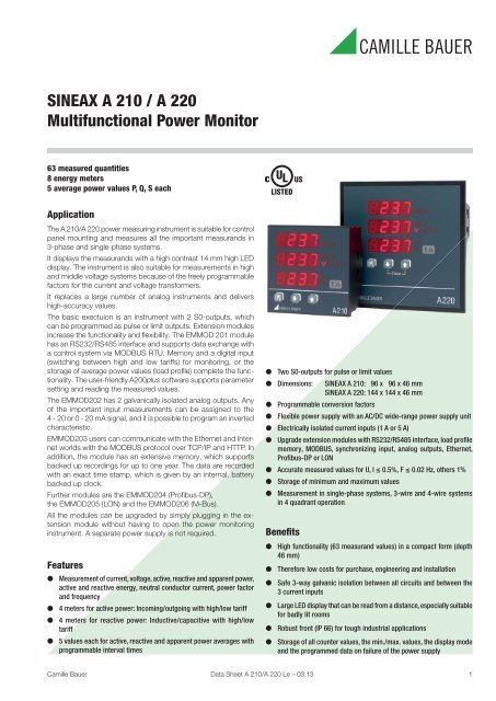
SINEAX A 210 / A 220<br />
Multifunctional Power Monitor<br />
63 measured quantities<br />
8 energy meters<br />
5 average power values P, Q, S each<br />
Application<br />
The A 210/A 220 power measuring instrument is suitable for control<br />
panel mounting and measures all the important measurands in<br />
3-phase and single-phase systems.<br />
It displays the measurands with a high contrast 14 mm high LED<br />
display. The instrument is also suitable for measurements in high<br />
and middle voltage systems because of the freely programmable<br />
factors for the current and voltage transformers.<br />
It replaces a large number of analog instruments and delivers<br />
high-accuracy values.<br />
The basic exectuion is an instrument with 2 S0-outputs, which<br />
can be programmed as pulse or limit outputs. Extension modules<br />
increase the functionality and fl exibility. The EMMOD 201 module<br />
has an RS232/RS485 interface and supports data exchange with<br />
a control system via MO<strong>DB</strong>US RTU. Memory and a digital input<br />
(switching between high and low tariffs) for monitoring, or the<br />
storage of average power values (load profi le) complete the functionality.<br />
The user-friendly A200plus software supports parameter<br />
setting and reading the measured values.<br />
The EMMOD2<strong>02</strong> has 2 galvanically isolated analog outputs. Any<br />
of the important input measurements can be assigned to the<br />
4 - 20 or 0 - 20 mA signal, and it is possible to program an inverted<br />
characteristic.<br />
EMMOD203 users can communicate with the Ethernet and Internet<br />
worlds with the MO<strong>DB</strong>US protocol over TCP/IP and HTTP. In<br />
addition, the module has an extensive memory, which supports<br />
backed up recordings for up to one year. The data are recorded<br />
with an exact time stamp, which is given by an internal, battery<br />
backed up clock.<br />
Further modules are the EMMOD204 (Profi bus-DP),<br />
the EMMOD205 (LON) and the EMMOD206 (M-Bus).<br />
All the modules can be upgraded by simply plugging in the extension<br />
module without having to open the power monitoring<br />
instrument. A separate power supply is not required.<br />
Features<br />
● Measurement of current, voltage, active, reactive and apparent power,<br />
active and reactive energy, neutral conductor current, power factor<br />
and frequency<br />
● 4 meters for active power: Incoming/outgoing with high/low tariff<br />
● 4 meters for reactive power: Inductive/capacitive with high/low<br />
tariff<br />
● 5 values each for active, reactive and apparent power averages with<br />
programmable interval times<br />
● Two S0-outputs for pulse or limit values<br />
● Dimensions: SINEAX A 210: 96 x 96 x 46 mm<br />
SINEAX A 220: 144 x 144 x 46 mm<br />
● Programmable conversion factors<br />
● Flexible power supply with an AC/DC wide-range power supply unit<br />
● Electrically isolated current inputs (1 A or 5 A)<br />
● Upgrade extension modules with RS232/RS485 interface, load profile<br />
memory, MO<strong>DB</strong>US, synchronizing input, analog outputs, Ethernet,<br />
Profibus-DP or LON<br />
● Accurate measured values for U, I ≤ 0.5%, F ≤ 0.<strong>02</strong> Hz, others 1%<br />
● Storage of minimum and maximum values<br />
● Measurement in single-phase systems, 3-wire and 4-wire systems<br />
in 4 quadrant operation<br />
Benefits<br />
● High functionality (63 measurand values) in a compact form (depth<br />
46 mm)<br />
● Therefore low costs for purchase, engineering and installation<br />
● Safe 3-way galvanic isolation between all circuits and between the<br />
3 current inputs<br />
● Large LED display that can be read from a distance, especially suitable<br />
for badly lit rooms<br />
● Robust front (IP 66) for tough industrial applications<br />
● Storage of all counter values, the min./max. values, the display mode<br />
and the programmed data on failure of the power supply<br />
Camille Bauer Data Sheet A 210/A 220 Le – 03.13 1
SINEAX A 210 / A 220<br />
Multifunctional Power Monitor<br />
Function<br />
The instrument measures the currents I1, I2, I3 and the voltages<br />
U1, U2, U3, the frequency, and the phase angles between the<br />
individual currents and voltages. All the other measurands are<br />
calculated from these. The measurements are made internally via<br />
integrated current transformers. Therefore it is possible to make<br />
direct connections without an external transformer.<br />
Each input is sampled 32 times per cycle. This allows measurements<br />
to be made including up to the 15th harmonic.<br />
The calculation of the measurands is made in accordance with<br />
DIN 40 110 part 1 and part 2, however in 4-quadrant operation.<br />
In the figures at this data sheet only SINEAX A 210 is<br />
shown. Display and operating are identical with the<br />
A 220.<br />
ind.<br />
–180 –90 0 90 180<br />
outgoing<br />
P<br />
cap.<br />
incoming<br />
ind.<br />
cap.<br />
Q<br />
outgoing<br />
<br />
L1<br />
3<br />
5<br />
9<br />
7<br />
1<br />
2<br />
L2<br />
L3<br />
N<br />
I1+<br />
I1-<br />
I2+<br />
I2-<br />
I3+<br />
I3-<br />
4<br />
μP<br />
4<br />
~<br />
~<br />
EEPROM<br />
S0 +<br />
S0 1<br />
S0 2<br />
Power<br />
supply<br />
P<br />
8<br />
10<br />
6<br />
1: Voltage inputs<br />
2: Current inputs<br />
3: Protection impedances<br />
4: Electrical insulation<br />
5: Microprocessor<br />
6: Interface for extension module<br />
7: Display of the units<br />
8: Operating keys<br />
9: Digital display<br />
10: Extension module<br />
Fig. 1. Block diagram.<br />
2 Data Sheet A 210/A 220 Le – 03.13 Camille Bauer
SINEAX A 210 / A 220<br />
Multifunctional Power Monitor<br />
Table 1: Standard versions<br />
The following transducer versions are available as standard versions. It is only necessary to quote the Order No.:<br />
Description Order Number Encoding item<br />
A 210<br />
500 V / 5 A, power supply 100 to 230 V AC/DC 149 783 210-121200<br />
500 V / 5 A, power supply 24 to 60 V AC/DC 150 300 210-121100<br />
500 V / 1 A, power supply 100 to 230 V AC/DC 152 447 210-111200<br />
Please complete the Order Code 210-1... . acc. to “Table 2: Specifi cation and ordering information” for versions<br />
with user-specifi c input ranges and/or variable sensitivity.<br />
Table 2: Specification and ordering information (see also Table 1: “Standard versions”)<br />
Description<br />
Feature<br />
SINEAX A210, Multifunctional power monitor, size 96 x 96 mm 210-<br />
SINEAX A220, Multifunctional power monitor, size 144 x 144 mm 220-<br />
Features, Selection<br />
1. Nominal voltage<br />
500 V (Ph-Ph), 290 V (Ph-N): Overload ≤20% 1<br />
2. Nominal current<br />
1 A 1<br />
5 A 2<br />
3. Nominal frequency<br />
50 / 60 Hz 1<br />
4. Power supply<br />
24...60 V AC/DC 1<br />
100...230 V AC/DC 2<br />
5. Test certificate<br />
Without test certifi cate 0<br />
Test certifi cate German<br />
D<br />
Test certifi cate Englisch<br />
E<br />
6. Built-on extension module<br />
Without 0<br />
EMMOD 201 Interface MO<strong>DB</strong>US/RTU, data logger, digital input 1<br />
EMMOD 2<strong>02</strong> 2 analog outputs 2<br />
EMMOD 203 Ethernet, real-time clock, 2 digital inputs, 2 MB data logger 3<br />
EMMOD 204 Interface Profi bus-DP 4<br />
EMMOD 205 Interface LON, digital input 5<br />
EMMOD 205 Interface LON, digital output 125 V, direct connection to<br />
summation station U160x of Gossen-Metrawatt possible"<br />
6<br />
EMMOD 206 Inteface M-Bus, digital input
SINEAX A 210 / A 220<br />
Multifunctional Power Monitor<br />
Technical data<br />
System/application<br />
Single-phase, 3-wire balanced or unbalanced, 4-wire balanced or<br />
unbalanced, 4-quadrant operation<br />
Measurements available<br />
Measured quantities Measuring path max min<br />
Voltage 1-N, 2-N, 3-N ● ●<br />
Voltage 1-2, 2-3, 3-1 ● ●<br />
Current 1, 2, 3, N ●<br />
Current I avg<br />
(bimetal -15 min/ 1, 2, 3 ●<br />
slave pointer)<br />
Active power P 1, 2, 3, ∑ ●<br />
Reactive power Q 1, 2, 3, ∑ ●<br />
Apparent power S 1, 2, 3, ∑ ●<br />
cosϕ (4-quadrant display) 1, 2, 3, ∑<br />
cosϕ inductive min. 1, 2, 3 ●<br />
cosϕ capacitive min. 1, 2, 3 ●<br />
Frequency<br />
U, I<br />
P-meter incoming/outgoing (HT/ ∑<br />
NT)<br />
Q-meter ind./cap. (HT/NT) ∑<br />
5 active power interval value ∑<br />
5 reactive power interval values ∑<br />
5 apparent power interval values ∑<br />
EN 60 529<br />
DIN 43 864<br />
DIN 40 110<br />
Protection types by case<br />
Current interface for the transmission of impulses<br />
between impulse encoder counter and<br />
tarif meter (S0 output)<br />
AC quantities<br />
IEC/EN 61326-1 Electrical equipment for measurement,<br />
IEC/EN 61326/A1 control and laboratory use, EMC requirements<br />
EN 60 688 Electrical measuring transducers for converting<br />
AC electrical variables into analogue and digital<br />
signals<br />
IEC 68-2-1/-2/-3/-6/-27<br />
resp.<br />
EN 60 068-2-1/-2/-3/-6/-27<br />
Ambient tests<br />
-1 Cold, -2 Dry heat,<br />
-3 Damp heat, -6 Vibration,<br />
-27 Shock<br />
Measuring inputs<br />
Nominal frequency:<br />
Nominal input voltage:<br />
Nominal input current:<br />
Waveform:<br />
Own consumption:<br />
50, 60 Hz<br />
Phase-phase: 500 V<br />
Phase-N: 290 V<br />
5 A or 1 A<br />
Sine<br />
Current circuit: ≤ I 2 · 0.01 Ω<br />
Voltage circuit: ≤<br />
U LN<br />
2<br />
300 kΩ<br />
Programmable values (basic unit)<br />
Trip points, pulse rate, transformer ratio, type of system, interval<br />
time for average power values.<br />
Programming can be locked with a jumper at the back of the<br />
instrument.<br />
However, the limit values can still be changed.<br />
All min. and max. values and the counter values can be reset.<br />
The resetting of the counter values can also be blocked with the<br />
above mentioned jumper.<br />
All the measurands, the selected display, the counter values and<br />
the programmed data are kept on a power failure.<br />
Factory default<br />
Brightness:<br />
(mid setting)<br />
Limit value / S01:<br />
Off<br />
Limit value / S<strong>02</strong>:<br />
Off<br />
Transformer ratio: 1 : 1<br />
Jumper:<br />
Not in the LOCK position<br />
Connecting mode: 4-wire asymmetric load<br />
Synchronizing interval: 15 min.<br />
Applicable regulations and standards<br />
IEC 1010 resp. Safety regulations for electrical measuring,<br />
EN 61 010 control and laboratory equipment<br />
Continuous overload withstand<br />
10 A at 346 V in single-phase AC system<br />
10 A at 600 V in three-phase system<br />
Short duration overload withstand<br />
Input variable<br />
Number of<br />
applications<br />
Duration of<br />
overload<br />
577 V LN 10 1 s 10 s<br />
100 A 10 1 s 100 s<br />
100 A 5 3 s 5 min.<br />
Interval between<br />
two overloads<br />
Measuring range<br />
U, I, S: ≤ 120% of nominal value<br />
P, Q: ≤ ± 120% of nominal value<br />
F: 45 to 65 Hz<br />
cosϕ: ± 1<br />
Overload indicator: oL<br />
The frequency is measured from the current or voltage. The voltage<br />
has priority.<br />
4 Data Sheet A 210/A 220 Le – 03.13 Camille Bauer
SINEAX A 210 / A 220<br />
Multifunctional Power Monitor<br />
Pulse/limit value outputs<br />
Depending on the function selected, the two digital outputs can<br />
be used either as pulse outputs for active and reactive energy or<br />
as limit signals.<br />
The outputs are passive, and are galvanically isolated from all the<br />
other circuits by opto-couplers. They are suitable to drive tariff<br />
devices (S0-standard DIN 43 864) or 24 V-relais.<br />
U ext<br />
≤ 40 V DC (OFF: leakage current ≤ 0.1 mA)<br />
I L<br />
≤ 150 mA (ON: terminal voltage ≤ 1.2 V)<br />
Display<br />
14 mm LED digital display; adjustable brightness<br />
3 digits with sign, frequency: 4 digits, energy: 8 digits<br />
Colour: red<br />
Zero value suppression<br />
PF resp. cosϕ:<br />
Display ---, if Sx < 0.2% Snenn<br />
Currents:<br />
Display 0, if Ix < 0.1% Inenn<br />
Example of the display for 4-quadrant measurements<br />
U ext<br />
20<br />
SO2<br />
21<br />
R L<br />
U<br />
t<br />
e.g. energy import<br />
SO1<br />
R L<br />
U<br />
e.g. limit value output<br />
22<br />
P<br />
P<br />
Limit value outputs:<br />
the limits can be associated with any measurand. Depending on<br />
the type of connection an OR or an AND function is possible for<br />
the following values.<br />
System Phase 1<br />
3-wire unbalanced load: U 12<br />
/U 23<br />
/U 31<br />
, I 1<br />
/I 2<br />
/I 3<br />
, I avg1<br />
/I avg2<br />
/I avg3<br />
4-wire unbalanced load: U 1<br />
/U 2<br />
/U 3<br />
, U 12<br />
/U 23<br />
/U 31<br />
, I 1<br />
/I 2<br />
/I 3<br />
,<br />
I avg1<br />
/I avg2<br />
/I avg3<br />
, P 1<br />
/P 2<br />
/P 3<br />
, Q 1<br />
/Q 2<br />
/Q 3<br />
, S 1<br />
/S 2<br />
/S 3<br />
, PF 1<br />
,/PF 2<br />
/PF 3<br />
Alarm ON: OR function of the phase measurands<br />
Alarm OFF: AND function of the phase measurands<br />
Delay time: Fixed at 1 s (cannot be modifi ed)<br />
P<br />
Phase 2 Phase 3<br />
P<br />
Pulse outputs:<br />
The reactive and active energy can be read out at the pulse outputs<br />
in the form of standard S0 pulses for the driving of electronic and<br />
electromechanical counting mechanisms.<br />
inductive<br />
capacitive<br />
incoming<br />
outgoing<br />
The pulse rate is programmable:<br />
1 … 5000 Imp./Wh … GWh resp. 1 … 5000 Imp/varh … Gvarh<br />
The duration of the pulses cannot be programmed and also cannot<br />
be changed by hardware means.<br />
Pulse duration:<br />
> 100 ms<br />
For systems with external transformers, the pulses are for the<br />
primary energy data.<br />
7-segment<br />
display<br />
top<br />
centre<br />
Units display<br />
Power supply<br />
DC, AC power pack 50 to 400 Hz<br />
100 to 230 V AC/DC ±15% or 24 to 60 V AC/DC ±15%<br />
(UL) 85 to 125 V DC<br />
Power consumption: < 3 VA (without interface module)<br />
Key for<br />
programming<br />
and display<br />
bottom<br />
P<br />
System display<br />
Up key<br />
Down key<br />
Camille Bauer Data Sheet A 210/A 220 Le – 03.13 5
SINEAX A 210 / A 220<br />
Multifunctional Power Monitor<br />
Display levels: e.g. 4-wire unbalanced load<br />
1<br />
2<br />
3<br />
4<br />
5<br />
U1<br />
U2<br />
U3<br />
I1<br />
I2<br />
I3<br />
P1<br />
P2<br />
P3<br />
Q1<br />
Q2<br />
Q3<br />
S1<br />
S2<br />
S3<br />
P<br />
a b c d e f<br />
U1 max.<br />
U2 max<br />
U3 max<br />
I1 max.<br />
I2 max<br />
I3 max<br />
U1 min.<br />
U2 min.<br />
U3 min.<br />
I1 avg<br />
I2 avg<br />
I3 avg<br />
U12<br />
U23<br />
U31<br />
P1 max<br />
P2 max.<br />
P P max.<br />
P3 max<br />
Q1 max.<br />
Q2 max.<br />
Q Q max.<br />
Q3 max<br />
S1 max.<br />
S2 max<br />
S S max.<br />
S3 max.<br />
U12 max.<br />
U23 max.<br />
U31 max.<br />
U12 min.<br />
U23 min.<br />
U31 min.<br />
I1 avgmax.<br />
I2 avgmax.<br />
IN IN max.<br />
I3 avgmax.<br />
6 PF1 PF2 PF3 PF PF minind<br />
PF mincap<br />
7 F<br />
8 EPinc HT 1 EP inc LT 2 EP out HT 1 EP out LT 2<br />
9 EQ ind HT 1 EQ ind LT 2 EQ cap HT 1 EQ cap LT 2<br />
10<br />
P<br />
Q<br />
PF<br />
P<br />
S<br />
F<br />
11 Pint0 Pint1 Pint2 Pint3 Pint4<br />
12 Qint0 Qint1 Qint2 Qint3 Qint4<br />
13 Sint0 Sint1 Sint2 Sint3 Sint4<br />
1<br />
HT = High tariff<br />
2<br />
LT = Low tariff<br />
Safety<br />
Protection class:<br />
Measuring category:<br />
Pollution degree: 2<br />
Measurement voltage: 300 V<br />
Test voltage:<br />
II (voltage inputs with protection<br />
impedances)<br />
III<br />
Between current inputs, power<br />
supply, digital outputs, terminals of<br />
the plugged-in module: 3700 V /<br />
50 Hz / 1 min.<br />
On voltage inputs:<br />
4.25 kV 1.2/50 μs<br />
Module connections: The pin rail at the back is connected<br />
to the voltage inputs via<br />
a protec-tion impedance. Only<br />
the permitted modules can be<br />
plugged-in!<br />
Enclosure protection: Front IP 66, terminals IP 20<br />
Accuracy data<br />
Reference conditions acc. to IEC 688 resp. EN 60 688<br />
Sine 50 - 60 Hz, 15 - 30°C, application group II<br />
Measurement accuracy (related to nominal value)<br />
Current, voltage ± 0.5%<br />
Power ± 1.0%<br />
Power factor ± 1.0%<br />
Energy ± 1.0%<br />
Frequency<br />
± 0.<strong>02</strong> Hz (abs.)<br />
Mechanic<br />
Dimensions A 210: 96 x 96 x 46 mm;<br />
Panel cutout<br />
92 +0.8 x 92 +0.8 mm<br />
A 220: 144 x 144 x 46 mm;<br />
Panel cutout<br />
138 +1 x 138 +1 mm<br />
Terminals:<br />
Inputs<br />
Screw terminals<br />
Wire gauge single wire:<br />
0.5 - 2.5 mm 2<br />
Wire gauge fi ne wire:<br />
0.5 - 1.5 mm 2<br />
Power supply, outputs Clamps<br />
Wire gauge single and fi ne wire:<br />
0.5 - 1.5 mm 2<br />
Housing material:<br />
Weight:<br />
Mounting:<br />
Environmental conditions<br />
Operating temperature: – 10 to + 55 °C<br />
Storage temperature: – 25 to + 70 °C<br />
Humidity relative: ≤ 75%<br />
Altitude:<br />
2000 m max.<br />
Indoor use statement<br />
ABS<br />
flammability class V-0 acc. to<br />
UL 94, self-extinguishing, nondripping,<br />
free of halogen<br />
250 g at A 210 resp.<br />
300 g at A 220<br />
For control panel mounting<br />
Inputs, outputs and power supply are electrically isolated. The<br />
current inputs are electrically isolated from each other.<br />
6 Data Sheet A 210/A 220 Le – 03.13 Camille Bauer
SINEAX A 210 / A 220<br />
Multifunctional Power Monitor<br />
Electrical connections<br />
System /<br />
application<br />
Terminals<br />
2 5 8 1 3 7 9<br />
2 5 8 1 3 7 9<br />
Measuring input, acc. to measuring mode<br />
I1<br />
U1<br />
I2<br />
U2<br />
I3<br />
U3<br />
N<br />
3-wire<br />
3 phase<br />
asymmetric<br />
load<br />
L1<br />
L2<br />
L3<br />
2 5 8 1 3 7 9<br />
L1<br />
L2<br />
L3<br />
k<br />
l<br />
K L k l<br />
2 5 8 1 3 7 9<br />
K<br />
L<br />
u<br />
u<br />
u<br />
1 2 3 4 5 6 7<br />
I1 U1 I1 I2 U2 I2 I3<br />
UL: 3~300V 5A 50/60Hz CAT III<br />
IEC: 3~500/290V 5A 50/60Hz CAT III<br />
SINEAX A210 Mat: 149783/1234567/001<br />
210-121200 Man: 10/<strong>02</strong><br />
NLBxxxx<br />
SO<br />
1 2<br />
LOCK<br />
22 21 20<br />
8<br />
U3<br />
9<br />
I3<br />
11<br />
N<br />
Camille Bauer AG<br />
Switzerland<br />
100-230V AC<br />
85-125V DC<br />
50-400Hz 3VA<br />
14 15<br />
u<br />
U<br />
L1<br />
L2<br />
L3<br />
v<br />
V<br />
2<br />
u<br />
U<br />
v<br />
V<br />
k<br />
l<br />
K L k l<br />
11 1 3<br />
K<br />
L<br />
L1<br />
L2<br />
L3<br />
x<br />
X<br />
U<br />
x<br />
X<br />
U<br />
x<br />
X<br />
U<br />
2 11 1 3<br />
k<br />
l<br />
K L k l<br />
K<br />
L<br />
k<br />
l<br />
System /<br />
application<br />
Single-phase<br />
AC system<br />
1 2 +<br />
Pulse / Limit<br />
value outputs<br />
Connecting modes<br />
L1<br />
N<br />
Jumper<br />
2 11 1 3<br />
2 11 1 3<br />
Power supply<br />
Terminals<br />
L1<br />
N<br />
2 11 1 3<br />
K<br />
k<br />
l<br />
L<br />
4-wire<br />
3 phase<br />
symmetric<br />
load<br />
I: L1<br />
L1<br />
L2<br />
L3<br />
N<br />
L1<br />
L2<br />
L3<br />
N<br />
u<br />
U<br />
2 11 1 3<br />
v<br />
V<br />
K<br />
k<br />
l<br />
L<br />
L1<br />
L2<br />
L3<br />
Connect the voltage according to the<br />
following table for current measurement<br />
in L2 or L3:<br />
Current transf. Terminals 2 11<br />
L2 1 3 L2 N<br />
L3 1 3 L3 N<br />
N<br />
K<br />
L<br />
u<br />
v<br />
2 5 8 11 1 3 4 6 7 9<br />
L1<br />
N<br />
U<br />
2 5 8 1 3<br />
V<br />
K<br />
k<br />
l<br />
L<br />
2 5 8 1 3<br />
L1<br />
L2<br />
L3<br />
N<br />
3-wire,<br />
3-phase<br />
symmetric<br />
load<br />
I: L1<br />
L1<br />
L2<br />
L3<br />
u<br />
U<br />
L1<br />
L2<br />
L3<br />
2 5 8 1 3<br />
v<br />
V<br />
u<br />
U<br />
v<br />
V<br />
K<br />
k<br />
l<br />
L<br />
L1<br />
L2<br />
L3<br />
K<br />
k<br />
l<br />
L<br />
4-wire<br />
3 phase<br />
asymmetric<br />
load<br />
L1<br />
L2<br />
L3<br />
N<br />
2 5 8 11 1 3 4 6 7 9<br />
u<br />
x<br />
u<br />
x<br />
u<br />
x<br />
K<br />
k<br />
2 5 8 11 1 3 4 6 7 9<br />
l<br />
L<br />
K<br />
k<br />
l<br />
L<br />
K<br />
k<br />
l<br />
L<br />
Connect the voltage according to the following<br />
table for current measurement in L2 or L3:<br />
L1<br />
L2<br />
L3<br />
N<br />
X<br />
U<br />
X<br />
U<br />
X<br />
U<br />
K<br />
k<br />
l<br />
L<br />
K<br />
k<br />
l<br />
L<br />
K<br />
k<br />
l<br />
L<br />
Current Terminals 2 5 8<br />
transf.<br />
L2 1 3 L2 L3 L1<br />
L3 1 3 L3 L1 L2<br />
3 single-pole insulated voltage transformers<br />
in high-voltage system<br />
Camille Bauer Data Sheet A 210/A 220 Le – 03.13 7
SINEAX A 210 / A 220<br />
Multifunctional Power Monitor<br />
Maintenance<br />
No maintenance is required.<br />
Dimensional drawings (all dimensions in mm)<br />
SINEAX A 210<br />
Scope of supply<br />
Basic unit with/without extension module<br />
Operating Instructions in German, French and English<br />
Fixing clamp<br />
Measuring protocol at instruments with order No.:<br />
A 210: 150 318, 150 326, 152 710 and 152 728<br />
A 220: 152 562, 152 570, 152 752 and 152 744<br />
96<br />
2 – 25.4<br />
Accessories SINEAX A 210/A 220<br />
Description<br />
Article No.<br />
Operating Instructions in German, French<br />
and English<br />
151 118<br />
96<br />
Top-hat rail adapter (A 210 only) 154 055<br />
P<br />
Extension module EMMOD 201<br />
Interface/MO<strong>DB</strong>US RTU/data logger<br />
150 285<br />
107<br />
46 5<br />
≤ 65*<br />
* with extension module<br />
Extension module EMMOD 2<strong>02</strong><br />
2 analog outputs<br />
Extension module EMMOD 203<br />
Ethernet, 2 MB memory, real-time clock<br />
155 574<br />
155 582<br />
Extension module EMMOD 204<br />
Profi bus-DP<br />
158 510<br />
92<br />
+0.8<br />
min. 12<br />
Panel cutout<br />
Extension module EMMOD 205<br />
LON, digital output 125 V, direct connection to<br />
summation stations U160x of Gossen-Metrawatt<br />
possible<br />
156 647<br />
+0.8<br />
92<br />
Extension module EMMOD 205<br />
LON, synchronizing input<br />
156 639<br />
min. 4<br />
Extension module EMMOD 206<br />
Interface M-Bus, digital input
SINEAX A 210 / A 220<br />
Multifunctional Power Monitor<br />
Accessories EMMOD 201 (not included in scope of supply)<br />
Description<br />
Article No.<br />
Software A200plus *) 146 557<br />
Interface adapter cable 152 603<br />
Extension cable sub-D 9pol. 2 m 980 179<br />
*) Download free of charge under http://www.camillebauer.com<br />
Dimensional drawing<br />
18<br />
Memory:<br />
Connections<br />
Ethernet RJ45-port:<br />
Tariff switching:<br />
Synchronizing input:<br />
Synchronizing input:<br />
Tariff switching:<br />
Dimensional drawing<br />
Up to one year with time stamp<br />
10/100 base Tx<br />
Plug-in screw terminals<br />
Plug-in screw terminals<br />
5 V – 300 V AC, 1 – 500 Hz<br />
5 V – 300 V AC/DC<br />
18<br />
49<br />
59<br />
49<br />
59<br />
88 20<br />
88 20<br />
Extension module EMMOD 2<strong>02</strong><br />
Input:<br />
U, I, Iavg, In, P, Q, S, F, cosϕ<br />
Output:<br />
0 - 20 mA, 4 - 20 mA, inverting<br />
Limitation:<br />
0/3.7 mA resp. 21 mA<br />
Burden voltage: 8 V<br />
Accuracy:<br />
0.1% (without A2..)<br />
Number of channels: 2 (electrically isolated)<br />
Dimensional drawing<br />
18<br />
49<br />
59<br />
Accessories EMMOD 203 (not included in scope of supply)<br />
Description<br />
Article No.<br />
Software A200plus *) 146 557<br />
*) Download free of charge under http://www.camillebauer.com<br />
Extension module EMMOD 204<br />
Interface:<br />
Profi bus-DP<br />
9-pin D-sub socket<br />
EIA RS485 standard<br />
15 kV ESD protection<br />
Baudrate:<br />
Autom. recognition,<br />
9600 bit/s … 12 Mbit/s<br />
Type:<br />
DPV0, SPC4-2<br />
Repeater_Ctrl_Sig (TTL)<br />
Address: 126 (0 - 125)<br />
Set_Slave_Add_Supp<br />
Dimensional drawing<br />
88 20<br />
Extension module EMMOD 203<br />
Protocol:<br />
Real-time clock:<br />
MO<strong>DB</strong>US over TCP/IP, HTTP<br />
Battery backup, synchronised via LAN<br />
or<br />
external (e.g. 230 V/50 Hz)<br />
49<br />
53<br />
88 18<br />
Camille Bauer Data Sheet A 210/A 220 Le – 03.13 9
SINEAX A 210 / A 220<br />
Multifunctional Power Monitor<br />
Accessories EMMOD 204 (not included in scope of supply)<br />
Extension module EMMOD 206<br />
Description<br />
Article<br />
No.<br />
Profibus CD (GSD and documentation) *) 156 <strong>02</strong>7<br />
*) Download free of charge under http://www.camillebauer.com<br />
Communication<br />
Interface:<br />
Protocol:<br />
Baud rate:<br />
M-Bus<br />
M-Bus<br />
300…38’400 Baud<br />
Extension module EMMOD 205<br />
Communication<br />
Interface:<br />
LON<br />
Connections<br />
Bus:<br />
Digital input:<br />
Pluggable screw terminals<br />
Pluggable screw terminals for<br />
mean-value synchronization<br />
or tariff switching<br />
Protocol: LONTALK ®<br />
Medium:<br />
Echelon FTT-10A transceiver,<br />
transformer-coupled, reverse polarity,<br />
twisted two-wire cable<br />
Dimensional drawing<br />
18<br />
Transmission:<br />
78 kBit/s<br />
Connections<br />
Bus:<br />
Pluggable screw terminals<br />
49<br />
59<br />
I/O connector:<br />
Digital synchronization input or<br />
Digital output 125 V DC<br />
Dimensional drawing<br />
18<br />
49<br />
59<br />
88 20<br />
88 20<br />
Rely on us.<br />
Camille Bauer Ltd.<br />
Aargauerstrasse 7<br />
CH-5610 Wohlen / Switzerland<br />
Phone: +41 56 618 21 11<br />
Fax: +41 56 618 21 21<br />
info@camillebauer.com<br />
www.camillebauer.com<br />
Subject to change without notice • Edition 03.13 • Data Sheet A 210/A 220 Le
