

Stepper Motor Technology

Create successful ePaper yourself
Turn your PDF publications into a flip-book with our unique Google optimized e-Paper software.
HIGHER PERFORMANCE<br />
A motor operated at a fixed rated voltage has a decreasing torque<br />
curve as the frequency or step rate increases. This is due to the fact<br />
that the rise time of the coil limits the percentage of power actually<br />
delivered to the motor. This effect is governed by the inductance to<br />
resistance ratio of the circuit (L/R).<br />
Compensation for this effect can be achieved by either increasing<br />
the power supply voltage to maintain a constant current as the<br />
frequency increases, or by raising the power supply voltage and<br />
adding a series resistor in the L/4R drive circuit (See Fig. 15). Note<br />
that as the L/R is changed, more total power is used by the system.<br />
BI-LEVEL DRIVE<br />
The bi-level drive allows the motor at zero steps/sec to hold at a<br />
lower than rated voltage. When stepping, it runs at a higher than<br />
rated voltage. It is most efficient when operated at a fixed stepping<br />
rate. The high voltage may be switched on through the use of a<br />
current sensing resistor, or by a circuit (See Fig. 16) which uses the<br />
inductively generated turnoff current spikes to control the voltage.<br />
At zero steps/sec the windings are energized with the low voltage.<br />
As the windings are switched according to the 4-step sequence, the<br />
suppression diodes D 1 , D 2 , D 3 and D 4 are used to turn on the high<br />
voltage supply transistors S 1 and S 2 .<br />
Figure 16: Unipolar Bi-Level Drive.<br />
CHOPPER DRIVE<br />
A chopper drive maintains an average current level through the use<br />
of a current sensor, which turns on a high voltage supply until an<br />
upper current value is reached. It then turns off the voltage until a low<br />
level limit is sensed, when it turns on again. A chopper is best for fast<br />
acceleration and variable frequency applications. It is more efficient<br />
than a constant current amplifier regulated supply. The V+ in the<br />
chopper shown in Fig. 17 typically would be five to six times the<br />
motor voltage rating.<br />
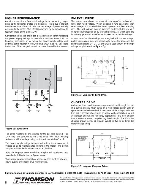
Figure 15: L/4R Drive<br />
The series resistors, R, are selected for the L/R ratio desired. For<br />
L/4R they are selected to be three times the motor winding<br />
resistance with a wattage rating = (current per winding) 2 x R.<br />
The power supply voltage is increased to four times motor rated<br />
voltage so as to maintain rated current to the motor. The power<br />
supplied will thus be four times that of a L/R drive.<br />
Note, the Unipolar motor which has a higher coil resistance, thus<br />
has a better L/R ratio than a Bipolar motor.<br />
To minimize power consumption, various devices such as a bi-level<br />
power supply or chopper drive may be used.<br />
Figure 17: Unipolar Chopper Drive.<br />
For information or to place an order in North America: 1 (203) 271-6444 Europe: (44) 1276-691622 Asia: (65) 7474-888<br />
8<br />
The specifications in this publication are believed to be accurate and reliable. However, it is the responsibility of the<br />
product user to determine the suitability of Thomson products for a specific application. While defective products will<br />
be replaced without charge if promptly returned, no liability is assumed beyond such replacement.