


You also want an ePaper? Increase the reach of your titles
YUMPU automatically turns print PDFs into web optimized ePapers that Google loves.
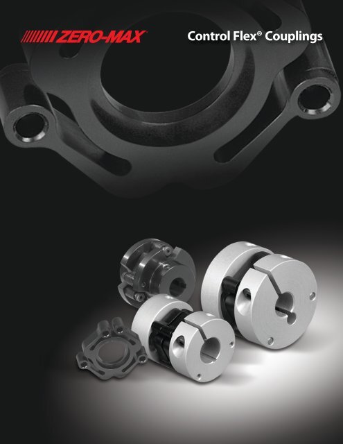
<strong>Control</strong> <strong>Flex</strong>® Couplings
CONTROL-FLEX ® COUPLINGS<br />
Ideal for encoders, <strong>Control</strong>-<strong>Flex</strong> ® Couplings are<br />
available with clamp-style zero backlash hubs or in<br />
a drop-out design for easy flexible disc changeout.<br />
The <strong>Control</strong>-<strong>Flex</strong> ® Coupling was developed to<br />
satisfy today’s higher performance requirements.<br />
To meet this goal, <strong>Zero</strong>-<strong>Max</strong> engineered<br />
a unique <strong>Control</strong>-<strong>Flex</strong> ® Disc which is based<br />
on a parallel linkage system.<br />
Because of this unique design, the reaction forces<br />
due to transmission of torque and unavoidable<br />
shaft misalignments are considerably smaller<br />
when compared with common flexible couplings.<br />
The <strong>Control</strong>-<strong>Flex</strong> ® Disc allows<br />
parallel, angular and axial shaft<br />
misalignments, and maintaining<br />
constant transmission of torque<br />
and angular velocity.<br />
Ideal for Encoder Applications!<br />
Outstanding Features and Benefits<br />
Feature .............................................. Benefit<br />
High shaft misalignment capacity ......................... Improved set up and installation time.<br />
Very low reaction loads due to misalignment ........ Improved performance and life of encoder or<br />
instrumentation device.<br />
TROL<br />
Electrically insulating flex element ........................ Added protection from stray currents.<br />
MOTION CONTROL<br />
SOLUTIONS<br />
<strong>Zero</strong> backlash .................................................... No dead band in feedback system.<br />
Low weight design ............................................. Less change to system inertia.<br />
Clamp style hubs................................................ Prevents damage to the shafting. Positive <strong>Zero</strong>-Backlash<br />
connection between the hub and shaft.<br />
485 Pantone Red<br />
®<br />
®<br />
2 www.zero-max.com Phone 800.533.1731 763.546.4300 Fax 763.546.8260
SINGLE DISC CONTROL-FLEX ® COUPLINGS<br />
Clamp-Style<br />
The construction of a <strong>Control</strong>-<strong>Flex</strong> ® Coupling consists of two hubs (to be<br />
attached to the shafts) and a center flex member. This flexible element is<br />
affixed to the hubs through pins. Clamp-style hubs provide a positive shaft<br />
connection. Special modifications are available upon request.<br />
The clamp-style <strong>Control</strong>-<strong>Flex</strong> ® Couplings are available with a single flex<br />
disc for standard torque capacity, or with two flex discs for increased<br />
torque capacity and torsional stiffness. The clamp-style hub models come<br />
standard without keyways. Keyways are available upon request.<br />
• Ideal for encoder Applications<br />
• Easy Installation<br />
• Space Saving<br />
• Electrically Insulating<br />
• Ultra low reaction loads<br />
• <strong>Zero</strong> Backlash<br />
• Maintenance Free<br />
ØD4<br />
ØD4<br />
ØD4<br />
L1<br />
L2 L1<br />
L<br />
L2<br />
L<br />
L1 L2<br />
L<br />
Single Disc<br />
BORE<br />
D2<br />
BORE<br />
D2<br />
BORE<br />
D2<br />
Single <strong>Flex</strong> Disc Clamp-Style<br />
Part No.<br />
CPL.<br />
Diam<br />
(Inch)<br />
D2<br />
Coupling<br />
Length<br />
(Inch)<br />
L<br />
Hub<br />
Length<br />
(Inch)<br />
L1<br />
Coupling Dimensions<br />
Minimum Bore <strong>Max</strong> Bore Disc<br />
Inside<br />
Diam<br />
(Inch) (mm) (Inch) (mm)<br />
(Inch)<br />
D4<br />
Disc<br />
Length<br />
(Inch)<br />
L2<br />
Net<br />
Weight<br />
(Lb)<br />
Inertia<br />
WK 2<br />
(Lb-In 2 )<br />
<strong>Max</strong>.<br />
Peak<br />
Torque<br />
(In-Lb)<br />
Performance Data<br />
<strong>Max</strong>. Torsional Stiffness<br />
Cont.<br />
Peak In Lbs. In Lbs.<br />
Torque Per Per<br />
(In-Lb) Degree Radian<br />
In Oz.<br />
Per<br />
Minute<br />
<strong>Max</strong><br />
Speed<br />
(RPM)<br />
Par<br />
(Inch)<br />
<strong>Max</strong>imum Shaft<br />
Misalignments<br />
Ang<br />
(Deg)<br />
Axial<br />
(Inch)<br />
C008P 0.748 0.62 0.219 0.125 3 0.375 10 0.28 0.19 0.020 0.0014 6 4 2.3 130 0.61 12,000 0.013 1.5 0.010<br />
MOTION CONTROL MOTION CONTROL<br />
C011P 0.984 1.00 0.374 0.125 4 0.500 12 0.41 0.25 0.057 0.0075 13 9 5.0 285 1.33 11,000 0.019 1.5 0.014<br />
SOLUTIONS<br />
SOLUTIONS<br />
C016P 1.457 1.17 0.394 0.125 4 0.750 20 0.56 0.38 0.135 0.038 45 31 16.3 930 4.35 8,000 0.028 1.5 0.021<br />
C023P 2.205 1.74 0.591 0.375 8 1.188 30 0.71 0.56 0.450 0.291 152 106 55.0 3,150 14.29 6,000 0.041 1.5 0.031<br />
C031P 2.953 2.17 0.709 0.500 12 1.500 40 1.13 0.75 1.060 1.220 361 250 75.0 4,300 20.00 5,000 0.055 1.5 0.042<br />
1) <strong>Max</strong>imum speed rating applicable at 50% or less continuous torque rating.<br />
2) As speeds approach the maximum speed rating, some applications may require dynamically balanced couplings.<br />
485 Pantone Red<br />
®<br />
www.zero-max.com Phone 800.533.1731 763.546.4300 Fax 763.546.8260<br />
®<br />
3
DOUBLE DISC CONTROL-FLEX ® COUPLINGS<br />
Clamp-Style<br />
The construction of a <strong>Control</strong>-<strong>Flex</strong> ® Coupling consists of two hubs (to be<br />
attached to the shafts) and a center flex member. This flexible element is<br />
affixed to the hubs through pins. Clamp-style hubs provide a positive shaft<br />
connection. Special modifications are available upon request.<br />
The clamp-style <strong>Control</strong>-<strong>Flex</strong> ® Couplings are available with a single flex disc<br />
for standard torque capacity, or with two flex discs for increased torque<br />
capacity and torsional stiffness. The clamp-style hub models come standard<br />
without keyways. Keyways are available upon request.<br />
• Ideal for encoder Applications<br />
• Easy Installation<br />
• Space Saving<br />
• Electrically Insulating<br />
• Ultra low reaction loads<br />
• <strong>Zero</strong> Backlash<br />
• Maintenance Free<br />
ØD4<br />
ØD4<br />
ØD4<br />
L1<br />
L2 L1<br />
L<br />
L1 L2 L2<br />
L L<br />
Double Disc<br />
BORE<br />
D2<br />
BORE<br />
D2<br />
BORE<br />
D2<br />
Double <strong>Flex</strong> Disc Clamp-Style<br />
Part No.<br />
CPL.<br />
Diam<br />
(Inch)<br />
D2<br />
Coupling<br />
Length<br />
(Inch)<br />
L<br />
Hub<br />
Length<br />
(Inch)<br />
L1<br />
Coupling Dimensions<br />
Minimum Bore <strong>Max</strong> Bore Disc<br />
Inside<br />
Diam<br />
(Inch)<br />
(Inch) (mm) (Inch) (mm) D4<br />
Disc<br />
Length<br />
(Inch)<br />
L2<br />
Net<br />
Weight<br />
(Lb)<br />
Inertia<br />
WK 2<br />
(Lb-In 2 )<br />
<strong>Max</strong>.<br />
Peak<br />
Torque<br />
(In-Lb)<br />
Performance Data<br />
<strong>Max</strong>. Torsional Stiffness<br />
Cont.<br />
Peak In Lbs. In Lbs.<br />
Torque Per Per<br />
(In-Lb) Degree Radian<br />
In Oz.<br />
Per<br />
Minute<br />
<strong>Max</strong><br />
Speed<br />
(RPM)<br />
Par<br />
(Inch)<br />
<strong>Max</strong>imum Shaft<br />
Misalignments<br />
Ang<br />
(Deg)<br />
Axial<br />
(Inch)<br />
TROL<br />
C208P 0.748 0.78 0.219 0.125 3 0.375 10 0.28 0.34 0.021 0.0014 10 7 4.6 260 1.22 10,000 0.009 1 0.007<br />
C211P MOTION 0.984 CONTROL 1.20 0.374 0.125 4 0.500 12 0.41 0.46 0.060 0.0077 24 17 9.9 570 2.63 9,000 0.012 1 0.009<br />
SOLUTIONS<br />
C216P 1.457 1.48 0.394 0.125 4 0.750 20 0.56 0.69 0.145 0.039 81 57 31.3 1,790 8.33 7,000 0.019 1 0.014<br />
C223P 2.205 2.20 0.591 0.375 8 1.188 30 0.71 1.02 0.483 0.298 274 192 110.0 6,300 29.41 5,000 0.027 1 0.020<br />
C231P 2.953 2.79 0.709 0.500 12 1.500 40 1.13 1.38 1.140 1.250 650 435 150.0 8,600 40.00 4,000 0.037 1 0.028<br />
1) <strong>Max</strong>imum speed rating applicable at 50% or less continuous torque rating.<br />
2) As speeds approach the maximum speed rating, some applications may require dynamically balanced couplings.<br />
485 Pantone Red<br />
®<br />
®<br />
4 www.zero-max.com Phone 800.533.1731 763.546.4300 Fax 763.546.8260
CONTROL-FLEX ® COUPLINGS<br />
Bolted-Style<br />
The construction of a <strong>Control</strong>-<strong>Flex</strong> ® Coupling consists of two<br />
hubs (to be attached to the shafts) and a center flex member.<br />
This flexible element is affixed to the hubs through shoulder<br />
bolts. The Bolted-Style hubs incorporate keyway and setscrew<br />
shaft attachment. <strong>Flex</strong> discs are bolted for drop-out capability.<br />
Special modifications are available upon request.<br />
• Easy Installation<br />
• Space Saving<br />
• Electrically Insulating<br />
• Large Misalignment Capacity<br />
• <strong>Zero</strong> Backlash<br />
• Maintenance Free<br />
L2<br />
L2 L1L2<br />
L1<br />
L1<br />
BORE<br />
BORE BORE<br />
ØD4<br />
ØD4 ØD4<br />
L<br />
L<br />
L<br />
ØD2<br />
ØD2 ØD2<br />
The above drawing is valid for C030P, C060P and C075P. C045P will still use the triangular style hubs.<br />
Consult factory if necessary.<br />
<strong>Control</strong>-<strong>Flex</strong> Coupling Bolted-Style<br />
Part No.<br />
CPL.<br />
Diam<br />
(Inch)<br />
D2<br />
Coupling<br />
Length<br />
(Inch)<br />
L<br />
Hub<br />
Length<br />
(Inch)<br />
L1<br />
Coupling Dimensions<br />
Minimum Bore <strong>Max</strong> Bore Disc<br />
Inside<br />
Diam<br />
(Inch)<br />
(Inch) (mm) (Inch) (mm) D4<br />
Disc<br />
Length<br />
(Inch)<br />
L2<br />
Net<br />
Weight<br />
(Lb)<br />
Performance Data<br />
MOTION CONTROL <strong>Max</strong>.<br />
SOLUTIONS<strong>Max</strong>.<br />
Cont.<br />
Inertia Peak Peak<br />
WK 2 Torque Torque<br />
(Lb-In 2 ) (In-Lb) (In-Lb)<br />
MOTION Torsional Stiffness CONTROL<br />
SOLUTIONS<br />
In Lbs. In Lbs.<br />
Per Per<br />
Degree Radian<br />
<strong>Max</strong><br />
Speed<br />
(RPM)<br />
Par<br />
(Inch)<br />
<strong>Max</strong>imum Shaft<br />
Misalignments<br />
Ang<br />
(Deg)<br />
Axial<br />
(Inch)<br />
C030P 3.00 2.750 1.00 0.375 10 1.000 25 1.125 0.750 0.78 0.345 361 250 75.0 4,300 6,300 0.055 1.5 0.042<br />
C045P 4.50 4.125 1.50 0.375 10 1.500 40 1.687 1.125 2.63 2.62 1,218 850 261.0 14,950 4,200 0.083 1.5 0.063<br />
C060P 6.00 5.500 2.00 0.625 16 2.000 55 2.250 1.500 6.24 11.03 2,887 2,000 515.0 29,500 3,100 0.111 1.5 0.083<br />
C075P 7.50 6.875 2.50 1.000 24 2.500 65 2.812 1.875 12.18 33.66 5,638 3,900 1,529.0 87,600 2,500 0.139 1.5 0.104<br />
1) <strong>Max</strong>imum speed rating applicable at 50% or less continuous torque rating.<br />
2) As speeds approach the maximum speed rating, some applications may require dynamically balanced couplings.<br />
485 Pantone Red<br />
®<br />
www.zero-max.com Phone 800.533.1731 763.546.4300 Fax 763.546.8260<br />
®<br />
5
SCHMIDT FLEXIBLE COUPLINGS<br />
B<br />
Schmidt <strong>Flex</strong>ible Couplings provide precision for slightly<br />
misaligned shafts and are designed to adapt to various<br />
drive conditions. This coupling uses precision sintered<br />
parts for the hubs which are connected to the shafts.<br />
The molded flexible center disc is preloaded on the<br />
precision shafts of the end disc which give the coupling<br />
a zero backlash condition. Different configurations of<br />
the coupling and the choice of three durometers (soft,<br />
standard, stiff) of the center disc result in the ability of<br />
this coupling to be adapted to various drive conditions.<br />
D<br />
A<br />
K<br />
F<br />
D<br />
The <strong>Flex</strong>ible Coupling may be built into a floating shaft<br />
design by including one coupling at each end of an<br />
intermediate shaft.<br />
B<br />
• Easy Installation<br />
Double Disc Spacer<br />
B<br />
Single Disc<br />
Double Disc<br />
• Electrically Insulating<br />
• <strong>Zero</strong> Backlash<br />
D A<br />
Among the many applications where the <strong>Flex</strong>ible<br />
Couplings are used include collators, printing machines,<br />
packaging machines and pumps.<br />
K<br />
F<br />
D<br />
A<br />
K<br />
F<br />
D<br />
B<br />
B<br />
B<br />
D<br />
A<br />
F<br />
D<br />
A<br />
F<br />
D<br />
A<br />
F<br />
K<br />
K<br />
K<br />
TROL<br />
D<br />
Schmidt <strong>Flex</strong>ible Couplings<br />
B<br />
Coupling Dimensions<br />
Performance Data<br />
Minimum Bore <strong>Max</strong> Bore<br />
Torsional<br />
Hub Coupling Hub<br />
A<br />
A <strong>Flex</strong>. Disc<br />
Stiffness<br />
<strong>Max</strong>imum Misalignments<br />
Diam Length Length<br />
Diam<br />
<strong>Max</strong>. (In-Lbs.<br />
Inertia Net<br />
(Inch) (Inch) (Inch)<br />
(Inch) HP/ Torque Per Par Ang Axial WK 2 Weight<br />
Part No. D B K (Inch) (mm) (Inch) (mm) F 100RPM (In-Lb) Degree) (Inch) (Deg) (Inch) (Lb-In 2 ) (Lb)<br />
A<br />
F<br />
F008A 0.750 0.812 0.281 0.250 D A 7 0.375 10 0.750 0.009 F6 4.5 0.005 1 0.008 0.004 0.06<br />
Single<br />
Disc<br />
F011A 1.125 1.375 0.500 0.250 7 0.500 12 1.250 0.025 16 14.0 0.008 1 0.011 0.04 0.25<br />
F019A 1.900 2.250 0.750 0.500 14 0.875 22 2.040 0.180 115 91.0 0.010 1 0.019 0.46 1.03<br />
K<br />
F028A 2.812 2.812 1.000 0.625 16 1.00 25 2.812 0.500 315 264.6 0.010 1 0.025 2.50 2.50<br />
K<br />
MOTION F008B CONTROL 0.750<br />
SOLUTIONS<br />
0.837 0.281 0.250 7 0.375 10 0.750 0.018 12 9.0 0.005 1 0.008 0.005 0.07<br />
F011B 1.125 1.688 0.500 0.250 7 0.500 12 1.250 0.050 32 27.0 0.008 1 0.011 0.04 0.27<br />
Double<br />
Disc<br />
B<br />
F019B 1.900 B2.875 0.750 0.500 14 0.875 22 2.040 0.360 230 214.1 0.010 1 0.019 0.55 1.12<br />
F028B 2.812 3.375 1.000 0.625 16 1.00 25 2.812 1.000 630 531.5 0.010 1 0.025 2.27 2.80<br />
D<br />
Double<br />
Disc<br />
Spacer<br />
F011C 1.125 2.125 0.500 0.250 7 0.500 12 1.250 0.025 16 7.0 0.016 2 0.020 0.05 0.34<br />
F019C 1.900 3.500 0.750 0.500 14 0.875 22 2.040 0.180 115 45.5 0.020 2 0.035 0.66 1.47<br />
A<br />
F<br />
Performance Data is based on couplings using standard durometer flex disks.<br />
Please 485 contact Pantone Red the factory for performance data and availability of couplings using non-standard durometers.<br />
®<br />
K<br />
®<br />
6 www.zero-max.com Phone 800.533.1731 763.546.4300 Fax 763.546.8260
HOW TO SELECT CONTROL-FLEX ® COUPLINGS<br />
Here’s how:<br />
The basic performance ratings listed in the table are<br />
maximum values. The graph below must be used to<br />
determine the coupling’s suitability in each application.<br />
To see if a coupling is suitable for an application,<br />
see the selection procedure on this page.<br />
When calculating torque requirements,<br />
see the service factor table provided on this page.<br />
For special designs or requirements, consult the factory.<br />
Selection Procedure:<br />
To select the proper <strong>Control</strong>-<strong>Flex</strong> ® coupling size, identify<br />
the application’s requirements for torque, misalignment,<br />
and service factor. Tentatively select a coupling based<br />
on these requirements. Find the selected coupling’s<br />
maximum rated torque and misalignment.<br />
Compute the misalignment ratio by dividing the required<br />
parallel misalignment by the maximum rated parallel<br />
misalignment. If either angular or axial misalignment are<br />
required, multiply the existing misalignment ratio by 1.2.<br />
If both angular and axial misalignment are required,<br />
multiply the misalignment ratio by 1.4.<br />
Next, compute the torque ratio. Divide the required<br />
torque including service factor by the maximum rated<br />
peak torque of the selected coupling. The actual running<br />
torque should never exceed the maximum continuous<br />
rated torque. Occasional torque spikes in the system<br />
should never exceed the maximum peak torque rating.<br />
Now that the torque and misalignment ratios are known,<br />
their effect on the coupling can be compared to the<br />
couplings operating envelope. (See Chart)<br />
If the lines representing the two performance ratios meet<br />
to the left of the shaded area, the selected coupling is<br />
appropriate for the application.<br />
If the lines meet in the shaded area, the selected<br />
coupling is not appropriate for the application, and a<br />
larger coupling size must be selected.<br />
Selection Formula:<br />
HP/100 RPM = Required HP x Service Factor x 100<br />
RPM<br />
Recommended Service Factor<br />
No Shock Load . . . . . . 1.0<br />
Light Shock Load . . . . . 1.5<br />
Medium Shock Load . . 2.0<br />
Heavy Shock Load . . . 2.5<br />
Reversing Shock Load . 3.0<br />
PERCENT MAXIMUM<br />
MISALIGNMENT RATING<br />
100<br />
80<br />
60<br />
40<br />
20<br />
0<br />
CONTROL FLEX ® COUPLING<br />
OPERATING ENVELOPE<br />
0 20 40 60 80 100<br />
MOTION CONTROL<br />
SOLUTIONS<br />
PERCENT MAXIMUM<br />
TORQUE RATING<br />
(WITH SERVICE FACTOR APPLIED)<br />
Standard Keyways - Inch Bore Hubs<br />
Standard Keyways - Metric Bore Hubs<br />
MOTION CONTROL<br />
SOLUTIONS<br />
485 Pantone Red<br />
Applications<br />
falling in the<br />
shaded area<br />
are outside<br />
the couplings<br />
capability. Select<br />
the next larger<br />
coupling and<br />
repeat selection<br />
procedure.<br />
Bore Size Keyway Bore Size Keyway<br />
Over To Over To<br />
0.437 0.562 0.125x0.062 2.250 2.750 0.625x0.312<br />
0.562 0.875 0.187x0.094 2.750 3.250 0.750x0.375<br />
0.875 1.250 0.250x0.125 3.250 3.750 0.875x0.437<br />
1.250 1.375 0.312x0.156 3.750 4.500 1.000x0.500<br />
1.375 1.750 0.375x0.187 4.500 5.500 1.250x0.625<br />
1.750 2.250 0.500x0.250 5.500 6.500 1.500x0.750<br />
Bore Size Keyway Bore Size Keyway<br />
Over To Over To<br />
10 12 4x1.8 58 65 18x4.4<br />
12 17 5x2.3 65 75 20x4.9<br />
17 22 6x2.8 75 85 22x5.4<br />
22 30 8x3.3 85 95 25x5.4<br />
30 38 10x3.3 95 110 28x6.4<br />
38 44 12x3.3 110 130 32x7.4<br />
44 50 14x3.8 130 150 36x8.4<br />
50 58 16x4.3 150 170 40x9.4<br />
Note: Inch bore hubs will be supplied with inch size setscrews.<br />
Metric bore hubs will be supplied with metric size setscrews.<br />
Standard keyways are for square keys. Keyways for rectangular<br />
keys are available - consult factory.<br />
<strong>Zero</strong>-<strong>Max</strong> Configurable 3D CAD Downloads<br />
New <strong>Zero</strong>-<strong>Max</strong> Configurable<br />
3D CAD Downloads.<br />
www.zero-max.com<br />
®<br />
www.zero-max.com Phone 800.533.1731 763.546.4300 Fax 763.546.8260<br />
®<br />
7
ServoClass ® Couplings<br />
Designed for demanding<br />
servomotor applications. <strong>Zero</strong><br />
backlash, high torsional stiffness<br />
coupling. Features flexible metal<br />
discs and keyless clamp-type<br />
mounting hubs. Couplings are<br />
RoHS compliant.<br />
ETP ® Shaft Locking Connections<br />
Designed for quick, easy and<br />
accurate assembly of mounted<br />
shaft components. Both inch and<br />
metric bore connections are<br />
available from stock.<br />
CD ® Couplings<br />
These high performance couplings<br />
out last bellows and steel disc<br />
design couplings. The unique design<br />
of the composite disc enables<br />
the CD Couplings ® to withstand<br />
punishing applications and deliver<br />
high precision performance.<br />
Roh’lix ® Linear Actuators<br />
Roh’Lix ® Linear Actuators convert<br />
rotary motion into precise linear<br />
motion. Available in five models.<br />
Roh’Lix ® actuators have thrust ratings<br />
from 5 to 200 lbs. All models<br />
feature built in overload protection.<br />
Schmidt ® Offset Couplings<br />
Schmidt ® Offset Couplings are<br />
designed to handle high amounts<br />
of parallel offset up to 17.00".<br />
Standard models with torque<br />
capacities up to 459,000 in-lbs.<br />
Adjustable Speed Drives<br />
Easy to install and maintenance free.<br />
<strong>Zero</strong>-<strong>Max</strong> Drives offer infinitely<br />
variable speeds from 0 rpm to 1/4<br />
of input rpm. 5 models with torque<br />
ranges from 12 in-lbs to 200 in-lbs.<br />
Overload Safety Couplings<br />
Torq-Tender ® Couplings provide<br />
reliable overload protection in any<br />
mechanical power transmission<br />
system. Torque ranges from 2 to<br />
3000 in-lbs.<br />
Crown ® Gear Drives<br />
Crown ® Gear Drives are available with<br />
1:1 and 2:1 ratios. High quality AGMA<br />
class 10 spiral bevel gears. Stainless<br />
steel shafts and aluminum housings are<br />
standard on all Crown ® Gear Drives.<br />
<strong>Control</strong>-<strong>Flex</strong> ® Couplings<br />
<strong>Control</strong>-<strong>Flex</strong> ® Couplings are zero<br />
backlash couplings designed for<br />
encoder and instrumentation<br />
type applications.<br />
OHLA ® Overhung Load Adapters<br />
OHLA ® Overhung Load Adapters are<br />
designed to eliminate radial and axial<br />
loads from a hydraulic pump or motor.<br />
11 models available for mounts from<br />
SAE A to SAE F.<br />
Warranty. <strong>Zero</strong>-<strong>Max</strong>, Inc. the manufacturer, warrants that for a period of 12 months from date of shipment it will repair, or at its option, replace any new apparatus which proves defective in material or workmanship, or<br />
which does not conform to applicable drawings and specifications approved by the manufacturer. All repairs and replacements shall be F.O.B. factory. All claims must be made in writing to the manufacturer. • In no event<br />
and under no circumstances shall manufacturer be liable for (a) damages in shipment; (b) failures or damages due to misuse, abuse, improper installation or abnormal conditions of temperature, dirt, water or corrosives; (c)<br />
failures due to operation, intentional or otherwise, above rated capacities, and (d) non-authorized expenses for removal, inspection, transportation, repair or rework. Nor shall manufacturer ever be liable for consequential<br />
and incidental damages, or in any amount greater than the purchase price of the apparatus. • <strong>Zero</strong> <strong>Max</strong>, Inc. reserves the right to discontinue models or to change specifications at any time without notice. No discontinuance<br />
or change shall create any liability on the part of <strong>Zero</strong>-<strong>Max</strong>, Inc. in respect to its products in the hands of customers or products on order not incorporating such changes even though delivered after any such change. • This<br />
warranty is in LIEU OF ALL OTHER WARRANTIES, EXPRESS OR IMPLIED, INCLUDING (BUT NOT LIMITED TO) ANY IMPLIED WARRANTIES OF MERCHANTABILITY OR FITNESS FOR A PARTICULAR PURPOSE. THE TERMS OF THIS<br />
WARRANTY CONSTITUTE ALL BUYER’S OR USER’S SOLE AND EXCLUSIVE REMEDY, AND ARE IN LIEU OF ANY RIGHT TO RECOVER FOR NEGLIGENCE, BREACH OF WARRANTY, STRICT TORT LIABILITY OR UPON ANY OTHER THEORY.<br />
Any legal proceedings arising out of the sale or use of this apparatus must be commenced within 18 months of the date of purchase. • CAUTION: Rotating equipment must be guarded. Also refer to OSHA specifications and<br />
recommendations. • <strong>Zero</strong>-<strong>Max</strong>® , CD ® , ETP ® , ServoClass ® , Torq-Tender ® , <strong>Control</strong>-<strong>Flex</strong> ® , Posi-Lok ® , Roh’Lix ® , Crown ® , Schmidt ® and OHLA ® are registered trademarks of <strong>Zero</strong>-<strong>Max</strong>, Inc. In U.S.A.<br />
©<strong>Zero</strong>-<strong>Max</strong> 2017 Printed in U.S.A.<br />
13200 Sixth Avenue North, Plymouth, Minnesota 55441-5509<br />
Phone 800.533.1731 763.546.4300 FAX 763.546.8260<br />
zero-max.com


