

Reactionless Propulsion and Active Force - Practical Guide to Free ...
Reactionless Propulsion and Active Force - Practical Guide to Free ...
Reactionless Propulsion and Active Force - Practical Guide to Free ...

Create successful ePaper yourself
Turn your PDF publications into a flip-book with our unique Google optimized e-Paper software.
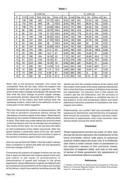
This fact dis<strong>to</strong>rted the pattern of measurements, <strong>and</strong><br />
we had <strong>to</strong> introduce correction fac<strong>to</strong>rs during the<br />
calculation of rotation speed of the rollers. These fac<strong>to</strong>rs<br />
depend on the number of fallen down or adhered rollers<br />
in pairs. This table was made taking in<strong>to</strong> account these<br />
correction fac<strong>to</strong>rs <strong>and</strong> it is an average one according <strong>to</strong><br />
the results of five tests. As we can see from the table,<br />
no self-acceleration of the rollers was found. After the<br />
speed reaches a particular value of 8,5 rps, the speed<br />
of the rollers stabilizes <strong>and</strong> does not increase in spite of<br />
the growth of rotation speed of the ro<strong>to</strong>r magnet.<br />
Also we can see from the Table 1 that the rollers always<br />
have a tendency <strong>to</strong> retard <strong>and</strong> after the full separation<br />
with the voltage of 20-23 V.<br />
Concerning the polarity of magnet location we can say<br />
that it does not influence the rotation speed of the ro<strong>to</strong>r<br />
<strong>and</strong> rollers in the limits of miscalculation in<br />
determination of speed <strong>and</strong> voltage in the given<br />
experiment. Some differences in speed are defined only<br />
by mechanical characteristics of the rollers <strong>and</strong> surface<br />
of the fixture, which was used for revolving around. We<br />
Page 244<br />
Table 1<br />
N- pole up S - pole up<br />
# U (V) I mA freg. rot rps freg. rol rps I mA freg. rot. rps freg. rol. rps<br />
1 120 196 943 37.72 102.5 8.54 199 941 37.64 102 8.50<br />
2 110 181 900 36 102.5 8.54 183 901 36.04 102 8.50<br />
3 100 170 857 34.28 102.5 8.54 172 858 34.32 102 8.50<br />
4 90 160 818 32.72 102.5 8.54 162 818 32.72 102 8.50<br />
5 80 157 778 31.12 102.5 8.54 155 778 31.12 102 8.50<br />
6 70 149 738 29.52 102.5 8.54 150 738 29.52 102 8.50<br />
7 60 147 694 27.76 102.5 8.54 146 694 27.76 102 8.50<br />
8 50 148 650 26 102.5 8.54 148 650 26 102 8.50<br />
9 40 154 599 23.96 102.5 8.54 154 599 23.96 102 8.50<br />
10 30 170 530 21.2 101 8.42 169 533 21.32 100.5 8.38<br />
11 25 183 480 19.2 97 8.08 180 484 19.36 97 8.08<br />
12 23 199 454 18.16 93 7.75 193 457 18.28 93.5 7.79<br />
13 21 210 418 16.72 81 6.75 218 426 17.04 79.5 6.63<br />
14 19 219 394 15.76 79 6.58 234 381 15.24 77 6.42<br />
15 17 239 351 14.04 72.5 6.04 255 339 13.56 68.5 5.71<br />
16 15 265 295 11.8 70.5 5.88 280 266 10.64 67 5.58<br />
17 13 290 212 4.48 67 5.58 300 200 8 65 5.42<br />
18 12 330 56 2.24 61.5 5.13 300 153 6.12 48 4.00<br />
Here, like in the previous example, two cases are<br />
considered. They are the case, when the magnet was<br />
installed its north pole up <strong>and</strong> an opposite case. The<br />
poles of the rollers change accordingly. We should note<br />
that with the slow change of power supply voltage,<br />
we practically always observed the instability of the<br />
trajec<strong>to</strong>ries of the rollers <strong>and</strong> their tailing from the<br />
operating surface, which led <strong>to</strong> the adhesion of one or<br />
some pairs of the rollers <strong>to</strong>gether.<br />
should say that the outside surfaces of the rollers <strong>and</strong><br />
the surface were made of the same material (aluminum)<br />
that’s why they have a tendency of attrition even during<br />
one experiment. (10 minutes). Due <strong>to</strong> this reason we<br />
couldn’t get the full reiteration, but the accuracy of<br />
measurements was sufficient <strong>to</strong> establish the fact of<br />
full absence of the self-acceleration effects <strong>and</strong> some<br />
differences between polarities of installation the ro<strong>to</strong>r<br />
magnet <strong>and</strong> rollers.<br />
Unfortunately, we couldn’t find any anomalies in the<br />
temperature distribution <strong>and</strong> distribution of magnetic<br />
field around the converter. “Magnetic <strong>and</strong> heat walls”<br />
discovered in experiments with a big converter were<br />
almost absent around the small device.<br />
Conclusion<br />
These experiments proved the point of view that<br />
during the device operation the nonlinearity of the<br />
wave processes, which take place in quantum<br />
medium (ether) plays the main role. It is evidently,<br />
that there is some critical value of parameters in<br />
the magnetic system of the converter (mass,<br />
induction of magnetic field), <strong>and</strong> only in the case<br />
of excess of these parameters the appearance of<br />
above-mentioned effects is possible.<br />
References<br />
1. V.Roshin, S.M.Godin An Experimental Investigation of Physical<br />
Effects In a Dynamic Magnetic System, New Energy Technologies.<br />
Issue #1, July-August 2001, pp.3-5.


