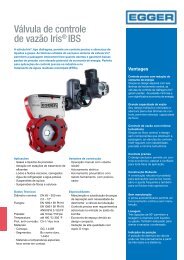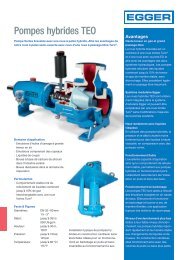
Iris® Process Control Valve - Energy-saving regulation of activated air
Creation & delivery of dissolved oxygen used in the activated sludge process consumes nearly 60% of the energy in the wastewater treatment plant. Finally, Biological processes can be optimized, Blower discharge pressures reduced, DO set-points lowered, and energy saved as a result of the Iris valve’s superior «linear» flow characteristics providing stable, accurate, repeatable, and reliable air flow regulation. Over the past 40 years, the Egger Iris® flow control valve has been successfully used in hundreds of wastewater treatment plants as the best solution for precise air flow regulation to the aeration tanks.
Creation & delivery of dissolved oxygen used in the activated sludge process consumes nearly 60% of the energy in the wastewater treatment plant. Finally, Biological processes can be optimized, Blower discharge pressures reduced, DO set-points lowered, and energy saved as a result of the Iris valve’s superior «linear» flow characteristics providing stable, accurate, repeatable, and reliable air flow regulation.
Over the past 40 years, the Egger Iris®
flow control valve has been successfully
used in hundreds of wastewater
treatment plants as the best solution
for precise air flow regulation to the
aeration tanks.

You also want an ePaper? Increase the reach of your titles
YUMPU automatically turns print PDFs into web optimized ePapers that Google loves.
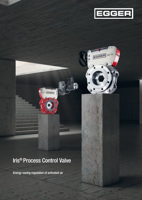
Iris ® <strong>Process</strong> <strong>Control</strong> <strong>Valve</strong><br />
<strong>Energy</strong>-<strong>saving</strong> <strong>regulation</strong> <strong>of</strong> <strong>activated</strong> <strong>air</strong>
Improved process control with a potential<br />
20 % blower energy reduction<br />
Creation and delivery <strong>of</strong> dissolved oxygen used in the <strong>activated</strong> sludge process consumes up to 60% <strong>of</strong> the energy<br />
in the wastewater treatment plant. Finally, Biological processes can be optimized, Blower discharge pressures<br />
reduced, DO set-points lowered, and energy saved as a result <strong>of</strong> the <strong>Iris®</strong> valve’s superior «linear» flow characteristics<br />
providing stable, accurate, repeatable, reliable <strong>air</strong> flow <strong>regulation</strong>, and process control.<br />
Over the past 40 years, the Egger <strong>Iris®</strong><br />
flow control valve has been successfully<br />
used in hundreds <strong>of</strong> wastewater<br />
treatment plants as the best solution<br />
for precise <strong>air</strong> flow <strong>regulation</strong> to the<br />
aeration tanks.<br />
Engineered for your plant – <strong>Iris®</strong><br />
valve sizing and selection process<br />
Plant operating parameters including<br />
system pressure (static & dynamic),<br />
blower discharge pressure, discharge<br />
<strong>air</strong> temperatures, and allowable pressure<br />
drop across the valve enables<br />
engineers at Egger to properly size<br />
and select the appropriate flow control<br />
valve for your system.<br />
SCADA Systems, PID loops, and<br />
Algorithms<br />
Constant pressure control: system<br />
pressures are kept constant to control<br />
flows.<br />
Most Open <strong>Valve</strong>: uses the <strong>Iris®</strong> valve’s<br />
characteristic curve with constant<br />
pressure control, blower speed, valve<br />
position at full or partial flows, and flow<br />
rate in each dropleg. This requires a<br />
large control range.<br />
<strong>Valve</strong> characteristic curve AKL<br />
The valve characteristic curve is required<br />
to dimension a valve in accordance<br />
with DIN EN 60534 (ANSI /<br />
ISA-75.01.01). The dependence <strong>of</strong> the<br />
flow coefficient on the stroke is known<br />
as the valve characteristic curve.<br />
The flow coefficient or C V<br />
(K V<br />
in<br />
metric system) describes its throughput<br />
capacity. This is determined on a<br />
test rig at constant differential pressure<br />
(1 psig) and at different valve<br />
settings.<br />
Delivery pressure characteristic curve<br />
Constant pressure control<br />
Most Open <strong>Valve</strong> (MOV)<br />
p valve<br />
Pressure p<br />
p dynamic<br />
Dynamic pressure losses<br />
Static pressure losses<br />
p static<br />
Blower pressure<br />
Q min<br />
Q norm<br />
Q max<br />
Flow Q
Dimensioning <strong>of</strong> an <strong>Iris®</strong> diaphragm control valve according to DIN EN 60534<br />
High quality <strong>regulation</strong> range<br />
Flow Q [Nm 3 / h or SCFM]<br />
BKL<br />
AKL<br />
Gain <strong>of</strong> the BKL<br />
Stroke <strong>Valve</strong> [%]<br />
Calculation <strong>of</strong> the throughput for gases with temperature correction<br />
Metric (K,)<br />
US Units (C v<br />
)<br />
∆p · p<br />
Q N<br />
= 514 · K V<br />
·<br />
2<br />
q<br />
ρ N · T N<br />
= 1.360 · Y · C V<br />
·<br />
1<br />
Q N<br />
Volume throughput <strong>of</strong> gases in a normal state (0°C, 1013 mbar) Nm 3 / h<br />
ρ N<br />
Density <strong>of</strong> gases in a normal state kg / Nm 3<br />
Δp Pressure differential bar<br />
p 2<br />
Absolute pressure downstream <strong>of</strong> the valve bar abs<br />
T 1<br />
Absolute temperature upstream <strong>of</strong> the valve ° K<br />
q N<br />
Volumetric flow rate (20°C, 14.69 Pisa) scfh<br />
G g<br />
Gas specific gravity 1 for <strong>air</strong>, dimensionless<br />
Δp Differential pressure psi<br />
p 1<br />
Upstream absolute static pressure psia<br />
T 1<br />
Upstream absolute temperature ° R<br />
Relationship between C v<br />
and Kv: K v<br />
= 0.865 · C v<br />
or C v<br />
= K v<br />
/0.865<br />
∆p · p 1<br />
T 1 · Gg<br />
Y Expansion factor dimensionless<br />
Operating characteristic BKL<br />
However, the valve characteristic only<br />
applies at constant differential pressure.<br />
Depending on the control valve<br />
settings, widely varying pressure<br />
losses occur under real operating<br />
conditions. This variable differential<br />
pressure at the control valve and the<br />
dynamic pressure losses in the system<br />
produce a distortion <strong>of</strong> the characteristic<br />
curve (see diagram). The operating<br />
characteristic represents the real<br />
relationship between the stroke and<br />
the throughput <strong>of</strong> a control valve. It is<br />
calculated from the valve characte ristic<br />
curve (C V<br />
coefficient curve) and the<br />
aforementioned operating data.<br />
Gain V PV<br />
Generally, a linear operating characteristic<br />
is aimed for. However, under<br />
real-life conditions the operating data<br />
fluctuates significantly, which results in<br />
different operating characteristics. A<br />
certain range <strong>of</strong> high control quality is<br />
defined in measurement and control<br />
technology. This «stable» range is<br />
between 0.5 and 2.0 in case <strong>of</strong> an<br />
increase in the operating characteristic<br />
(or also an increase in V PV<br />
). The basic<br />
requirement for uninterrupted, wide<br />
and stable control is an equal percentage<br />
linear characteristic curve.<br />
The precise, linear, repeatable, and<br />
stable properties <strong>of</strong> the <strong>Iris®</strong> flow<br />
control valve allow for cost-effective<br />
PID control loops to be easily set-up.<br />
The ideal valve for ammonia based<br />
aeration control (ABAC).
Thanks to systematic further development,<br />
with the third generation<br />
Egger is introducing a modern and<br />
compact version <strong>of</strong> the tried-andtested<br />
Egger <strong>Iris®</strong> valve.<br />
Maintenance free<br />
A re-designed spindle nut assembly<br />
is manufactured using a selflubricating<br />
thermoplastic material<br />
which permits maintenance free<br />
operation. No longer is regular<br />
lubrication <strong>of</strong> the threaded spindles<br />
required.<br />
Compact<br />
The <strong>Iris®</strong> flow control valve’s<br />
compact in design <strong>of</strong>fers proven<br />
accurate, stable, and repeatable<br />
flow control in a compact, space<strong>saving</strong><br />
installation.<br />
Circular opening and closing<br />
The six segments <strong>of</strong> the <strong>Iris®</strong> flow<br />
control valve are arranged to form<br />
a circular opening similar to a camera<br />
aperture. The segments can<br />
be infinitely adjusted.<br />
Free flow cross-section<br />
At 100 % open, the segments are<br />
completely out <strong>of</strong> the flow stream to<br />
ensure there are no constrictions in<br />
the cross-section which results in<br />
high C V<br />
values.<br />
Central closing flow axis<br />
Our unique centrally closing flow<br />
axis and rounded edges result in a<br />
near perfect laminar flow pr<strong>of</strong>ile<br />
helping to reduce noise emissions<br />
and improve inlet flow paths for<br />
accurate flow measurements.<br />
Egger <strong>of</strong>fers a measurement and<br />
control system with integrated<br />
mass flow meter as well as hydraulically<br />
optimised reduction parts.<br />
Ideal control characteristic<br />
shape in accordance with<br />
DIN EN 60534 (ANSI / ISA-<br />
75.01.01)<br />
The <strong>Iris®</strong> valve’s K V<br />
(C V<br />
) value is<br />
certified in accordance with<br />
DIN EN 60534 by independent<br />
labora tories in Europe & North<br />
America. <strong>Iris®</strong> has the ideal characteristic<br />
curve required to for<br />
stable, linear, accurate and repeatable<br />
control.<br />
Robustness and long service life<br />
<strong>Iris®</strong> valves are proven tough and<br />
extremely reliable for control systems<br />
with high switching frequencies.<br />
Headquarters<br />
Emile Egger & Cie SA<br />
Route de Neuchâtel 36<br />
2088 Cressier NE (Switzerland)<br />
Phone +41 (0)32 758 71 11<br />
info@eggerpumps.com<br />
1301.en - 11.2023<br />
Subisidiary <strong>of</strong>fices and national<br />
agency <strong>of</strong>fices<br />
Austria<br />
Belgium<br />
China<br />
France<br />
Germany<br />
Great Britain<br />
India<br />
Italy<br />
Spain<br />
USA<br />
www.eggerpumps.com<br />
For more information, please visit<br />
our website at<br />
www.eggerpumps.com