IBC SOLAR QUALITY: MODULE TEST PROCEDURE
IBC SOLAR Module Testing Methods Brochure
IBC SOLAR Module Testing Methods Brochure

You also want an ePaper? Increase the reach of your titles
YUMPU automatically turns print PDFs into web optimized ePapers that Google loves.
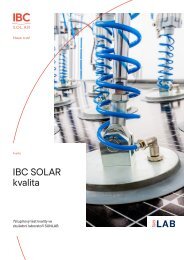
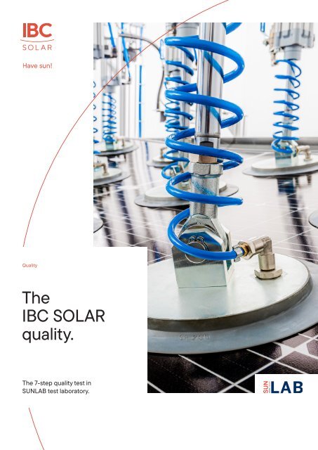
Quality<br />
The<br />
<strong>IBC</strong> <strong>SOLAR</strong><br />
quality.<br />
The 7-step quality test in<br />
SUNLAB test laboratory.
Qualified testing<br />
of solar modules.<br />
Photovoltaic modules and components are exposed to a<br />
wide range of impacts, whether weather, manufacturing<br />
or wear and tear.<br />
In the SUNLAB test laboratory over an area of around<br />
250 sq. m, PV specialists implement seven different test<br />
procedures to determine whether the products deliver<br />
what they promise. In this way, our customers benefit<br />
from maximum security in terms of warranty, guarantee<br />
and recourse.<br />
Our quality promise<br />
at a glance:<br />
• All components come from reputable and<br />
certified manufacturers<br />
• Unique quality assurance measures prevalent<br />
throughout the industry<br />
• Comprehensive incoming goods inspections,<br />
based on DIN ISO 2859-1<br />
2 3
The measure<br />
of all things.<br />
South Pole<br />
and Sahara.<br />
Determining the highest performance<br />
DIN EN IEC 61215-2:2022-02 | MQT02<br />
Temperature cycling test<br />
DIN EN IEC 61215-2:2022-02 | MQT11<br />
Purpose Determining the highest output of the PV modules before and after environmental impact<br />
tests. The defined value is used as the starting point for the incoming goods inspection and<br />
processing complaints.<br />
Test device BBA sunlight simulator according to the IEC 60904-9 standard<br />
B B A<br />
Irradiance<br />
Homogeneity<br />
Spectrum<br />
Process • Comparison object is a PV reference module according to IEC 60904-2 that is stored<br />
in a darkroom with UV-reduced light and at a constant temperature of +25°C (±2), therefore<br />
its photovoltaic parameters are stable<br />
• The PV reference module and the test module are mounted in a recording device that<br />
is vertical to the radiation direction<br />
• The voltage curve is measured according to IEC 60904-1<br />
Standard • Radiation strength: 1,000 W/m²<br />
Test parameter • Test temperature: +25°C (±5)<br />
• Measurement period: 10 ms<br />
• Test period: 2 minutes<br />
• Possibility of low-light measurement from 100 W/m² to 1,000 W/m² in increments of 100<br />
Purpose<br />
Test device<br />
Determining the suitability of PV modules. Thermal mismatches or material fatigue, for<br />
example, can be prevented in advance as a result of simulated temperature fluctuations.<br />
Climate chamber with:<br />
• Automatic temperature control and air circulation<br />
• Function for preventing condensation on the PV module<br />
• Integrated module fastening rails for improved air circulation<br />
• Temperature gauge<br />
• Continuous electricity supply<br />
Process • Attachment and inclusion of PV modules at room temperature<br />
• Temperature influence of -40°C to +80°C with power supply to the PV modules<br />
• Total cycle duration: 6 hours<br />
• Number of cycles: 200<br />
• At least 1 hour recovery time at room temperature<br />
Tests before • Visual inspection (DIN EN 61215/10.1)<br />
and after the • Measurement to determine the maximum output with electroluminescence imaging<br />
inspection (DIN EN 61215/10.2)<br />
• Testing the insulation resistance subject to water submergence (DIN EN 61215/10.15)<br />
+85<br />
+80<br />
At least<br />
10 minutes<br />
at +85°C<br />
Applied current<br />
Modul temperatur (°C)<br />
+25<br />
Max. temperature fluctuation<br />
per hour ≤ 100°C<br />
Repetition up to defined<br />
number of cycles<br />
-40<br />
At least<br />
10 minutes<br />
at -40°C<br />
Longest cycle time<br />
1 2 3 4 5 6 7 8 Time (h)<br />
4 5
For bending<br />
and breaking.<br />
Perfect climate<br />
for hard facts.<br />
Static mechanical load testing<br />
DIN EN IEC 61215-2:2022-02 | MQT16<br />
Heat test with humidity<br />
DIN EN IEC 61215-2:2022-02 | MQT13<br />
Purpose Determining the suitability of the PV module to withstand a static minimum load.<br />
Test device Loading table<br />
• Test rig with a frame made from extruded aluminium profiles for absorbing the<br />
mechanical test loads<br />
• 15 pneumatically-controlled test cylinders<br />
• Vacuum cups at the ends of the cylinders enable pressure and suction loads<br />
• Force measurement frame with 4 force sensors to calculate the force exerted on the<br />
module/the holder<br />
• Control software to calculate the total force based on signals from the 4 force sensors<br />
Process • Assembling the PV module with the holder stipulated by the manufacturer. If there are<br />
numerous attachment variants, all of these variants will be tested<br />
• The design load stipulated by the manufacturer will be applied<br />
- Positive design load → Download pressure<br />
- Negative design load → Upward tension<br />
• The same procedure is also applied to the reverse side<br />
Standard • Minimum test force: 2,400 Pa (≙244.73 kg/m²)<br />
Test parameter • Test temperature: +25°C (±5)<br />
• Load duration: 1 hour<br />
• Repetition: 3 cycles<br />
• Load evenness: ±5%<br />
Tests before • Visual inspection (DIN EN IEC 61215/10.1)<br />
and after the • Measurement to determine the maximum output with electroluminescence imaging<br />
inspection (DIN EN IEC 61215/10.2)<br />
• Testing the insulation resistance subject to water submergence (DIN EN IEC 61215/10.15)<br />
Purpose<br />
Test device<br />
Determining the suitability of PV modules to withstand the long-term penetration of<br />
moisture.<br />
Climate chamber with:<br />
• Automatic temperature control and air circulation<br />
• Function for preventing condensation on the PV module<br />
• Integrated module fastening rails for improved air circulation<br />
• Temperature gauge<br />
Process • Attachment and inclusion of PV modules at room temperature<br />
• Conducting the test according to IEC 60068-2-78 at +85°C and a relative humidity<br />
of 85%<br />
• Total cycle duration: 1,000 hours<br />
• At least 2 to 4 hours recovery time at room temperature and a relative humidity<br />
below 75%<br />
Tests before • Visual inspection (DIN EN 61215/10.1)<br />
and after the • Measurement to determine the maximum output with electroluminescence<br />
inspection imaging (DIN EN 61215/10.2)<br />
• Testing the insulation resistance subject to water submergence (DIN EN 61215/10.15)<br />
Module temperature (°C)<br />
Relative humidity<br />
+85<br />
85%<br />
+25<br />
0<br />
500<br />
1,000 Time (h)<br />
6 7
In light of<br />
the truth.<br />
Still<br />
watertight?<br />
Electroluminescence measuring for PV modules<br />
IEC 82/1062/CD:2016<br />
Measuring the insulation resistance<br />
under wet conditions<br />
DIN EN IEC 61215-2:2022-02 | MQT15<br />
Explanation When applying an electrical voltage to the PV module, light will be emitted by the materials<br />
(EL for short) that is captured by an electroluminescent camera.<br />
Purpose Electroluminescence images of PV modules reliably indicate possible material defects,<br />
such as hair-line cracks.<br />
Test device • Camera: Great Eyes GE 2048 2048 FI model<br />
• CCD sensor specification: 2048 x 2048 pixel format<br />
• Camera specifications: Hermetically sealed vacuum head<br />
• Software: Integrated and can be controlled with a PC<br />
Freely-selectable current and voltage values<br />
Process • The PV module is brought into a darkroom to ensure high-quality images<br />
• The image angle to the surface must be observed<br />
• The connecting cables (+) (-) are connected correctly to the test object<br />
• A foreign light source must not be used<br />
• The electrical DC power supply is fed in with a voltage that Isc must reach. In order to<br />
ensure identical image quality, the DC power supply that is applied is not changed for<br />
the same module types<br />
• Test temperature: +20°C to +25°C<br />
• A temperature fluctuation of 1°C must not be exceeded during the measurement<br />
Purpose Evaluating the insulation of the PV module when exposed to moisture. Rain, dew or melted<br />
snow must not enter active parts of the PV module in order to prevent corrosion, earth<br />
faults and safety hazards.<br />
Test device Water tank for PV modules with:<br />
• A DC voltage source that can generate a 1,500 V system voltage and is equipped with a<br />
current limiter<br />
• Measuring device to determine the insulation resistance<br />
Process • Prepare water so that the temperature is at +25°C (±2)<br />
• Insert the PV module into the water basin until it is covered<br />
• Do not immerse the junction boxes too. They will be covered with water<br />
• The short-circuited output terminals of the PV module will be connected to the positive<br />
terminal of the test device<br />
• The water must be connected to the negative terminal of the test device with a suitable<br />
metallic conductor<br />
• Test period: 3,5 minutes<br />
• If modules have an area of greater than 0.1 m², the measured insulation resistance<br />
multiplied by the module area must not be less than 40 MΩ x m²<br />
Example Measured insulation resistance for module area exceeding 0.1 m²<br />
<strong>IBC</strong> <strong>SOLAR</strong> standard size = 1.722 mm x 1.134 mm = 1,92 m²<br />
40 MΩ x 1,92 m² = 78,08 MΩ<br />
Short-circuited terminals<br />
Positive terminal of the test device<br />
Test device with measuring<br />
device to determine<br />
insulation resistance<br />
+ –<br />
Junction box<br />
PV module<br />
Metallic conductor<br />
negative terminal<br />
Electroluminescence image of an intact PV module<br />
Electroluminescence image of a faulty PV module<br />
Water tank with water<br />
8 9
Just don´t<br />
let up!<br />
Repeatedly tested<br />
Detection of voltage-induced degradation<br />
DIN IEC/TS 62804-1:2017-05<br />
longer lasting.<br />
Purpose System load of PV modules in an environment with humid heat. Qualification requirement<br />
of PV modules for the charge produced by the system voltage during operations. Early<br />
detection of degradation to prevent output losses and losses of earnings at an early stage.<br />
Test device Climate chamber<br />
Process • Using a high DC voltage source with current limiter<br />
• Attaching and introducing the PV modules into the climate chambers with<br />
temperature and moisture control<br />
Quality is our top priority – both for our own brand and for<br />
external brands in our portfolio.<br />
That’s why you receive photovoltaic components developed<br />
in-house under the <strong>IBC</strong> <strong>SOLAR</strong> brand, into which we have<br />
poured years of experience and expertise. In addition to the<br />
quality tests in the SUNLAB, <strong>IBC</strong> <strong>SOLAR</strong> modules undergo<br />
long-term tests under real environmental conditions on a<br />
3,000 square metre test facility.<br />
Standard • Air temperature: +60°C (±2)<br />
Test parameter <strong>IBC</strong> <strong>SOLAR</strong> conducts tests in a stringent process at +85°C (±2)<br />
• Relative humidity: 85% (±5)<br />
• Test period: 96 hours<br />
• Voltage: 1,000V – 1,500V<br />
Tests before • Determining the maximum output according to DIN EN 612162:2017-08 (MQT02)<br />
and after the • Electroluminescence test according to IEC 82/1062/CD:2016<br />
inspection<br />
We source third-party products from reputable manufacturers.<br />
We subject the products to extensive incoming goods<br />
inspections and also test them at our own test facility.<br />
This is how we guarantee that our systems always meet the<br />
highest standards. They are certified according to current<br />
standards and evaluated by globally recognised independent<br />
institutes (TÜV, VDE and Fraunhofer ISE).<br />
We are convinced by the quality of our products. That’s<br />
why we give exceptionally long product guarantees.<br />
10<br />
11
<strong>IBC</strong> <strong>SOLAR</strong> AG<br />
Am Hochgericht 10<br />
96231 Bad Staffelstein<br />
Germany<br />
+49 9573 9224-0<br />
info@ibc-solar.com<br />
www.ibc-solar.com<br />
Article number: 9001400100 • As of: 11/2022