
You also want an ePaper? Increase the reach of your titles
YUMPU automatically turns print PDFs into web optimized ePapers that Google loves.
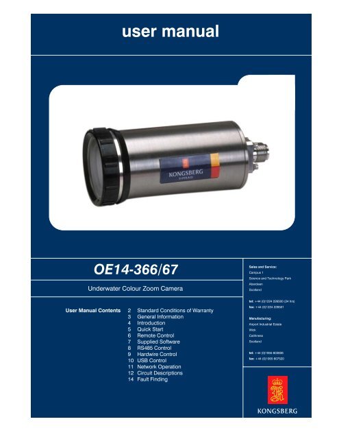
user manual<br />
OE14-366/67<br />
Underwater Colour <strong>Zoom</strong> Camera<br />
User Manual Contents<br />
2 Standard Conditions of Warranty<br />
3 General Information<br />
4 Introduction<br />
5 Quick Start<br />
6 Remote Control<br />
7 Supplied Software<br />
8 RS485 Control<br />
9 Hardwire Control<br />
10 USB Control<br />
11 Network Operation<br />
12 Circuit Descriptions<br />
14 Fault Finding<br />
OE14-366/67<br />
Sales and Service:<br />
Campus 1<br />
Science and Technology Park<br />
Aberdeen<br />
Scotland<br />
tel: +44 (0)1224 226500 (24 hrs)<br />
fax: +44 (0)1224 226501<br />
Manufacturing:<br />
Airport Industrial Estate<br />
Wick<br />
Caithness<br />
Scotland<br />
tel: +44 (0)1955 603606<br />
fax: +44 (0)1955 607520
User<br />
Manual<br />
JBA Explorer.lnk<br />
OE14-366/67<br />
Underwater Colour <strong>Zoom</strong> Camera<br />
Kongsberg Maritime Ltd<br />
User Manual: OE14-366 Colour <strong>Zoom</strong> Camera - 5023 - 2<br />
Sales and Service: Campus 1, Science and Technology Park, Aberdeen, Scotland<br />
tel: +44 (0)1224 226500 (24 hrs) fax: +44 (0)1224 226501<br />
colour<br />
STANDARD CONDITIONS OF WARRANTY and GENERAL INFORMATION<br />
(The Conditions and Information form part of the Company’s conditions of trading)<br />
STANDARD CONDITIONS OF WARRANTY<br />
Instruments sold by Kongsberg Maritime Limited (hereinafter called the ‘Company’) are warranted only as<br />
stated below:<br />
Subject to the exceptions and upon the conditions specified below, the Company agrees to correct, either by<br />
repair of at its election, by replacement, any defect of material or workmanship which develops within one<br />
year after delivery of the instrument to the original purchaser by the Company or by an authorised<br />
representative, provided that investigation and factory inspection by the Company discloses that such defect<br />
developed under normal and proper use.<br />
The exceptions and conditions mentioned above are the following:<br />
a. If any component or accessory manufactured by the Company such as glassware, optical components,<br />
light bulbs or cable, fails to give reasonable period of time, the Company will, at its election, replace or<br />
repair such component or accessory. What constitutes reasonable service and what constitutes a<br />
reasonable period of time shall be determined solely by the Company after the Company is in possession<br />
of all the facts concerning operating conditions and other pertinent factors and after such component or<br />
accessory has been returned to the Company, transportation pre-paid.<br />
b. The Company takes no warranty concerning components or accessories not manufactured by it.<br />
However, in the event of the failure of any component or accessory not manufactured by the Company,<br />
the Company will give reasonable assistance to the purchaser in obtaining from the receptive<br />
manufacturer whatever adjustment is reasonable in the light of the manufacturer’s own warranty.<br />
c. The Company shall be released from all obligations under its warranty in the event of repairs or<br />
modifications made by persons other than its own or authorized service personnel, unless such repairs<br />
by others are made with the prior written consent of the Company.<br />
d. The Company expressly disclaims liability to its customers, dealers and representatives, and to users of<br />
it’s products, and to any other person or persons for special or consequential damages of any kind and<br />
from any causes whatsoever arising out of or in any way connected with the manufacture, sale, handling,<br />
repair, maintenance, or replacement of or arising out of or in any way connected with the use of said<br />
products.<br />
e. Except as stated above, the Company makes no warranty, express or implied (either in fact of by opt of<br />
law), statuary or otherwise: and, except to the extent stated above, the Company shall have no liability<br />
under any warranty, express or implied (either in fact or by opt of law), statutory or otherwise.<br />
Page 2 of 14<br />
Manufacturing: Airport Industrial Estate, Wick, Caithness, Scotland<br />
tel: +44 (0)1955 603606 fax: +44 (0)1955 607520
User<br />
Manual<br />
JBA Explorer.lnk<br />
OE14-366/67<br />
Underwater Colour <strong>Zoom</strong> Camera<br />
Kongsberg Maritime Ltd<br />
User Manual: OE14-366 Colour <strong>Zoom</strong> Camera - 5023 - 2<br />
Sales and Service: Campus 1, Science and Technology Park, Aberdeen, Scotland<br />
tel: +44 (0)1224 226500 (24 hrs) fax: +44 (0)1224 226501<br />
colour<br />
f. Representations and warranties made by any person, including dealers and representatives of the<br />
Company, which are inconsistent or in conflict with the terms of the warranty (including but not limited to<br />
the limitations of the liability of the company as set forth above), shall not be binding upon the Company<br />
unless reduced to writing and approved by a Director of the Company.<br />
g. This warranty shall be governed by the laws of Scotland.<br />
GENERAL INFORMATION<br />
Specifications<br />
The Company reserves the right to change specifications at any time without notice and without incurring<br />
any obligation to incorporate new features in instruments previously sold.<br />
Damage in Shipment<br />
The Company’s instrument is carefully examined and checked before it is shipped. It should be visually and<br />
operationally checked as soon as it is received. If it is damaged in any way, a claim should be filed with the<br />
carrier. New or repaired instruments damaged in transit should not be returned to the manufacturer without<br />
first obtaining specific shipping instructions.<br />
Repairs<br />
Should any fault develop, the Company or its appointed service agents, must be notified immediately giving<br />
full details of the difficulty. Include in the notification the model number and serial number of the affected<br />
instrument. On receipt of this information the Company, or its service agent, will send service instructions or<br />
shipping data.<br />
Upon receipt of shipping instructions, the instrument must be forwarded, carriage pre-paid, and repairs will<br />
be made by the Company or its service agents at their premises. If the instruments is not covered by<br />
warranty, or if it is determined that the fault is caused by misuse, repairs will be billed to the customer, and<br />
an estimate submitted for customer approval before the commencement of repairs.<br />
Page 3 of 14<br />
Manufacturing: Airport Industrial Estate, Wick, Caithness, Scotland<br />
tel: +44 (0)1955 603606 fax: +44 (0)1955 607520
User<br />
Manual<br />
JBA Explorer.lnk<br />
OE14-366/67<br />
Underwater Colour <strong>Zoom</strong> Camera<br />
USER MANUAL<br />
Introduction<br />
Kongsberg Maritime Ltd<br />
User Manual: OE14-366 Colour <strong>Zoom</strong> Camera - 5023 - 2<br />
Sales and Service: Campus 1, Science and Technology Park, Aberdeen, Scotland<br />
tel: +44 (0)1224 226500 (24 hrs) fax: +44 (0)1224 226501<br />
colour<br />
Thank you for choosing a Kongsberg Maritime camera. Before using the camera please refer to the<br />
encapsulation card provided. Information regarding the safe use of the product and details of the<br />
constituent parts of the camera are detailed there for your reference. The items listed on the encapsulation<br />
card are classified by Kongsberg Maritime as “first level maintenance items” and as such can be maintained<br />
by the operator. Care must be taken, however to ensure that the “O” Rings are lubricated with silicon grease<br />
and that no solvents (Alcohol etc) are used to clean the Correction Lens.<br />
Your new camera should give many years of quality service. However, should you experience any<br />
difficulties, repair or replacement of the camera will be governed by the Terms & Conditions of Warranty as<br />
stipulated.<br />
We recommend that any repairs or fault finding are conducted by Kongsberg Maritime Service personnel. In<br />
the interests of personal safety, do not undertake any servicing unless you are qualified to do so.<br />
Please read the whole manual before operating the camera.<br />
Page 4 of 14<br />
Manufacturing: Airport Industrial Estate, Wick, Caithness, Scotland<br />
tel: +44 (0)1955 603606 fax: +44 (0)1955 607520
User<br />
Manual<br />
JBA Explorer.lnk<br />
OE14-366/67<br />
Underwater Colour <strong>Zoom</strong> Camera<br />
Quick Start<br />
Kongsberg Maritime Ltd<br />
User Manual: OE14-366 Colour <strong>Zoom</strong> Camera - 5023 - 2<br />
Sales and Service: Campus 1, Science and Technology Park, Aberdeen, Scotland<br />
tel: +44 (0)1224 226500 (24 hrs) fax: +44 (0)1224 226501<br />
colour<br />
When you unpack your camera it is recommended that it is tried out on a desk to get some experience in<br />
operating it. You should be able to operate it in roughly 5 minutes. First of all take the CD marked 14-366<br />
GUI and User Manual and insert it into a PC. It will auto play and a front screen will be displayed. Click on the<br />
GUI option and then click on the install 14-366 GUI icon. The GUI will then install. Follow the on screen<br />
instructions while installing the GUI. If using USB control, the VCP drivers also need to be installed. See the<br />
section in the manual on Supplied Software on how to do this.<br />
Then plug in a suitable cable into the external connector on the camera and wire it up using the wiring<br />
information given on the encapsulation card. Connect 16-24V d.c. onto the power pin and connect the 0V pin<br />
to ground. Connect the video output and screen pins to a VBS connector on a monitor and/or a video<br />
capture card on the PC.<br />
Then connect up the RS485/RS232 connection to the 2 serial communication pins on the 14-366. If using<br />
RS232 then also connect RS232 0V(or camera 0V if RS232 0V is not available) to the ISO_GND pin on the<br />
camera. Alternatively connect it to a USB port on the PC via a suitable cable.<br />
Then you are all ready to use the camera. Turn the power on and then press the RS485 or USB button on<br />
the remote control. On the controlling PC go into the start menu and select Programs-> Kongsberg Maritime<br />
Software -> 14-366 GUI. This starts the GUI.<br />
The GUI will ask first of all which comm port (1 – 4 or USB) the camera is connected to. Select the correct<br />
port. The GUI will then turn on the camera module and all the GUI’s functions will become available. Try out<br />
the functions of the camera to get used to operating it.<br />
If the GUI fails to initialise then the most common problems are:<br />
1) The 2 serial communications pins on the camera have been wired the wrong way round to the PC.<br />
2) The camera has not been put in the correct mode (RS485 or USB).<br />
3) The current limit of the power supply is set too low for the camera.<br />
If the video signal appears incorrect the most common problems are:<br />
1) The display is in the wrong mode (PAL or NTSC).<br />
2) LLD is not set at 0m. Press reset to set to 0m.<br />
3) Video signal screen on the display is not linked to screen on the camera.<br />
Page 5 of 14<br />
Manufacturing: Airport Industrial Estate, Wick, Caithness, Scotland<br />
tel: +44 (0)1955 603606 fax: +44 (0)1955 607520
User<br />
Manual<br />
JBA Explorer.lnk<br />
OE14-366/67<br />
Underwater Colour <strong>Zoom</strong> Camera<br />
Remote Control<br />
Kongsberg Maritime Ltd<br />
User Manual: OE14-366 Colour <strong>Zoom</strong> Camera - 5023 - 2<br />
Sales and Service: Campus 1, Science and Technology Park, Aberdeen, Scotland<br />
tel: +44 (0)1224 226500 (24 hrs) fax: +44 (0)1224 226501<br />
colour<br />
The remote controls allows for the setting of the control mode and to change the LLD setting to provide<br />
compensation for losses in cables. The following table shows the IR functions:<br />
IR Functions<br />
Button Function<br />
RESET No LLD<br />
200 200m (665 ft) LLD<br />
400 400m (1330 ft) LLD<br />
750 750m (2500 ft) LLD<br />
800 800m (2660 ft) LLD<br />
1000 1000m (3325 ft) LLD<br />
1100 1100m (3660 ft) LLD<br />
1200 1200m (4000 ft) LLD<br />
1200* Alternative 1200m LLD<br />
1200# Alternative 1200m LLD<br />
TRI-STATE Tri-state Control<br />
BI-POLAR Bi-Polar Control<br />
USB USB control<br />
RS485 RS485/232 Control<br />
ON Termination On<br />
OFF Termination Off<br />
A RS485 Network Mode<br />
B N/A<br />
C N/A<br />
D N/A<br />
Figure 1.0<br />
Due to variations in cable quality it may be necessary to experiment with other LLD settings to obtain the<br />
best picture.<br />
Page 6 of 14<br />
Manufacturing: Airport Industrial Estate, Wick, Caithness, Scotland<br />
tel: +44 (0)1955 603606 fax: +44 (0)1955 607520
User<br />
Manual<br />
JBA Explorer.lnk<br />
OE14-366/67<br />
Underwater Colour <strong>Zoom</strong> Camera<br />
Supplied Software<br />
Kongsberg Maritime Ltd<br />
User Manual: OE14-366 Colour <strong>Zoom</strong> Camera - 5023 - 2<br />
Sales and Service: Campus 1, Science and Technology Park, Aberdeen, Scotland<br />
tel: +44 (0)1224 226500 (24 hrs) fax: +44 (0)1224 226501<br />
colour<br />
There is a CD containing several pieces of software supplied with the camera, which is marked 14-366 User<br />
manual and GUI. This contains the GUI for controlling the camera, USB VCP (Virtual Comm Port) drivers for<br />
controlling the camera over USB and other Kongsberg product information.<br />
To control the camera over RS232/RS485/USB the 14-366 GUI needs to be installed. When the CD is<br />
inserted it will auto play. From it click on software and then click on the GUI icon. Ensure that all other<br />
programs are closed down during the installation procedure. If any previous versions of the GUI are installed<br />
then they must be uninstalled first.<br />
To control the camera over USB then the VCP drivers need to be installed. To do this you need to press USB<br />
on the remote control and plug the camera into a USB port on the PC. The PC will automatically detect the<br />
device as an USB device and ask for the location of the drivers. They are located in the GUI/VCP directory on<br />
the CD. It is recommended that the drivers are installed as Comm 5 as the USB option is configured as<br />
Comm 5 in the GUI. This can be adjusted by going into Control panel, double click on system, select the<br />
hardware tab, click device manager, explore ports and the USB device will be mentioned there. Double click<br />
on the device marked USB to RS232 converter and change it properties to the desired comm Port. However<br />
if the drivers are configured as Comm 1 – Comm 4 then USB control can still be used, but this Comm port<br />
must be selected.<br />
Page 7 of 14<br />
Manufacturing: Airport Industrial Estate, Wick, Caithness, Scotland<br />
tel: +44 (0)1955 603606 fax: +44 (0)1955 607520
User<br />
Manual<br />
JBA Explorer.lnk<br />
OE14-366/67<br />
Underwater Colour <strong>Zoom</strong> Camera<br />
RS232/RS485 Control<br />
Kongsberg Maritime Ltd<br />
User Manual: OE14-366 Colour <strong>Zoom</strong> Camera - 5023 - 2<br />
Sales and Service: Campus 1, Science and Technology Park, Aberdeen, Scotland<br />
tel: +44 (0)1224 226500 (24 hrs) fax: +44 (0)1224 226501<br />
colour<br />
First of all wire up the camera using the information supplied on the encapsulation card. The camera is<br />
internally configured to either RS232 or RS485. If using RS485 and the controlling PC does not have a<br />
RS485 port then a RS232 RS485 converter is required. Recommend devices include the IC620A-F<br />
and IC109A converters made by Black Box, both available from Kongsberg Maritime.<br />
If the camera has not been used before or was last used in a different mode press the RS485 button on<br />
the remote control.<br />
The controlling PC should already have the 14-366 GUI installed on it. After a minimum delay of 3<br />
seconds after powering up the camera/pressing RS485, run the GUI. See the 14-366 GUI manual for<br />
instructions for operating the GUI.<br />
When finished using the camera exit the GUI and power down the camera.<br />
It is recommended that the camera is returned to Kongsberg Maritime for changing from RS232 <br />
RS485 control.<br />
If a qualified person is available to change the settings then the following switch settings should be<br />
used. All other switches should be left in their current setting. The switches are on the 14-366-6012<br />
PCB. This is the Rectangular PCB on the bottom of the camera, approximately 39mm * 112mm.<br />
Switch Settings<br />
Switch RS485 RS232<br />
SW2/1 OFF ON<br />
SW2/2 ON ON<br />
SW2/3 ON OFF<br />
SW2/4 ON OFF<br />
SW1/3 OFF ON<br />
Figure 1.1<br />
Page 8 of 14<br />
Manufacturing: Airport Industrial Estate, Wick, Caithness, Scotland<br />
tel: +44 (0)1955 603606 fax: +44 (0)1955 607520
User<br />
Manual<br />
JBA Explorer.lnk<br />
OE14-366/67<br />
Underwater Colour <strong>Zoom</strong> Camera<br />
Hardwire Control<br />
Kongsberg Maritime Ltd<br />
User Manual: OE14-366 Colour <strong>Zoom</strong> Camera - 5023 - 2<br />
Sales and Service: Campus 1, Science and Technology Park, Aberdeen, Scotland<br />
tel: +44 (0)1224 226500 (24 hrs) fax: +44 (0)1224 226501<br />
colour<br />
Where it is not possible to control the camera with a computer it is possible to control certain functions on<br />
the camera using a DC voltage applied to certain pins on the connector of the camera.<br />
First of all wire the camera up using the information given on the encapsulation card, then power up the<br />
camera. If the camera has not been used before or was last used in a different mode press the tri-state<br />
or bi-polar button on the remote control. There are three functions of the camera that can be controlled<br />
by hardwire control. They are zoom, focus and auto-focus.<br />
Tri-State<br />
Tri-State control is a system whereby each camera function is controlled by altering voltages, with<br />
reference to 0V, applied to specific control lines. There is only one control line per function<br />
<strong>Zoom</strong><br />
Applying a voltage of between +8V and +24V to the zoom pin will cause the camera to zoom<br />
telescopic. Applying a voltage of between -24V and +4V will cause the camera to zoom wide. Removal<br />
of these voltages will cause the camera to stop zooming.<br />
Focus<br />
The focus function is only available when the camera is in manual focus mode. Applying a voltage of<br />
between +8V and +24V to the focus pin will cause the camera to focus far. Applying a voltage of<br />
between -24V and +4V will cause the camera to focus near. Removal of these voltages will cause the<br />
camera to remain at its present focus setting.<br />
Auto-focus<br />
Applying a voltage of between -24V and +4V to the auto focus pin will cause the camera to go into<br />
auto-focus mode. This is the normal auto-focus mode and does not use macro mode. An open circuit<br />
condition (>100KΩ) will put the camera in manual focus mode. This allows the focus position to be<br />
adjusted manually.<br />
Bi-Polar<br />
Bi-Polar control is allocated two wires. The circuit is isolated and does not require any ground<br />
reference.<br />
<strong>Zoom</strong><br />
If the Bi-Polar <strong>Zoom</strong> (Tele) line is positive by 6-12V with respect to the Bi-Polar <strong>Zoom</strong> (Wide) then<br />
the camera will zoom telescopic. If the Bi-Polar <strong>Zoom</strong> (Wide) line is positive by 6-12V with respect<br />
to the Bi-Polar <strong>Zoom</strong> (Tele) then the camera will zoom wide.<br />
Page 9 of 14<br />
Manufacturing: Airport Industrial Estate, Wick, Caithness, Scotland<br />
tel: +44 (0)1955 603606 fax: +44 (0)1955 607520
User<br />
Manual<br />
JBA Explorer.lnk<br />
OE14-366/67<br />
Underwater Colour <strong>Zoom</strong> Camera<br />
Kongsberg Maritime Ltd<br />
User Manual: OE14-366 Colour <strong>Zoom</strong> Camera - 5023 - 2<br />
Sales and Service: Campus 1, Science and Technology Park, Aberdeen, Scotland<br />
tel: +44 (0)1224 226500 (24 hrs) fax: +44 (0)1224 226501<br />
colour<br />
Focus<br />
The focus function is only available when the camera is in manual focus mode. If the Bi-Polar Focus<br />
(Far) line is positive by 6-12V with respect to the Bi-Polar Focus (Near) then the camera will focus<br />
far. If the Bi-Polar Focus (Near) line is positive by 6-12V with respect to the Bi-Polar Focus (Far)<br />
then the camera will focus near<br />
.<br />
Auto-focus<br />
Applying a voltage of between -24V and +4V to the auto focus pin will cause the camera to go into<br />
auto-focus mode. This is the normal auto-focus mode and does not use macro mode. An open circuit<br />
condition (>100KΩ) will put the camera in manual focus mode. This allows the focus position to be<br />
adjusted manually.<br />
USB Control<br />
First of all wire up the camera using the information supplied on the encapsulation card. The camera is<br />
configured to operate from a USB1.1 port. It will also function from a USB 2.0 port, but will be limited to<br />
USB V1.1 speeds. The cable between the controller and the camera should be no longer than 5V and it<br />
is recommended that it consists of 2 sets of twisted pairs, both screened and with an overall screen. It<br />
will operate on cable without this configuration, but the noise immunity will be reduced<br />
If the camera has not been used before or was last used in a different mode press the USB button on<br />
the remote control.<br />
The controlling PC should already have the 14-366 GUI installed on it. After a minimum delay of 3<br />
seconds after powering up the camera/pressing USB, run the GUI. See the 14-366 GUI manual for<br />
instructions for operating the GUI.<br />
When finished using the camera exit the GUI and power down the camera.<br />
Page 10 of 14<br />
Manufacturing: Airport Industrial Estate, Wick, Caithness, Scotland<br />
tel: +44 (0)1955 603606 fax: +44 (0)1955 607520
User<br />
Manual<br />
JBA Explorer.lnk<br />
OE14-366/67<br />
Underwater Colour <strong>Zoom</strong> Camera<br />
Network Control<br />
Kongsberg Maritime Ltd<br />
User Manual: OE14-366 Colour <strong>Zoom</strong> Camera - 5023 - 2<br />
Sales and Service: Campus 1, Science and Technology Park, Aberdeen, Scotland<br />
tel: +44 (0)1224 226500 (24 hrs) fax: +44 (0)1224 226501<br />
colour<br />
Network control should only be used when more than 1 camera is sharing the same RS485 port. It<br />
allows for several cameras to be controlled from, the same port, saving PC resources and the flexibility<br />
to control multiple cameras from only one piece of software. First of all wire up the camera using the<br />
information supplied on the encapsulation card. To ensure data integrity the final camera on the chain<br />
needs to be terminated. Use the remote control to turn on the termination resistor (120 ohms) in the<br />
final camera in the chain. Turn the termination resistor off for any other camera in the chain. Be careful<br />
when using the remote control so that it only changes the setting on the camera that it was intended<br />
for, and not on any other cameras close by.<br />
If the cameras have not been used before or were last used in a different mode press the network<br />
button on the remote control (button A) for each camera.<br />
The controlling PC should already have the 14-366 GUI installed on it. After a minimum delay of 3<br />
seconds after powering up the cameras run the GUI. See the 14-366 GUI manual for instructions for<br />
operating the GUI.<br />
When finished using the camera exit the GUI and power down the cameras.<br />
Page 11 of 14<br />
Manufacturing: Airport Industrial Estate, Wick, Caithness, Scotland<br />
tel: +44 (0)1955 603606 fax: +44 (0)1955 607520
User<br />
Manual<br />
JBA Explorer.lnk<br />
OE14-366/67<br />
Underwater Colour <strong>Zoom</strong> Camera<br />
Circuit Descriptions<br />
Kongsberg Maritime Ltd<br />
User Manual: OE14-366 Colour <strong>Zoom</strong> Camera - 5023 - 2<br />
Sales and Service: Campus 1, Science and Technology Park, Aberdeen, Scotland<br />
tel: +44 (0)1224 226500 (24 hrs) fax: +44 (0)1224 226501<br />
colour<br />
14-366-6010 Video Board Circuit Description<br />
The 14-366-6010 video board process and amplifies the video signal from the camera. If a long line drive<br />
setting has been selected then a series of resistors and capacitors are put in the path of the video signal.<br />
These components have the affect of attenuating the high frequency components of the video signal thus<br />
compensating for long cable lengths. After this the video signal is buffered to allow it to have the current to<br />
go up a long cable and to protect the circuits incase a high voltage spike comes down the cable.<br />
14-366-6011 Protection Board Circuit Description<br />
The 14-366-6011protection board has 3 functions. First off all it provides over voltage protection for all<br />
inputs to the camera. Transorbs protect from over-voltage, both spikes and steady state voltages. Fuses<br />
protect against fault conditions where too much current is drawn. EMC filters are added to suppress EMC<br />
emissions. The 2 nd purpose of the board is to convert the 16V- 24V supply voltage to a lower voltage that<br />
supplies the rest of the circuitry. This includes 12V to the camera module and some electronic<br />
components, 5V for powering most of the IC’s, Isolated 5V to isolate some input circuitry as to prevent<br />
noise on the video line and 6.2V as a reference voltage for tri-state operation. The final purpose of the<br />
board is to send the input signals to the correct place on the interface board. It separates tri-sate, bi-polar,<br />
RS485 and USB signals and sends them to the correct processing IC on the interface board.<br />
Click here to view the Protection Board Circuit Diagram.<br />
14-366-6012 Interface Board Circuit Description<br />
The 14-366-6012 interface board processes all the inputs to the camera. A PIC microcontroller is the main<br />
controller. In Bi-polar or tri-state mode it reads in the signals via A/D converts and tells the camera module<br />
to zoom or focus. RS485 signals are isolated, converted to TTL logic levels and read into the PIC via its<br />
serial port. The command is read in and the action is sent to the camera module or processed internally.<br />
USB signals are read in by an IC, which converts them to serial data and read into the same serial port on<br />
the PIC as the RS485 signals. The board also contains a humidity sensor to monitor temperature and<br />
humidity levels and an IR receiver to deal with signals coming in from the IR remote.<br />
Page 12 of 14<br />
Manufacturing: Airport Industrial Estate, Wick, Caithness, Scotland<br />
tel: +44 (0)1955 603606 fax: +44 (0)1955 607520
User<br />
Manual<br />
JBA Explorer.lnk<br />
OE14-366/67<br />
Underwater Colour <strong>Zoom</strong> Camera<br />
14-366-6011 Protection board Parts list.<br />
PCB Ref Description KML Part number<br />
C1, C9 220pF 3 terminal 014-0180<br />
C2, C3, C4 150uF Tant 16V 019-0532<br />
C5, C8 4700pF 3 terminal 014-0179<br />
C6 10uF 35V 019-9504<br />
C7, C15, C16, C19 100nF 50V 019-0530<br />
C10, C11, C12 150uF Tant 16V 019-0532<br />
C13, C14, C17, C18, C20 2200pF 3 terminal 50V 014-0181<br />
C21 470nF 16V 019-0014<br />
C22 10nF 50V 019-9009<br />
C23 22uF 16V 019-9505<br />
C24 4.7uF 6.3V 019-9519<br />
CN01 12 WAY DF13 R/A 085-0006<br />
CN02 6 WAY DF13 Straight 086-0002<br />
CN03 20 WAY MC201 083-0546<br />
D1 30BQ040 046-0501<br />
D2 SOD106A 046-0504<br />
D3, D4, D7 BYD17D 1.5A 046-0500<br />
D6, D10, D13, D14 SMBJ12C 600W 047-0505<br />
D8 BYD17D 1.5A 047-0500<br />
D11, D12, D15 SMBJ30C 600W 047-0008<br />
D16 SMBJ5A 600W 047-0022<br />
FS1, FS3, FS4, FS5 0.1A Resetable 143-0045<br />
FS2 2A Resetable 151-0007<br />
FS6, FS7, FS8, FS9 0.5A Resetable 143-0030<br />
IC1, IC2 ILD213 066-0013<br />
IC3 USB6B1 068-0073<br />
IC4 78L05 100mA 069-0006<br />
IC5 LP2986A1MSO 069-0012<br />
R1, R2 0R0 0.25W 028-9016<br />
R3 5R6 0.25W 028-9282<br />
R4 6R8 0.25W 028-0312<br />
R6, R12 0R0 0.1W 028-0010<br />
R7. R8, R13, R14 2K 0.25W 028-9179<br />
R9, R10, R15, R16 6K8 0.1W 028-0192<br />
R17, R18 100R 0.1W 028-0148<br />
R19 220R 0.1W 028-0156<br />
R20 47R 0.25W 028-9140<br />
R21 33R 1W 028-9277<br />
R22 270K 0.1W 028-0230<br />
SC1, SC2, SC3, SC4, SC5 AQC-12V Flat 143-0032<br />
T1, T2 Triac BT134W-600D 045-0014<br />
Figure 1.2<br />
Kongsberg Maritime Ltd<br />
User Manual: OE14-366 Colour <strong>Zoom</strong> Camera - 5023 - 2<br />
Sales and Service: Campus 1, Science and Technology Park, Aberdeen, Scotland<br />
tel: +44 (0)1224 226500 (24 hrs) fax: +44 (0)1224 226501<br />
colour<br />
Page 13 of 14<br />
Manufacturing: Airport Industrial Estate, Wick, Caithness, Scotland<br />
tel: +44 (0)1955 603606 fax: +44 (0)1955 607520
User<br />
Manual<br />
JBA Explorer.lnk<br />
OE14-366/67<br />
Underwater Colour <strong>Zoom</strong> Camera<br />
Fault Finding<br />
Kongsberg Maritime Ltd<br />
User Manual: OE14-366 Colour <strong>Zoom</strong> Camera - 5023 - 2<br />
Sales and Service: Campus 1, Science and Technology Park, Aberdeen, Scotland<br />
tel: +44 (0)1224 226500 (24 hrs) fax: +44 (0)1224 226501<br />
colour<br />
Fault Finding<br />
The printed circuit boards in the camera contain surface mount and other components, which are not user<br />
serviceable. It is therefore strongly recommended that the camera be returned to Kongsberg Maritime for<br />
service or repair. The camera contains 3 PCB’s, 14-366-6010, 14-366-6011 and 14-366-6012.<br />
Wiring Diagram<br />
Click here to view the Wiring Diagram as a .PDF file<br />
Outline Drawing<br />
Click here to view the 1000m Outline Diagram as a .PDF file<br />
Click here to view the 3000m Outline Diagram as a .PDF file<br />
Click here to view the 6000m Outline Diagram as a .PDF file<br />
Page 14 of 14<br />
Manufacturing: Airport Industrial Estate, Wick, Caithness, Scotland<br />
tel: +44 (0)1955 603606 fax: +44 (0)1955 607520