VATS / PASSLOCK / TRANSPONDER Universal Alarm Bypass ...
VATS / PASSLOCK / TRANSPONDER Universal Alarm Bypass ...
VATS / PASSLOCK / TRANSPONDER Universal Alarm Bypass ...

You also want an ePaper? Increase the reach of your titles
YUMPU automatically turns print PDFs into web optimized ePapers that Google loves.
<strong>PASSLOCK</strong> II:<br />
1. Remove the bottom half of the steering column shroud.<br />
2. Locate the small three wire harness (with Red/White, Yellow and Orange/Black<br />
wires) running down from the ignition key cylinder on the<br />
top right hand side of the steering column into the instrument panel. These<br />
wires are usually the smallest wires in the harness.<br />
3. Cut the Yellow wire in half and strip back both ends. Remove the insulation<br />
on the Orange/Black wire without cutting the wire. The Red/White<br />
wire is not used.<br />
4. Turn the key to the “Run” position and place the vehicle in Reverse.<br />
5. Turn the key to start, then release the key to the “Run” position and measure<br />
the resistance between the key side of the Yellow wire and the<br />
Orange/Black wire. (The vehicle will not start since you are not in Park<br />
- but be sure to have your foot on the brake for safety.) Reverse your test<br />
leads around, to verify that you get the same readings. If you get two<br />
different readings -- we have found that the higher of the two readings is<br />
the correct resistance - but check again.<br />
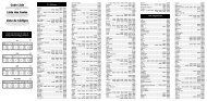
6. When you have identified the correct resistance use the chart on page 4<br />
to set the resistance on the bypass module. Locate the closest value<br />
which is less than your desired value. Set dip-switches 2 through 6 to<br />
match the chart on page 4.<br />
7. Put your ohm meter (multi-meter) probes on the two silver resistance<br />
measuring pads through the opening shown in the drawing -- making<br />
good contact with these two silver pads on the board. (See drawing on<br />
page 1). Or put your two probes into the two holes on the bottom of the<br />
case making contact with the underside of the silver pads. Either contact<br />
point method will work.<br />
8. With the probes held firmly -- dial-in the final resistance value needed for<br />
your system by turning the screw on the variable resistor on the side of<br />
the unit next to the dip switches. Turn the screw until the resistance<br />
value matches the resistance value of the key.<br />
9. Connect the bypass module using the diagram on the next page. Be<br />
sure to tape over any connections to not leave any exposed wires.<br />
V 0.3 7 ASPASSIII