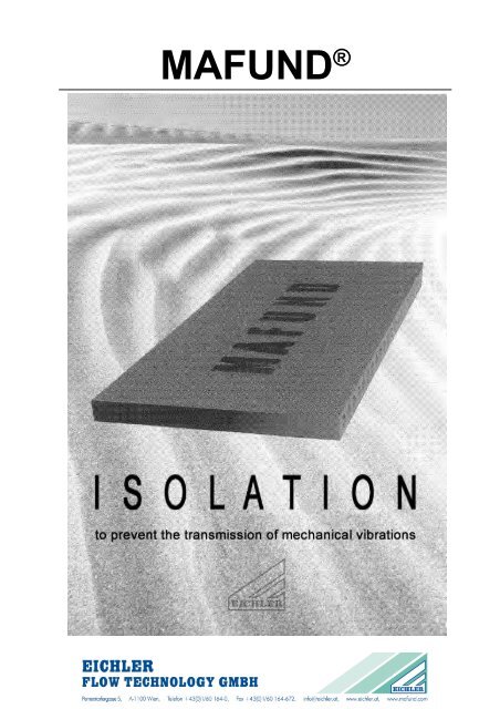
MAFUND®
MAFUND®
MAFUND®

You also want an ePaper? Increase the reach of your titles
YUMPU automatically turns print PDFs into web optimized ePapers that Google loves.
MAFUND ®
PREFACE<br />
MAFUND ®<br />
Machines and contrivances with moved pads<br />
cause mechanical vibrations. The effects on<br />
the installing place and its surroundings are<br />
shocks and conduction of sound. In order to<br />
prevent the transmission of vibrations to the<br />
floor and within to the building, an efficient<br />
vibration isolation must be mounted between<br />
machines respectively apparatuses or their<br />
foundations and the installing floor. In this<br />
case we speak about<br />
ACTIVE Isolation<br />
The Active Isolation is provided because of<br />
environment protection<br />
GENERAL MATTERS<br />
For many years the MAFUND ® -Pad (Fig. 1)<br />
has been mounted under machines,<br />
equipments constructions and the like. or<br />
under their foundations, as a protection<br />
against shocks, vibrations and noise. Our<br />
practice and technical development on the<br />
material sector being of longstanding, the<br />
MAFUND ® -Pad has been improved<br />
continually. Consequently it corresponds to<br />
the newest state of engineering. The<br />
approved form and the dimensions are<br />
unchanged.<br />
Fig. 1<br />
Elevator engine of Ringturm, Vienna<br />
protection of the building<br />
protection of the machines and, as a<br />
consequence, longer durability.<br />
To protect precision machines and equipment,<br />
measuring instruments and the like from shocks<br />
and vibrations coming from the environment, a<br />
corresponding Isolation must be likewise<br />
installed. Here we have to do with a<br />
PASSIVE Isolation<br />
The MAFUND ® -Pad can be used In wide fields<br />
for the Active as well as for the passive-Isolation.<br />
MAFUND ® - Pad<br />
Fig. 2<br />
<strong>MAFUND®</strong>-Pad<br />
Dimensions: 500 x 250 x 25 mm<br />
Beside the outstanding technical qualities such as<br />
springing, damping, a practically permanent<br />
resistance to ageing and chemical influences,<br />
insects and so on, the <strong>MAFUND®</strong>-Pad offers<br />
operating technical advantages due to the<br />
standardized dimensions and the structurally<br />
uniform shape.<br />
Owing to the quoted qualities a maximum<br />
isolation effect accompanied by a remarkably low<br />
overall height is attained.<br />
Modern challenges, especially in the combat<br />
against the operating noise in its various shapes,<br />
provide wide possibilities for the economic use of<br />
the <strong>MAFUND®</strong>-Pad. Several application territories<br />
are mentioned as follows.<br />
machines of every category<br />
contrivances<br />
furnaces<br />
air conditioning units<br />
heavy structures<br />
conveying plants<br />
supports of pipelines<br />
railway and undergrund rails
TECHNICAL DATA<br />
Dimensions: 500 x 250 x 25 mm<br />
Load: 2-20 N/cm² ≈ 0,2-2 kp/cm²<br />
in special cases<br />
40 N/cm² ≈ 4 kp/cm²<br />
TECHNICAL MATTERS<br />
The <strong>MAFUND®</strong>-Pad consists of a<br />
permanently resistant elastic special material<br />
with correspondingly proportioned air ducts.<br />
The dimensioning of the <strong>MAFUND®</strong>-Pad<br />
depends on the excitation frequency to be<br />
isolated. The diagram in Fig. 4 gives<br />
information about the resonant frequencies of<br />
the <strong>MAFUND®</strong>-Pad in dependence on the<br />
specific loading pressure. It shows relatively<br />
low resonant frequencies under various<br />
loadings. That is the reason why the<br />
<strong>MAFUND®</strong>-Pad is useable for a wide range of<br />
excitation frequencies.<br />
The relation between frequency ratio<br />
L=/f o - (f = excitation frequency, f o = resonant<br />
frequency) - and the degree of isolation is<br />
shown in Fig. 5 It is evident, that an isolation<br />
effect occurs only starting from a tuning ratio<br />
f/f o > 2. In this case we speak of an<br />
"overcritical" support.<br />
In case of an "undercritical" support -<br />
f/f o < 2 - there is no isolation effect for the<br />
basic frequency - number of revolutions of the<br />
machine - to be expected. As the sound<br />
frequencies are mostly much higher than the<br />
basic frequency - number of oscillatory Im<br />
pulses = excitation frequency - it is obvious.<br />
that also in case of "undercritical" support a<br />
good noise isolation can be obtained. If we<br />
consider, that forces and momentums due to<br />
the mass cause a great number of harmonic<br />
vibrations, it is explicable that even in case of<br />
an "undercritical" support a isolation effect is<br />
achieved, because thus amplitudes of the<br />
excitation frequencies, so to peak, are cut off.<br />
MAFUND ®<br />
Static module of<br />
elasticity: E st = 324 N/cm² ≈ 33 kp/cm²<br />
Dynamic module of<br />
elasticity: E d = 441 N/cm² ≈ 45 kp/cm²<br />
Springing: see Load deflection curve Fig.3<br />
Resonant frequency: see curves Fig. 4<br />
Temperature range: -20°C to +80°C<br />
Standard weight: ≈ 3 kp<br />
1 Newton (N) = 0,102 kp<br />
Fig. 3<br />
Load deflection curve of the <strong>MAFUND®</strong>-Pad<br />
Deflection in mm<br />
5<br />
4,5<br />
4<br />
3,5<br />
3<br />
2,5<br />
2<br />
1,5<br />
1<br />
0,5<br />
5 10 15 20 25 30 35 40 45 50<br />
Fig. 4<br />
Resonant frequencies of the <strong>MAFUND®</strong>-Pad<br />
Resonant frequency f o in Hz<br />
24<br />
23<br />
22<br />
21<br />
20<br />
19<br />
18<br />
17<br />
16<br />
15<br />
14<br />
13<br />
12<br />
11<br />
1 Layer<br />
10<br />
9<br />
8<br />
2 Layer<br />
7<br />
3 Layer<br />
6<br />
5<br />
4<br />
4 Layer<br />
3<br />
2<br />
1<br />
0 5 10 15 20 25 30 35 40 45 50 55 60<br />
Loading in N/cm²<br />
Fig. 5<br />
Degree of isolation in dependence to the<br />
relation of frequencies<br />
Oscillation isolation (dB)<br />
25<br />
24<br />
23<br />
22<br />
21<br />
20<br />
19<br />
18<br />
17<br />
16<br />
15<br />
14<br />
13<br />
12<br />
11<br />
10<br />
9<br />
8<br />
7<br />
6<br />
5<br />
4<br />
3<br />
2<br />
1<br />
1,5 1,7 1,9 2,2 2,6 3 3,5 4 4,5 5 6 7<br />
Ratio of frequencies λ = f<br />
f o<br />
94,4<br />
93,7<br />
93<br />
92<br />
91<br />
90<br />
89<br />
87,5<br />
86<br />
84<br />
82<br />
80<br />
78<br />
75<br />
72<br />
68<br />
64<br />
60<br />
55<br />
50<br />
44<br />
37<br />
29<br />
21<br />
11<br />
Degree of isolation (%)
MOUNTING<br />
The mounting of the <strong>MAFUND®</strong>-Pads has to<br />
ensure regarding to vibration technical<br />
considerations. The <strong>MAFUND®</strong>-Pads can be laid<br />
in form of both whole pads and in form of cuttings.<br />
Smaller cuttings than 125 x 125 mm should not be<br />
used for installation. The cutting is possible with a<br />
sharp knife or a band saw and can be done on the<br />
mounting place.<br />
MOUNTING EXAMPLES<br />
<strong>MAFUND®</strong>-Isolation under a sunken<br />
foundation Fig. 6<br />
In a correspondingly dimensioned concrete tub the<br />
<strong>MAFUND®</strong>-Pads are arranged either throughout or<br />
in area parts. In case of arrangement in area parts<br />
the intervals have to be filled up with scum in<br />
material. Then the complete area is covered by e<br />
tarboard in order to prevent the fluid concrete from<br />
getting into the slits between the <strong>MAFUND®</strong>-Pads<br />
and consequently originating a sound bridge. One<br />
has to bear In mind that the first concrete layer is<br />
responsible for an equal loading and in case of an<br />
area part arrangement, the first layer of fluid<br />
concrete has to be put in symmetrically, in order to<br />
prevent pressed down and hard fill-up layers.<br />
Along the circumference of the foundation it is<br />
possible to incorporate air slits or <strong>MAFUND®</strong>-Pads<br />
between foundation and the concrete tub. The<br />
coverings of these slits are to be elastic.<br />
Fig. 6<br />
Sunken foundation mounted on <strong>MAFUND®</strong>-Pads<br />
Air slit<br />
<strong>MAFUND®</strong>-Pads<br />
MAFUND ®<br />
Elasic<br />
ledge<br />
If there are greater basic areas. the whole pads are<br />
arranged along the circumference and then the<br />
middle areas will be filled corespondently<br />
Fundamentally the MAFUNO®-Pads are to be<br />
installed in a manner, that there is no rigid<br />
connection between the machine and the<br />
foundation. Rigid connections are noise bridges,<br />
vibrations are transmitted via these and therefore<br />
the effect of the isolation is reduced. Pipelines,<br />
which mounted on the machines are to be isolated<br />
against transmission of vibrations.<br />
Fig. 7<br />
Turbo generator power plant Suratthani,<br />
Thailand<br />
Fig. 8<br />
Roll grindig machine<br />
machines factory J. M. Voith
<strong>MAFUND®</strong>-Isolation<br />
under a concrete distribution plate<br />
Fig. 9<br />
The <strong>MAFUND®</strong>-Pads are mounted under a<br />
foundation or a distribution plate made of<br />
concrete - steel and wood distribution plates are<br />
possible too. Only distortion resistant machines<br />
with corresponding supporting areas, without<br />
free forces and momentums due to the mass,<br />
can be installed directly on an oscillation<br />
isolation.<br />
Fig. 9<br />
<strong>MAFUND®</strong>-Pads under a machine with<br />
concrete distribution plate<br />
<strong>MAFUND®</strong>-Pads<br />
Fig. 10<br />
Compressors "Red Cross", Bern<br />
MAFUND ®<br />
Concrete<br />
distribution<br />
plate<br />
Fig. 11<br />
Emergency generator<br />
Fig. 12<br />
Newspaper printing machine<br />
KOEBAU "Courier 25", "Kurier" Vienna
<strong>MAFUND®</strong>-Isolation<br />
under a concrete foundation with area parts<br />
installation Fig. 13<br />
The kind of mounting is the same as in Fig. 9<br />
shown, but the area parts installation ensued in<br />
double layer construction of <strong>MAFUND®</strong>-Pads.<br />
Fig. 13<br />
Machine roundation on a double layer of<br />
<strong>MAFUND®</strong>-Pads<br />
Concrete distribution plate<br />
<strong>MAFUND®</strong>-Pads<br />
<strong>MAFUND®</strong>-Isolation under a concrete fundation<br />
with side fixation - Fig. 15<br />
If there is an influence of horizontally operating<br />
forces to the machine, it is appropiated to make<br />
precautions against lateral gliding of the concrete<br />
plate. This installing type shows a possible<br />
solution.<br />
MAFUND ®<br />
Fig. 14<br />
Chocolate calender<br />
Fig. 15<br />
Machine foundation with lateral<br />
fixation on <strong>MAFUND®</strong>-Pads<br />
Concrete<br />
distribution<br />
plate<br />
<strong>MAFUND®</strong>-Pads Fixations of the foundation plate<br />
against lateral gliding
<strong>MAFUND®</strong>-Isolation<br />
under distribution plate with pressure systems<br />
Fig. 16<br />
<strong>MAFUND®</strong>-Pads are laid under a steel distribution<br />
plate. This plate is anchored elastically. The screws<br />
receive <strong>MAFUND®</strong> shims and have to pass barely<br />
through the distribution plate. The machine itself is<br />
bolted on the distribution plate.<br />
Fig. 16<br />
Machine with distribution plate on<br />
<strong>MAFUND®</strong>-Pads<br />
Pressure system<br />
<strong>MAFUND®</strong>-Pads<br />
<strong>MAFUND®</strong>-Isolation directly under the machine -<br />
Fig. 18<br />
Only in rate cases the <strong>MAFUND®</strong>-Pads are<br />
installed directly - without foundation, distribution<br />
plate and so on - under machine<br />
MAFUND ®<br />
Distribution plate<br />
made of steel<br />
Fig. 17<br />
Eccentric press<br />
Fig. 18<br />
Jet moulding machine for synthetic material
There are support cases in practice, where there<br />
appear extremely specific loading pressures on<br />
the isolation to be installed. When, for example,<br />
machines are mounted on grider grillages -<br />
isolation of the machine on the griders, isolation<br />
of the griders in the masonry - or even in the<br />
industry of building. For this the <strong>MAFUND®</strong>-<br />
Solid-Pad (Fig. 19) has been created.<br />
Fig. 19<br />
<strong>MAFUND®</strong>-Solid-Pad<br />
Dimensions: 500 x 250 x 15 mm<br />
MAFUND ®<br />
MAFUND ® -Solid-Pad<br />
The external dimensions of the <strong>MAFUND®</strong>-Solid-<br />
Pad are 500x250x15mm. Standard weight is<br />
about 2,2kp.<br />
Fig. 20 shows the load deflection curve of the<br />
<strong>MAFUND®</strong>-Solid-Pad.<br />
This bearing pad can be loaded up to 200 N/cm² -<br />
20 kp/cm²<br />
Fig. 20<br />
Load deflection curve of the<br />
<strong>MAFUND®</strong>-Solid-Pad<br />
Deflection in mm<br />
2<br />
1,5<br />
1<br />
0,5<br />
20 40 60 80 100 120 140 160<br />
Loading in N/cm²