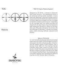
Compact NXS ZeroStop and Windage Limiter ... - SportOptics
Compact NXS ZeroStop and Windage Limiter ... - SportOptics
Compact NXS ZeroStop and Windage Limiter ... - SportOptics

You also want an ePaper? Increase the reach of your titles
YUMPU automatically turns print PDFs into web optimized ePapers that Google loves.
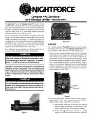
ecause the stop position is ½ turn away from the<br />
zero position. See Figure 3.<br />
3. With the turrets in the “0” position, apply downward pressure<br />
on the turret <strong>and</strong> tighten the set screw to 5 inch pounds. See<br />
Figure 2 <strong>and</strong> 3.<br />
Your riflescope is now ready for use. If you change the load you<br />
may need to go through the zeroing process again to adjust for<br />
the new trajectory.<br />
2.5-10x <strong>NXS</strong><br />
The 2.5-10 <strong>NXS</strong> elevation <strong>ZeroStop</strong> allows full use of the available<br />
up elevation travel for longer target engagement distances.<br />
The <strong>Windage</strong> <strong>Limiter</strong> allows ½ of a revolution in either<br />
direction from the established zero position.<br />
Note: The O-rings inside the turret assembly <strong>and</strong> under the<br />
turret set screw must remain in place <strong>and</strong> must be lubricated<br />
in order to maintain the waterproof integrity of the riflescope.<br />
1. Use the elevation <strong>and</strong> windage turrets to zero the riflescope<br />
at the desired range. If you need additional down travel for<br />
the elevation turret see 2.5-10x <strong>NXS</strong> step 2. To obtain additional<br />
windage turret travel, see 2.5-10x <strong>NXS</strong> step 4.<br />
2. Remove the elevation turret by loosening the set screw 1 ¼<br />
turns <strong>and</strong> remove it by turning it clockwise <strong>and</strong> lifting upward.<br />
See Figure 2.<br />
2. Loosen the setscrew on the elevation <strong>ZeroStop</strong> clutch assembly<br />
1½ turns <strong>and</strong> reinstall the elevation turret, leaving<br />
the <strong>ZeroStop</strong> clutch assembly set screw loose. Tighten the<br />
elevation turrett set screw to 5 inch pounds. See Figure 4<br />
<strong>and</strong> Figure 2.<br />
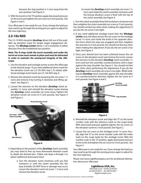
Zero-Stop<br />
Clutch Assembly<br />
Allen Wrench<br />
Bronze Elevation Screw<br />
Figure 4<br />
3 Depending on the position of the <strong>ZeroStop</strong> clutch assembly,<br />
you may need to free up more downward elevation travel<br />
to obtain the desired zero. Follow sub steps a through c to<br />
obtain additional downward travel.<br />
a. Turn the elevation turret clockwise until you feel<br />
resistance or until the clutch assembly hits the<br />
stop shoulder. Do NOT force or damage may occur.<br />
Loosen the elevation turret set screw 1 ¼ turns <strong>and</strong><br />
remove the elevation turret.<br />
<strong>Compact</strong> <strong>NXS</strong> <strong>ZeroStop</strong> <strong>and</strong> <strong>Windage</strong> <strong>Limiter</strong> Instructions - Revision 25JAN2008<br />
b. Loosen the <strong>ZeroStop</strong> clutch assembly set screw 1 ½<br />
turns <strong>and</strong> rotate the clutch assembly clockwise until<br />
the bronze elevation screw is flush with the top of<br />
the clutch assembly. See Figure 4.<br />
c. Turn the clutch assembly three full revolutions clockwise <strong>and</strong><br />
then retighten the clutch assembly set screw to 5 inch pounds.<br />
You should not feel any clicks when making this adjustment. If<br />
you do, the set screw is too tight.<br />
4. If you need additional windage travel than the <strong>Windage</strong><br />
<strong>Limiter</strong> stop will allow, loosen the set screw on the windage<br />
turret 1¼ turns <strong>and</strong> rotate the knob in the opposite direction<br />
from which the stop was engaged, <strong>and</strong> then retighten<br />
the setscrew to 5 inch pounds. You should not feel any clicks<br />
when making this adjustment. If you do, the set screw is too<br />
tight. See Figure 3.<br />
5. Once your desired zero has been achieved, loosen the set<br />
screw on the elevation turret <strong>and</strong> remove the turret. Loosen<br />
the setscrew on the elevation <strong>ZeroStop</strong> clutch assembly 1 ½<br />
turns <strong>and</strong> turn the assembly counterclockwise until it stops<br />
against the stop shoulder. See Figure 5. You should not feel<br />
any clicks when performing this adjustment. If you do the<br />
<strong>ZeroStop</strong> clutch assembly set screw is too tight. While holding<br />
the <strong>ZeroStop</strong> clutch assembly against the stop shoulder<br />
in a counterclockwise direction, tighten the set screw to 5<br />
inch pounds. See Figure 4 <strong>and</strong> 5.<br />
Figure 5<br />
6. Reinstall the elevation turret <strong>and</strong> align the “0” on the turret<br />
number scale with the reference mark on the scope body.<br />
With downward pressure applied, tighten the set screw on<br />
the elevation turret to 5 inch pounds. See Figure 2.<br />
7. Loosen the set screw on the windage turret 1¼ turns. Visually<br />
align the “0” on the turret number scale with the index<br />
mark on the scope body for the windage turret. With the<br />
number scale in the “0” position, apply downward pressure<br />
to the turret <strong>and</strong> tighten the set screw to 5 inch pounds. See<br />
Figure 3.<br />
Your riflescope is now ready for use. If you change the load you<br />
may need to go through the zeroing process again to adjust for<br />
the new trajectory.<br />
Please visit www.nightforceoptics.com for ad ditional information<br />
about your riflescope.<br />
Lightforce USA, Inc.<br />
1040 Hazen Lane - Orofino, ID 83544<br />
tel 208.476.9814 - fax 208.476.9817<br />
NightforceOptics.com<br />
<strong>ZeroStop</strong><br />
Clutch Assembly<br />
Stop Shoulder