Center for Nuclear Study,
Center for Nuclear Study,
Center for Nuclear Study,

Create successful ePaper yourself
Turn your PDF publications into a flip-book with our unique Google optimized e-Paper software.
Per<strong>for</strong>mance of LP-MWDC <strong>for</strong> � beam at 35.2 MeV<br />
H. Miyaa , S. Shimourab , A. Saitoc , T. Kawabatab , H. Kureib , S. Michimasab , K. Mikic ,<br />
K. Nakanishib , S. Otab , Y. Sasamotob , T. Uesakab and H. Sakaic aDepartment of Physics, Rikkyo University<br />
b<strong>Center</strong> <strong>for</strong> <strong>Nuclear</strong> <strong>Study</strong>, Graduate School of Science, University of Tokyo<br />
cDepartment of Physics, University of Tokyo<br />
1. Introduction<br />
We are developing Low-Pressure Multi-Wire Drift<br />
Chambers with stripped cathodes and delay-line readouts<br />
(LP-MWDCs) as tracking detectors [1], which will be used<br />
in the SHARAQ beam line under construction at RIBF<br />
[2, 3]. The LP-MWDC has characteristics that positions<br />
of beam particles are determined with signals from anode<br />
wires and cathodes, and the chamber gas is operated at the<br />
low pressure of less than 20 kPa to reduce the effect of the<br />
multiple scattering. Figure 1 shows a schematic structure<br />
of the LP-MWDC. The strips of the cathode (CX, CY) are<br />
connected to delay lines [4]. The anode plane (AX, AY)<br />
consists of 16 anode wires and 17 potential wires. The LP-<br />
MWDC has outputs of 2 cathodes and 32 anode wires.<br />
Cathode(CY)<br />
Anode (AX)<br />
Cathode<br />
Cathode<br />
-HV<br />
Anode (AY)<br />
-HV<br />
-HV<br />
Cathode (CX)<br />
96mm<br />
-HV<br />
96mm<br />
-HV<br />
Potential wire<br />
Anode wire<br />
Figure 1. A schematic structure of the LP-MWDC with stripped<br />
cathodes and delay-line readouts.<br />
In March 2008, we per<strong>for</strong>med a test experiment to<br />
study per<strong>for</strong>mances of the LP-MWDC <strong>for</strong> an � beam at<br />
35.2 MeV. Here, we report basic characteristics of the LP-<br />
MWDC, derived from on-line analysis.<br />
2. Experiment<br />
The test experiment was per<strong>for</strong>med at E7B course in<br />
RIKEN RIBF operated by RIKEN Nishina <strong>Center</strong> and<br />
CNS, University of Tokyo. � An beam at 35.2 MeV was<br />
supplied by the AVF cyclotron accelerator. The energy deposition<br />
of � the beam in the LP-MWDC is comparable to<br />
�£� a N beam 200� at MeV, which is a candidate <strong>for</strong> the first<br />
experiment to be per<strong>for</strong>med with the SHARAQ. Figure 2<br />
shows a schematic view of the experimental setup. A plastic<br />
scintillator with the size 50� of mm� 50 and the thickness<br />
of 5 mm was used as a trigger counter. The LP-MWDC was<br />
operated using an isobutane gas (i– � � ) at 4, 5, 10, 15<br />
and 20 kPa. The timings from the anodes and the cathodes,<br />
�����<br />
and the pulse heights from the cathodes were measured.<br />
-HV<br />
60<br />
α Beam<br />
Gate valve<br />
Al, ZnS<br />
Vacuum Chamber<br />
LP-MWDC<br />
Plastic Scint.<br />
Light Guide<br />
PMT<br />
Figure 2. A schematic view of the experimental setup.<br />
The data of these timings and pulse heights were taken with<br />
CAEN V1190A multi-hit TDC and CAEN V792N QDC,<br />
respectively.<br />
3. Results<br />
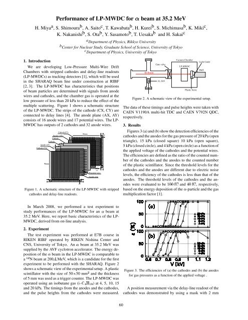
Figures 3 (a) and (b) show the detection efficiencies of the<br />
cathodes and the anodes <strong>for</strong> the gas pressure of 20 kPa (open<br />
triangle), 15 kPa (closed square) 10 kPa (open square),<br />
5 kPa (closed circle), and 4 kPa (open circle) as a function of<br />
the applied voltage of the cathodes and the potential wires.<br />
The efficiencies are defined as the ratio of the counted number<br />
of the cathodes and the anodes to the counted number<br />
of the plastic scintillator. Since the threshold levels <strong>for</strong> the<br />
cathodes and the anodes are different due to electric noise<br />
levels, the efficiency of the cathodes is less than that of the<br />
anodes. The threshold levels of the cathodes and the an-<br />
odes were evaluated to be �����<br />
���<br />
and ���<br />
���<br />
, respectively,<br />
based on the energy deposition of the � -particle and the gas<br />
multiplication factor [1].<br />
Figure 3. The efficiencies of (a) the cathodes and (b) the anodes<br />
<strong>for</strong> gas pressures as a function of the applied voltage .<br />
A position measurement via the delay-line readout of the<br />
cathodes was demonstrated by using a mask with 2 mm