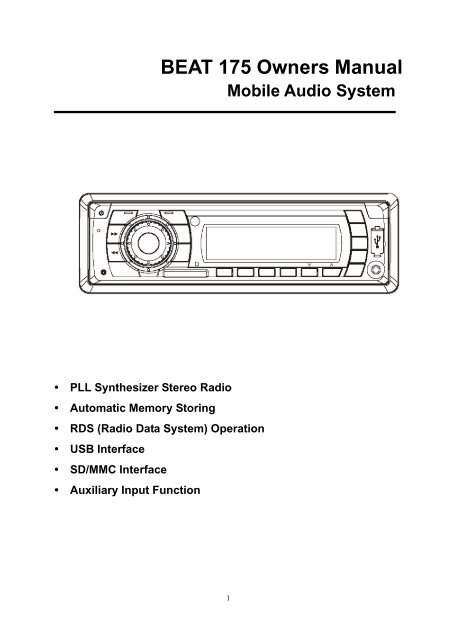
BEAT 175 Owners Manual - Connects2
BEAT 175 Owners Manual - Connects2
BEAT 175 Owners Manual - Connects2

You also want an ePaper? Increase the reach of your titles
YUMPU automatically turns print PDFs into web optimized ePapers that Google loves.
� PLL Synthesizer Stereo Radio<br />
� Automatic Memory Storing<br />
<strong>BEAT</strong> <strong>175</strong> <strong>Owners</strong> <strong>Manual</strong><br />
Mobile Audio System<br />
� RDS (Radio Data System) Operation<br />
� USB Interface<br />
� SD/MMC Interface<br />
� Auxiliary Input Function<br />
1
CONTENTS<br />
Installation...........................................3<br />
Take out screw before installation.........3<br />
DIN Front-Mount (Method A).................3<br />
Installing the unit ...............................3<br />
Removing the unit .............................4<br />
DIN Rear-Mount (Method B) .................4<br />
Wiring Connection..............................6<br />
Operation.............................................9<br />
General operation .................................7<br />
Switching on/off the unit ......................7<br />
Sound adjustment ...............................7<br />
Loudness ............................................7<br />
Display information .............................8<br />
Liquid Crystal Display..........................8<br />
Remote sensor (Optional) ...................9<br />
Auxiliary input......................................9<br />
Radio operation ....................................9<br />
Switching to radio mode....................9<br />
Selecting the frequency band............9<br />
Selecting station................................9<br />
2<br />
Automatic memory storing&<br />
program scanning ............................. 9<br />
Station storing ................................... 9<br />
RDS (radio data system) operation... 9<br />
USB play operation............................... 11<br />
Supported MP3/WMA decoding modes<br />
............................................................. 11<br />
SD/MMC operation ............................... 11<br />
Specification ....................................... 12<br />
Trouble shooting ................................ 12
INSTALLATION<br />
screwdriver. Not all tabs will be able to<br />
make contact, so examine which ones<br />
will be most effective. Bending open the<br />
appropriate tabs behind the dashboard<br />
to secure the sleeve in place.<br />
Screwdriver<br />
Tabs<br />
Dashboard<br />
Sleeve<br />
6. Reconnect the wire harness and the<br />
antenna and be careful not to pinch any<br />
wires or cables.<br />
7. Slide the unit into the sleeve until it<br />
locks into place.<br />
8. To further secure the unit, use the<br />
supplied metal strap to secure the back<br />
of the unit in place. Use the supplied<br />
hardware (Hex Nut (M5mm) and Spring<br />
Washer) to attach one end of the strap<br />
to the mounting bolt on the back of the<br />
unit. If necessary, bend the metal strap<br />
to fit your vehicle’s mounting area. Then<br />
use the supplied hardware (Tapping<br />
Screw (5x25mm) and Plain Washer) to<br />
attach the other end of metal strap to a<br />
solid metal part of the vehicle under the<br />
dashboard. This strap also helps ensure<br />
proper electrical grounding of the unit.<br />
Note to install the short threading<br />
terminal of the mounting bolt to the back<br />
of the unit and the other long threading<br />
terminal to the dashboard.<br />
4<br />
Metal Strap<br />
Mounting Bolt<br />
Spring Washer Hex Nut<br />
Plain Washer<br />
Tapping Screw<br />
9. Reconnect the cable to the vehicle<br />
battery’s negative (-) terminal. Then<br />
replace the outer trim ring.<br />
Removing the unit<br />
1. Make sure the ignition is turned off, then<br />
disconnect the cable from the vehicle<br />
battery’s negative (-) terminal.<br />
2. Remove the metal strap attached the<br />
back of the unit (if attached).<br />
3. Lift the top of the outer trim ring then pull<br />
it out to remove it.<br />
4. Insert both of the supplied keys into the<br />
slots at the middle left and right sides of<br />
the unit, then pull the unit out of the<br />
dashboard.<br />
DIN REAR-MOUNT (Method B)<br />
If your vehicle is a Nissan, Toyota, follow<br />
these mounting instructions.<br />
Use the screw holes marked T (Toyota), N<br />
(Nissan) located on both sides of the unit to<br />
fasten the unit to the factory radio mounting<br />
brackets supplied with your vehicle.
INSTALLATION<br />
Screw<br />
Hook<br />
Side View showing<br />
T, N<br />
Screw<br />
Dashboard or Console<br />
To fasten the unit to the factory radio<br />
mounting brackets.<br />
1. Use a screwdriver to loose the hook’s<br />
screws on the front left and right sides<br />
of the unit and remove the hooks.<br />
2. Align the screw holes on the bracket<br />
with the screw holes on the unit, and<br />
then tighten the screws (5x5mm) on<br />
each side.<br />
Note: the outer trim ring, sleeve and the<br />
metal strap are not used for method B<br />
installation.<br />
5
WIRING CONNECTION<br />
6
OPERATION<br />
When newly tuned station has not<br />
RDS signal, “PI SEEK” is<br />
suppressed somewhat.<br />
b) PI SOUND or PI MUTE<br />
While AF switching is implemented in<br />
C201 station, AF can switch to 100<br />
MHz, which is non genuine AF (where,<br />
different PI with same AF) in short<br />
“DIP”.<br />
If a car cruises that critical area back<br />
and forth, an oscillation<br />
phenomenon can be occurred,<br />
because the different PI code can be<br />
received from 100 MHz with “XXX” PI.<br />
The car radio has special procedure<br />
to reduce even this kind of<br />
unavoidable situation however there<br />
is a limit to be escaped from this<br />
serious case perfectly.<br />
In that serious case, 2 mode is<br />
selectable as follows:<br />
100<br />
98<br />
90<br />
100<br />
PI: C201 PI: XXX<br />
- PI SOUND mode:<br />
When above different PI sound (DIP)<br />
is heard once in a while, the DIP’s<br />
sound will be heard for a short time.<br />
- PI MUTE mode:<br />
Under above same situation, a mute<br />
sound will be heard for a short time.<br />
c) RETUNE L or RETUNE S mode<br />
The initial time of automatic TA search<br />
or PI search modes is selected.<br />
When PI information is not caught for<br />
retune time, the radio starts to retune<br />
to next same PI station.<br />
When same PI station does not catch<br />
1 cyclic search, the radio goes to last<br />
station and waits for several minutes<br />
until PI code is received.<br />
- RETUNE L mode:<br />
Selected as 90 seconds.<br />
8<br />
- RETUNE S mode:<br />
Selected as 30 seconds.<br />
d) MASK DPI or MASK ALL mode<br />
The AF frequency (which has different<br />
PI or NO RDS signal with high field<br />
strength) is masked during checking<br />
PI when the unit searches AF. The<br />
unit doesn’t search this AF (DIP) for<br />
few minutes. In the case of the AF of<br />
NO RDS signal with high field<br />
strength, if the real AF is wrongly<br />
masked as DIP by some interference,<br />
the unit hesitates to search real Afs.<br />
For this reason, the unit has the user<br />
option (MASK DPI) which doesn’t<br />
mask the AF of NO RDS signal with<br />
high field strength. In MASK DPI<br />
mode, the wrong sound or long mute<br />
(according to PI SOUND or PI MUTE)<br />
can be heard from the AF station<br />
which has NO RDS signal and of<br />
which the field strength is higher than<br />
that of the currently tuning AF (station).<br />
But, these phenomenons are rare and<br />
the user will hardly hear the wrong<br />
sound in whole Europe.<br />
- MASK DPI mode:<br />
Masked only the AF which has<br />
different PI.<br />
- MASK ALL mode:<br />
Masked the AF which has different<br />
PI and NO RDS signal with high<br />
field strength.<br />
e) BEEP<br />
ON/OFF mode<br />
- BEEP ON<br />
The beep is generated when every<br />
key is pressed.<br />
- BEEP OFF mode:<br />
The beep is disabled.<br />
DISPLAY INFORMATION<br />
- Press DISP button (9) to show the time.<br />
LIQUID CRYSTAL DISPLAY<br />
Exhibit current frequency and activated<br />
functions on the display (6).
OPERATION<br />
REMOTE SENSOR (OPTIONAL)<br />
Point the remote control handset to the<br />
remote sensor IR (5). Press the function<br />
keys on the handset to control the system.<br />
AUXILIARY INPUT<br />
The unit can be connected to a portable<br />
audio player through the AUX IN jack (13).<br />
USB INTERFACE<br />
On the front panel of the unit, there is an<br />
USB interface (12). You can connect an<br />
USB driver through this interface (12).<br />
RADIO OPERATION<br />
SWITCHING TO RADIO MODE<br />
Press MODE button (11) shortly to select<br />
radio mode, the radio mode appears in the<br />
display together with the memory band and<br />
frequency.<br />
SELECTING THE FREQUENCY BAND<br />
At radio mode, press BND/LOU/ENT<br />
button (4) shortly to select the desired<br />
band.<br />
The reception band will change in the<br />
following order:<br />
FM1 FM2 FM3 MW1 MW2<br />
SELECTING STATION<br />
Press button (2) or button (24)<br />
shortly to activate automatic seek function.<br />
Press for several seconds until “MANUAL”<br />
appears on the display, the manual tuning<br />
mode is selected. If both buttons have not<br />
been pressed for several seconds, they will<br />
return to seek tuning mode and “AUTO”<br />
appears on the display.<br />
AUTOMATIC MEMORY STORING &<br />
PROGRAM SCANNING<br />
- Automatic memory storing<br />
Press AS/PS button (10) for several<br />
seconds, the radio searches from the<br />
current frequency and checks the signal<br />
9<br />
strength until one cycle search is finished.<br />
And then the strongest stations are<br />
stored into the corresponding preset<br />
number button.<br />
- Program scanning<br />
Press AS/PS button (10) shortly to scan<br />
preset station. When the field strength<br />
level is more than the threshold level of<br />
stop level, the radio is holding at that<br />
preset number for several seconds with<br />
release mute, then searches again.<br />
STATION STORING<br />
Press any one of the preset buttons (18) (1<br />
to 6) to select a station, which had been<br />
stored in the memory. Press this button for<br />
several seconds, current station is stored<br />
into the number button.<br />
RDS FUNCTION<br />
1. AF<br />
AF / REG<br />
- AF / REG key directs the activation of<br />
AF SEARCH.<br />
- AF indicator is displayed when AF is<br />
ON, AF search is activated when<br />
reception is bad.<br />
- During FM MODE,when AF is ON,<br />
SEEK, SCAN, AUTO, MEMORY<br />
function can only receive and save.<br />
2. TA<br />
- TA is turned ON / OFF and TA indicator<br />
is displayed.<br />
When traffic announcement is<br />
transmitted, regardless of the mode,<br />
traffic announcement is received.<br />
- when TA is on, SEEK,SCAN, AUTO<br />
MEMORY function can be received or<br />
saved or saved only when traffic<br />
program identification code has been<br />
received.<br />
- When TA is ON, traffic program<br />
identification code is not received<br />
during specified time. TA ALARM : NO<br />
TA / TP is displayed and alarm is set off.
TROUBLE SHOOTING<br />
Before going through the checklist, check wiring connection. If any of the problems<br />
persist after checklist has been made, consult your nearest service dealer.<br />
Symptom Cause Solution<br />
No power.<br />
No sound.<br />
The operation<br />
keys do not<br />
work.<br />
The radio does<br />
not Work. The<br />
radio station<br />
automatic<br />
selection does<br />
not work.<br />
The car ignition switch is<br />
not on.<br />
If the power supply is<br />
connected to the car accessory<br />
circuits, but the engine is not<br />
moving, switch the ignition key<br />
to “ACC”.<br />
The fuse is blown. Replace the fuse.<br />
Volume is in minimum Adjust volume to a desired level.<br />
Wiring is not properly<br />
connected.<br />
The built-in microcomputer<br />
is not operating properly<br />
due to noise.<br />
The antenna cable is not<br />
connected.<br />
Check wiring connection.<br />
Press the reset button.<br />
Insert the antenna cable firmly.<br />
The signals are too weak. Select a station manually.<br />
13