
Create successful ePaper yourself
Turn your PDF publications into a flip-book with our unique Google optimized e-Paper software.
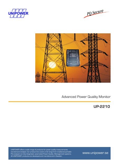
UNIPOWER offers a wide range of products for power quality measurements<br />
and demand analysis. Our product line covers a full range from traditional portable<br />
PQ analysers to fully integrated, automated Power Quality Management systems.<br />
All UNIPOWER products are developed and manufactured in Sweden.<br />
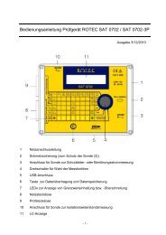
Advanced Power Quality Monitor<br />
<strong>UP</strong>-<strong>2210</strong><br />
www.unipower.se
<strong>UP</strong>-<strong>2210</strong><br />
Advanced 3-phase<br />
Power Quality and<br />
Transient Monitor<br />
� Norm-compliant,<br />
IEC 61000-4-30 Class A<br />
� Power Quality Monitoring<br />
� Transient Monitoring<br />
� Demand Monitoring<br />
� Fault Recorder<br />
� GPS Synchronisation<br />
� Fully Simultaneous Operation<br />
The <strong>UP</strong>-<strong>2210</strong> Power Quality Monitor is designed for<br />
permanent installation in any 50 / 60 Hz system. All<br />
voltage and current channels are differential, allowing<br />
the <strong>UP</strong>-<strong>2210</strong> to be installed regardless of system<br />
configuration.<br />
The unit has 12 voltage and 4 current channels which<br />
may either be connected directly or using PTs and CTs<br />
as required. The heart of the <strong>UP</strong>-<strong>2210</strong> is a 32-bit digital<br />
signal processor (DSP) enabling all 8 channels to be<br />
simultaneously monitored, thereby providing the most<br />
advanced features available anywhere.<br />
The unit is designed to be fitted inside a switchboard or<br />
other equipment and to communicate to a conveniently<br />
located computer. Several units may be networked to a<br />
single computer, thus providing centralised monitoring<br />
to locations both local or distributed on a global basis.<br />
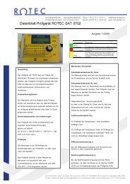
Measure unit <strong>UP</strong>-<strong>2210</strong><br />
The standard unit is fitted with one RS-485, two RS-<br />
232 communication ports and one USB port. Other<br />
options available include internal modem, external GSM<br />
modem, ISDN modem and Ethernet.<br />
The <strong>UP</strong>-<strong>2210</strong> can also be fitted with digital inputs and<br />
digital outputs. These may be assigned for other<br />
monitoring purposes such as circuit breaker tripping,<br />
security alarms in substations etc, or providing local<br />
alarm or control outputs.<br />
The <strong>UP</strong>-<strong>2210</strong> can also be equipped with a fault<br />
recorder module, which activates the unit's digital inputs<br />
for supervision of the status of circuit breakers, relays<br />
and other external equipment. Whenever there is a<br />
disturbance in the electrical grid the unit records voltage<br />
and current deviations, together with information about<br />
the connected external equipment.
Power Quality Monitor (<strong>UP</strong>-<strong>2210</strong>)<br />
The <strong>UP</strong>-<strong>2210</strong> is a full-featured, norm-compliant (IEC<br />
61000-4-30 Class A) power quality monitor capable of<br />
detecting any disturbances encountered in a network.<br />
It interfaces with the PQ Secure software package.<br />
Measure unit (<strong>UP</strong>-<strong>2210</strong>)<br />
The <strong>UP</strong>-<strong>2210</strong> is based on a powerful digital signal<br />
processor (DSP) which makes it possible to<br />
monitor all parameters simultaneously with high<br />
accuracy.<br />
The analogue sampling system is synchronised with the<br />
actual fundamental frequency, which ensures class A<br />
accuracy and precision as well as accurate event<br />
capturing.<br />
Each and every cycle is analysed in accordance with<br />
IEC 61000-4-7 (Harmonics), IEC 61000-4-15 (Flicker)<br />
and IEC 61000-4-30. The <strong>UP</strong>-<strong>2210</strong> can easily be set up<br />
to measure in accordance with EN 50160 or any other<br />
national or international standard, with<br />
automatic reporting to management or other any other<br />
interested receiver.<br />
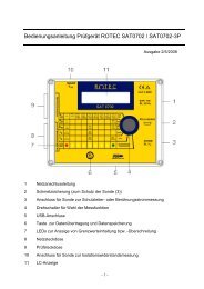
Graphical display<br />
An optional graphical display is also available. The unit<br />
is equipped with Unipower’s unique and user-friendly<br />
Turn&Click ® interface, and can be connected to a PC<br />
(RS-232) on-site via a front panel connector.<br />
Graphical Display Unit<br />
Analogue inputs<br />
The <strong>UP</strong>-<strong>2210</strong> has 4 differential voltage and 4<br />
differential voltage transient inputs. The bandwidth of<br />
each input is adapted to the appropriate application.<br />
When measuring harmonics a lower bandwidth is<br />
needed than when capturing transients.<br />
The <strong>UP</strong>-<strong>2210</strong> also has 4 differential current input<br />
channels. In low voltage networks the fourth current<br />
channel can be used to measure the neutral current.<br />
Ground fault application<br />
The fourth voltage channel can be used for earth point<br />
monitoring in order to find ground faults in impedance<br />
grounded networks.<br />
Earth leakage<br />
The <strong>UP</strong>-<strong>2210</strong> is automatically detecting any earth<br />
leakage by summing the phase (and neutral) currents. If<br />
there is a ground fault some current will flow in a<br />
different path and the leakage is detected.<br />
Digital Inputs and Fault Recording<br />
The <strong>UP</strong>-<strong>2210</strong> can be equipped with digital inputs that<br />
can interface with a variety of external equipment such<br />
as kWh-meters, water meters, protective relays, circuit<br />
breakers etc. By connecting signals from the protective<br />
relays, the <strong>UP</strong>-<strong>2210</strong> can work like a fault recorder,<br />
recording all signals upon a trig signal at a digital input.<br />
Digital Outputs<br />
The <strong>UP</strong>-<strong>2210</strong> can also be equipped with digital outputs<br />
that can be programmed to alarm when certain pre-set<br />
conditions are met. This in turn can alert other, external<br />
systems. The digital outputs can be used to synchronise<br />
other meters (or <strong>UP</strong>-<strong>2210</strong>) to record at en event.
Fault Recorder Module<br />
The <strong>UP</strong>-<strong>2210</strong> can also be equipped with a fault recorder<br />
module, which activates the unit's digital inputs<br />
for supervision of the status of circuit breakers, relays<br />
and other external equipment. Whenever there is a<br />
disturbance in the electrical grid the unit records voltage<br />
and current deviations, together with information about<br />
the connected external equipment.<br />
Fault Recorder window, displaying voltages, currents and<br />
digital input channels during a fault.<br />
GPS Module<br />
The <strong>UP</strong>-<strong>2210</strong> can also be equipped with a GPS<br />
module, for time-synchronisation of the <strong>UP</strong>-<strong>2210</strong> unit.<br />
Communication<br />
A central feature of <strong>UP</strong>-<strong>2210</strong> is the flexibility and ease<br />
of communication between the workstation and the<br />
permanently installed monitor. Communication can be<br />
via a wire, phone connection, radio (and GSM), fibre/<br />
wire, etc. The monitor has built-in RS-232, RS-485,<br />
USB, Ethernet and also a modem.<br />
Measured parameters<br />
The <strong>UP</strong>-<strong>2210</strong> has been developed as a full-featured<br />
power quality and transient monitor to simultaneously<br />
measure all events on all channels. Individual trigger<br />
levels can be set to enable an infinitely variable range of<br />
user-defined trigger conditions, either from the remote<br />
workstation or via a laptop directly connected to the<br />
monitor. If a disturbance occurs that exceeds the<br />
defined trigger levels the monitor will record the<br />
disturbance.<br />
The internal memory has been chosen so that there are<br />
no moving parts. Problems with hard disks are a thing<br />
of the past. Instead, the analyser stores the events on its<br />
solid-state internal memory using a sophisticated data<br />
compression technique so that 4 MB represents typically<br />
20 days storage. Remember that the key is the automatic<br />
download to the central database.<br />
Waveforms and power quality parameters can be viewed<br />
in real-time with PQ Online or as historical data with the PQ<br />
Secure software (SQL database).<br />
Basic parameters and demands<br />
All basic power quality parameters are measured<br />
continuously and can be viewed in real-time with<br />
PQ Online, or as historical data with PQ Secure.<br />
� Voltage (phase-phase, phase-neutral)<br />
� Current (phase-phase, phase-neutral)<br />
� Active, Reactive and Apparent Power<br />
� Active, Reactive and Apparent Energy<br />
� Power Factor and cos phi<br />
� Frequency
Harmonics<br />
Harmonic distortion is caused by non-linear generators<br />
or loads and can cause severe problems. For example,<br />
capacitor banks can easily be damaged and neutral<br />
connectors can overheat. To identify harmonic-related<br />
problems it is necessary to measure continuously. The<br />
<strong>UP</strong>-<strong>2210</strong> unit measures harmonics, both amplitude and<br />
phase, up to the 50th harmonic. Both THD-F, THD-R<br />
together with K-factor and harmonic power are<br />
calculated. All harmonics calculations are in accordance<br />
with IEC 61000-4-30 (IEC 61000-4-7). The <strong>UP</strong>-<strong>2210</strong><br />
also has a module for studying interharmonics and<br />
signalling.<br />
PQ Online: real-time evaluation of harmonics.<br />
Transients, Sags and Swells<br />
Disturbances in a power system are defined as voltage<br />
transients, sags or swells. Transients are fast disturbances<br />
originating from lightning, load switching etc. Voltage<br />
sags are short-duration low RMS-values generally<br />
caused by faults such as short circuits in the utility<br />
system. The reliability of a power system is critical to<br />
most businesses and is greatly affected by sags and<br />
swells.<br />
The <strong>UP</strong>-<strong>2210</strong> detects and categorises the type of<br />
disturbance, and helps to identify the source by<br />
determining the direction. It measures and calculates the<br />
RMS value for each half cycle and uses precision peak<br />
detectors to detect transients down to 1 microsecond<br />
duration. When a transient or a sag/swell occurs the<br />
<strong>UP</strong>-<strong>2210</strong> records it and stores all necessary data in the<br />
built-in memory. It is then automatically transferred to<br />
the workstation with a seamless timebase for evaluation.<br />
Transients and sags & swell measurements are based on<br />
IEC 61000-4-30.<br />
PQ Secure, Sag&Swell duration<br />
PQ Secure, Sag&Swell RMS evaluation window<br />
PQ Secure, Transient evaluation window
Flicker<br />
Fluctuating loads cause voltage variations that are often<br />
referred to as flicker. Lamps connected to such a<br />
voltage produce a flickering light, very annoying to the<br />
human eye. The <strong>UP</strong>-<strong>2210</strong> measures voltage flicker in<br />
accordance with IEC 61000-4-15 and calculates flicker<br />
parameters such as IFL, PST and PLT.<br />
PQ Secure, historical evaluation of PST,<br />
short-term flicker severity.<br />
Unbalance<br />
Unbalance is a condition where the three phases differ<br />
in amplitude. This unbalance is frequently expressed as<br />
the ratio of the negative phase sequence divided by the<br />
positive phase sequence, as a percentage. Even small<br />
amounts of voltage unbalance decrease the efficiency<br />
of a three-phase motor. Monitoring the unbalance can<br />
help to improve efficiency and increase the longevity of<br />
a motor.<br />
The <strong>UP</strong>-<strong>2210</strong> measures and stores the positive-, negative-<br />
and zero-phase sequence and the unbalance for<br />
both voltage and current in accordance with IEC<br />
61000-4-30.<br />
Real-time and troubleshooting<br />
Without interrupting the logging of all parameters, the<br />
<strong>UP</strong>-<strong>2210</strong> can show values in different real-time graphs.<br />
This makes a great tool that can be used when<br />
troubleshooting different problems on site as well as<br />
remote.<br />
Voltage, current, instantaneous flicker level and<br />
frequency in real-time.<br />
Mounting<br />
The <strong>UP</strong>-<strong>2210</strong> is a compact and rugged unit and is<br />
intended to be mounted permanently on site. The size is<br />
only 205 x 300 x 65 mm (width x height x depth) and<br />
ideal for mounting in any switchboard. An optional<br />
graphical display is also available for front panel<br />
monitoring on site and measures only 184 x 91 x 96<br />
mm. The display unit can be mounted remotely from<br />
the <strong>UP</strong>-<strong>2210</strong> and is equipped with an extra front panel<br />
RS-232 communication port to which a portable<br />
computer easily can be connected to view real-time<br />
parameters on site.<br />
<strong>UP</strong>-<strong>2210</strong> installed in a substation cabinet
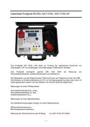
Example of wiring diagram, 3-phase, 3-wire delta<br />
with 3 PT´s and 3 CT´s<br />
Connections<br />
The <strong>UP</strong>-<strong>2210</strong> supports all power configurations as<br />
listed below.<br />
� 3-wire system<br />
� 4-wire system<br />
� Phase-to-phase, wye and delta configurations<br />
All calculations are based on the correct electrical<br />
configuration which is set from a drop-down menu.<br />
Typical Substation Application<br />
PT primary: 11 kV<br />
PT secondary: 110 V<br />
CT primary: 3000 A<br />
CT secondary: 5 A<br />
Digital In-/Outputs<br />
Communication<br />
(RS-485 in this case)<br />
PT´s<br />
UL3<br />
UL2<br />
UL1<br />
LINE<br />
L1 L2 L3<br />
CT<br />
CT<br />
LOAD<br />
CT<br />
Example of wiring diagram, 3-phase, 3-wire delta<br />
with 2 PT’s and 2 CT’s<br />
LOAD<br />
Installation<br />
� Fourth voltage input available for measurements in<br />
open delta configurations etc.<br />
� Fourth current input available for neutral or ground<br />
current measurements<br />
� 8 (32) digital inputs available for indication<br />
purposes such as circuit breaker tripping etc.<br />
� 2 digital outputs available for alarm purposes etc.<br />
Power supply<br />
(85-264 V AC /<br />
110-375 V DC)<br />
4 current inputs<br />
(0-6 A TRMS)<br />
4 voltage inputs<br />
(0-275 V TRMS)<br />
PT´s<br />
Connection box<br />
(connected to PT’s<br />
and CT’s)<br />
UL3-L2<br />
UL1-L2<br />
LINE<br />
L1 L2 L3<br />
CT<br />
CT
Technical Specification<br />
Voltage inputs<br />
Voltage channels 4 differential inputs<br />
Channel input level 0 - 275 V RMS<br />
Resolution 14 bit (84 dB)<br />
Basic sampling rate 256 samples/cycle<br />
Input impedance 2 Mohm<br />
Bandwidth 3.2 kHz analogue anti-aliasing filters<br />
Accuracy IEC 61000-4-30 class A (0.1%)<br />
For maximum accuracy, automatic synchronisation to the power frequency is performed by a<br />
phase-locked loop (PLL).<br />
Voltage transient inputs<br />
Voltage transient channels 8 differential inputs<br />
Channel input level +/- 1500 V peak level<br />
Resolution 14 bit (84 dB)<br />
Transient detection Fast transients (>1us / 1 MHz), sag/swells, interruptions<br />
Input impedance 2 Mohm<br />
Bandwidth 3 MHz<br />
Current inputs<br />
Current channels 4 differential inputs (fully isolated inputs optional)<br />
Channel input level 0 - 6 A RMS (voltage input optional)<br />
Resolution 14 bit<br />
Basic sampling rate 256 samples/cycle<br />
Input impedance max 10 mohm<br />
Bandwidth 3.2 kHz analogue anti-aliasing filters<br />
Accuracy 0.1%<br />
Digital inputs<br />
8 opto-isolated digital inputs (0-250 VDC). 16 or 32 channels optional.<br />
Digital outputs<br />
2 solid state relays (0-110 VDC, 0-110 mA). 4 channels optional.<br />
Time synchronisation<br />
Optional GPS unit for time synchronisation.<br />
Calculated parameters<br />
Power Quantities All 3-phase configurations. Active power [kW], Reactive power<br />
[kVAr], Apparent power [kVA], Power Factor and<br />
cosϕ (displacement factor), Active Energy [kWh], Reactive<br />
energy [kVArh], Apparent energy [kVAh]<br />
Energy accuracy class 0.2S (IEC 62053-22)<br />
Frequency 45 - 65 Hz<br />
Harmonics 0 - 50th individual harmonics of voltage and current in<br />
accordance with standard IEC 61000-4-30 Class A. THD<br />
factors (THD-R, THD-F, TDD, THD-I etc), K-factor<br />
Power Harmonics (PFFT)<br />
Flicker: IFL, Pst, Plt calculated in accordance with standard<br />
IEC 61000-4-30 Class A (IEC 61000-4-15)<br />
Voltage / Current Unbalance Positive-, negative- and zero phase sequence plus<br />
unbalance value (%) according to standard IEC 61000-4-30<br />
Signalling Voltage In accordance with EN 50160 and IEC 61000-4-30<br />
Memory capacity<br />
4 MB (8 MB is optional) built-in flash memory for measure data. A unit with standard memory<br />
will be able to measure for at least 20 days with normal configuration.<br />
Communication<br />
Built-in RS-232, RS-485 and USB. Optional Ethernet and internal modem. Support for external<br />
modems, radio devices, ISDN- and GSM/GPRS-modems.<br />
Standards<br />
Voltage Quality EN 50160, IEC 61000-2-2, IEC 61000-2-12 and other norms<br />
Harmonics Measurements IEC 61000-4-30 Class A (IEC 61000-4-7)<br />
Flicker Measurements IEC 61000-4-30 Class A (IEC 61000-4-15)<br />
Power Quality IEC 61000-4-30 Class A (Testing and measurement<br />
techniques)<br />
Mechanical data<br />
Size W x H x D 205 x 300 x 65 mm<br />
Operational temperature -10 ºC to +55 ºC<br />
Humidity 10% - 98% non-condensing<br />
Weight 1.3 kg<br />
Safety IEC 61 010-1<br />
EMC IEC 61000-6-4 and IEC 61000-6-2 (EN 50 081-1,2;<br />
EN 50 082-1,2)<br />
Calibration and self-test<br />
The calibration of <strong>UP</strong>-<strong>2210</strong> is software-based and is therefore easy to make directly on site<br />
without having to dismount the units. To assure maximum reliability the <strong>UP</strong>-<strong>2210</strong> always performs<br />
an automatic self-test (AST) before measuring.<br />
Power supply<br />
Standard: 110/230 V AC or 100-375 V DC<br />
Optional: 18-36 V DC or 36-72 V DC<br />
<strong>UP</strong>-<strong>2210</strong> main features:<br />
Sampling frequency<br />
High-speed sampling frequency (256 samples/cycle)<br />
gives a high accuracy of all measured parameters.<br />
Transient high speed capture<br />
High-speed transients down to 1 us are captured and<br />
the waveforms for all 8 channels are recorded and can<br />
easily be evaluated with pre- and post trig.<br />
Sag & Swell long time recording<br />
8-channel recording of sags/swells up to 10 seconds<br />
(every single cycle is recorded). Selectable pre- and posttrig.<br />
Realtime graphs<br />
Realtime values can be studied together with waveform,<br />
harmonics graph, vector diagram and unique realtime<br />
time graph of instantaneous flicker level and other<br />
parameters.<br />
Historical Trend graph<br />
Unique automatic historical trend graph that shows all<br />
important values 24 hours back in time in real-time<br />
mode. This can also be shown in the optional display<br />
unit that can be mounted in substations etc.<br />
PLL Sampling Synchronisation<br />
High accuracy of all measured parameters achieved by<br />
a synchronisation between the sampling of the input<br />
signals and the power frequency. The synchronisation is<br />
made possible by a built-in PLL (phase-locked loop).<br />
Flash memory<br />
Easy to upgrade with new software thanks to the<br />
built-in flash memory. No moving parts ensures total<br />
reliability.<br />
Unipower AB<br />
Box 411<br />
SE-441 28 ALINGSÅS<br />
Sweden<br />
www.unipower.se<br />
mail@unipower.se<br />
For more information, contact your local representative:<br />
Rev. 4.0 AE. Specifications are subject to change without notice.