Liebert CRV; Application Guide - Emerson Network Power
Liebert CRV; Application Guide - Emerson Network Power
Liebert CRV; Application Guide - Emerson Network Power

You also want an ePaper? Increase the reach of your titles
YUMPU automatically turns print PDFs into web optimized ePapers that Google loves.
<strong>Liebert</strong> ® <strong>CRV</strong> <br />
<strong>Application</strong> <strong>Guide</strong>–Air-Cooled, Water/Glycol-Cooled and Chilled Water, 50 & 60Hz<br />
Precision Cooling<br />
For Business-Critical Continuity
TABLE OF CONTENTS<br />
1.0 WHAT IS THE LIEBERT <strong>CRV</strong>? . . . . . . . . . . . . . . . . . . . . . . . . . . . . . . . . . . . . . . . . . . . . . . .1<br />
1.1 <strong>Liebert</strong> <strong>CRV</strong> Intended <strong>Application</strong> . . . . . . . . . . . . . . . . . . . . . . . . . . . . . . . . . . . . . . . . . . . . . . 1<br />
Figure 1 <strong>Liebert</strong> <strong>CRV</strong>—front and rear views . . . . . . . . . . . . . . . . . . . . . . . . . . . . . . . . . . . . . 1<br />
2.0 LIEBERT <strong>CRV</strong> CONTROLS. . . . . . . . . . . . . . . . . . . . . . . . . . . . . . . . . . . . . . . . . . . . . . . . . .2<br />
Table 1 Coupled and decoupled control schemes . . . . . . . . . . . . . . . . . . . . . . . . . . . . . . . . . 2<br />
2.1 <strong>Liebert</strong> <strong>CRV</strong> Sensor Location <strong>Guide</strong>lines . . . . . . . . . . . . . . . . . . . . . . . . . . . . . . . . . . . . . . . . . 2<br />
3.0 GENERAL LIEBERT <strong>CRV</strong> GUIDELINES . . . . . . . . . . . . . . . . . . . . . . . . . . . . . . . . . . . . . . . . .3<br />
4.0 SITE APPLICATION AND UNIT PLACEMENT. . . . . . . . . . . . . . . . . . . . . . . . . . . . . . . . . . . . . .4<br />
Scenario 1: Single Equipment Row . . . . . . . . . . . . . . . . . . . . . . . . . . . . . . . . . . . . . . . . . . . . . . 4<br />
Scenario 2: Double Equipment Row . . . . . . . . . . . . . . . . . . . . . . . . . . . . . . . . . . . . . . . . . . . . . 4<br />
Scenario 3: Redundancy . . . . . . . . . . . . . . . . . . . . . . . . . . . . . . . . . . . . . . . . . . . . . . . . . . . . . . . 5<br />
Scenario 4: Partial Containment . . . . . . . . . . . . . . . . . . . . . . . . . . . . . . . . . . . . . . . . . . . . . . . . 6<br />
Scenario 5: Cold-Aisle Containment . . . . . . . . . . . . . . . . . . . . . . . . . . . . . . . . . . . . . . . . . . . . . 6<br />
i
1.0 WHAT IS THE LIEBERT <strong>CRV</strong>?<br />
1<br />
What is the <strong>Liebert</strong> <strong>CRV</strong>?<br />
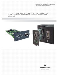
The <strong>Liebert</strong> <strong>CRV</strong> is a Precision Cooling unit intended to be located within a row of heat-generating IT<br />
equipment racks. The <strong>Liebert</strong> <strong>CRV</strong> provides all the necessary functions of a precision air conditioner<br />
including cooling, humidification, dehumidification, air filtration and condensate management. Air<br />
enters the <strong>Liebert</strong> <strong>CRV</strong> unit from the hot aisle. The air, filtered, cooled and conditioned, is discharged<br />
into the cold aisle through an adjustable supply air baffle. The supply air baffle allows the air leaving<br />
the cooling unit to be directed to the racks the <strong>Liebert</strong> <strong>CRV</strong> is conditioning; maximizing its effectiveness,<br />
reducing the chance for hot spots and improving the overall system efficiency.<br />
The <strong>Liebert</strong> <strong>CRV</strong> is optimized for maximum cooling capacity in a minimal footprint. The extremely<br />
energy efficient components of the system are managed by the <strong>Liebert</strong> iCOM control system. The<br />
environment is monitored in real time by the <strong>Liebert</strong> iCOM control through sensors positioned in a<br />
variety of locations. Sensors located in the return air, supply air and rack inlets allow the unit to optimize<br />
its operations for both performance and energy efficiency. All unit operations and sensor data<br />
can be reported remotely via a variety of communication protocols, providing end users with a built-in<br />
mini-monitoring system.<br />
1.1 <strong>Liebert</strong> <strong>CRV</strong> Intended <strong>Application</strong><br />
The <strong>Liebert</strong> <strong>CRV</strong> can be utilized in a variety of applications. Since the <strong>Liebert</strong> <strong>CRV</strong> provides complete<br />
temperature and humidity control along with filtration, it can be deployed as the only cooling unit in<br />
small data centers and network closets. Larger data centers are able to benefit from its standard<br />
rack-sized footprint, deploying it as a supplemental spot cooler to address both hot spots and high-density<br />
racks. The small footprint and variable cooling and airflow allow the <strong>Liebert</strong> <strong>CRV</strong> to be initially<br />
oversized in anticipation of future IT expansion without any footprint or energy consumption penalties.<br />
The <strong>Liebert</strong> <strong>CRV</strong> can be applied on both raised and non-raised floors, allowing it work with existing<br />
under floor and overhead cooling systems. The <strong>Liebert</strong> <strong>CRV</strong> can operate in conjunction with an<br />
existing <strong>Liebert</strong> XD installation, or provide an excellent alternative for sites that are unable to support<br />
a <strong>Liebert</strong> XD system. The <strong>Liebert</strong> <strong>CRV</strong> is compatible with all types of aisle containment designs;<br />
however the <strong>Liebert</strong> <strong>CRV</strong> control algorithms have been optimized for cold-aisle containment.<br />
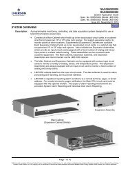
Figure 1 <strong>Liebert</strong> <strong>CRV</strong>—front and rear views<br />
Front Rear
2.0 LIEBERT <strong>CRV</strong> CONTROLS<br />
2<br />
<strong>Liebert</strong> <strong>CRV</strong> Controls<br />
The <strong>Liebert</strong> <strong>CRV</strong> is equipped with the latest in <strong>Liebert</strong> iCOM controls. Available in every <strong>Liebert</strong><br />
<strong>CRV</strong> is a return temperature and humidity sensor, a supply temperature sensor and three remote<br />
rack sensors with the option to add an additional seven remote rack sensors. Each rack sensor takes<br />
two temperature readings and can be configured to report either the average or the higher of the two<br />
sensors.<br />
The <strong>Liebert</strong> iCOM controller on the <strong>Liebert</strong> <strong>CRV</strong> leaves the factory with the fan speed and cooling<br />
capacity controlled by the supply air sensor. This control mode is extremely robust and will ensure<br />
delivery of precise cooling to the cold aisle. To unlock the full capability of the <strong>Liebert</strong> <strong>CRV</strong>, remote<br />
rack sensors can be installed, which will allow the fan speed and the cooling capacity to be “decoupled.”<br />
Decoupling means that the fan speed can now be controlled from the remote rack sensors and<br />
the cooling capacity controlled from the supply air sensor. In this advanced configuration, the <strong>Liebert</strong><br />
<strong>CRV</strong> can now control the discharge temperature of the unit by modulating cooling capacity based on<br />
the supply sensor and use the remote rack sensors to ensure that the cool air is being delivered to the<br />
inlet of the racks. Using the supply and remote rack sensors in this decoupled mode is the preferred<br />
method for controlling the <strong>Liebert</strong> <strong>CRV</strong> in a hot-aisle/cold-aisle configuration. In addition to this configuration<br />
the <strong>Liebert</strong> <strong>CRV</strong> has additional flexibility for other applications that can be understood in<br />
Table 1.<br />
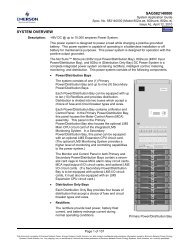
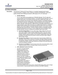
Table 1 Coupled and decoupled control schemes<br />
Fan<br />
Speed<br />
Supply Air Sensor<br />
Remote Air Sensor<br />
Return Air Sensor<br />
Supply<br />
Air Sensor<br />
A<br />
(Coupled)<br />
D<br />
(Decoupled)<br />
E<br />
(Decoupled)<br />
Cooling Capacity<br />
Remote<br />
Air Sensor<br />
Table 1 shows the flexibility of the <strong>Liebert</strong> <strong>CRV</strong> and how different sensor locations can be used to<br />
control the <strong>Liebert</strong> <strong>CRV</strong> fan speed and cooling capacity. The configurations labeled “A,” “B” and “C”<br />
are defined as coupled control schemes. These coupled control schemes allow both the cooling and fan<br />
speed to be controlled by the same sensor input, either from the supply air sensor, remote air sensor<br />
or return air sensor. Schemes labeled “D,” “E” and “F” are defined as decoupled control schemes.<br />
These decoupled control schemes use separate sensor inputs for controlling the fan speed and cooling.<br />
For instance, an alternate to the factory default control program is “D,” where the fans are controlled<br />
by the remote rack-mounted temperature sensors and the cooling is controlled by the discharge air<br />
temperature sensor in the <strong>Liebert</strong> <strong>CRV</strong>.<br />
2.1 <strong>Liebert</strong> <strong>CRV</strong> Sensor Location <strong>Guide</strong>lines<br />
Return<br />
Air Sensor<br />
— —<br />
B<br />
(Coupled)<br />
F<br />
(Decoupled)<br />
Three rack sensors come with the <strong>Liebert</strong> <strong>CRV</strong> unit to help prevent any problem spots in the row.<br />
Rack sensors help combat cooling problems related to recirculation of air, uneven rack loading and air<br />
distribution. The rack sensors are intended for use in the cold aisle only. To ensure effective cooling<br />
provided by a <strong>Liebert</strong> <strong>CRV</strong>, follow these suggestions for locating the rack sensor probes:<br />
• Place on the top of the perforated rack door.<br />
• In front of the highest-mounted servers in the rack.<br />
• In front of the highest-density area of the rack.<br />
• In the airflow path entering the rack.<br />
• Do not place the probe directly on the metal surface of the perforated door.<br />
Additional information about sensor location can be found in the <strong>Liebert</strong> <strong>CRV</strong> Installation, Operation<br />
and Maintenance manual, SL-11975, which is available at <strong>Liebert</strong>’s Web site: www.liebert.com<br />
—<br />
C<br />
(Coupled)
3.0 GENERAL LIEBERT <strong>CRV</strong> GUIDELINES<br />
3<br />
General <strong>Liebert</strong> <strong>CRV</strong> <strong>Guide</strong>lines<br />
The <strong>Liebert</strong> <strong>CRV</strong> is capable of supporting many varied room configurations. Following a few basic<br />
guidelines, the <strong>Liebert</strong> <strong>CRV</strong> can provide efficient and precision cooling to the space and adjacent rack<br />
mounted equipment. The following points are highly effective recommendations for precision performance<br />
and efficient operation of the <strong>Liebert</strong> <strong>CRV</strong> in many room layouts:<br />
• Distribute equipment as evenly as possible across the height of the rack.<br />
• Use blanking panels to prevent recirculation of air through gaps in rack equipment.<br />
• Locate racks closely together, preventing gaps between equipment racks.<br />
• Where applicable, use dividers to prevent hot air wrap around to the cold aisle.<br />
• Locate the <strong>Liebert</strong> <strong>CRV</strong> appropriately to effectively deliver cooling to the rack row.<br />
The application of a <strong>Liebert</strong> <strong>CRV</strong> is meant to provide cooling to between two and six racks of equipment<br />
in a single row. A row of equipment longer than six racks might not receive the appropriate<br />
quantity of conditioned air from a single <strong>Liebert</strong> <strong>CRV</strong> unit. The total number of racks that can be<br />
cooled will depend fully upon the rack loads and airflow requirements of the equipment to be cooled,<br />
as well as the type and size of the <strong>Liebert</strong> <strong>CRV</strong> selected. In conjunction with <strong>Liebert</strong> <strong>CRV</strong> placement,<br />
maintaining a cold aisle between three and four feet wide is highly suggested. This is beneficial<br />
because it provides a smaller volume for conditioned air to inhabit, preventing hot aisle air intrusion.<br />
The density of the conditioned air will help to prevent hot aisle air from recirculating through the<br />
rack equipment. Wider cold aisles can be utilized with cold aisle containment designs, including the<br />
<strong>Liebert</strong> Cold Aisle Containment product line.
4.0 SITE APPLICATION AND UNIT PLACEMENT<br />
Scenario 1: Single Equipment Row<br />
4<br />
Site <strong>Application</strong> and Unit Placement<br />
The <strong>Liebert</strong> <strong>CRV</strong> is intended to cool a single row of racks by providing a curtain of cold discharge air<br />
across the face of the equipment. Ideally the <strong>Liebert</strong> <strong>CRV</strong> should be located at the end of the rack row<br />
with a three to four foot cold aisle. Adjustment to the baffle system will allow cooling to be directed<br />
down the row effectively delivering coverage to the rack row.<br />
NOTE<br />
It is not ideal to place the <strong>Liebert</strong> <strong>CRV</strong> in the middle of a single rack row. Middle placement<br />
may create hot spots at the top of the rack equipment, due to inconsistent air coverage.<br />
Scenario 2: Double Equipment Row<br />
When using a <strong>Liebert</strong> <strong>CRV</strong> with double rack rows, location of the <strong>Liebert</strong> <strong>CRV</strong> unit is similar to the<br />
single-row placement. Locate the <strong>Liebert</strong> <strong>CRV</strong>s at opposite ends of the two rows and adjust the air<br />
baffles in the direction of desired cooling. Placing the <strong>Liebert</strong> <strong>CRV</strong> at opposite ends of each row will<br />
allow the <strong>Liebert</strong> <strong>CRV</strong>s to provide coverage for both rack rows by pressurizing the cold aisle.<br />
Increased pressurization in the cold aisle helps to eliminate any hot spots from developing in the row.<br />
Double-row usage simulates a containment approach. The opposing rack row acts as a wall or partition,<br />
helping to contain the provided cooling in the cold aisle instead of allowing it to spread throughout<br />
the space that the equipment is located.<br />
NOTE<br />
It is not suggested to locate two <strong>Liebert</strong> <strong>CRV</strong> units directly across from one another or by<br />
locating two units adjacent to one another in a row. Both situations have potential to reduce<br />
the effective cooling of both <strong>Liebert</strong> <strong>CRV</strong> units in the row. If more than one <strong>Liebert</strong> <strong>CRV</strong> unit<br />
needs to be placed within a row, separation of at least one rack is recommended.
Scenario 3: Redundancy<br />
Single-Row Redundancy<br />
5<br />
Site <strong>Application</strong> and Unit Placement<br />
Single-row redundancy can be achieved by locating two <strong>Liebert</strong> <strong>CRV</strong> units at opposite ends of a row,<br />
as shown. Directing the air baffles toward one another and down the face of the rack row will allow<br />
the <strong>Liebert</strong> <strong>CRV</strong> units to operate at partial load while providing the required cooling. If a unit failure<br />
should occur, the remaining unit will ramp up airflow, respond to the higher return air temperature<br />
and provide the required cooling based on input from sensor data. This scenario can also work in a<br />
lead/lag operation or duty cycle scenario, by running a single <strong>Liebert</strong> <strong>CRV</strong> to match the load with the<br />
secondary unit in standby. Two or more <strong>Liebert</strong> <strong>CRV</strong>s can be networked together for teamwork,<br />
lead/lag or cascade operation.<br />
Dual-Row Redundancy<br />
Dual-row redundancy can be achieved in a similar manner to a single row redundancy plan. In this<br />
scenario, two single rows are facing one another, sharing a cold aisle. <strong>Liebert</strong> <strong>CRV</strong> units may be networked<br />
together to provide shared informed coverage of the row equipment demands. Redundancy<br />
can be accomplished by locating <strong>Liebert</strong> <strong>CRV</strong>s at the ends of the rows and directing their airflow<br />
inward towards the equipment row, as shown. Operating all four <strong>Liebert</strong> <strong>CRV</strong> units at partial load or<br />
two units at full load with two in standby is recommended for unit redundancy. Furthermore, it is<br />
suggested that when utilizing this configuration, <strong>Liebert</strong> <strong>CRV</strong>s at opposite ends of the rows should be<br />
in operation, to deliver the most effective coverage to the equipment. Aligning two <strong>Liebert</strong> <strong>CRV</strong>s<br />
across the row from one another is an acceptable design, assuming that each <strong>Liebert</strong> <strong>CRV</strong> will be<br />
operating at partial capacity or operating together at full capacity only in an emergency situation.<br />
NOTE<br />
Equipment loads that require a greater amount of cooling can utilize additional <strong>Liebert</strong> <strong>CRV</strong>s<br />
located in-between the row of equipment. The discharge of the in-between <strong>Liebert</strong> <strong>CRV</strong>s should<br />
be directed both to the left and right, adding supplemental cooling to the effect of the <strong>Liebert</strong><br />
<strong>CRV</strong>s located at the end of the row.
Scenario 4: Partial Containment<br />
6<br />
Site <strong>Application</strong> and Unit Placement<br />
The <strong>Liebert</strong> <strong>CRV</strong> is most effective when the cold aisle can be contained by a natural or manufactured<br />
obstruction opposite to the face of the unit. As can be seen in this layout, a single <strong>Liebert</strong> <strong>CRV</strong> is positioned<br />
at the end of a rack row that is parallel to a room wall. The wall opposing the row equipment<br />
acts as a containment barrier supporting pressurization of the cold aisle. Additionally, the end of the<br />
equipment row being located on a room wall acts as an end panel preventing wraparound of cool mixing<br />
with the hot aisle air. In conjunction with this effect, the <strong>Liebert</strong> <strong>CRV</strong> discharge is positioned to<br />
provide a curtain of cooling that encapsulates the cold aisle, acting as an end cap to the cold aisle.<br />
NOTE<br />
To achieve a level of redundancy in this scenario, it is suggested to locate an additional <strong>Liebert</strong><br />
<strong>CRV</strong> in one of two locations. Locate an additional operating <strong>Liebert</strong> <strong>CRV</strong> at the end of the<br />
equipment row adjacent to the wall (to the far left in the illustration above). The two units will<br />
operate at a reduced capacity each, while still providing the required cooling. Should a failure<br />
of a unit occur, the remaining <strong>Liebert</strong> <strong>CRV</strong> unit will be able to provide cooling and airflow<br />
requirements from an acceptable position. Alternatively, locate a standby, non-operating<br />
<strong>Liebert</strong> <strong>CRV</strong> adjacent to the operating <strong>Liebert</strong> <strong>CRV</strong>. This allows for the same basic positioning<br />
of the unit while maintaining the intent of this scenario.<br />
Scenario 5: Cold-Aisle Containment<br />
The <strong>Liebert</strong> <strong>CRV</strong> is ideal for use with a cold-aisle containment approach, with the <strong>Liebert</strong> Cold Aisle<br />
Containment solution or similar products. Utilizing the <strong>Liebert</strong> <strong>CRV</strong> in conjunction with cold-aisle<br />
containment products does not limit the location of the <strong>Liebert</strong> <strong>CRV</strong> with respect to the rack row. The<br />
<strong>Liebert</strong> <strong>CRV</strong> can be located anywhere within the equipment row, with the unit’s discharge air baffle<br />
directed as the equipment airflow needs demand. The cold aisle containment completely encapsulates<br />
the available cooling in the aisle maximizing cooling efficiency while preventing hot air intrusion<br />
through, around or over the row of equipment.
Ensuring The High Availability<br />
Of Mission-Critical Data And <strong>Application</strong>s.<br />
<strong>Emerson</strong> <strong>Network</strong> <strong>Power</strong>, the global leader in enabling business-critical<br />
continuity, ensures network resiliency and adaptability through<br />
a family of technologies—including <strong>Liebert</strong> power and cooling<br />
technologies—that protect and support business-critical systems.<br />
<strong>Liebert</strong> solutions employ an adaptive architecture that responds<br />
to changes in criticality, density and capacity. Enterprises benefit<br />
from greater IT system availability, operational flexibility and<br />
reduced capital equipment and operating costs.<br />
While every precaution has been taken to ensure the accuracy<br />
and completeness of this literature, <strong>Liebert</strong> Corporation assumes no<br />
responsibility and disclaims all liability for damages resulting from use of<br />
this information or for any errors or omissions.<br />
© 2009 <strong>Liebert</strong> Corporation<br />
All rights reserved throughout the world. Specifications subject to change<br />
without notice.<br />
® <strong>Liebert</strong> is a registered trademark of <strong>Liebert</strong> Corporation.<br />
All names referred to are trademarks<br />
or registered trademarks of their respective owners.<br />
SL-11979_REV1_06-10<br />
<strong>Emerson</strong> <strong>Network</strong> <strong>Power</strong>.<br />
The global leader in enabling Business-Critical Continuity <br />
AC <strong>Power</strong><br />
Connectivity<br />
DC <strong>Power</strong><br />
Embedded Computing<br />
Embedded <strong>Power</strong><br />
Infrastructure Management & Monitoring<br />
Outside Plant<br />
<strong>Power</strong> Switching & Controls<br />
Precision Cooling<br />
Technical Support / Service<br />
Web Site<br />
www.liebert.com<br />
Monitoring<br />
liebert.monitoring@emerson.com<br />
800-222-5877<br />
Outside North America: +00800 1155 4499<br />
Single-Phase UPS & Server Cabinets<br />
liebert.upstech@emerson.com<br />
800-222-5877<br />
Outside North America: +00800 1155 4499<br />
Three-Phase UPS & <strong>Power</strong> Systems<br />
800-543-2378<br />
Outside North America: 614-841-6598<br />
Environmental Systems<br />
800-543-2778<br />
Outside the United States: 614-888-0246<br />
Locations<br />
United States<br />
1050 Dearborn Drive<br />
P.O. Box 29186<br />
Columbus, OH 43229<br />
Europe<br />
Via Leonardo Da Vinci 8<br />
Zona Industriale Tognana<br />
35028 Piove Di Sacco (PD) Italy<br />
+39 049 9719 111<br />
Fax: +39 049 5841 257<br />
Asia<br />
29/F, The Orient Square Building<br />
F. Ortigas Jr. Road, Ortigas Center<br />
Pasig City 1605<br />
Philippines<br />
+63 2 687 6615<br />
Fax: +63 2 730 9572<br />
<strong>Emerson</strong><strong>Network</strong><strong>Power</strong>.com<br />
Racks & Integrated Cabinets<br />
Services<br />
Surge Protection<br />
<strong>Emerson</strong>, Business-Critical Continuity, <strong>Emerson</strong> <strong>Network</strong> <strong>Power</strong> and the <strong>Emerson</strong> <strong>Network</strong> <strong>Power</strong> logo are trademarks of <strong>Emerson</strong> Electric Co. or one of its affiliated companies.<br />
©2009 <strong>Emerson</strong> Electric Co.