Filament temperature of low power incandesecent lamps: Stefan ...
Filament temperature of low power incandesecent lamps: Stefan ...
Filament temperature of low power incandesecent lamps: Stefan ...

You also want an ePaper? Increase the reach of your titles
YUMPU automatically turns print PDFs into web optimized ePapers that Google loves.
<strong>Filament</strong> <strong>temperature</strong> <strong>of</strong> <strong>low</strong> <strong>power</strong> <strong>incandesecent</strong> <strong>lamps</strong>: <strong>Stefan</strong>-Boltzmann law<br />
[2]. Therefore, in this work e = 0.35 was used. However,<br />
the measured <strong>temperature</strong> values were larger (by less than<br />
2.5%) for e = 0.3 and smaller (by less than 1.5%) for e =<br />
0.4 when both compared with those obtained for e = 0.35.<br />
III. MODELING<br />
At a given voltage across the filament <strong>of</strong> the lamp, a steady<br />
state is reached when the current (I) passing through the<br />
filament is stabilized. In the steady state it is expected that<br />
the electrical <strong>power</strong> input to the lamp is equal to the <strong>power</strong><br />
lost by the filament through conductive, convective, and<br />
radiative processes, such that [2]<br />
V 2 / R = K (T – T0) + e σ As (T 4 – T0 4 ), (1)<br />
where K represents conductive and convective properties<br />
<strong>of</strong> the system. T and T0 are the <strong>temperature</strong>s in Kelvin for<br />
the filament and the ambient, respectively. e and As are the<br />
emissivity and surface area <strong>of</strong> the filament, respectively,<br />
and σ is the <strong>Stefan</strong>-Boltzmann constant.<br />
For higher <strong>temperature</strong> <strong>of</strong> the filament (say above 1000<br />
K), it is reasonable to assume that T 4 >> T0 4 . Moreover,<br />
for <strong>low</strong> <strong>power</strong> bulbs [2], such as those used in the present<br />
work, the literature indicates that convection and<br />
conduction losses are negligible. Hence Eq. (1) may be<br />
rewritten as<br />
V 2 = e σ As T 4 R . (2)<br />
Metal resistance increases with <strong>temperature</strong>. The<br />
<strong>temperature</strong> <strong>of</strong> tungsten in the range 300 K to 3655 K, can<br />
be given in terms <strong>of</strong> its resistivity (ρ) by the empirical<br />
relation, valid in SI units [7]<br />
T = 3.05 × 10 8 ρ 0.83 and<br />
p = 0.46. (6b)<br />
The resistance <strong>of</strong> the filament at room <strong>temperature</strong> (RRT) is<br />
given by<br />
RRT = ρRT (L / πr<br />
. (3)<br />
A <strong>power</strong> relation similar to this is also given in Ref. [3, 8].<br />
Eq. (3) may be written as<br />
2 ), (6c)<br />
where ρRT is the resistivity <strong>of</strong> tungsten at room<br />
<strong>temperature</strong>, given by Eq.(3).<br />
Similarly by eliminating R from Eq. (2) and (5), we<br />
obtain an expression relating T with V, such as<br />
T = B2 V q , (7)<br />
where<br />
B2 = 2.4 ×10 3 r 0.19 L –0.38 and<br />
, (7a)<br />
q = 0.38. (7b)<br />
In the present work we have measured R and T both as<br />
functions <strong>of</strong> V.<br />
IV. RESULTS AND DISCUSSION<br />
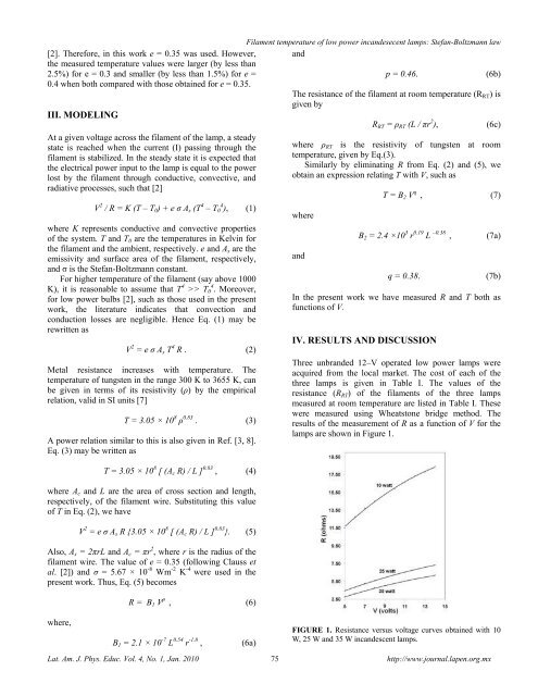
Three unbranded 12–V operated <strong>low</strong> <strong>power</strong> <strong>lamps</strong> were<br />
acquired from the local market. The cost <strong>of</strong> each <strong>of</strong> the<br />
three <strong>lamps</strong> is given in Table I. The values <strong>of</strong> the<br />
resistance (RRT) <strong>of</strong> the filaments <strong>of</strong> the three <strong>lamps</strong><br />
measured at room <strong>temperature</strong> are listed in Table I. These<br />
were measured using Wheatstone bridge method. The<br />
results <strong>of</strong> the measurement <strong>of</strong> R as a function <strong>of</strong> V for the<br />
<strong>lamps</strong> are shown in Figure 1.<br />
T = 3.05 × 10 8 [ (Ac R) / L ] 0.83 , (4)<br />
where Ac and L are the area <strong>of</strong> cross section and length,<br />
respectively, <strong>of</strong> the filament wire. Substituting this value<br />
<strong>of</strong> T in Eq. (2), we have<br />
V 2 = e σ As R {3.05 × 10 8 [ (Ac R) / L ] 0.83 }. (5)<br />
Also, As = 2πrL and Ac = πr 2 , where r is the radius <strong>of</strong> the<br />
filament wire. The value <strong>of</strong> e = 0.35 (fol<strong>low</strong>ing Clauss et<br />
al. [2]) and σ = 5.67 × 10 -8 Wm -2 K -4 were used in the<br />
present work. Thus, Eq. (5) becomes<br />
where,<br />
R = B1 V p , (6)<br />
B1 = 2.1 × 10 -7 L 0.54 r -1.8 , (6a)<br />
FIGURE 1. Resistance versus voltage curves obtained with 10<br />
W, 25 W and 35 W incandescent <strong>lamps</strong>.<br />
Lat. Am. J. Phys. Educ. Vol. 4, No. 1, Jan. 2010 75 http://www.journal.lapen.org.mx
![Diversas formas de visualizar estados en un sistema cuántico [PDF]](https://img.yumpu.com/51151303/1/190x245/diversas-formas-de-visualizar-estados-en-un-sistema-cuantico-pdf.jpg?quality=85)
![Precession and nutation visualized [PDF]](https://img.yumpu.com/50786044/1/190x245/precession-and-nutation-visualized-pdf.jpg?quality=85)
![Index [PDF] - Latin-American Journal of Physics Education](https://img.yumpu.com/47984121/1/190x245/index-pdf-latin-american-journal-of-physics-education.jpg?quality=85)
![Flujo de agua en botellas como experimento didáctico [PDF]](https://img.yumpu.com/43536300/1/190x245/flujo-de-agua-en-botellas-como-experimento-didactico-pdf.jpg?quality=85)