ONE-LOK™ Series D-SLCE for PVC Pipe - SIGMA Corporation
ONE-LOK™ Series D-SLCE for PVC Pipe - SIGMA Corporation
ONE-LOK™ Series D-SLCE for PVC Pipe - SIGMA Corporation

Create successful ePaper yourself
Turn your PDF publications into a flip-book with our unique Google optimized e-Paper software.
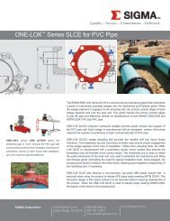
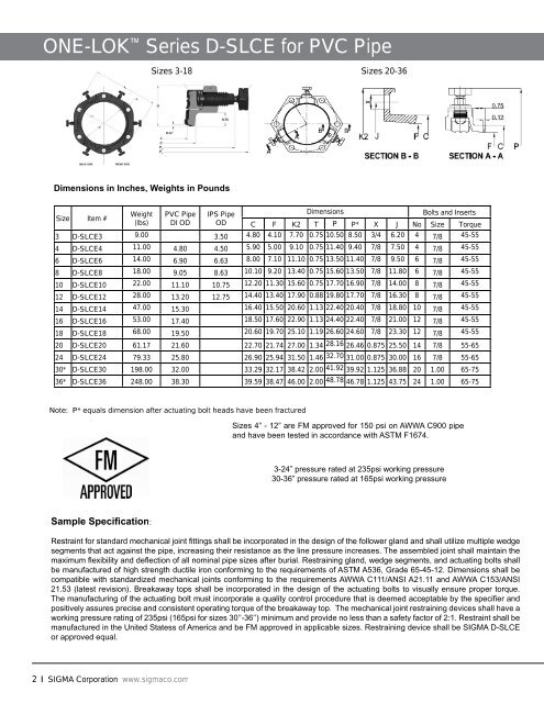
<strong>ONE</strong>-LOK <strong>Series</strong> D-<strong>SLCE</strong> <strong>for</strong> <strong>PVC</strong> <strong>Pipe</strong><br />
Dimensions in Inches, Weights in Pounds<br />
Size Item #<br />
Weight<br />
(lbs)<br />
<strong>PVC</strong> <strong>Pipe</strong><br />
DI OD<br />
2 <strong>SIGMA</strong> <strong>Corporation</strong> www.sigmaco.com<br />
IPS <strong>Pipe</strong><br />
OD<br />
Dimensions Bolts and Inserts<br />
C F K2 T P P* X J No Size Torque<br />
3 D-<strong>SLCE</strong>3 9.00 3.50 4.80 4.10 7.70 0.75 10.50 8.50 3/4 6.20 4 7/8 45-55<br />
4 D-<strong>SLCE</strong>4 11.00 4.80 4.50 5.90 5.00 9.10 0.75 11.40 9.40 7/8 7.50 4 7/8 45-55<br />
6 D-<strong>SLCE</strong>6 14.00 6.90 6.63 8.00 7.10 11.10 0.75 13.50 11.40 7/8 9.50 6 7/8 45-55<br />
8 D-<strong>SLCE</strong>8 18.00 9.05 8.63 10.10 9.20 13.40 0.75 15.60 13.50 7/8 11.80 6 7/8 45-55<br />
10 D-<strong>SLCE</strong>10 22.00 11.10 10.75 12.20 11.30 15.60 0.75 17.70 16.90 7/8 14.00 8 7/8 45-55<br />
12 D-<strong>SLCE</strong>12 28.00 13.20 12.75 14.40 13.40 17.90 0.88 19.80 17.70 7/8 16.30 8 7/8 45-55<br />
14 D-<strong>SLCE</strong>14 47.00 15.30 16.40 15.50 20.60 1.13 22.40 20.40 7/8 18.80 10 7/8 45-55<br />
16 D-<strong>SLCE</strong>16 53.00 17.40 18.50 17.60 22.90 1.13 24.40 22.40 7/8 21.00 12 7/8 45-55<br />
18 D-<strong>SLCE</strong>18 68.00 19.50 20.60 19.70 25.10 1.19 26.60 24.60 7/8 23.30 12 7/8 45-55<br />
20 D-<strong>SLCE</strong>20 61.17 21.60 22.70 21.74 27.00 1.34 28.16 26.46 0.875 25.50 14 7/8 55-65<br />
24 D-<strong>SLCE</strong>24 79.33 25.80 26.90 25.94 31.50 1.46 32.70 31.00 0.875 30.00 16 7/8 55-65<br />
30* D-<strong>SLCE</strong>30 198.00 32.00 33.29 32.17 38.42 2.00 41.92 39.92 1.125 36.88 20 1.00 65-75<br />
36* D-<strong>SLCE</strong>36 248.00 38.30 39.59 38.47 46.00 2.00 48.78 46.78 1.125 43.75 24 1.00 65-75<br />
Sample Specifi cation:<br />
Sizes 3-18 Sizes 20-36<br />
Note: P* equals dimension after actuating bolt heads have been fractured<br />
Sizes 4” - 12” are FM approved <strong>for</strong> 150 psi on AWWA C900 pipe<br />
and have been tested in accordance with ASTM F1674.<br />
3-24” pressure rated at 235psi working pressure<br />
30-36” pressure rated at 165psi working pressure<br />
Restraint <strong>for</strong> standard mechanical joint fi ttings shall be incorporated in the design of the follower gland and shall utilize multiple wedge<br />
segments that act against the pipe, increasing their resistance as the line pressure increases. The assembled joint shall maintain the<br />
maximum fl exibility and defl ection of all nominal pipe sizes after burial. Restraining gland, wedge segments, and actuating bolts shall<br />
be manufactured of high strength ductile iron con<strong>for</strong>ming to the requirements of ASTM A536, Grade 65-45-12. Dimensions shall be<br />
compatible with standardized mechanical joints con<strong>for</strong>ming to the requirements AWWA C111/ANSI A21.11 and AWWA C153/ANSI<br />
21.53 (latest revision). Breakaway tops shall be incorporated in the design of the actuating bolts to visually ensure proper torque.<br />
The manufacturing of the actuating bolt must incorporate a quality control procedure that is deemed acceptable by the specifi er and<br />
positively assures precise and consistent operating torque of the breakaway top. The mechanical joint restraining devices shall have a<br />
working pressure rating of 235psi (165psi <strong>for</strong> sizes 30’’-36’’) minimum and provide no less than a safety factor of 2:1. Restraint shall be<br />
manufactured in the United Statess of America and be FM approved in applicable sizes. Restraining device shall be <strong>SIGMA</strong> D-<strong>SLCE</strong><br />
or approved equal.