NMRA-DCC/Motorola Locomotive Decoder with Load Control - Kuehn
NMRA-DCC/Motorola Locomotive Decoder with Load Control - Kuehn
NMRA-DCC/Motorola Locomotive Decoder with Load Control - Kuehn

Create successful ePaper yourself
Turn your PDF publications into a flip-book with our unique Google optimized e-Paper software.
4 Instruction manual T125/T145<br />
4) To connect DC motors solder the orange wire to the motor terminal, which was<br />
connected to the right wheel pick-up before installation. Solder the grey wire to the<br />
motor terminal, which was connected to the left wheel pick-up. The RFI<br />
suppression components, which were connected to the motor before<br />
installation, should remain in the circuit in front of the motor. Otherwise<br />
disturbances, generated by the motor, could impair the functionality of the decoder.<br />
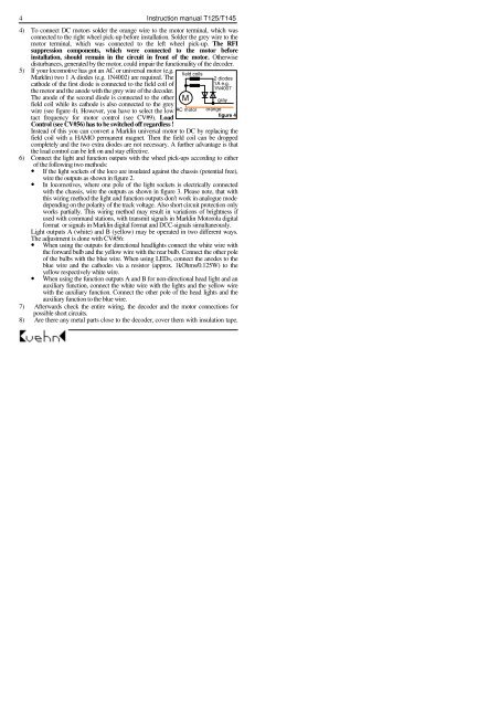
5) If your locomotive has got an AC or universal motor (e.g.<br />
Marklin) two 1 A diodes (e.g. 1N4002) are required. The<br />
cathode of the first diode is connected to the field coil of<br />
the motor and the anode <strong>with</strong> the grey wire of the decoder.<br />
The anode of the second diode is connected to the other<br />
field coil while its cathode is also connected to the grey<br />
field coils<br />
2 diodes<br />
1A e.g.<br />
1N4007<br />
M gray<br />
orange<br />
wire (see figure 4). However, you have to select the low AC motor<br />
figure 4<br />
tact frequency for motor control (see CV#9). <strong>Load</strong><br />
<strong>Control</strong> (see CV#56) has to be switched off regardless !<br />
Instead of this you can convert a Marklin universal motor to DC by replacing the<br />
field coil <strong>with</strong> a HAMO permanent magnet. Then the field coil can be dropped<br />
completely and the two extra diodes are not necessary. A further advantage is that<br />
the load control can be left on and stay effective.<br />
6) Connect the light and function outputs <strong>with</strong> the wheel pick-ups according to either<br />
of the following two methods:<br />
• If the light sockets of the loco are insulated against the chassis (potential free),<br />
wire the outputs as shown in figure 2.<br />
• In locomotives, where one pole of the light sockets is electrically connected<br />
<strong>with</strong> the chassis, wire the outputs as shown in figure 3. Please note, that <strong>with</strong><br />
this wiring method the light and function outputs don’t work in analogue mode<br />
depending on the polarity of the track voltage. Also short circuit protection only<br />
works partially. This wiring method may result in variations of brightness if<br />
used <strong>with</strong> command stations, <strong>with</strong> transmit signals in Marklin <strong>Motorola</strong> digital<br />
format or signals in Marklin digital format and <strong>DCC</strong>-signals simultaneously.<br />
Light outputs A (white) and B (yellow) may be operated in two different ways.<br />
The adjustment is done <strong>with</strong> CV#56:<br />
• When using the outputs for directional headlights connect the white wire <strong>with</strong><br />
the forward bulb and the yellow wire <strong>with</strong> the rear bulb. Connect the other pole<br />
of the bulbs <strong>with</strong> the blue wire. When using LEDs, connect the anodes to the<br />
blue wire and the cathodes via a resistor (approx. 1kOhms/0.125W) to the<br />
yellow respectively white wire.<br />
• When using the function outputs A and B for non-directional head light and an<br />
auxiliary function, connect the white wire <strong>with</strong> the lights and the yellow wire<br />
<strong>with</strong> the auxiliary function. Connect the other pole of the head lights and the<br />
auxiliary function to the blue wire.<br />
7) Afterwards check the entire wiring, the decoder and the motor connections for<br />
possible short circuits.<br />
8) Are there any metal parts close to the decoder, cover them <strong>with</strong> insulation tape.