Double-pass acousto-optic modulator system - National Institute of ...
Double-pass acousto-optic modulator system - National Institute of ...
Double-pass acousto-optic modulator system - National Institute of ...

You also want an ePaper? Increase the reach of your titles
YUMPU automatically turns print PDFs into web optimized ePapers that Google loves.
063112-3 <strong>Double</strong>-<strong>pass</strong> AOM <strong>system</strong> Rev. Sci. Instrum. 76, 063112 �2005�<br />
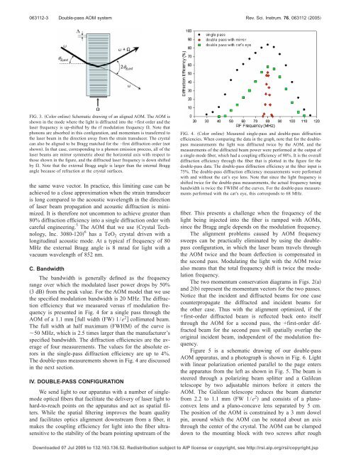
FIG. 3. �Color online� Schematic drawing <strong>of</strong> an aligned AOM. The AOM is<br />
shown in the mode where the light is diffracted into the +first order and the<br />
laser frequency is up-shifted by the rf modulation frequency �. Note that<br />
phonons are absorbed in this configuration, and momentum is transferred to<br />
the laser beam in the direction away from the strain transducer. The crystal<br />
can also be aligned to be Bragg matched for the −first diffraction order �not<br />
shown�. In that case, corresponding to a phonon emission process, all <strong>of</strong> the<br />
laser beams are mirror symmetric about the horizontal axis with respect to<br />
those shown in the figure, and the diffracted laser frequency is down shifted<br />
by �. Note that the external Bragg angle is larger than the internal Bragg<br />
angle because <strong>of</strong> refraction at the crystal surfaces.<br />
the same wave vector. In practice, this limiting case can be<br />
achieved to a close approximation when the strain transducer<br />
is long compared to the acoustic wavelength in the direction<br />
<strong>of</strong> laser beam propagation and acoustic diffraction is minimized.<br />
It is therefore not uncommon to achieve greater than<br />
80% diffraction efficiency into a single diffraction order with<br />
careful engineering. 5 The AOM that we use �Crystal Technology,<br />
Inc. 3080-120� 6 has a TeO 2 crystal driven with a<br />
longitudinal acoustic mode. At a typical rf frequency <strong>of</strong> 80<br />
MHz the external Bragg angle is 8 mrad for light with a<br />
vacuum wavelength <strong>of</strong> 852 nm.<br />
C. Bandwidth<br />
The bandwidth is generally defined as the frequency<br />
range over which the modulated laser power drops by 50%<br />
�3 dB�from the peak value. For the AOM model that we use<br />
the specified modulation bandwidth is 20 MHz. The diffraction<br />
efficiency that we measured versus rf modulation frequency<br />
is presented in Fig. 4 for a single <strong>pass</strong> through the<br />
AOM <strong>of</strong> a 1.1 mm �full width �FW� 1/e2� collimated beam.<br />
The full width at half maximum �FWHM� <strong>of</strong> the curve is<br />
�50 MHz, which is 2.5 times larger than the manufacturer’s<br />
specified bandwidth. The diffraction efficiencies are the average<br />
<strong>of</strong> four measurements. The values for the absolute errors<br />
in the single-<strong>pass</strong> diffraction efficiency are up to 4%.<br />
The double-<strong>pass</strong> measurements shown in Fig. 4 are discussed<br />
in the next section.<br />
IV. DOUBLE-PASS CONFIGURATION<br />
We send light to our apparatus with a number <strong>of</strong> singlemode<br />
<strong>optic</strong>al fibers that facilitate the delivery <strong>of</strong> laser light to<br />
hard-to-reach points on the apparatus and act as spatial filters.<br />
While the spatial filtering improves the beam quality<br />
and facilitates <strong>optic</strong>s alignment downstream from a fiber, it<br />
makes the coupling efficiency for light into the fiber ultrasensitive<br />
to the stability <strong>of</strong> the beam pointing upstream <strong>of</strong> the<br />
FIG. 4. �Color online� Measured single-<strong>pass</strong> and double-<strong>pass</strong> diffraction<br />
efficiencies. When comparing the data in the graph, note that for the double<strong>pass</strong><br />
measurements the light was diffracted twice by the AOM, and the<br />
measurements <strong>of</strong> the diffracted beam power were performed at the output <strong>of</strong><br />
a single-mode fiber, which had a coupling efficiency <strong>of</strong> 80%. It is the overall<br />
diffraction efficiency through the fiber that is plotted in the figure for the<br />
double-<strong>pass</strong> data. The double-<strong>pass</strong> diffraction efficiency at the fiber input is<br />
75%. The double-<strong>pass</strong> diffraction efficiency measurements were performed<br />
with and without the cat’s eye lens. Note that since the light frequency is<br />
shifted twice for the double-<strong>pass</strong> measurements, the actual frequency tuning<br />
bandwidth is twice the FWHM <strong>of</strong> the curves. For the double-<strong>pass</strong> measurements<br />
performed with the cat’s eye, this corresponds to 68 MHz.<br />
fiber. This presents a challenge when the frequency <strong>of</strong> the<br />
light being injected into the fiber is ramped with AOMs,<br />
since the Bragg angle depends on the modulation frequency.<br />
The alignment problems caused by AOM frequency<br />
sweeps can be practically eliminated by using the double<strong>pass</strong><br />
configuration, in which the laser beam travels through<br />
the AOM twice and the beam deflection is compensated in<br />
the second <strong>pass</strong>. Modulating the light with the AOM twice<br />
also means that the total frequency shift is twice the modulation<br />
frequency.<br />
The two momentum conservation diagrams in Figs. 2�a�<br />
and 2�b� represent the momentum vectors for the two <strong>pass</strong>es.<br />
Notice that the incident and diffracted beams for one case<br />
counterpropagate the diffracted and incident beams for<br />
the other case. Thus with the alignment optimized, if the<br />
+first-order diffracted beam is reflected back onto itself<br />
through the AOM for a second <strong>pass</strong>, the +first-order diffracted<br />
beam for the second <strong>pass</strong> will spatially overlap the<br />
original incident beam, independent <strong>of</strong> the modulation frequency.<br />
Figure 5 is a schematic drawing <strong>of</strong> our double-<strong>pass</strong><br />
AOM apparatus, and a photograph is shown in Fig. 6. Light<br />
with linear polarization oriented parallel to the page enters<br />
the apparatus from the left as shown in Fig. 5. The beam is<br />
steered through a polarizing beam splitter and a Galilean<br />
telescope by two adjustable mirrors before it enters the<br />
AOM. The Galilean telescope reduces the beam diameter<br />
from 2.2 to 1.1 mm �FW 1/e 2 � and consists <strong>of</strong> a planoconvex<br />
lens and a plano-concave lens separated by 5 cm.<br />
The position <strong>of</strong> the AOM is constrained by a3mmdowel<br />
pin, around which the AOM can be rotated about an axis<br />
through the center <strong>of</strong> the crystal. The AOM can be clamped<br />
down to the mounting block with two screws after rough<br />
Downloaded 07 Jul 2005 to 132.163.136.52. Redistribution subject to AIP license or copyright, see http://rsi.aip.org/rsi/copyright.jsp