Key features of mixed carbonate-siliciclastic shallow-marine systems ...
Key features of mixed carbonate-siliciclastic shallow-marine systems ...
Key features of mixed carbonate-siliciclastic shallow-marine systems ...

Create successful ePaper yourself
Turn your PDF publications into a flip-book with our unique Google optimized e-Paper software.
KEY FEATURES OF MIXED CARBONATE-SILICICLASTIC SHALLOW-MARINE SYSTEMS 373<br />
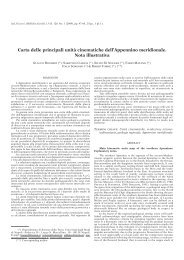
Fig. 4 - The two sections measured along the southern side <strong>of</strong> the Capo Colonna promontory (see fig. 1B for location). These shelf deposits<br />
sharply overlie the Cutro Clay, which represents the substrate <strong>of</strong> the <strong>marine</strong> terrace.<br />
that original, indicating that the terrace has not been<br />
tilted. Such a WRS is associated to a Glossifungites ichn<strong>of</strong>acies<br />
where it truncates the upper part <strong>of</strong> the CC1 cycle<br />
(ZECCHIN et alii, 2009) (fig. 3). Regressive clastic shoreface<br />
deposits pass distally into mostly coralline algal frameworks<br />
and associated calcarenites (NALIN & MASSARI,<br />
2009; ZECCHIN et alii, 2009) (figs. 2-4). The general stratigraphic<br />
architecture <strong>of</strong> both cycles highlights relatively<br />
thin transgressive and thick regressive intervals (fig. 2).<br />
The latter can be top-truncated due to wave ravinement<br />
during a subsequent erosional transgression.<br />
FACIES ANALYSIS OF THE CC2 CYCLE<br />
The CC2 cycle is composed <strong>of</strong> three facies associations<br />
composing a shoreface-shelf depositional system.<br />
According to the sequence stratigraphic interpretation by<br />
ZECCHIN et alii (2009), the sharp surface that marks the<br />
base <strong>of</strong> the cycle, interpreted as a wave-scoured ravine-<br />
ment surface and paved by the deposits <strong>of</strong> facies association<br />
A, erodes both the substrate <strong>of</strong> the terrace (the Cutro<br />
Clay) and the upper shoreface deposits forming part <strong>of</strong><br />
the CC1 cycle (figs. 2 and 3). The boundary between the<br />
facies associations A (below) and B-C (above) is interpreted<br />
as the boundary between transgressive deposits<br />
accumulated during <strong>siliciclastic</strong> starvation (facies association<br />
A) and normal plus forced regressive deposits, i.e. a<br />
maximum flooding surface (figs. 2 and 3). The boundary<br />
between normal and forced regressive deposits is thought<br />
to coincide with the erosional contact between Facies B1<br />
(below) and <strong>shallow</strong>er clastic deposits <strong>of</strong> Facies C1<br />
(above), that is found in distal locations (figs. 2 and 3).<br />
BASAL CONDENSED DEPOSITS (FACIES ASSOCIATION A) - TST<br />
Basal conglomerate (Facies A1)<br />
This facies is locally present at the base <strong>of</strong> the terrace<br />
deposits (Col 10 section, fig. 4), and consists <strong>of</strong> a granule-