

Low Voltage Surge Protection - Powerware
Low Voltage Surge Protection - Powerware
Low Voltage Surge Protection - Powerware

You also want an ePaper? Increase the reach of your titles
YUMPU automatically turns print PDFs into web optimized ePapers that Google loves.
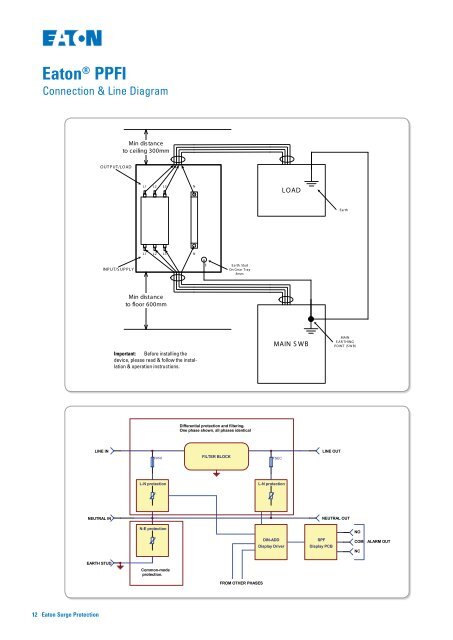
Eaton<br />
Connection & Line Diagram<br />
® PPFI<br />
i S urge Filter<br />
ection Diagram<br />
003C E i, S P F1003DE i, S P F1003E E i,<br />
0C E i, S P F150DE i, S P F150E E i,<br />
0C E i, S P F200DE i, S P F200E E i,<br />
50C E i, S P F250DE i, S P F250E E i<br />
ment is to be us ed in conjunction with<br />
S urge Filter Ins tallation G uide<br />
(Tvs s Doc#510063)<br />
utral connections via 8mm bolts.<br />
via M8 stud, lower right of enclosure.<br />
for connection points.<br />
arate earth cable, even if the unit is bolted to<br />
utput cables physically separated at all times.<br />
istance 500mm.<br />
referred to MC Bs for connection to main S W B.<br />
stallation guide for details.<br />
ted within 3m (cable length) of the main system<br />
l link for point-of-entry application. G reater<br />
rotection.<br />
proper operation of this S PF it is essential that<br />
sically short earth connection be made to the<br />
t. W ith reference to local wiring standards,<br />
usually sized against a thermal rating,<br />
pected fault currents, (5,000 to 25,000 amps).<br />
n S P F however, the installer must be aware<br />
ts can exceed 50,000 amps, and therefore<br />
e generally required to limit voltage drops<br />
itions. T o achieve these requirements, the<br />
hould be selected to be equal to, or greater<br />
incoming cable into the S PF. This ensures that<br />
the earth cable are minimised.<br />
ower-carrying conductors shall be sized<br />
lly-applicable standards. It is recommended<br />
neutral conductor be sized the same as (or<br />
hase conducts as it is the primary return for<br />
s.<br />
D<br />
C<br />
B<br />
A<br />
3/2/2005<br />
12 Eaton <strong>Surge</strong> <strong>Protection</strong><br />
OUT P UT/LOAD<br />
1<br />
LINE IN<br />
INP UT/S UP P LY<br />
LC<br />
NEUTRAL IN<br />
EARTH STUD<br />
K<br />
CMY<br />
CY<br />
Min distance<br />
to ceiling 300mm<br />
L1 L2 L3<br />
L1 L2 L3 N<br />
Min distance<br />
to floor 600mm<br />
Important: Before installing the<br />
device, please read & follow the installation<br />
& operation instructions.<br />
FPRI<br />
L-N protection<br />
N-E protection<br />
Common-mode<br />
protection.<br />
MY<br />
CM<br />
Y<br />
2<br />
N<br />
M<br />
3/2/2005<br />
C<br />
E Earth Stud<br />
On G ear Tray<br />
8mm<br />
K<br />
Differential protection and filtering.<br />
One phase shown, all phases identical<br />
CMY<br />
FILTER BLOCK<br />
CY<br />
MY<br />
LOAD<br />
MAIN S WB<br />
Earth<br />
MAIN<br />
E AR THING<br />
POINT (S W B)<br />
S P F i S eries<br />
1 2 3<br />
4<br />
CM<br />
Y<br />
FROM OTHER PHASES<br />
M<br />
C<br />
FSEC<br />
L-N protection<br />
DIN-ADD<br />
Display Driver<br />
3<br />
Title<br />
SPF<br />
LINE OUT<br />
Display PCB<br />
NEUTRAL OUT<br />
NO<br />
550193<br />
COM<br />
NC<br />
SPF FILTER LINE DIAGRAM<br />
Size<br />
A4<br />
Number<br />
550246<br />
Revision<br />
0<br />
Date:<br />
File:<br />
7-Aug-2006<br />
Shee1<br />
t of1<br />
C:\tvss engineering\Product_engineering\current\MSF\MSF.ddb<br />
Drawn By: JDP<br />
4<br />
ALARM OUT<br />
D<br />
C<br />
B<br />
A