

Comparison of the Different Anode Technologies Used in Thermal ...
Comparison of the Different Anode Technologies Used in Thermal ...
Comparison of the Different Anode Technologies Used in Thermal ...

Create successful ePaper yourself
Turn your PDF publications into a flip-book with our unique Google optimized e-Paper software.
voltage (V)<br />
30<br />
25<br />
20<br />
15<br />
10<br />
5<br />
0<br />
LiAl @ 490°C 2.2<br />
LiAl @ 575°C 2.2A<br />
LiSi @ 490°C 2.2A<br />
LiSi @ 575°C 2.2A<br />
LAN @ 490°C 2.2A<br />
LAN @ 575°C 2.2A<br />
0 200 400 600 800 1000 1200<br />
time (s)<br />
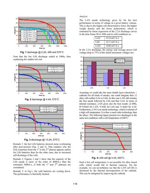
Fig. 1 discharge @ 2.2A, 490 and 575°C<br />
Note that <strong>the</strong> hot LiSi discharge ended at 1000s, thus<br />
expla<strong>in</strong><strong>in</strong>g <strong>the</strong> sudden tail end<br />
voltage (V)<br />
voltage (V)<br />
30<br />
25<br />
20<br />
15<br />
10<br />
5<br />
0<br />
30<br />
25<br />
20<br />
15<br />
10<br />
5<br />
0<br />
LiAl @ 575°C 4.4A<br />
LiSi @ 575°C 4.4A<br />
LAN @ 575°C 4.4A<br />
0 200 400 600 800 1000 1200<br />
time (s)<br />
Fig. 2 discharge @ 4.4A, 575°C<br />
LiAl @ 575°C 13.2A<br />
LiSi @ 575°C 13.2A<br />
LAN @ 590°C 13.2A<br />
0 100 200 300 400 500 600<br />
time (s)<br />
Fig. 3 discharge @ 13.2A, 575°C<br />
Remark 1: <strong>the</strong> hot LiSi batteries showed some overheat<strong>in</strong>g<br />
after post-mortem (Fig. 2 and 3). That expla<strong>in</strong>s why <strong>the</strong><br />
FeS2 transition from <strong>the</strong> 1 st to <strong>the</strong> 2 nd plateau appears earlier<br />
for LiSi batteries than for <strong>the</strong> o<strong>the</strong>r ones, due to <strong>in</strong>creased<br />
self-discharge <strong>of</strong> <strong>the</strong> cells.<br />
Remark 2: Figures 2 and 3 show that <strong>the</strong> capacity <strong>of</strong> <strong>the</strong><br />
LiSi anode is more <strong>of</strong> <strong>the</strong> order <strong>of</strong> 4000A-s than <strong>the</strong><br />
estimated 3600A-s, if both <strong>the</strong> 1 st and 2 nd plateaus are<br />
considered.<br />
Remark 3: <strong>in</strong> Fig.1, <strong>the</strong> cold batteries are cool<strong>in</strong>g down.<br />
The performance is <strong>the</strong>rmally limited.<br />
118<br />
Analysis<br />
The LAN anode technology gives by far <strong>the</strong> best<br />
performance <strong>in</strong> terms <strong>of</strong> voltage <strong>in</strong> a given battery volume.<br />
This is due to <strong>the</strong> higher cell electromotive force, <strong>the</strong> higher<br />
weight density and <strong>the</strong> lower polarization, which is<br />
estimated by l<strong>in</strong>ear regression <strong>of</strong> <strong>the</strong> 2.2A discharge curves<br />
<strong>in</strong> <strong>the</strong> time frame 80 to 500s and <strong>in</strong> cold conditions as:<br />
LiAl -0.14 mV/A-s<br />
LiSi -0.11 mV/A-s<br />
LAN -0.08 mV/A-s<br />
In <strong>the</strong> 2.2A discharge, <strong>the</strong> energy and average power (till<br />
voltage drop to 75% <strong>of</strong> <strong>the</strong> <strong>in</strong>itial maximum voltage) are:<br />
70<br />
60<br />
50<br />
40<br />
30<br />
20<br />
10<br />
0<br />
Energy (kJ)<br />
Power (W)<br />
LAN LiAl LiSi<br />
Assum<strong>in</strong>g we could take <strong>the</strong> same double layer (electrolyte +<br />
cathode) for all k<strong>in</strong>ds <strong>of</strong> anodes, one could <strong>in</strong>tegrate <strong>the</strong>n 12<br />
alloy cells (ei<strong>the</strong>r LiAl or LiSi). In this case LAN still rema<strong>in</strong>s<br />
<strong>the</strong> best anode followed by LiSi and <strong>the</strong>n LiAl. In terms <strong>of</strong><br />
<strong>in</strong>ternal resistance, LAN gives also <strong>the</strong> best results: at 600s,<br />
R=9.0mΩ for LAN, 9.3mΩ for LiSi and 11.6mΩ for LiAl.<br />
Fur<strong>the</strong>rmore, LAN is an anode technology, which is tolerant <strong>of</strong><br />
a high cell temperature. It is thus a much safer technology than<br />
<strong>the</strong> alloys. The follow<strong>in</strong>g figure presents two discharges <strong>in</strong> <strong>the</strong><br />
same test conditions with a cell temperature <strong>of</strong> 640°C.<br />
voltage (V)<br />
30<br />
25<br />
20<br />
15<br />
10<br />
5<br />
0<br />
LAN @ 640°C 4.4A<br />
LAN @ 640°C 4.4A<br />
0 100 200 300 400 500 600<br />
time (s)<br />
Fig. 4 LAN cell @ 4.4A, 640°C<br />
Such a hot cell temperature is not possible for alloy based<br />
cells, which would fail <strong>in</strong> <strong>the</strong>rmal runaway. On <strong>the</strong><br />
example, we can never<strong>the</strong>less see that <strong>the</strong> LAN cell life is<br />
shortened by <strong>the</strong> <strong>the</strong>rmal decomposition <strong>of</strong> <strong>the</strong> cathode.<br />
This can be mitigated by improv<strong>in</strong>g <strong>the</strong> cathode.