DS 7-76 Prevention and Mitigation of Combustible Dust ... - FM Global
DS 7-76 Prevention and Mitigation of Combustible Dust ... - FM Global
DS 7-76 Prevention and Mitigation of Combustible Dust ... - FM Global

Create successful ePaper yourself
Turn your PDF publications into a flip-book with our unique Google optimized e-Paper software.
<strong>FM</strong> <strong>Global</strong><br />
Property Loss <strong>Prevention</strong> Data Sheets 7-<strong>76</strong><br />
January 2012<br />
Page 1 <strong>of</strong> 56<br />
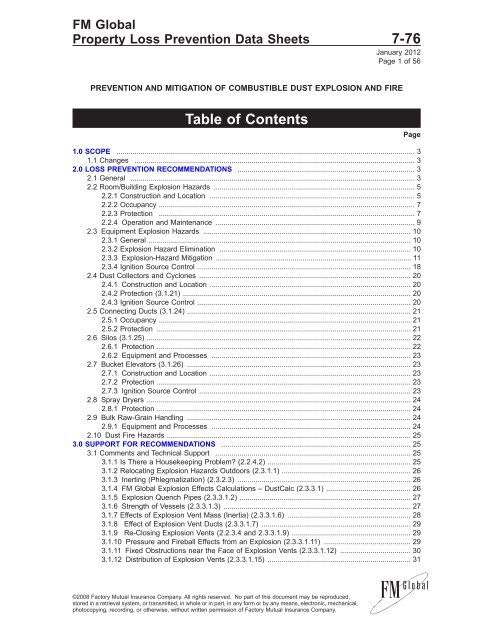
PREVENTION AND MITIGATION OF COMBUSTIBLE DUST EXPLOSION AND FIRE<br />
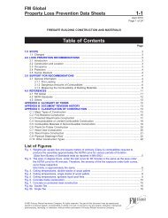
Table <strong>of</strong> Contents<br />
1.0 SCOPE .................................................................................................................................................... 3<br />
1.1 Changes ........................................................................................................................................... 3<br />
2.0 LOSS PREVENTION RECOMMENDATIONS ........................................................................................ 3<br />
2.1 General ............................................................................................................................................. 3<br />
2.2 Room/Building Explosion Hazards .................................................................................................... 5<br />
2.2.1 Construction <strong>and</strong> Location ...................................................................................................... 5<br />
2.2.2 Occupancy ............................................................................................................................... 7<br />
2.2.3 Protection ............................................................................................................................... 7<br />
2.2.4 Operation <strong>and</strong> Maintenance ................................................................................................... 9<br />
2.3 Equipment Explosion Hazards ....................................................................................................... 10<br />
2.3.1 General .................................................................................................................................. 10<br />
2.3.2 Explosion Hazard Elimination ............................................................................................... 10<br />
2.3.3 Explosion-Hazard <strong>Mitigation</strong> ................................................................................................. 11<br />
2.3.4 Ignition Source Control .......................................................................................................... 18<br />
2.4 <strong>Dust</strong> Collectors <strong>and</strong> Cyclones ......................................................................................................... 20<br />
2.4.1 Construction <strong>and</strong> Location .................................................................................................... 20<br />
2.4.2 Protection (3.1.21) ................................................................................................................. 20<br />
2.4.3 Ignition Source Control .......................................................................................................... 20<br />
2.5 Connecting Ducts (3.1.24) ............................................................................................................... 21<br />
2.5.1 Occupancy ............................................................................................................................. 21<br />
2.5.2 Protection .............................................................................................................................. 21<br />
2.6 Silos (3.1.25) ................................................................................................................................... 22<br />
2.6.1 Protection .............................................................................................................................. 22<br />
2.6.2 Equipment <strong>and</strong> Processes ................................................................................................... 23<br />
2.7 Bucket Elevators (3.1.26) ............................................................................................................... 23<br />
2.7.1 Construction <strong>and</strong> Location .................................................................................................... 23<br />
2.7.2 Protection .............................................................................................................................. 23<br />
2.7.3 Ignition Source Control ......................................................................................................... 23<br />
2.8 Spray Dryers ................................................................................................................................... 24<br />
2.8.1 Protection .............................................................................................................................. 24<br />
2.9 Bulk Raw-Grain H<strong>and</strong>ling ............................................................................................................... 24<br />
2.9.1 Equipment <strong>and</strong> Processes ................................................................................................... 24<br />
2.10 <strong>Dust</strong> Fire Hazards ......................................................................................................................... 25<br />
3.0 SUPPORT FOR RECOMMENDATIONS .............................................................................................. 25<br />
3.1 Comments <strong>and</strong> Technical Support ................................................................................................. 25<br />
3.1.1 Is There a Housekeeping Problem? (2.2.4.2) ....................................................................... 25<br />
3.1.2 Relocating Explosion Hazards Outdoors (2.3.1.1) ................................................................ 26<br />
3.1.3 Inerting (Phlegmatization) (2.3.2.3) ...................................................................................... 26<br />
3.1.4 <strong>FM</strong> <strong>Global</strong> Explosion Effects Calculations – <strong>Dust</strong>Calc (2.3.3.1) .......................................... 26<br />
3.1.5 Explosion Quench Pipes (2.3.3.1.2) ..................................................................................... 27<br />
3.1.6 Strength <strong>of</strong> Vessels (2.3.3.1.3) ............................................................................................. 27<br />
3.1.7 Effects <strong>of</strong> Explosion Vent Mass (Inertia) (2.3.3.1.6) ............................................................. 28<br />
3.1.8 Effect <strong>of</strong> Explosion Vent Ducts (2.3.3.1.7) .......................................................................... 29<br />
3.1.9 Re-Closing Explosion Vents (2.2.3.4 <strong>and</strong> 2.3.3.1.9) ........................................................... 29<br />
3.1.10 Pressure <strong>and</strong> Fireball Effects from an Explosion (2.3.3.1.11) ........................................... 29<br />
3.1.11 Fixed Obstructions near the Face <strong>of</strong> Explosion Vents (2.3.3.1.12) ................................... 30<br />
3.1.12 Distribution <strong>of</strong> Explosion Vents (2.3.3.1.15) ....................................................................... 31<br />
©2008 Factory Mutual Insurance Company. All rights reserved. No part <strong>of</strong> this document may be reproduced,<br />
stored in a retrieval system, or transmitted, in whole or in part, in any form or by any means, electronic, mechanical,<br />
photocopying, recording, or otherwise, without written permission <strong>of</strong> Factory Mutual Insurance Company.<br />
Page
7-<strong>76</strong> <strong>Combustible</strong> <strong>Dust</strong> Explosion<br />
Page 2 <strong>FM</strong> <strong>Global</strong> Property Loss <strong>Prevention</strong> Data Sheets<br />
3.1.13 <strong>Dust</strong> Collector Operating Pressures (2.3.3.1.17) ............................................................... 31<br />
3.1.14 Explosion Isolation (2.3.3.2) .............................................................................................. 31<br />
3.1.15 Explosion Isolation: Use <strong>of</strong> Active Devices (2.3.3.3.4) ...................................................... 31<br />
3.1.16 Rapid-Action Float Valves (2.3.3.3.5) .................................................................................. 32<br />
3.1.17 Vacuum Operation (2.3.3.6) ............................................................................................... 32<br />
3.1.18 Spark Extinguishing Versus Explosion Suppression (2.3.4.1) ........................................... 32<br />
3.1.19 Minimum Ignition Energy (MIE)(2.3.4.2) ............................................................................. 33<br />
3.1.20 Foreign Material Separators, Magnetic or Other (2.3.4.3) ................................................. 33<br />
3.1.21 Clean Versus Dirty Side <strong>of</strong> <strong>Dust</strong> Collectors (2.4.2) ............................................................ 33<br />
3.1.22 Cyclone Explosion Venting (2.4.2.3) .................................................................................. 34<br />
3.1.23 ‘‘Conductive’’ <strong>Dust</strong> Collector Bags (2.4.3.1) ....................................................................... 34<br />
3.1.24 Connecting Ducts (2.5) ....................................................................................................... 34<br />
3.1.25 Silos (2.6) ............................................................................................................................ 35<br />
3.1.26 Bucket Elevators (2.7) ......................................................................................................... 35<br />
3.1.27 Size-Reduction Equipment (Grinders, Pulverizers, Hammer Mills, etc.) ............................ 36<br />
3.2 Loss History ..................................................................................................................................... 36<br />
4.0 REFERENCES ...................................................................................................................................... 38<br />
4.1 <strong>FM</strong> <strong>Global</strong> ....................................................................................................................................... 38<br />
4.2 Other ................................................................................................................................................ 38<br />
APPENDIX A GLOSSARY OF TERMS ...................................................................................................... 39<br />
APPENDIX B DOCUMENT REVISION HISTORY ...................................................................................... 41<br />
APPENDIX C RESEARCH INFORMATION ON DUST EXPLOSION HAZAR<strong>DS</strong> ...................................... 42<br />
C.1 Reprint from Journal <strong>of</strong> Loss <strong>Prevention</strong> in the Process Industries: Improved Guidelines for<br />
the Sizing <strong>of</strong> Vents in <strong>Dust</strong> Explosions .......................................................................................... 42<br />
APPENDIX D BIBLIOGRAPHY ................................................................................................................... 56<br />
List <strong>of</strong> Figures<br />
Fig. 1. Preferred locations for processes or equipment h<strong>and</strong>ling combustible dusts ................................... 6<br />
Fig. 2. Schematic <strong>of</strong> ro<strong>of</strong>top explosion vents that project above the ro<strong>of</strong> line ............................................. 8<br />
Fig. 3. Rotary Air Lock ................................................................................................................................. 14<br />
Fig. 4. Rapid-action valve (gate type) ......................................................................................................... 15<br />
Fig. 5. Rapid action float valve (Ventix ESI ®) ............................................................................................ 15<br />
Fig. 6. Acceptable design parameters for explosion diverters .................................................................... 16<br />
Fig. 7. Explosion diverter .............................................................................................................................. 17<br />
Fig. 8. Indoor installation <strong>of</strong> explosion diverter ............................................................................................ 17<br />
Fig. 9. High-speed abort gate ...................................................................................................................... 17<br />
Fig. 10. Example <strong>of</strong> duct explosion venting at an elbow ............................................................................ 22<br />
Fig. 11. <strong>FM</strong> Approved explosion quench pipe (Photo courtesy <strong>of</strong> Rembe GmbH) ................................... 28<br />
List <strong>of</strong> Tables<br />
Table 1. Construction for <strong>Dust</strong> H<strong>and</strong>ling Occupancies ................................................................................... 6<br />
Table 2. Typical <strong>Dust</strong> Bulk Density .............................................................................................................. 26<br />
Table 3. Losses by Industry (by Number <strong>of</strong> Losses) ................................................................................... 36<br />
Table 4. Losses by Cause (Ignition Source) ................................................................................................ 37<br />
Table 5. Losses by <strong>Dust</strong> Type ...................................................................................................................... 37<br />
Table 6. Losses by Equipment Type ............................................................................................................ 38<br />
©2008 Factory Mutual Insurance Company. All rights reserved.
<strong>Combustible</strong> <strong>Dust</strong> Explosion 7-<strong>76</strong><br />
<strong>FM</strong> <strong>Global</strong> Property Loss <strong>Prevention</strong> Data Sheets Page 3<br />
1.0 SCOPE<br />
This data sheet describes recommended preventive measures to reduce the frequency <strong>of</strong> combustible dust<br />
explosions, <strong>and</strong> protection features to minimize damage from a combustible dust explosion. The hazards<br />
<strong>of</strong> dust fires can be found in other data sheets containing detailed occupancyspecific recommendations.<br />
However, an overview <strong>of</strong> loss history related to dust fires is included in this document.<br />
This data sheet does not include dust explosion prevention <strong>and</strong> protection schemes unique to grain h<strong>and</strong>ling,<br />
storage, <strong>and</strong> processing. Loss prevention recommendations for these occupancies are covered in Data Sheet<br />
7-75, Grain Storage <strong>and</strong> Milling. However, recommendations in this data sheet do apply to hazards at grain<br />
h<strong>and</strong>ling facilities that are not unique to those facilities.<br />
The technology <strong>of</strong> dust explosion hazard evaluation is primarily discussed in metric (SI) units <strong>and</strong> those are<br />
the units used in this data sheet.<br />
1.1 Changes<br />
January 2012. Terminology related to ignitable liquids has been revised to provide increased clarity <strong>and</strong><br />
consistency with regard to <strong>FM</strong> <strong>Global</strong>’s loss prevention recommendations for ignitable liquid hazards.<br />
2.0 LOSS PREVENTION RECOMMENDATIONS<br />
2.1 General<br />
2.1.1 Treat all equipment that h<strong>and</strong>les combustible dusts, as well as any rooms or buildings where combustible<br />
dusts can be present <strong>and</strong> might be put into suspension, as having a dust explosion hazard.<br />
2.1.2 Implement a management-<strong>of</strong>-change process in all facilities h<strong>and</strong>ling combustible dusts to be certain<br />
that no changes occur that could increase the severity or consequence <strong>of</strong> an existing dust hazard or introduce<br />
a dust hazard where none previously existed. Examples <strong>of</strong> such changes include the following:<br />
• Adding new equipment such as blenders, grinders, cutting tools, dust collectors, cyclones, etc.<br />
• Increasing temperatures in the process that could result in drier material being h<strong>and</strong>led<br />
• Adding new materials<br />
• Changing product formulation by adding combustible materials or reducing the proportion <strong>of</strong> inert materials<br />
• Making process changes that reduce the particle size <strong>of</strong> in-process materials<br />
2.1.3 Where process, equipment, raw material, or product changes are planned that could significantly change<br />
the dust properties, retest the dust for its explosibility.<br />
2.1.4. Ensure your management-<strong>of</strong>-change process has the following minimum characteristics:<br />
a) Provides a method for identification <strong>of</strong> changes that should be subject to the management-<strong>of</strong>-change<br />
process<br />
b) Provides documentation <strong>of</strong> the proposed change<br />
c) Provides a formal analysis <strong>of</strong> the loss prevention considerations involved in the proposed change<br />
d) Identifies the need for updated personnel training<br />
e) Provides for communication <strong>of</strong> the change <strong>and</strong> the loss prevention consequences to appropriate<br />
personnel such as maintenance, operators, safety, <strong>and</strong> emergency responders<br />
f) Establishes any administrative procedures needed (documentation, checklists that cover hazards,<br />
training, etc.)<br />
g) Identifies any required authorizations<br />
2.1.5 Where potential for a dust explosion exists, eliminate the potential or minimize the consequences using<br />
one <strong>of</strong> the following methods:<br />
a) Control fugitive dust releases using enclosures, collection systems <strong>and</strong> equipment design.<br />
©2008 Factory Mutual Insurance Company. All rights reserved.
7-<strong>76</strong> <strong>Combustible</strong> <strong>Dust</strong> Explosion<br />
Page 4 <strong>FM</strong> <strong>Global</strong> Property Loss <strong>Prevention</strong> Data Sheets<br />
b) Locate dust producing operations in areas separated from different hazard occupancies by construction<br />
(dust-tight <strong>and</strong> explosion-resistant barriers) or distance.<br />
c) Minimize chances for dust accumulation by arranging building elements <strong>and</strong> equipment to reduce the<br />
likelihood <strong>of</strong> dust accumulations. Employ features such as smooth, easily cleaned walls, boxed in or<br />
covered horizontal surfaces (beams, joists, etc.), <strong>and</strong> surfaces sloped a minimum <strong>of</strong> 60° from the<br />
horizontal.<br />
d) Where fugitive dust release <strong>and</strong> accumulation exist in buildings, design the structure to safely vent<br />
the potential explosion using damage-limiting construction.<br />
e) Locate dust collection <strong>and</strong> transfer equipment outside, away from important buildings <strong>and</strong> utilities.<br />
f) Construct equipment that processes or transfers combustible particles to contain or safely vent a<br />
potential explosion.<br />
g) Where explosion venting or containment in equipment is not possible, eliminate the oxygen in the system<br />
by inerting, or install an explosion-suppression system.<br />
2.1.6 Practice effective maintenance <strong>of</strong> production <strong>and</strong> protection equipment. An effective maintenance<br />
program will:<br />
a) Identify <strong>and</strong> eliminate fugitive dust sources continually.<br />
b) Test <strong>and</strong> maintain spark detection <strong>and</strong> extinguishing systems, explosion isolation devices, <strong>and</strong> relief<br />
vents to ensure they are in working order per manufacturer’s guidelines, or at least monthly.<br />
c) Test <strong>and</strong> maintain metal <strong>and</strong> non-metal detection <strong>and</strong> extraction equipment to ensure they are in working<br />
order, at least quarterly.<br />
d) Check belts <strong>and</strong> rotating equipment for alignment at least quarterly to prevent these becoming a source<br />
<strong>of</strong> friction heating.<br />
e) Lubricate bearings <strong>and</strong> rotating equipment (fans, blowers, size-reduction equipment) in accordance<br />
with manufacturer’s guidelines, or at least quarterly<br />
f) Remove accumulated dust on rotating equipment bearings <strong>and</strong> components to insure free movement<br />
<strong>and</strong> prevent friction heating, at least quarterly.<br />
g) Assign accountability <strong>and</strong> keep accurate records.<br />
2.1.7 Ensure a comprehensive dust fire <strong>and</strong> explosion awareness program exists at all sites where<br />
combustible dust exists either within closed processing systems or as fugitive dust within buildings. Include<br />
the following:<br />
a) Basic education to promote awareness <strong>and</strong> underst<strong>and</strong>ing <strong>of</strong> the hazards <strong>of</strong> combustible dusts<br />
b) Instruction <strong>of</strong> new employees on the particular hazards <strong>and</strong> on precautions relevant to their departments<br />
c) A minimum <strong>of</strong> annual instruction, drill, <strong>and</strong> familiarization <strong>of</strong> the local public fire service <strong>and</strong>/or internal<br />
firefighting teams<br />
d) Periodic refresher training for all facility personnel<br />
2.1.8 Strictly control potential dust ignition sources where combustible dusts may be present.<br />
a) Ensure all electrical equipment is rated Class II, Division 1 or 2, or Zone 20, 21, or 22 per NFPA 70,<br />
the National Electric Code, Articles 500, 502, <strong>and</strong> 506, as appropriate, or international equivalent. (Refer<br />
to Data Sheet 5-1, Electrical Equipment in Hazardous Locations, for additional details regarding area<br />
classification <strong>and</strong> equipment selection.)<br />
b) Use a hot work permit system to manage all hot work operations. (See <strong>DS</strong> 10-3, Hot Work Management,<br />
<strong>and</strong> Hot Work Management Kit, P9601)<br />
c) Prohibit smoking <strong>and</strong> open flames.<br />
d) Provide grounding <strong>and</strong> bonding <strong>of</strong> metal components with a resistance <strong>of</strong> less than 1 x 10 6 ohms to<br />
ground. (See <strong>DS</strong> 5-8, Static Electricity.) At least annually, check for continuity <strong>of</strong> the metal components <strong>and</strong><br />
security <strong>of</strong> any bonding connections.<br />
©2008 Factory Mutual Insurance Company. All rights reserved.
<strong>Combustible</strong> <strong>Dust</strong> Explosion 7-<strong>76</strong><br />
<strong>FM</strong> <strong>Global</strong> Property Loss <strong>Prevention</strong> Data Sheets Page 5<br />
e) Subject all electrical equipment to an initial infrared (IR) scan <strong>and</strong> then at a frequency as dictated by<br />
results <strong>and</strong> <strong>DS</strong> 5-20, Electrical Testing.<br />
2.1.9 Prohibit recycling <strong>of</strong> air material separator exhaust to buildings or rooms, except where either “a” or<br />
all <strong>of</strong> “b through h” apply:<br />
a) The return air duct discharges into an area that does not contain fugitive dust, combustible equipment<br />
or storage, combustible construction, high-value equipment, or equipment that is critical to production,<br />
OR<br />
b) Install a filter downstream <strong>of</strong> the dust air separators that prevents return <strong>of</strong> dust to the enclosure with<br />
a minimum efficiency <strong>of</strong> 99.9% at 10 microns AND<br />
c) Install a device to measure pressure-drop across the filter with an alarm to indicate when the filter needs<br />
to be cleaned or replaced AND<br />
d) Provide support for the filter with a wire mesh screen or other method that allows the filter to withst<strong>and</strong><br />
a pressure equal to or exceeding the value <strong>of</strong> P red for the piece <strong>of</strong> equipment directly upstream from it<br />
AND<br />
e) Provide explosion isolation between the building <strong>and</strong> the last dust collector in the system (the one<br />
furthest downstream) AND<br />
f) On explosion-isolation system activation, shut down any connected dust- collection equipment AND<br />
g) Ignitable vapors, gases, or hybrid mixtures are not involved AND<br />
h) The dust-collection system meets the protection requirements in other sections <strong>of</strong> this data sheet.<br />
Where these features are present, the recycling <strong>of</strong> air material separator exhaust would not cause the<br />
building/room to require explosion protection features such as venting, etc. (other factors present in the<br />
building/room could create that need, however).<br />
2.2 Room/Building Explosion Hazards<br />
2.2.1 Construction <strong>and</strong> Location<br />
Isolate areas h<strong>and</strong>ling combustible dusts from other less hazardous occupancies by separation with<br />
construction or distance to minimize damage from the potential explosion or fire. Areas needing isolation<br />
would be where fugitive dust is not readily controlled for example, grinding, s<strong>and</strong>ing, sawing, open conveying,<br />
filing open bins, etc. Excluded would be for example, rooms containing properly vented dust collectors, spray<br />
dryers, fluid bed dryers, etc.<br />
In new construction where some fugitive dust is likely, maximizing explosion venting beyond that calculated<br />
by <strong>Dust</strong>Calc, can provide future flexibility for process or material changes, <strong>and</strong> <strong>of</strong>ten can be done with little<br />
additional cost.<br />
2.2.1.1 Isolate areas h<strong>and</strong>ling combustible dusts using the methods listed below in order <strong>of</strong> preference (also<br />
see Figure 1, Table 1):<br />
a) Detached outside location at least 50 ft (15 m) away from an important building or facility (Fig. 1,<br />
Location 1)<br />
b) Along an exterior wall <strong>of</strong> an important building, preferably at a corner to limit exposure (Fig. 1, Location 2)<br />
c) Inside an important building on the first floor, either at an exterior corner or along an exterior wall. Avoid<br />
locations on upper floors <strong>of</strong> multistory buildings. Where above-grade locations are unavoidable, ensure<br />
the floor <strong>and</strong> ceiling <strong>of</strong> the room have the same pressure resistance as the walls. (Fig. 1, Locations<br />
3 <strong>and</strong> 4)<br />
Where confirmed using <strong>Dust</strong>Calc s<strong>of</strong>tware, the spacing can be reduced to less than recommended in ″a″<br />
above or Distance X in Table 1.<br />
©2008 Factory Mutual Insurance Company. All rights reserved.
7-<strong>76</strong> <strong>Combustible</strong> <strong>Dust</strong> Explosion<br />
Page 6 <strong>FM</strong> <strong>Global</strong> Property Loss <strong>Prevention</strong> Data Sheets<br />
2.2.1.2 Avoid below-grade locations that cannot be equipped with adequate explosion venting.<br />
Fig. 1. Preferred locations for processes or equipment h<strong>and</strong>ling combustible dusts<br />
Table 1. Construction for <strong>Dust</strong> H<strong>and</strong>ling Occupancies<br />
Room/Building Construction Construction <strong>of</strong> Exposed Wall<br />
Location Distance X, ft (m) A B Ro<strong>of</strong><br />
C<br />
1 (note 3) > 50 (15) PV PV PV or LW Any<br />
10 – 50<br />
(3 – 15)<br />
PR PV PV or LW Any<br />
< 10 (3) PR PV PV or LW PR for 10 ft (3 m),<br />
horizontally & vertically<br />
beyond exposing structure<br />
2 Abutting DNA B B* PV or LW PR for 10 ft (3 m),<br />
PV PV<br />
horizontally & vertically<br />
beyond abutting structure<br />
Abutting DNA B B* PR PR for 10 ft (3 m),<br />
PV PV<br />
horizontally beyond<br />
abutting structure<br />
Abutting DNA B B* PR PR for Abutting wall only<br />
PV PR<br />
3 (note 5) Inside PV PR PR DNA<br />
4 (note 5) Inside PV PR PR DNA<br />
1. This table addresses only protection against explosion hazard.<br />
2. The types <strong>of</strong> construction are defined as follows:<br />
PR = Pressure resistant<br />
PV = Pressure venting<br />
LW = Lightweight, noncombustible<br />
3. Where confirmed with calculations by the <strong>Dust</strong>Calc s<strong>of</strong>tware, location 1 distance X may be less than those listed above.<br />
4. PR construction is also needed for floors <strong>and</strong> ceilings that have spaces below or above that contain less-hazardous occupancies.<br />
5. Where adequate venting can be provided using the walls alone, ro<strong>of</strong>s (not ceilings) do not need to be pressure-venting.<br />
2.2.1.3 Construct buildings in which a combustible dust hazard exists <strong>of</strong> noncombustible or <strong>FM</strong> Approved<br />
Class 1 materials.<br />
2.2.1.4 Ensure physical barriers that isolate dust hazard areas are sealed dust tight using noncombustible<br />
materials. Where the barriers have a fire resistance, ensure the seals maintain that rating.<br />
2.2.1.5 Use door seals, window seals, positive room pressurization, etc. to prevent dust from entering <strong>and</strong><br />
accumulating in adjacent areas that otherwise do not have their own sources <strong>of</strong> fugitive dust.<br />
2.2.1.6 Ensure physical barriers that isolate dust hazard areas have explosion resistance sufficient to prevent<br />
failure before the pressure can be safely vented.<br />
2.2.1.7 Do not allow openings in explosion-resistant walls. Where openings cannot be avoided, keep all doors<br />
in these walls normally closed <strong>and</strong> make sure they have the same explosion-resistance as the walls<br />
themselves. (See <strong>DS</strong> 1-44, Damage-Limiting Construction, for design <strong>and</strong> installation <strong>of</strong> explosion resistant<br />
doors <strong>and</strong> windows.)<br />
©2008 Factory Mutual Insurance Company. All rights reserved.
<strong>Combustible</strong> <strong>Dust</strong> Explosion 7-<strong>76</strong><br />
<strong>FM</strong> <strong>Global</strong> Property Loss <strong>Prevention</strong> Data Sheets Page 7<br />
2.2.1.8 Provide pressure resistance <strong>and</strong> vent area in accordance with calculations conducted using <strong>FM</strong> <strong>Global</strong><br />
<strong>Dust</strong>Calc s<strong>of</strong>tware.<br />
2.2.1.9 In buildings where some fugitive dust is likely despite process design <strong>and</strong> equipment upkeep, arrange<br />
building elements <strong>and</strong> equipment to reduce the likelihood <strong>and</strong> amount <strong>of</strong> dust accumulation by any or all<br />
<strong>of</strong> the following, as appropriate:<br />
a) Provide smooth interior walls with minimal ledges.<br />
b) To the extent practical, provide horizontal surfaces such as girders, beams, ledges, <strong>and</strong> equipment<br />
tops with a sloped cover having a smooth finish, to shed dust settling out <strong>of</strong> the air.<br />
c) Slope covers at an angle <strong>of</strong> 60° from horizontal, unless a lesser slope is known to be sufficient.<br />
d) Box in overhead structural steel that is out <strong>of</strong> the reach <strong>of</strong> normal vacuuming or sweeping operations<br />
<strong>and</strong> that has horizontal ledges (such as Ibeams or Ushaped channels in the up or sideways position)<br />
with a noncombustible material to eliminate pockets for dust accumulation.<br />
2.2.2 Occupancy<br />
2.2.2.1 Buildings can be considered as not having a combustible dust hazard if they contain combustible<br />
dust-h<strong>and</strong>ling equipment that is designed <strong>and</strong> protected to control or safely vent an internal explosion, in<br />
accordance with the pertinent sections <strong>of</strong> this data sheet.<br />
2.2.2.2 Take any or all <strong>of</strong> the following steps, as needed, where quantities <strong>of</strong> fugitive dust could be expected<br />
in new operations or are excessive in existing operations:<br />
a) Survey process equipment to identify the sources <strong>of</strong> dust release.<br />
b) Modify, repair, or replace equipment to eliminate or at least reduce dust escape.<br />
c) Provide permanent vacuum pickup points at the locations that release dust, such as grinding, buffing,<br />
bag dumping, open transfer points in conveying systems, <strong>and</strong> other equipment/locations where large<br />
quantities <strong>of</strong> dust are liberated frequently. In some cases this may require construction <strong>of</strong> a ventilated hood<br />
or containment enclosure for existing equipment.<br />
d) Operate closed dust-h<strong>and</strong>ling systems under a slight negative pressure to reduce dust escape.<br />
e) Conduct extra housekeeping in existing operations while equipment is being modified (see Section<br />
2.2.4).<br />
2.2.2.3 Existing buildings containing small, localized amounts (less than 5% <strong>of</strong> the building area <strong>and</strong> in no<br />
case exceeding 1,000 ft 2 [93 m 2 ]) <strong>of</strong> fugitive combustible dust can be considered tolerable without explosion<br />
damage-limiting construction, if the following conditions exist:<br />
a) The fugitive dust escape <strong>and</strong> accumulation rate is very low, i.e., less than 1 ⁄16 in. (1.6 mm) for a dust<br />
with an approximate bulk density <strong>of</strong> about 36 lb/ft 3 (580 kg/m 3 ) per three month period AND<br />
b) The cleaning frequency is high enough to permit one scheduled cleaning to be missed without allowing<br />
dust accumulations to reach the unacceptable level <strong>of</strong> 1 ⁄16 in. (1.6 mm) noted above.<br />
2.2.3 Protection<br />
2.2.3.1 Construct pressure-relieving <strong>and</strong> resistant walls in accordance with Data Sheet 1-44, Damage-Limiting<br />
Construction.<br />
a) Design the explosion vent relief pressure (P stat) as low as the wind-resistance design will permit. In a<br />
low-wind area, P stat can be as low as 20 psf (0.01 bar), whereas in higher wind areas 30 to 40 psf (0.015<br />
bar) is more typical.<br />
b) Provide pressure resistance <strong>and</strong> vent area in accordance with calculations conducted using <strong>FM</strong> <strong>Global</strong><br />
<strong>Dust</strong>Calc s<strong>of</strong>tware.<br />
2.2.3.2 Do not use explosion vents in the ro<strong>of</strong> to provide explosion relief.<br />
2.2.3.3 Where a thorough engineering study shows that explosion-venting walls alone cannot provide the<br />
needed explosion venting area, ro<strong>of</strong> vents may be used to provide a portion <strong>of</strong> the needed vent area if snow<br />
<strong>and</strong> ice are not allowed to build up on the vent. Any <strong>of</strong> the following are acceptable methods:<br />
©2008 Factory Mutual Insurance Company. All rights reserved.
7-<strong>76</strong> <strong>Combustible</strong> <strong>Dust</strong> Explosion<br />
Page 8 <strong>FM</strong> <strong>Global</strong> Property Loss <strong>Prevention</strong> Data Sheets<br />
a) Position the explosion vents at a minimum 60° angle, either on a ro<strong>of</strong> pitched at that angle or as a<br />
projection above the ro<strong>of</strong> line (see Figure 2). For vents projected above the ro<strong>of</strong> line, the effective vent<br />
relief area to be used in vent sizing calculations is the smallest cross sectional area the combustion gases<br />
would have to flow through.<br />
b) Provide heat tracing along the perimeter <strong>and</strong> across the surface area <strong>of</strong> the explosion vent.<br />
1. Leave heat tracing on permanently, or automatically actuate the system whenever the outside<br />
temperature drops to 0°C (32°F) or lower.<br />
2. Ensure the wiring for the heat trace cabling incorporates enough slack to allow the explosion vent<br />
to deploy as intended.<br />
3. Use <strong>FM</strong> Approved heat-tracing equipment.<br />
c) Provide explosion venting panels without insulation to allow building heat to melt away snow or ice.<br />
Expect condensation under the explosion vent <strong>and</strong> take measures to ensure condensation does not cause<br />
problems.<br />
2.2.3.4 Where explosion venting devices swing out <strong>of</strong> the way rather than rupture, use gravity or mechanical<br />
devices to ensure they cannot reclose. (3.1.9)<br />
2.2.3.5 To prevent uncontrolled release <strong>of</strong> explosion vent panels where they could become missile hazards,<br />
take the following steps:<br />
a) Provide tethering cables to limit the vent movement.<br />
b) Attach tethering cables to no more than two corners, making sure the tethered corners are adjacent.<br />
c) To prevent the tethered panels from swinging back into the vent opening after the explosion, make<br />
connections at the side or bottom <strong>of</strong> the panel rather than the top. This allows the panels to completely<br />
swing out <strong>of</strong> the way <strong>of</strong> the vent opening, leaving an unobstructed path for the combustion gases to flow<br />
along during the explosion, <strong>and</strong> for fresh air to flow into the protected enclosure after the explosion.<br />
d) Set minimum tether length to that determined by the following equation:<br />
l ≥ a x b<br />
2 x (a+b)<br />
where<br />
Fig. 2. Schematic <strong>of</strong> ro<strong>of</strong>top explosion vents that project above the ro<strong>of</strong> line<br />
©2008 Factory Mutual Insurance Company. All rights reserved.
<strong>Combustible</strong> <strong>Dust</strong> Explosion 7-<strong>76</strong><br />
<strong>FM</strong> <strong>Global</strong> Property Loss <strong>Prevention</strong> Data Sheets Page 9<br />
l = length <strong>of</strong> tethering cables<br />
a, b = side dimensions <strong>of</strong> explosion vent<br />
e) Where the tether length is less than that determined above, consider the explosion vent as a hinged<br />
panel when performing calculations to determine the vent area <strong>and</strong> vented explosion pressure (P red). This<br />
will account for the hindrance to the venting process created by the short tethers.<br />
f) Where tethers are located at all four corners, this can be considered tolerable where the cable length<br />
exceeds the minimum set in d, above. Any less <strong>and</strong> the vent area is restricted to the annular space<br />
determined by the cable length <strong>and</strong> the dimensions <strong>of</strong> the panel, rather than on the size <strong>of</strong> the panel itself.<br />
2.2.3.6 Do not attach sprinkler system piping to any wall, ceiling, or ro<strong>of</strong> that could be displaced by the<br />
pressure <strong>of</strong> a room or building explosion.<br />
2.2.4 Operation <strong>and</strong> Maintenance<br />
2.2.4.1 In buildings where fugitive dust is released despite process design <strong>and</strong> equipment upkeep, incorporate<br />
the following actions into a fugitive-dust-control program:<br />
a) Assign accountability <strong>and</strong> keep records.<br />
b) Commit time <strong>and</strong> resources regularly.<br />
c) Create a maintenance schedule <strong>and</strong> review it periodically to ensure it is adequate.<br />
d) Pay particular attention to eliminating accumulations above floor level, such as equipment tops <strong>and</strong><br />
building structural members because this dust is more likely to become suspended (airborne) <strong>and</strong> create<br />
an explosible cloud if it is disturbed.<br />
e) Use vacuum removal wherever possible using a central, portable, or truckmounted vacuum system<br />
as appropriate.<br />
f) Where vacuuming is impractical, sweeping or water wash-down are other acceptable options.<br />
g) Where compressed air blow-down is the only practical method for cleanup, use the following<br />
precautions:<br />
1. Perform air blown-down frequently enough to prevent hazardous accumulations <strong>of</strong> dust.<br />
2. Limit the extent <strong>of</strong> blow-down to small areas at a time with as low a volume <strong>and</strong> pressure <strong>of</strong> air as<br />
possible.<br />
3. Shut down electrical equipment not suitable for Class II, Division 2 hazardous locations.<br />
4. Prohibit open flames <strong>and</strong> hot work, <strong>and</strong> ensure no hot surfaces exist.<br />
2.2.4.2 Any accumulations <strong>of</strong> fugitive dust present a potential for a secondary explosion <strong>and</strong> must be<br />
eliminated in buildings without damage-limiting construction (DLC), <strong>and</strong> controlled in those with DLC (3.1.1).<br />
a) Base dust-cleaning frequency on preventing accumulations <strong>of</strong> more than 1 ⁄16 in. (1.6 mm) thickness<br />
over more than 5% <strong>of</strong> the room floor area.<br />
b) Use fugitive dust exceeding the above, either in thickness or area, as a trigger to initiate cleanup.<br />
c) Ensure the total area <strong>of</strong> accumulation does not exceed 1,000 ft 2 (93 m 2 ).<br />
d) The thickness <strong>of</strong> 1 ⁄16 in. (1.6 mm) is based on a typical wood or agricultural dust with a bulk density<br />
<strong>of</strong> about 36 lbs/ft 3 (580 kg/m 3 ). The thickness <strong>of</strong> dust <strong>of</strong> different density can be based on a ratio <strong>of</strong> the<br />
bulk densities.<br />
2.2.4.3 Inspect explosion venting devices periodically to prevent their condition or mobility from being<br />
impaired. Possible impairments include the following:<br />
a) Corrosion<br />
b) Improper painting <strong>of</strong> movable parts or rupture membranes<br />
c) Icing<br />
d) Snow accumulation on or in front <strong>of</strong> vents<br />
©2008 Factory Mutual Insurance Company. All rights reserved.
7-<strong>76</strong> <strong>Combustible</strong> <strong>Dust</strong> Explosion<br />
Page 10 <strong>FM</strong> <strong>Global</strong> Property Loss <strong>Prevention</strong> Data Sheets<br />
e) Obstruction by pipes, wires, or other utilities<br />
f) Permanent or temporary equipment located next to the venting device<br />
Any <strong>of</strong> these can increase effective vent-relief pressure (P stat) <strong>and</strong> cause explosion-resisting walls to fail<br />
<strong>and</strong>/or damage the building structure during an explosion.<br />
2.3 Equipment Explosion Hazards<br />
2.3.1 General<br />
2.3.1.1 Locate all equipment having an explosion hazard outdoors whenever practical (3.1.2).<br />
2.3.1.2 Where equipment has an explosion hazard, take one <strong>of</strong> the following steps:<br />
OR<br />
a) Eliminate the explosion hazard using any <strong>of</strong> the techniques detailed in Section 2.3.2,<br />
b) Mitigate the explosion hazard using explosion venting, suppression, containment, or vacuum operation,<br />
or a suitable combination <strong>of</strong> these, as detailed in Section 2.3.3.<br />
2.3.2 Explosion Hazard Elimination<br />
2.3.2.1 Where equipment h<strong>and</strong>les coarse material, prevent dust from being generated during material<br />
h<strong>and</strong>ling by suitable methods or preclean the coarse material to remove all fines from most <strong>of</strong> the process<br />
equipment.<br />
2.3.2.2 Where equipment h<strong>and</strong>les coarse material, prevent dust from being generated during material<br />
h<strong>and</strong>ling by eliminating airborne dust inside the processing equipment using a liquid mist (water or other<br />
compatible liquid) as follows:<br />
a) Apply the liquid suppressant at a point in the process that involves substantial turbulence, e.g., at a<br />
discharge spout, to ensure the suppressant is thoroughly mixed in with the material stream.<br />
b) Install an interlock that will shut down the solid process stream on suppressant spray-system malfunction<br />
if this system is being relied upon as the sole means <strong>of</strong> hazard control.<br />
c) Confirm the effectiveness <strong>of</strong> the system to eliminate dust in the equipment by visually checking<br />
equipment while it is running, for example, by opening access or inspection ports.<br />
d) Develop a maintenance <strong>and</strong> inspection program with written procedures <strong>and</strong> records <strong>of</strong> completion to<br />
ensure the dust-suppressant spray system is functioning properly whenever the solid process stream is<br />
being h<strong>and</strong>led.<br />
2.3.2.3 Inert the combustible dust by mixing it with a noncombustible dust (known as ‘‘phlegmatization’’)<br />
on the following basis (3.1.3):<br />
a) Perform a test to determine the mixture is non-explosible per ASTM E1515, St<strong>and</strong>ard Test Method<br />
for Minimum Explosible Concentration for <strong>Combustible</strong> <strong>Dust</strong> or international equivalent.<br />
b) Ensure the noncombustible dust does not separate from the combustible dust during further material<br />
h<strong>and</strong>ling.<br />
2.3.2.4 Reduce the oxygen level in the process with an inert gas in accordance with recommendations in<br />
Data Sheet 7-59, Inerting <strong>and</strong> Purging <strong>of</strong> Equipment.<br />
2.3.2.4.1 If values <strong>of</strong> the Limiting Oxygen Concentration (LOC) are not available from Data Sheet 7-59 for<br />
the particular material being h<strong>and</strong>led, arrange for laboratory testing <strong>of</strong> materials to determine the LOC.<br />
2.3.2.4.2 Where an inert atmosphere is to be used to safeguard pneumatic conveying <strong>of</strong> freshly ground or<br />
freshly manufactured light metal powder (aluminum, magnesium, titanium, zirconium):<br />
a) Provide a minimum oxygen concentration <strong>of</strong> at least 1% to ensure a stable oxide layer can be formed<br />
to passivate the dust.<br />
b) Where the metal powder is not to be exposed to air, or where testing has shown a lower oxygen level<br />
is acceptable, concentrations lower than 1% are acceptable.<br />
©2008 Factory Mutual Insurance Company. All rights reserved.
<strong>Combustible</strong> <strong>Dust</strong> Explosion 7-<strong>76</strong><br />
<strong>FM</strong> <strong>Global</strong> Property Loss <strong>Prevention</strong> Data Sheets Page 11<br />
2.3.2.4.3 The metal powders titanium, magnesium, zirconium, uranium, <strong>and</strong> thorium, will ignite in pure carbon<br />
dioxide. Use argon, helium, or nitrogen (except for titanium, which can be ignited in pure nitrogen) for inerting<br />
processes h<strong>and</strong>ling these materials.<br />
2.3.2.5 As an alternative to an inert atmosphere for h<strong>and</strong>ling freshly manufactured light metal powder<br />
(aluminum, magnesium, titanium, zirconium) take the following steps:<br />
a) Use wet collectors (water wash) rather than dry type.<br />
b) Remove the accumulated sludge <strong>and</strong> dispose <strong>of</strong> it in a safe manner before shutting down the collection<br />
system.<br />
c) Continue collector ventilation at all times until the metal/water sludge is removed from the collector.<br />
Aluminum particularly has a very low MIE (as low as 0.1 mJ) making it easily ignitable <strong>and</strong> metal powders<br />
in general can have high K st <strong>and</strong> be very difficult to provide adequate explosion venting. Aluminum powder<br />
when damp with water can form small amounts <strong>of</strong> hydrogen so it needs to be kept wet at all times.<br />
2.3.3 Explosion-Hazard <strong>Mitigation</strong><br />
2.3.3.1 Venting<br />
2.3.3.1.1 Provide a vent area in accordance with calculations conducted using <strong>FM</strong> <strong>Global</strong> <strong>Dust</strong>Calc s<strong>of</strong>tware<br />
(3.1.4).<br />
2.3.3.1.2 Where indoor equipment with an explosion hazard cannot be relocated outside, provide explosion<br />
venting in one <strong>of</strong> the following ways:<br />
a) Locate the vessel next to an exterior wall <strong>and</strong> vent the explosion to the outdoors via a short vent duct.<br />
b) Vent the explosion to the surrounding area through an <strong>FM</strong> Approved explosion quench pipe (3.1.5).<br />
1. A vent area increase (compared to an open or unobstructed vent) will be needed to accommodate<br />
reduced venting efficiency caused by the quench pipe.<br />
2. Use the venting efficiency for <strong>FM</strong> Approved quench pipes as listed in the Approval Guide, a publication<br />
<strong>of</strong> <strong>FM</strong> Approvals.<br />
Where the above is not practical, implement other explosion hazard mitigation methods described in 2.3.1.2.b.<br />
2.3.3.1.3 For calculations <strong>of</strong> vent area where equipment design strength data is not available, use the<br />
following values <strong>of</strong> P red (maximum allowable pressure) for normally constructed equipment with an<br />
assumption that some vessel deformation may occur in a safely vented explosion:<br />
a) Weak rectangular vessels (e.g., bag-type dust collector): 0.2 barg (2.9 psig)<br />
b) Cylindrical vessels (e.g., cyclone) or strong (reinforced) rectangular vessels: 0.3 barg (4.4 psig) (3.1.6)<br />
2.3.3.1.3.1 For vessels where deformation is not acceptable, obtain the design strength <strong>of</strong> the equipment<br />
or assume 1 ⁄2 the values given above for P red.<br />
2.3.3.1.4 Set the explosion vent relief pressure (P stat) as low as possible in accordance with the following<br />
criteria:<br />
a) Not exceeding 0.05 barg (0.7 psig) when vessel operates below this pressure, OR<br />
b) At least 0.1 barg (1.4 psig) below the assumed P red for higher operating pressure<br />
2.3.3.1.5 For calculations <strong>of</strong> vent area where equipment design strength data is available, set the value <strong>of</strong><br />
P red according to the following criteria:<br />
a) Where vessel deformation is acceptable, use a value equal to twice the design strength.<br />
b) Where vessel deformation is to be prevented, use a value equal to the design strength (3.1.6).<br />
2.3.3.1.6 Construct explosion vents <strong>of</strong> material that is as light in weight (mass per unit area) as possible to<br />
minimize the vent area required. Explosion vents that are rupture membranes (e.g., prefabricated rupture<br />
disks, aluminum foil, etc.) have virtually no inertia, <strong>and</strong> require no adjustment to the required explosion vent<br />
area (3.1.7).<br />
©2008 Factory Mutual Insurance Company. All rights reserved.
7-<strong>76</strong> <strong>Combustible</strong> <strong>Dust</strong> Explosion<br />
Page 12 <strong>FM</strong> <strong>Global</strong> Property Loss <strong>Prevention</strong> Data Sheets<br />
2.3.3.1.6.1 Where venting devices are heavier than light-weight membranes, calculate the effect on the vent<br />
area using <strong>FM</strong> <strong>Global</strong> <strong>Dust</strong>Calc s<strong>of</strong>tware.<br />
2.3.3.1.7 Install vent ducts that redirect the combustion products from the vent to a safe area in accordance<br />
with the following:<br />
a) Route the vent to a safe outdoor area.<br />
b) Permit no bends in the duct.<br />
c) Limit the length to diameter ratio (L/D*) <strong>of</strong> the duct to 1.<br />
d) Ensure the vent duct is at least as strong as the P red design <strong>of</strong> the vessel.<br />
e) Permit no closures on the discharge end <strong>of</strong> the duct that obstruct the free venting <strong>of</strong> the discharged<br />
material.<br />
f) When the above conditions cannot be met, quantify the effect on the vent area using <strong>FM</strong> <strong>Global</strong> <strong>Dust</strong>Calc<br />
s<strong>of</strong>tware (3.1.8).<br />
* calculate the equivalent diameter (D eff) <strong>of</strong> a non-circular duct as follows:<br />
D eff = √ 4A d<br />
π<br />
where A d is the cross sectional area <strong>of</strong> the duct (m 2 or ft 2 )<br />
2.3.3.1.8 Where a wire mesh screen or other obstruction is to be provided between an explosion vent <strong>and</strong><br />
the free atmosphere, adjust the effective area <strong>of</strong> the explosion vent for the reduction in venting efficiency<br />
as follows:<br />
a) If the screen or obstruction is less than 15% <strong>of</strong> the explosion vent area, no adjustment is required.<br />
b) If the screen or obstruction is between 15% <strong>and</strong> 40% <strong>of</strong> the explosion vent area, calculate the effective<br />
explosion venting area using:<br />
A v,eff = A v,actual X<br />
115-% blockage<br />
100<br />
c) If the screen or obstruction exceeds 40% <strong>of</strong> the explosion vent area, blockage is excessive. Replace<br />
the screen or obstruction with something that causes a smaller blockage.<br />
2.3.3.1.9 Where explosion venting devices swing out <strong>of</strong> the way rather than rupture, use gravity or mechanical<br />
devices to ensure they cannot reclose <strong>and</strong> create vacuum conditions that can collapse/implode the protected<br />
equipment (3.1.9).<br />
2.3.3.1.9.1 Where explosion vents can reclose <strong>and</strong> there are no other openings that could draw in air, provide<br />
vacuum breakers. (See German engineering st<strong>and</strong>ard VDI 3673 for sizing information.)<br />
2.3.3.1.10 To prevent the free release <strong>of</strong> explosion vent panels where they could become missile hazards,<br />
provide tethers in accordance with 2.2.3.5.<br />
2.3.3.1.11 Do not locate objects subject to fire or pressure damage in the path <strong>of</strong> explosion vents (3.1.10.1<br />
<strong>and</strong> 3.1.10.2).<br />
2.3.3.1.12 For new installations, provide a distance <strong>of</strong> at least two explosion vent diameters between an<br />
explosion vent outlet (face <strong>of</strong> explosion vent or vent duct) <strong>and</strong> any large, fixed, flat obstruction (e.g., a wall).<br />
For explosion vent outlets having cross sections other than circular, use the hydraulic diameter as calculated<br />
below (3.1.11).<br />
Hydraulic diameter = 4A/p, where<br />
A = cross-sectional area <strong>of</strong> vent<br />
p = perimeter <strong>of</strong> the cross-section<br />
©2008 Factory Mutual Insurance Company. All rights reserved.
<strong>Combustible</strong> <strong>Dust</strong> Explosion 7-<strong>76</strong><br />
<strong>FM</strong> <strong>Global</strong> Property Loss <strong>Prevention</strong> Data Sheets Page 13<br />
2.3.3.1.13 Where a weather protection cover (‘‘rain hat’’) is provided over the end <strong>of</strong> an explosion vent duct,<br />
estimate the effect on the venting efficiency as follows:<br />
a) If there is a distance <strong>of</strong> at least one explosion vent diameter between the end <strong>of</strong> the duct <strong>and</strong> the weather<br />
cover, there is no effect on efficiency.<br />
b) If the distance is between 1 ⁄4 <strong>and</strong> 1 explosion vent diameter, consider the weather cover as a 90° bend<br />
in the vented flow when calculating the effect <strong>of</strong> the vent duct.<br />
c) A distance <strong>of</strong> less than 1 ⁄4 explosion vent diameter away from the vent duct is unacceptable unless it<br />
is designed to fly <strong>of</strong>f in the event <strong>of</strong> an explosion.<br />
For non-circular ducts, use the hydraulic diameter for these calculations (2.3.3.1.12).<br />
2.3.3.1.14 Do not provide explosion venting if the dust or its combustion products are poisonous, radioactive,<br />
corrosive to nearby equipment or structures, or for any other reason should not be released from an otherwise<br />
closed system. Use alternatives to venting, such as explosion hazard elimination, explosion suppression,<br />
explosion containment, or high vacuum operation.<br />
2.3.3.1.15 Where a vessel requiring explosion venting contains significant obstructions to the free flow <strong>of</strong><br />
gases, provide several distributed vents at different places on the vessel rather than one large vent <strong>of</strong> the<br />
same area (3.1.12).<br />
2.3.3.1.16 Where a vessel contains both suspended combustible dust <strong>and</strong> ignitable liquid vapors or flammable<br />
gases (a hybrid mixture), the reactivity <strong>of</strong> the mixture will require larger vent areas than the combustible dust<br />
on its own.<br />
a) The presence <strong>of</strong> a flammable vapor or gas can be ignored if the concentration is at or below 5% <strong>of</strong><br />
its Lower Explosive Limit (LEL).<br />
b) Where the gas concentration exceeds 5% <strong>of</strong> its LEL, determine the reactivity <strong>of</strong> the mixture by testing.<br />
2.3.3.1.17 The required explosion venting area for a vessel with a dust explosion hazard operating at<br />
pressures exceeding 0.1 barg (1.5 psig) requires special consideration <strong>and</strong> needs to be carefully analyzed.<br />
<strong>FM</strong> <strong>Global</strong> <strong>Dust</strong>Calc s<strong>of</strong>tware can h<strong>and</strong>le initial pressure up to 4 barg (58 psig) for full-volume explosions.<br />
a) Set the vent-relief pressure, P stat above the normal maximum operating pressure by at least 0.1 barg<br />
(1.5 psig) (3.1.13).<br />
b) Obtain vent sizing criteria from experts familiar with high initial pressure venting.<br />
2.3.3.1.18 Recoil forces from the venting <strong>of</strong> an explosion can dislodge even large vessels that are not properly<br />
anchored. Implement one <strong>of</strong> the following to control recoil forces:<br />
a) Provide equal-sized vents at opposite sides <strong>of</strong> the vessel.<br />
b) Calculate the magnitude <strong>and</strong> duration <strong>of</strong> the dynamic recoil force (or an equivalent static force) from<br />
a vent, <strong>and</strong> provide anchorage to resist those forces (3.1.10.3).<br />
2.3.3.2 Isolation<br />
Avoid multiple pieces <strong>of</strong> interconnected equipment containing a dust explosion hazard. Properly protected<br />
equipment can fail when an explosion propagates from another piece <strong>of</strong> equipment. Isolation systems can<br />
prevent that condition (3.1.14).<br />
2.3.3.2.1 Provide explosion isolation on all connections <strong>of</strong> vessels (or vessel groups) designed to contain<br />
the explosion pressure (explosion-resistant design).<br />
2.3.3.2.2 Provide explosion isolation on all connections between vessels (or vessel groups) individually<br />
protected by explosion venting (or other mitigation method) but subject to unacceptable property damage<br />
or business interruption by a propagating event.<br />
2.3.3.3 Isolation Systems<br />
This section includes acceptable forms <strong>of</strong> explosion isolation <strong>and</strong> the features needed to ensure the systems<br />
serve as effective flame barriers.<br />
©2008 Factory Mutual Insurance Company. All rights reserved.
7-<strong>76</strong> <strong>Combustible</strong> <strong>Dust</strong> Explosion<br />
Page 14 <strong>FM</strong> <strong>Global</strong> Property Loss <strong>Prevention</strong> Data Sheets<br />
2.3.3.3.1 Chemical Explosion Blocking Systems<br />
a) Install the system in accordance with Data Sheet 7-17, Explosion Protection Systems.<br />
b) Install <strong>FM</strong> Approved equipment.<br />
c) These systems may be inappropriate under the following conditions:<br />
1. Process flow rates are high.<br />
2. The primary explosion is in a very large vessel.<br />
3. The primary explosion is in a vessel protected by explosion containment.<br />
2.3.3.3.2 Rotary Air Locks<br />
Install devices as follows:<br />
a) Ensure the angle between adjacent vanes <strong>and</strong> the shape <strong>of</strong> the housing allows two vanes per side<br />
to be engaged (near the housing wall) at all times.<br />
b) Ensure the vanes (including the tips) are made <strong>of</strong> metal <strong>and</strong> have a thickness <strong>of</strong> at least 1 ⁄8 in. (3 mm).<br />
c) Ensure the gap between the tips <strong>of</strong> the vanes <strong>and</strong> the housing between 0.2 <strong>and</strong> 0.25 mm (less or equal<br />
to 0.1 mm for aluminum dust). Consult reference 17 in Appendix D if additional information on the<br />
allowable gap is required.<br />
d) Interlock the rotary air lock to automatically stop in the event <strong>of</strong> an explosion, to prevent the passing<br />
<strong>of</strong> burning matter. An interlock is not required if burning matter would not cause a second fire or explosion<br />
<strong>of</strong> any significance.<br />
2.3.3.3.3 Chokes<br />
Fig. 3. Rotary Air Lock<br />
Chokes provide explosion isolation by providing an accumulation <strong>of</strong> powder through which an explosion<br />
cannot propagate.<br />
a) Rotary air locks that don’t meet all the criteria in 2.3.3.3.2, can serve as a choke if the height <strong>of</strong> powder<br />
above the air lock is equivalent to the diameter <strong>of</strong> the discharge opening <strong>and</strong> is always present.<br />
b) Screw conveyors can serve as chokes where part <strong>of</strong> the screw is removed or a baffle is in place that<br />
ensures a plug <strong>of</strong> material is always in the screw.<br />
©2008 Factory Mutual Insurance Company. All rights reserved.
<strong>Combustible</strong> <strong>Dust</strong> Explosion 7-<strong>76</strong><br />
<strong>FM</strong> <strong>Global</strong> Property Loss <strong>Prevention</strong> Data Sheets Page 15<br />
2.3.3.3.4 Rapid Action Valves, Gate- Or Butterfly-Type<br />
Ensure the distance between the explosion detection device <strong>and</strong> the rapid action valve is sufficiently long<br />
to allow the valve to fully close before the arrival <strong>of</strong> the dust flame front. (See Section 3.1.15 for how to<br />
estimate the flame front travel time.)<br />
2.3.3.3.5 RapidAction Valve (Float Type)<br />
Fig. 4. Rapid-action valve (gate type)<br />
An example <strong>of</strong> this type <strong>of</strong> valve is the Ventex ESI (3.1.16).<br />
a) Locate the valve at least 5 m (26 ft) <strong>and</strong> no more than 12.5 m (41 ft) from the equipment where the<br />
explosion initiates.<br />
b) Ensure the value <strong>of</strong> P stat (the vent opening pressure) for explosion vented equipment upstream or<br />
downstream <strong>of</strong> the float-type valve exceeds the differential pressure required to shut the valve, typically<br />
about 0.1 barg (1.5 psig).<br />
c) Where the value <strong>of</strong> P stat must be below the required differential pressure, arrange an alternate closing<br />
mechanism by installing an optical detection system at the explosion source that will trigger the high-speed<br />
release <strong>of</strong> compressed gas near the float valve to force it to close.<br />
d) Do not locate a float-type valve in an air stream that has a significant loading <strong>of</strong> abrasive dust that<br />
would prematurely wear down the surfaces <strong>of</strong> the moving float.<br />
Fig. 5. Rapid action float valve (Ventix ESI ®)<br />
©2008 Factory Mutual Insurance Company. All rights reserved.
7-<strong>76</strong> <strong>Combustible</strong> <strong>Dust</strong> Explosion<br />
Page 16 <strong>FM</strong> <strong>Global</strong> Property Loss <strong>Prevention</strong> Data Sheets<br />
2.3.3.3.6 Flame Front Diverter or Explosion Diverter<br />
a) Do not install this device upstream <strong>of</strong> an air-moving fan because an explosion originating upstream<br />
<strong>of</strong> the diverter will propagate past the diverter.<br />
b) Do not use explosion diverters in air streams that have a significant loading <strong>of</strong> abrasive dust that would<br />
eventually erode through the pressure-relieving diverter cover.<br />
c) Do not use explosion diverters for hybrid mixtures where the flammable vapors exceed the LEL.<br />
d) Flame-front diverters built commercially or inhouse according to design guidelines in Figure 6 are<br />
acceptable.<br />
e) Ensure a prefabricated rupture disk used for the pressure-venting opening has a release pressure equal<br />
to or less than 0.1 barg (1.5 psig).<br />
f) Where the diverter is constructed in house <strong>and</strong> a prefabricated rupture disk is not used, ensure the<br />
device meets the following criteria:<br />
1. When providing a solid cover, ensure it will quickly <strong>and</strong> easily release during an explosion.<br />
2. When providing a rupture membrane, use a weak weather-resistant material, such as aluminum<br />
foil or tar paper.<br />
3. Confirm the rupture pressure is at or below 0.1 barg (1.5 psig) by calculations or pressure testing.<br />
Base this calculation on the ultimate tensile strength <strong>of</strong> the material.<br />
2.3.3.3.7 High Speed Abort Gate<br />
Fig. 6. Acceptable design parameters for explosion diverters<br />
a) Actuate the high-speed abort gate by either pressure detection or infrared explosion detection in the<br />
upstream vessel expected to experience the explosion.<br />
b) Ensure the detection system <strong>and</strong> abort-gate responses are fast enough to completely close the abort<br />
gate before the dust flame front reaches it. (See Section 3.1.15 for how to estimate the flame front travel<br />
time.)<br />
©2008 Factory Mutual Insurance Company. All rights reserved.
<strong>Combustible</strong> <strong>Dust</strong> Explosion 7-<strong>76</strong><br />
<strong>FM</strong> <strong>Global</strong> Property Loss <strong>Prevention</strong> Data Sheets Page 17<br />
Fig. 7. Explosion diverter Fig. 8. Indoor installation <strong>of</strong> explosion diverter<br />
c) Ensure the abort-gate reset is manual. Automatic reset is not acceptable.<br />
2.3.3.3.8 Double-Dump Valve<br />
Provide an interlock to ensure both valves do not open simultaneously.<br />
2.3.3.3.9 Back-Blast Damper<br />
Fig. 9. High-speed abort gate<br />
This is essentially a check valve that is effective in stopping explosion propagation in the opposite direction<br />
<strong>of</strong> normal flow. Ensure the device is provided with an explosion vent downstream from the normal flow in<br />
the system.<br />
©2008 Factory Mutual Insurance Company. All rights reserved.
7-<strong>76</strong> <strong>Combustible</strong> <strong>Dust</strong> Explosion<br />
Page 18 <strong>FM</strong> <strong>Global</strong> Property Loss <strong>Prevention</strong> Data Sheets<br />
2.3.3.4 Suppression<br />
2.3.3.4.1 Where explosion suppression is the chosen explosion hazard mitigation method:<br />
a) Install explosion suppression systems in accordance with Data Sheet 7-17, Explosion Protection<br />
Systems.<br />
b) Install <strong>FM</strong> Approved equipment in accordance with its listed limits <strong>of</strong> application.<br />
2.3.3.5 Containment<br />
2.3.3.5.1 Where explosion containment is the chosen explosion hazard mitigation method, use the explosionresistant-design<br />
method. Existing, shock-resistant vessels are tolerable for providing explosion containment.<br />
a) Explosion-resistant design is any vessel with a design pressure <strong>of</strong> 6 barg (87 psig) or more that would<br />
not be deformed by a dust explosion that occurs at an initial (pre-explosion) pressure <strong>of</strong> less than 0.1<br />
barg (1.5 psig).<br />
b) Shock-resistant design is any vessel having 3 barg (43 psig) design pressure or more when designed<br />
in accordance with ASME Boiler <strong>and</strong> Pressure Vessel Code, Section VIII, or yield strength <strong>of</strong> 6 barg (87<br />
psig) or more according to other codes. With this design, the vessel may deform but not rupture in the<br />
event <strong>of</strong> a dust explosion that occurs at an initial (pre-explosion) pressure <strong>of</strong> less than 0.1 barg (1.5 psig).<br />
c) To prevent damage to other equipment connected upstream <strong>and</strong> downstream <strong>of</strong> the vessels protected<br />
by explosion containment, provide explosion isolation.<br />
2.3.3.6 High Vacuum (3.1.17)<br />
2.3.3.6.1 Where high vacuum is the chosen explosion hazard mitigation method, use the following criteria:<br />
a) Operate the dust-h<strong>and</strong>ling system at a sub-atmospheric pressure <strong>of</strong> less than 0.1 bar absolute (1.5<br />
psi absolute)<br />
b) Provide an interlock to automatically inert or shut down the process upon a loss <strong>of</strong> vacuum.<br />
2.3.4 Ignition Source Control<br />
2.3.4.1 Where a process or system has a high frequency <strong>of</strong> dust explosions implement the following:<br />
a) Operate the equipment that is the source <strong>of</strong> sparks or hot/glowing particles in an inert atmosphere,<br />
OR<br />
b) Install a spark-detection system combined with either a spark-extinguishing system or a high-speed<br />
abort gate, AND<br />
c) Locate the spark-extinguishing system or high-speed abort gate upstream <strong>of</strong> the first piece <strong>of</strong> equipment<br />
having an equipment explosion hazard, AND<br />
d) On activation <strong>of</strong> the spark-detection system shut down any connected dust collection equipment.<br />
Installation <strong>of</strong> spark control as above doesn’t eliminate the need for explosion hazard mitigation features<br />
(3.1.18).<br />
2.3.4.1.1 The following are considered to have a high frequency <strong>of</strong> dust explosions:<br />
a) Woodworking industry: rotary dryers, flash dryers, s<strong>and</strong>ing equipment, particleboard milling equipment<br />
(see Data Sheet 7-10, Wood Processing <strong>and</strong> Woodworking Facilities, for additional fire <strong>and</strong> explosion<br />
protection requirements related to this industry)<br />
b) Any mechanical milling equipment with connected equipment such as a downstream cyclone<br />
(exceptions: coal pulverizers <strong>and</strong> human food-product milling are not considered to have a high frequency<br />
<strong>of</strong> explosions for the purposes <strong>of</strong> this recommendation.)<br />
c) Processes that routinely produce sparks or glowing embers (e.g., due to grinding or friction) that can<br />
enter a dust-collection system<br />
d) Any process or system that has experienced two or more explosions within a 10 year period<br />
©2008 Factory Mutual Insurance Company. All rights reserved.
<strong>Combustible</strong> <strong>Dust</strong> Explosion 7-<strong>76</strong><br />
<strong>FM</strong> <strong>Global</strong> Property Loss <strong>Prevention</strong> Data Sheets Page 19<br />
2.3.4.2 To minimize dust-cloud ignition due to static electricity accumulation <strong>and</strong> discharge, implement the<br />
following:<br />
a) Apply all applicable recommendations in Data Sheet 5-8, Static Electricity, to minimize the probability<br />
<strong>of</strong> ignition. Where plastic ducts are used to transfer material, they do not need bonding or grounding<br />
because the insulating properties <strong>of</strong> plastic do not normally allow large capacitive charges to discharge<br />
in a hazardous spark. The insulating properties also prevent metal grounding wires touching the duct from<br />
draining charges away from the overall duct surface.<br />
b) If materials are very easily ignitable (Minimum Ignition Energy less than 10 mJ), operate any equipment<br />
with an explosion hazard under an inert environment (see 2.3.2.4) (3.1.19).<br />
2.3.4.3 Provide magnetic separators upstream <strong>of</strong> all size-reduction equipment e.g., grinders, pulverizers,<br />
hammer mills, or other equipment involving mechanical impact with the process material (3.1.20).<br />
2.3.4.3.1 Separators other than magnetic (e.g., air separators, grates, coarse screens) may be used if<br />
nonferrous metal or other objects (e.g., rocks) could enter the product stream <strong>and</strong> cause an ignition hazard.<br />
2.3.4.4 Fans <strong>and</strong> blowers in the fugitive dust-air stream can become an ignition source. Install these devices<br />
as recommended below:<br />
2.3.4.4.1 In negative pressure systems, locate the fan on the discharge side (i.e., clean side) <strong>of</strong> the dust<br />
collector.<br />
2.3.4.4.2 In positive pressure systems, locate the blower upstream <strong>of</strong> the dust injection point.<br />
2.3.4.4.3 Where, for design reasons, the fan must be located in the dirty air stream, <strong>and</strong> the dust/air stream<br />
concentration is higher than the 25% <strong>of</strong> the MEC:<br />
a) install fans <strong>and</strong> blowers <strong>of</strong> Type A or B spark-resistant construction per AMCA 99-0401-86,<br />
Classifications for Spark Resistant Construction<br />
b) comply with the appropriate criteria in 2.5, Connecting Ducts, below.<br />
2.3.4.4.4 Ordinary fans <strong>and</strong> blowers may be used in a dust-air stream <strong>of</strong> unlimited concentration if the dust<br />
has been shown by test to be hardtoignite.<br />
2.3.4.4.5 Systems h<strong>and</strong>ling wood dust can use ordinary fans upstream <strong>of</strong> bagtype dust collectors if a cyclone<br />
collector (primary dust collector) is upstream <strong>of</strong> the fan.<br />
2.3.4.4.6 Ordinary fans <strong>and</strong> blowers may be used if a high-speed abort gate or <strong>FM</strong> Approved sparkextinguishing<br />
system is provided between the fan <strong>and</strong> any important or valuable downstream equipment.<br />
2.3.4.5 Prevent materials subject to spontaneous heating from becoming an explosion initiation source by<br />
implementing the following:<br />
a) Prevent accumulation in ductwork by maintaining sufficient transport velocity.<br />
b) Prevent accumulation in equipment by performing frequent cleaning.<br />
c) Do not allow moisture to contact such material; however, automatic sprinklers or spark-extinguishing<br />
systems can be used in ducts, when needed.<br />
d) Clean collectors h<strong>and</strong>ling residues subject to spontaneous heating daily or as needed to prevent heating<br />
<strong>and</strong> hazardous accumulations.<br />
2.3.4.6 Avoid using mechanical drives with high rpm or power as they can cause dust ignition due to heat<br />
generated by friction or sparks.<br />
2.3.4.6.1 Use the following guidelines to determine the potential for hazardous conditions based on the<br />
tangential velocity (v) <strong>of</strong> the rotating component:<br />
a) When v < 1 m/s (3.3 ft/s): there is no danger for ignition.<br />
b) When 1 < v < 10 m/s, (3.3 < v < 33 ft/s): judge each case separately considering the product <strong>and</strong> material<br />
specific characteristics such as MIE <strong>and</strong> particle size (for each, the lower value will tend to be more<br />
susceptible to ignition).<br />
©2008 Factory Mutual Insurance Company. All rights reserved.
7-<strong>76</strong> <strong>Combustible</strong> <strong>Dust</strong> Explosion<br />
Page 20 <strong>FM</strong> <strong>Global</strong> Property Loss <strong>Prevention</strong> Data Sheets<br />
c) When v > 10 m/s (33 ft/s): there is always an ignition potential.<br />
Note: To convert rpm to tangential velocity, use v = rpm x 2πr x 1/60, where<br />
v = length (same units as r) per second<br />
r = length <strong>of</strong> the rotating part, from shaft center to outer tip<br />
2.3.4.6.2 Where low-velocity, high-power equipment is used, usually in grinding operations or screw<br />
conveyors <strong>and</strong> blenders, the potential for uncontrolled heating due to excessive residence time,<br />
accumulations at bearings, foreign objects, etc., needs to be considered <strong>and</strong> protected against by using shear<br />
pins, overload detection <strong>and</strong> alarm, proper maintenance <strong>and</strong> cleaning, <strong>and</strong> screens <strong>and</strong> separators.<br />
2.4 <strong>Dust</strong> Collectors <strong>and</strong> Cyclones<br />
In addition to the requirements presented above <strong>and</strong> in <strong>DS</strong> 7-73, <strong>Dust</strong> Collectors, the following are some<br />
specific requirements for dust collectors <strong>and</strong> cyclones.<br />
2.4.1 Construction <strong>and</strong> Location<br />
2.4.1.1 For new installations, use separate dust-collection systems for each process area to minimize the<br />
chance <strong>of</strong> one dust explosion involving many operations. For example, for an operation involving sawing rough<br />
lumber in one area <strong>and</strong> s<strong>and</strong>ing finished lumber in another, each involving multiple saws <strong>and</strong> s<strong>and</strong>ing<br />
stations, two separate dust collectors could reduce downtime from a single event. This will be more reliable<br />
than using explosion-isolation devices throughout a manifolded system.<br />
2.4.2 Protection (3.1.21)<br />
2.4.2.1 When determining the explosion venting area for a mediatype dust collector, (e.g., cloth bags, paper<br />
filter sheets or cartridges) include both the clean <strong>and</strong> dirty air side to calculate the volume <strong>of</strong> the collector.<br />
2.4.2.2 For mediatype dust collectors, locate explosion vents entirely on the dirty side <strong>of</strong> the collector volume.<br />
2.4.2.2.1 Where it is necessary to install some venting on the clean side, use the following equation to<br />
calculate the minimum amount <strong>of</strong> the total explosion venting area that must be provided on the dirty side:<br />
A v,dirty,min ≥ (V dirty/V total) 2/3 × A v,total<br />
where:<br />
A v,total is the total vent area required<br />
A v,dirty,min is the minimum explosion venting area that should be on the dirty side <strong>of</strong> the dust collector<br />
V dirty is the volume <strong>of</strong> the dirty side <strong>of</strong> the dust collector<br />
V total is the total volume <strong>of</strong> the dust collector<br />
2.4.2.3 Cyclone dust collectors can be considered to have adequate explosion relief without any additional<br />
explosion vents if they meet ALL <strong>of</strong> the following criteria:<br />
a) The dust being processed has a K st <strong>of</strong> 80 bar m/s or less, <strong>and</strong><br />
b) The exhaust goes directly to atmosphere via the gas outlet at the top <strong>of</strong> the cyclone, <strong>and</strong><br />
c) The gas outlet diameter is at least 45% <strong>of</strong> the diameter <strong>of</strong> the cyclone itself, <strong>and</strong><br />
d) The free outflow <strong>of</strong> gases is not obstructed by screening.<br />
1. A ‘‘rainhat’’ located above the gas outlet hole does not violate this criteria as long as its distance<br />
above the gas outlet is not less than one half the diameter <strong>of</strong> the gas outlet (3.1.22).<br />
2.4.2.3.1 Calculate explosion vent sizing for all other situations (higher K st, a smaller gas outlet, gas outlets<br />
with a duct attached exceeding L/D = 1, a duct with a bend, etc.) using <strong>FM</strong> <strong>Global</strong>’s <strong>Dust</strong>Calc s<strong>of</strong>tware.<br />
2.4.3 Ignition Source Control<br />
2.4.3.1 Bag-type collectors do not need any type <strong>of</strong> special ‘‘conductive’’ bag material to dissipate static<br />
electric charges.<br />
a) Where these special ‘‘conductive’’ bags have been provided, initiate a schedule <strong>of</strong> inspection <strong>and</strong><br />
maintenance to ensure the straps used to ground the bags are always well-attached to the dust collector<br />
structure.<br />
©2008 Factory Mutual Insurance Company. All rights reserved.
<strong>Combustible</strong> <strong>Dust</strong> Explosion 7-<strong>76</strong><br />
<strong>FM</strong> <strong>Global</strong> Property Loss <strong>Prevention</strong> Data Sheets Page 21<br />
b) Regardless <strong>of</strong> the type <strong>of</strong> bags used, provide a reliable grounding connection for the bag cages (metal<br />
wire supports) (3.1.23).<br />
2.5 Connecting Ducts (3.1.24)<br />
Ducts connecting pieces <strong>of</strong> a process or collection system can provide a route for spreading an initial<br />
explosion <strong>and</strong> may contain enough dust to propagate an explosion <strong>of</strong> their own. This section does not apply<br />
to clean air ducts downstream <strong>of</strong> air-material separators or pneumatic transfer <strong>of</strong> process materials at rates<br />
well in excess <strong>of</strong> the MEC (dense phase transfer).<br />
2.5.1 Occupancy<br />
2.5.1.1 Control the dust concentration in a fugitive-dustcollection system to prevent a continuous, explosible<br />
atmosphere from developing in the duct using the following methods:<br />
a) When the dust-generation rate is variable, keep the dust below an average concentration <strong>of</strong> 25% <strong>of</strong><br />
the minimum explosible concentration (MEC). Limit peak dust-emission rates above 100% <strong>of</strong> the MEC for<br />
only a few seconds at any time.<br />
b) When the dust-generation rate is steady without significant peaks, keep the dust concentration to no<br />
more than 90% <strong>of</strong> the MEC.<br />
2.5.1.2 Where the concentration in a duct regularly exceeds the MEC, provide protection for the additional<br />
in-duct explosion hazard (2.5.2.3).<br />
2.5.1.3 In ducts transporting combustible dusts, maintain an air velocity that exceeds the settling velocity<br />
for the material being transported.<br />
Note: The velocity for typical industrial dusts (e.g., saw dust) can be from 3500 to 4000 ft/min (1070 to 1220<br />
m/min). Where the settling velocity <strong>of</strong> a material is unknown, consult Data sheet 7-78, Industrial Exhaust<br />
Systems, for generic transport velocity recommendations.<br />
2.5.2 Protection<br />
2.5.2.1 On ducts containing combustible dust in concentrations that are always less than the MEC <strong>and</strong> that<br />
carry dust at velocities where dust settling out is unlikely, provide explosion-isolation devices as follows:<br />
a) On connections to important pieces <strong>of</strong> equipment<br />
b) On duct running back to buildings that contain expensive equipment or important processes that could<br />
be damaged, that might contain fugitive dust.<br />
If the value <strong>of</strong> MEC is not available, an estimate <strong>of</strong> 30 grams/m 3 (0.03 oz/ft 3 ) can be used.<br />
2.5.2.2 Arrange ducts containing combustible dust in concentrations that always or frequently exceed the<br />
MEC, or that carry dust at velocities where dust settling out might be expected, as follows:<br />
a) Route the ducts outside.<br />
b) Provide an explosion-isolation device at each point <strong>of</strong> connection between the duct <strong>and</strong> a piece <strong>of</strong><br />
equipment.<br />
c) Protect the duct from an explosion propagating in the explosible mixture by one <strong>of</strong> the following:<br />
1. Provide venting for the duct in accordance with 2.5.2.3.<br />
2. Design the duct to fail at pressures as low as practical but not more than 0.3 barg (4.4 psig).<br />
2.5.2.2.1 Where the duct containing dust above the MEC or conveyed at less than the dust-settling velocity<br />
must be located indoors, take the following precautions:<br />
a) Provide an explosion-isolation device at each point <strong>of</strong> connection between the duct <strong>and</strong> a piece <strong>of</strong><br />
equipment, AND<br />
b) design the duct to contain the explosion (shock resistant), OR<br />
c) provide venting for the duct in accordance with 2.5.2.3 but route the vents outdoors.<br />
©2008 Factory Mutual Insurance Company. All rights reserved.
7-<strong>76</strong> <strong>Combustible</strong> <strong>Dust</strong> Explosion<br />
Page 22 <strong>FM</strong> <strong>Global</strong> Property Loss <strong>Prevention</strong> Data Sheets<br />
2.5.2.3 Provide explosion venting along the length <strong>of</strong> a duct on the following basis:<br />
a) Compute the maximum distance between explosion vents (L max) as follows:<br />
L max = 7.5 D 1/3 , D <strong>and</strong> L in meters, OR<br />
L max = 16.5 D 1/3 , D <strong>and</strong> L in feet.<br />
For noncircular ducts, calculate the effective diameter for the above equation by:<br />
D eff = √ 4A d<br />
π<br />
where: A d = cross sectional area <strong>of</strong> the duct (m 2 or ft 2 )<br />
b) Provide the vent area at each location at least equal to the cross sectional area <strong>of</strong> the duct.<br />
c) Provide a full-size vent no more than 2 diameters away from the point <strong>of</strong> duct connection to a piece<br />
<strong>of</strong> equipment.<br />
d) Set the explosion vent relief pressures (P stat) as low as possible, with a maximum value <strong>of</strong> 0.1 barg<br />
(1.5 psig).<br />
e) Provide an explosion vent at all elbows <strong>and</strong> end flanges (see Figure 10).<br />
f) When located inside, route the explosion products outside via a short duct (L/D less or equal to 1).<br />
2.6 Silos (3.1.25)<br />
2.6.1 Protection<br />
Fig. 10. Example <strong>of</strong> duct explosion venting at an elbow<br />
2.6.1.1 When a dust storage silo has a dust collector (other than a simple vent sock) on the breather vent,<br />
provide explosion protection as follows:<br />
a) Treat the collector/silo combination as a single unit if either <strong>of</strong> the following conditions exist:<br />
1. The duct connecting the silo to the dust collector has an L/D ratio less than 2, OR<br />
2. The cross-sectional area <strong>of</strong> the connecting duct is at least as large as the explosion-venting area<br />
needed to protect the volume <strong>of</strong> the dust collector alone.<br />
b) Provide explosion venting for the silo/collector combination based on the total volume <strong>of</strong> the two units.<br />
c) Install part <strong>of</strong> the explosion venting on the dust collector if possible, not to exceed the cross sectional<br />
area <strong>of</strong> the connecting pipe, although all <strong>of</strong> the explosion venting can be on the silo.<br />
2.6.1.2 Where the dust collector/silo combination does not meet the criteria <strong>of</strong> a single unit:<br />
a) Provide explosion venting for each component based on their individual volumes.<br />
©2008 Factory Mutual Insurance Company. All rights reserved.
<strong>Combustible</strong> <strong>Dust</strong> Explosion 7-<strong>76</strong><br />
<strong>FM</strong> <strong>Global</strong> Property Loss <strong>Prevention</strong> Data Sheets Page 23<br />
b) Provide explosion venting for the connecting duct itself in accordance with 2.5.2.3.<br />
2.6.1.3 Ensure the explosion venting area provided for a silo does not exceed its cross- sectional area (A x-sect).<br />
Any explosion venting in excess <strong>of</strong> this value will not help to decrease the explosion pressure.<br />
2.6.1.3.1 If calculations show the explosion venting area required is more than the cross-sectional area, use<br />
an explosion-suppression system or reinforce the silo so it can withst<strong>and</strong> the value <strong>of</strong> P red corresponding<br />
to A v = A x-sect.<br />
2.6.2 Equipment <strong>and</strong> Processes<br />
2.6.2.1 Do not use air cannons to break bridges in silos h<strong>and</strong>ling combustible materials if there are particles<br />
smaller than approximately 500 microns within the material.<br />
2.7 Bucket Elevators (3.1.26)<br />
2.7.1 Construction <strong>and</strong> Location<br />
2.7.1.1 Enclosed bucket elevators h<strong>and</strong>ling combustible dusts present an explosion hazard <strong>and</strong> need to<br />
be installed in accordance with one <strong>of</strong> the following:<br />
a) Locate bucket elevators outdoors.<br />
b) Locate indoor bucket elevators adjacent to an exterior wall so explosion venting can be directed to<br />
the outside via short ducts.<br />
c) Provide the indoor bucket elevator with either explosion suppression or explosion venting through<br />
<strong>FM</strong> Approved quench pipes.<br />
2.7.2 Protection<br />
2.7.2.1 For enclosed bucket elevators h<strong>and</strong>ling dusts with K st from 100 to 200, provide explosion venting<br />
based on the following design:<br />
a) Locate explosion vents no more than 20 ft (6.1 m) apart along the height <strong>of</strong> the bucket elevator.<br />
b) Size each explosion vent at least as large as two thirds <strong>of</strong> the cross sectional area <strong>of</strong> the elevator leg<br />
enclosure.<br />
c) Vent the head section (i.e., top) <strong>of</strong> the bucket elevator leg based on a ratio <strong>of</strong> 1 ft 2 <strong>of</strong> venting for every<br />
20 ft 3 <strong>of</strong> head section volume (1 m 2 per 6.1 m 3 ).<br />
d) Provide explosion venting for the up <strong>and</strong> downside leg casings.<br />
e) Set the explosion vent relief pressure to less than 1 psi (0.07 barg) <strong>and</strong> construct vents <strong>of</strong> lightweight<br />
material.<br />
Note: Because this recommendation is based on fullscale tests in a bucket elevator, use it only for this<br />
application.<br />
2.7.2.2 Where the elevator head or boot feeds into equipment or areas that have an explosion hazard (e.g.,<br />
a dusty conveyor gallery), provide an explosion-blocking system using explosion-suppression devices or<br />
other types <strong>of</strong> physical barriers, such as a product ‘‘choke’’ or air lock between the head or boot <strong>and</strong> adjacent<br />
areas or equipment.<br />
2.7.3 Ignition Source Control<br />
2.7.3.1 To help prevent bucket-elevator explosions from occurring:<br />
a) Provide belt driven elevators with a mechanical or electromechanical device to cut the power to the<br />
drive motor <strong>and</strong> sound an alarm if the belt slows downs more than 20%.<br />
b) Do not locate or expose bearings within the elevator casing.<br />
c) Provide belt-alignment interlocks to shut down the elevator if the belt misaligns.<br />
©2008 Factory Mutual Insurance Company. All rights reserved.
7-<strong>76</strong> <strong>Combustible</strong> <strong>Dust</strong> Explosion<br />
Page 24 <strong>FM</strong> <strong>Global</strong> Property Loss <strong>Prevention</strong> Data Sheets<br />
2.7.3.2 Use the following preventive measures where practical:<br />
a) Use antifriction bearings on all elevator legs.<br />
b) Maintain all bearings per manufacturer’s recommendations <strong>and</strong> keep them free <strong>of</strong> dust, product, <strong>and</strong><br />
excessive lubrication.<br />
c) Limit the use <strong>of</strong> combustible linings (e.g., plastic, rubber, wood) to impact points, wear surfaces, <strong>and</strong><br />
connected hoppers.<br />
d) Install drive belts (e.g., Vbelts, timing belts, <strong>and</strong> flat belts) that are electrically conductive at 1 megaohm<br />
or less, as well being as fire <strong>and</strong> oil resistant.<br />
e) Design the drive train with a 1.5 service factor to stall the drive without slipping.<br />
f) Install belts in elevator legs that have a surface resistivity <strong>of</strong> less than 100 megaohm per square, <strong>and</strong><br />
are fire <strong>and</strong> oil resistant (oil resistance is not needed in flour mills).<br />
g) For elevator legs inside a building whose belt speeds exceed 500 ft/min (2.6 m/sec) provide bearingtemperature<br />
monitoring or vibration detection.<br />
2.8 Spray Dryers<br />
2.8.1 Protection<br />
2.8.1.1 Spray dryers <strong>of</strong>ten operate with much <strong>of</strong> the dryer at less than the MEC. Provide explosion protection<br />
in accordance with the following:<br />
a) Obtain accurate calculations to confirm the average dust concentration within the cylindrically shaped<br />
portion is below the MEC <strong>of</strong> the material being h<strong>and</strong>led. On this basis, only the conical section at the<br />
bottom <strong>of</strong> the dryer <strong>and</strong> any downstream equipment (e.g., cyclones, bag collectors) have an explosible<br />
mixture.<br />
b) Use <strong>FM</strong> <strong>Global</strong>’s <strong>Dust</strong>Calc s<strong>of</strong>tware for determining the explosion venting area required where a<br />
combustible cloud exists in only a fraction <strong>of</strong> the total vessel volume.<br />
c) Distribute explosion vents uniformly throughout the dryer surface although vents only near the conical<br />
section are recommended.<br />
2.8.1.2 For protection against fire, see <strong>DS</strong> 6-9, Industrial Ovens <strong>and</strong> Dryers, in the section “spray dryers<br />
h<strong>and</strong>ling dust.”<br />
2.9 Bulk Raw-Grain H<strong>and</strong>ling<br />
2.9.1 Equipment <strong>and</strong> Processes<br />
2.9.1.1 Bulk grain h<strong>and</strong>ling presents a dust explosion hazard that can be controlled or eliminated if the<br />
following are implemented:<br />
a) Use oil mist (or other liquid) dust suppression to reduce the dust explosion hazard in rooms or buildings<br />
<strong>and</strong> equipment used to h<strong>and</strong>le bulk raw grain.<br />
1. The explosion hazard can be considered eliminated in rooms if the oil mist can successfully reduce<br />
fugitive dust emissions low enough to allow normal housekeeping to keep accumulations below<br />
dangerous levels. (See 2.2.4.2 to determine when dust accumulations are at hazardous levels.)<br />
2. The explosion hazard can be considered eliminated from equipment if the oil mist can successfully<br />
prevent any dust from becoming airborne inside the equipment. Confirm this by visually observing<br />
equipment while it is running (i.e., by opening access or inspection ports). Completely eliminating<br />
airborne dust inside the processing equipment can only be done by very thoroughly applying mist to<br />
all <strong>of</strong> the material being h<strong>and</strong>led.<br />
b) Apply the oil or other liquid suppressant to the grain at a point in the process that includes substantial<br />
turbulence, e.g., at a discharge spout, to ensure the suppressant is thoroughly mixed in with the grain.<br />
1. Do not apply suppressant in bucket elevators as this could lead to slipping <strong>of</strong> the rubber belts <strong>and</strong><br />
possible friction heating.<br />
©2008 Factory Mutual Insurance Company. All rights reserved.
<strong>Combustible</strong> <strong>Dust</strong> Explosion 7-<strong>76</strong><br />
<strong>FM</strong> <strong>Global</strong> Property Loss <strong>Prevention</strong> Data Sheets Page 25<br />
c) Develop a maintenance <strong>and</strong> inspection program to guarantee the dust suppressant spray system is<br />
functioning properly whenever grain is being h<strong>and</strong>led.<br />
d) Install an interlock that will shut down grain h<strong>and</strong>ling on suppressant spray system malfunction where<br />
this system is being relied upon as the sole means <strong>of</strong> explosion protection.<br />
2.10 <strong>Dust</strong> Fire Hazards<br />
In addition to the explosion hazard addressed by this document, combustible dusts can present a fire hazard<br />
that must be controlled. The following data sheets cover protection <strong>and</strong> prevention <strong>of</strong> dust fires in various<br />
equipment or processes:<br />
a) Inside spray dryers: Data Sheet 6-9, Industrial Ovens <strong>and</strong> Dryers<br />
b) Wood processing <strong>and</strong> wood working facilities: Data Sheet 7-10, Wood Processing <strong>and</strong> Woodworking<br />
Facilities<br />
c) <strong>Dust</strong> collectors: Data Sheet 7-73, <strong>Dust</strong> Collectors <strong>and</strong> Collection Systems<br />
d) Grain h<strong>and</strong>ling facilities: Data Sheet 7-75, Grain Storage <strong>and</strong> Milling<br />
e) Ducts: Data Sheet 7-78, Industrial Exhaust Systems<br />
f) Wood dust storage: Data Sheet 8-27, Storage <strong>of</strong> Wood Chips<br />
3.0 SUPPORT FOR RECOMMENDATIONS<br />
3.1 Comments <strong>and</strong> Technical Support<br />
3.1.1 Is There a Housekeeping Problem? (2.2.4.2)<br />
The fundamental rule is that any dust accumulations outside <strong>of</strong> equipment present a potential for a secondary<br />
explosion <strong>and</strong> should be removed <strong>and</strong> the source <strong>of</strong> the release eliminated. Provide DLC for areas that are<br />
subject to such uncontrolled releases that can’t be resolved.<br />
As a rule <strong>of</strong> thumb, 1 ⁄16 in. (0.0625 in., 1.6 mm) <strong>of</strong> dust is a cause for cleanup. (This assumes wood dust<br />
with approximate bulk density <strong>of</strong> about 36 lb/ft 3 [580 kg/m 3 ]). This is about the thickness <strong>of</strong> a US quarter.<br />
Where dusts <strong>of</strong> different bulk density are used, the thickness <strong>of</strong> the equivalent mass <strong>of</strong> 1 ⁄16 in. (1.6 mm) wood<br />
dust would be inversely proportional to their bulk densities. For example, for a dust with a bulk density <strong>of</strong><br />
about 60 lb/ft 3 (950 kg/m 3 ), a layer <strong>of</strong> about 0.04 in. (1 mm) thick would be equivalent.<br />
Equivalent thickness = 1.6 mm x (580 kg/m 3 /950 kg/m 3 ) or 1 mm<br />
Any dust accumulations in a small room (200 ft 2 , 19 m 2 ) would present a severe secondary explosion hazard.<br />
In a larger room, for example 20,000 ft 2 (1860 m 2 ), dust covering an area <strong>of</strong> 200 ft 2 (19 m 2 ) would be a<br />
less-severe event.<br />
For practical purposes, some dust accumulations in small parts <strong>of</strong> large areas without DLC can be considered<br />
tolerable with frequent cleanup <strong>and</strong> actions to remove the source <strong>of</strong> the dust. Consider 5% <strong>of</strong> the area with<br />
1 ⁄16 in. (1.6 mm) dust capable <strong>of</strong> being thrown into suspension as the limit <strong>of</strong> ‘‘tolerable.’’ In any building <strong>of</strong><br />
ordinary construction, any area <strong>of</strong> dust accumulations exceeding about 1,000 ft 2 (93 m 2 ) is considered<br />
unacceptable.<br />
Any dust that is elevated above floor level in joists, beams, equipment tops, etc., should be considered as<br />
being capable <strong>of</strong> being thrown into suspension. <strong>Dust</strong> that has agglomerated by age, heat, moisture, etc.,<br />
should not be considered as capable <strong>of</strong> being thrown into suspension but may suggest an ongoing<br />
housekeeping problem or source <strong>of</strong> uncontrolled release. <strong>Dust</strong> on the floor could be suspended but is less<br />
<strong>of</strong> a risk than elevated accumulations.<br />
Pay close attention to dust adhering to walls since this is easily dislodged. Also consider other projections,<br />
such as light fixtures, that can provide surfaces for dust accumulation.<br />
The available surface area for dust deposits on bar joists or steel beams can be roughly estimated at 5%<br />
<strong>of</strong> floor area. However, some steel beams might have an equivalent surface area as high as 10% <strong>of</strong> floor area,<br />
such as when spans between columns are longer than average for a given geographical area, or when a<br />
large building elevation difference requires a stronger ro<strong>of</strong> structure due to anticipated snow drift loadings.<br />
©2008 Factory Mutual Insurance Company. All rights reserved.
7-<strong>76</strong> <strong>Combustible</strong> <strong>Dust</strong> Explosion<br />
Page 26 <strong>FM</strong> <strong>Global</strong> Property Loss <strong>Prevention</strong> Data Sheets<br />
For reference, the following represents typical bulk density data.<br />
Table 2. Typical <strong>Dust</strong> Bulk Density<br />
Material lb/ft 3<br />
kg/m 3<br />
Coal, bituminous, smaller than 420 microns 50 800<br />
Flour, wheat 35-40 560-640<br />
Starch 25-50 400-800<br />
Sulfur, powdered 50-60 800-960<br />
Wood flour 16-36 260-580<br />
Source: Appendix D, Reference 15<br />
3.1.2 Relocating Explosion Hazards Outdoors (2.3.1.1)<br />
A frequent objection to locating dust h<strong>and</strong>ling equipment outdoors is that condensation will form on the inside<br />
walls <strong>of</strong> the vessel during cold weather <strong>and</strong> introduce moisture into the dust stream. Moisture may be a<br />
process problem if it causes particle agglomeration or <strong>of</strong>fspec product. It can be a hazard with some material<br />
subject to spontaneous heating. Moisture can be eliminated by providing insulation on the dust h<strong>and</strong>ling<br />
equipment. However, explosion vents must properly deploy without being affected by the insulating cover.<br />
Prefabricated rupture-type explosion vents are available that have a foam-insulated core to prevent<br />
condensation on the inside <strong>of</strong> the vent. Additional insulation does not have to be applied over such a vent,<br />
thus ensuring insulation does not hinder vent deployment.<br />
3.1.3 Inerting (Phlegmatization) (2.3.2.3)<br />
<strong>Combustible</strong> <strong>and</strong> noncombustible dusts must be intimately mixed to truly create a safe non-explosible product.<br />
Typically, inert dust ranging from 50% to 75% by weight <strong>of</strong> the total is required.<br />
Carbonates, phosphates, <strong>and</strong> salts are sometimes used for inerting. In the coal-mining industry, rock dust<br />
is used because it is in abundant supply. Unfortunately, no mathematical correlations can predict the required<br />
limiting inert powder concentration. All mixtures must be tested to establish the inertness <strong>of</strong> the mixture.<br />
3.1.4 <strong>FM</strong> <strong>Global</strong> Explosion Effects Calculations – <strong>Dust</strong>Calc (2.3.3.1)<br />
Many recommendations suggest using <strong>FM</strong> <strong>Global</strong>’s <strong>Dust</strong>Calc s<strong>of</strong>tware for any calculations involving<br />
predicting explosion pressures based on the specifics <strong>of</strong> a given situation. This is a proprietary expert system<br />
developed by <strong>FM</strong> <strong>Global</strong> <strong>and</strong> considers the variables listed below to calculate various explosion effects.<br />
The mathematical models are based on years <strong>of</strong> research by <strong>FM</strong> <strong>Global</strong> <strong>and</strong> others on dust explosions. Some<br />
<strong>of</strong> the relations have been shared with NFPA <strong>and</strong> have been adopted in part in NFPA 68 starting with the<br />
2002 edition. To get the full advantage <strong>of</strong> <strong>FM</strong> <strong>Global</strong>’s methods, the <strong>Dust</strong>Calc s<strong>of</strong>tware must be used.<br />
The vessel variables that will have an impact on explosion effects are as follows:<br />
• Vessel volume (V)<br />
• <strong>Dust</strong> explosibility constant (K st) <strong>and</strong> maximum unvented pressure (P max)<br />
• Explosion-vent area (A v)<br />
• Explosion-vent relief pressure (P stat)<br />
• Explosion-vent panel mass <strong>and</strong> orientation<br />
• Explosion-vent duct length (L d) <strong>and</strong> area (A d), if present<br />
• Fraction <strong>of</strong> vessel volume containing an explosible mixture<br />
• Pre-explosion equipment pressure (P o)<br />
This data sheet does not include any explosion vent sizing equations, nor does it have any dust-testing results<br />
to characterize previously tested materials. First, the mathematical correlations developed by <strong>FM</strong> <strong>Global</strong><br />
to predict the outcome <strong>of</strong> explosions are complex <strong>and</strong> would be difficult to apply using only a calculator. This<br />
©2008 Factory Mutual Insurance Company. All rights reserved.
<strong>Combustible</strong> <strong>Dust</strong> Explosion 7-<strong>76</strong><br />
<strong>FM</strong> <strong>Global</strong> Property Loss <strong>Prevention</strong> Data Sheets Page 27<br />
could easily cause computational errors. Generic data could be useful for preliminary evaluation <strong>of</strong> existing<br />
venting systems, but data for the specific dust being processed may be different <strong>and</strong> only specifically<br />
developed test data should be used in design.<br />
<strong>Dust</strong>Calc s<strong>of</strong>tware is available in all <strong>FM</strong> <strong>Global</strong> <strong>of</strong>fices worldwide, but is limited to personnel who have been<br />
trained in the details <strong>of</strong> its basis <strong>and</strong> use. This will ensure the results are developed recognizing all the factors<br />
that are important in the design.<br />
A detailed description <strong>of</strong> the analytical <strong>and</strong> experimental work leading to the <strong>FM</strong> <strong>Global</strong> methodology has<br />
been published in an article in a special dust explosion issue <strong>of</strong> the Journal <strong>of</strong> Loss <strong>Prevention</strong> in the Process<br />
Industries (Spring 1996). The <strong>FM</strong> <strong>Global</strong> article from that journal is included as Appendix C, Section C.1.<br />
<strong>FM</strong> <strong>Global</strong> has not adopted the German VDI (Verein Deutscher Ingenieure) calculation methods (VDI 3673).<br />
Since much <strong>of</strong> the data used to develop the VDI guideline was used in developing the <strong>FM</strong> <strong>Global</strong> guidance,<br />
in many cases <strong>Dust</strong>Calc <strong>and</strong> VDI answers are similar. However, due to improvements made to VDI’s<br />
methods by <strong>FM</strong> <strong>Global</strong>, in addition to other calculation tools developed or improved by <strong>FM</strong> <strong>Global</strong>, the<br />
<strong>Dust</strong>Calc s<strong>of</strong>tware exp<strong>and</strong>s on the capabilities <strong>of</strong> VDI.<br />
For the 2002 version <strong>of</strong> NFPA 68, <strong>FM</strong> <strong>Global</strong> submitted, <strong>and</strong> the NFPA committee accepted, much but not<br />
all <strong>of</strong> the <strong>FM</strong> <strong>Global</strong> equations <strong>and</strong> methods. The implementation is with numerous equations <strong>and</strong><br />
nomographs. The 2007 edition maintains much <strong>of</strong> the same methods, but with some additional adjustments.<br />
The other major difference with NFPA 68-2007 was changing from a Guideline to a St<strong>and</strong>ard. This is now<br />
in language that can be adopted as legally binding by local authorities having jurisdiction. As a Guideline, no<br />
AHJ could implement the requirements as binding.<br />
The <strong>Dust</strong>Calc s<strong>of</strong>tware program can also provide solutions based on the NFPA or VDI methods <strong>and</strong> will<br />
indicate where, <strong>and</strong> <strong>of</strong>ten why, there are differences with the <strong>FM</strong> <strong>Global</strong> method.<br />
3.1.5 Explosion Quench Pipes (2.3.3.1.2)<br />
An explosion quench pipe (Fig. 11) is like a flame arrester fitted onto a rupture membrane-type explosion<br />
vent. As a result there is a reduction in the effective vent area compared to an open vent.<br />
As the explosion is vented through the quench pipe, any burned or unburned dust is retained, combustion<br />
gases are cooled, <strong>and</strong> no trace <strong>of</strong> flame exits the quench pipe. In addition, the nearfield blast (pressure) effects<br />
outside the vent are greatly reduced. Thus, the quench pipe can safely vent an explosion to the indoors<br />
without the fear <strong>of</strong> igniting nearby combustibles or creating damaging pressure in the room. However, the<br />
exit gases are hot (approximately 212°F [100°C]).<br />
The actual pressure effect <strong>of</strong> the released gases can be conservatively estimated based on an approximate<br />
gas-exit temperature <strong>of</strong> 212°F (100°C) <strong>and</strong> the following equation:<br />
∆p = 1.74 p V1 0 V0 where:<br />
V0 is the building volume (m 3 or ft 3 )<br />
V1 is the vented equipment volume (m 3 or ft 3 )<br />
p0 is the ambient pressure (14.7 psia or 1.01 bara)<br />
∆p is the pressure increase created by the vented gases (psi or bar)<br />
For example, where the equipment volume is 1/100 <strong>of</strong> the building volume, V1/V0 is 1/100, the pressure<br />
increase is about 37 psf (18 mbar, 1.8 kPa). This would not cause any significant building damage.<br />
The listing <strong>of</strong> all <strong>FM</strong> Approved devices includes their vent efficiency, which is the factor by which the effective<br />
vent area <strong>of</strong> the device is reduced. This is different than the pressure effect calculation above.<br />
3.1.6 Strength <strong>of</strong> Vessels (2.3.3.1.3)<br />
When the explosion vent design is based on P red values that allow for vessel deformation, this will prevent<br />
catastrophic vessel failure <strong>and</strong> allow the forces <strong>and</strong> products <strong>of</strong> an explosion to move safely through the<br />
explosion vent. However, this could make the vessel unfit for future use.<br />
If data on vessel strength is unavailable <strong>and</strong> the assumed values 3 to 4.4 psig (0.2 to 0.3 barg) <strong>of</strong> P red are<br />
used for explosion vent sizing, then the vessels will likely not be deformed in the event <strong>of</strong> an explosion, if<br />
©2008 Factory Mutual Insurance Company. All rights reserved.
7-<strong>76</strong> <strong>Combustible</strong> <strong>Dust</strong> Explosion<br />
Page 28 <strong>FM</strong> <strong>Global</strong> Property Loss <strong>Prevention</strong> Data Sheets<br />
Fig. 11. <strong>FM</strong> Approved explosion quench pipe (Photo courtesy <strong>of</strong> Rembe GmbH)<br />
they are <strong>of</strong> typical design. However, the possibility <strong>of</strong> deformation does exist. The innumerable variations in<br />
equipment design can make a vessel weaker than other seemingly comparable vessels. In most cases, the<br />
assumed values will be sufficiently conservative to prevent vessel rupture. Estimates <strong>of</strong> the pressure that a<br />
generic type <strong>of</strong> vessel can withst<strong>and</strong> involve uncertainties. It is always best to try to get actual design<br />
information for any vessel whose protection is being evaluated or planned.<br />
3.1.7 Effects <strong>of</strong> Explosion Vent Mass (Inertia) (2.3.3.1.6)<br />
A heavy explosion vent relief panel takes longer to move out <strong>of</strong> the way than a similarly sized lightweight<br />
panel <strong>and</strong> can produce higher pressures inside the vented enclosure. Because the delay is a continuous<br />
function <strong>of</strong> the panel’s weight, its effect needs to be evaluated whenever a panel’s inertia is greater than zero.<br />
Rupture membranes, which are typically very thin sheets <strong>of</strong> metal or plastic film, are zero-inertia devices.<br />
However, the effect <strong>of</strong> any other type <strong>of</strong> vent panel cannot be neglected <strong>and</strong> should be calculated.<br />
An extensive review <strong>of</strong> experimental data generated by numerous organizations worldwide has allowed<br />
<strong>FM</strong> <strong>Global</strong> to correlate the data along a theoretical framework to produce an effective predictive tool.<br />
3.1.7.1 Typical Vent Panel Mass (Inertia)<br />
The following are examples <strong>of</strong> materials that might be used as venting panels or wall construction <strong>and</strong> their<br />
mass:<br />
• Single-layer metal panels: 10 kg/m 2 (2 lb/ft 2 )<br />
• Insulated metal s<strong>and</strong>wich panels: 15 to 20 kg/m 2 (3 to 4 lb/ft 2 )<br />
• <strong>FM</strong> Approved Explovent: 12 kg/m 2 (2.5 lbs/ft 2 )<br />
• <strong>FM</strong> Approved Kalwall panel: 12 kg/m 2 (2.5 lbs/ft 2 )<br />
Note: the following materials have an additional dimension <strong>of</strong> inch (cm) <strong>of</strong> thickness.<br />
• Gypsum board: 8 kg/m 2 /cm (4 lb/ft 2 /in. )<br />
• Steel: 77 kg/m 2 /cm (40 lb/ft 2 / in.)<br />
• Aluminum: 27 kg/m 2 /cm (14 lb/ft 2 /in.)<br />
• Glass: 29 kg/m 2 /cm (15 lb/ft 2 /in.)<br />
• Concrete: 23 kg/m 2 /cm (12 lb/ft 2 /in.)<br />
©2008 Factory Mutual Insurance Company. All rights reserved.
<strong>Combustible</strong> <strong>Dust</strong> Explosion 7-<strong>76</strong><br />
<strong>FM</strong> <strong>Global</strong> Property Loss <strong>Prevention</strong> Data Sheets Page 29<br />
3.1.8 Effect <strong>of</strong> Explosion Vent Ducts (2.3.3.1.7)<br />
The effect <strong>of</strong> the vent duct must be anticipated in the sizing <strong>of</strong> explosion vents. Placing a duct at the discharge<br />
<strong>of</strong> an explosion vent can significantly affect the pressure inside the enclosure. Depending on the length <strong>and</strong><br />
diameter <strong>of</strong> the vent duct, the value <strong>of</strong> P red can be increased by as much as an order <strong>of</strong> magnitude (10 times),<br />
which is usually enough to completely destroy the protected vessel.<br />
Two factors are most important when considering the effect <strong>of</strong> vent ducts on the venting process: (a)<br />
combustion <strong>of</strong> dust within the duct during the explosion, <strong>and</strong> (b) the inertia <strong>of</strong> the air mass inside the duct<br />
before the explosion.<br />
During the early part <strong>of</strong> the venting process, unburned dust is ejected into the duct ahead <strong>of</strong> the flame front<br />
from the vessel. When the flame front moves into the duct, dust starts to burn within the duct <strong>and</strong> generate<br />
additional combustion products. Those combustion products exp<strong>and</strong> in ALL directions, thus slowing down<br />
or even reversing the flow out <strong>of</strong> the vessel <strong>and</strong> the pressure builds up within the vessel.<br />
Inertia <strong>of</strong> the air within the duct also increases explosion pressure within the protected vessel. When the<br />
explosion vent opens <strong>and</strong> combustion gases first start flowing into the duct, those gases must push all <strong>of</strong><br />
the air out <strong>of</strong> the duct. During the time required to eject the air, the pressure continues to grow within the vessel<br />
because the combustion gases are obstructed from reaching the open atmosphere. In a long duct, that mass<br />
<strong>of</strong> air can delay the venting <strong>of</strong> combustion gases enough to significantly increase the pressure in the vessel.<br />
Friction effects from gas flowing through the duct generally have little effect on the explosion, except possibly<br />
from bends or other geometric discontinuities, compared to the previously noted effects <strong>of</strong> in-duct combustion<br />
<strong>and</strong> air inertia.<br />
Because P red sharply rises as vent duct length increases, vessels with a low strength generally cannot be<br />
protected by venting through ducts if the L/D <strong>of</strong> the vent duct exceeds a value <strong>of</strong> 1 to 2 unless the vent size<br />
is proportionately increased.<br />
Although fitting an explosion vent duct having a cross-section smaller than the explosion vent will increase<br />
the value <strong>of</strong> P red (i.e., create a worse situation), using an explosion vent duct with a cross section larger than<br />
the explosion vent area will not lower the P red.<br />
<strong>FM</strong> <strong>Global</strong>’s <strong>Dust</strong>Calc s<strong>of</strong>tware readily calculates the effects caused by vent ducts.<br />
3.1.9 Re-Closing Explosion Vents (2.2.3.4 <strong>and</strong> 2.3.3.1.9)<br />
After the combustion <strong>of</strong> dust inside <strong>of</strong> a room or vessel has ended <strong>and</strong> gases are no longer being produced<br />
to generate pressure, explosion vents that can reclose by gravity will do so. The very hot combustion gases<br />
trapped within the room or vessel begin to cool <strong>and</strong>, unless fresh air moves into the enclosure fast enough<br />
(e.g., via an appropriately-sized vacuum breaker), this will produce a vacuum. This vacuum can result in<br />
vessel damage or equipment implosion. In rooms or buildings, vacuum damage is less severe, but is still<br />
possible.<br />
3.1.10 Pressure <strong>and</strong> Fireball Effects from an Explosion (2.3.3.1.11)<br />
A dust explosion results in short duration pressure <strong>and</strong> fireball effects outside <strong>of</strong> the enclosure. There are<br />
limited studies that allow these effects to be estimated, <strong>and</strong> suggested equations are shown below:<br />
Estimate the pressure effects close to, <strong>and</strong> in a direction normal to, the vent using the following equations:<br />
Step 1: Calculate the maximum overpressure (P blast,max) generated by the explosion outside <strong>of</strong> the vented<br />
enclosure using the following equation:<br />
0.1 0.18<br />
Pblast,max (barg) = 0.2 Av V Pred<br />
Where<br />
A v is the explosion vent area, m 2<br />
V is the volume <strong>of</strong> vented enclosure, m 3<br />
P red is the reduced pressure in the enclosure during venting, barg<br />
Step 2: Calculate the perpendicular distance (R max) from the vent opening to P blast,max using the following<br />
equation:<br />
R max (meters) = 0.25 L f,max<br />
©2008 Factory Mutual Insurance Company. All rights reserved.
7-<strong>76</strong> <strong>Combustible</strong> <strong>Dust</strong> Explosion<br />
Page 30 <strong>FM</strong> <strong>Global</strong> Property Loss <strong>Prevention</strong> Data Sheets<br />
Where<br />
L f,max = maximum flame jet length, m<br />
Step 3: For distances R larger than Rmax, calculate the distance-specific blast pressure by the following<br />
equation:<br />
P blast (barg) = (R max/R) 1.5 P blast,max<br />
Note 1: These calculated pressures are very localized near the fireball ejected from a vented explosion.<br />
This is not the same as the overall explosion pressure (P red) created throughout the enclosing room or<br />
building. In a large building, this shock pressure might be the largest pressure that the walls located close<br />
to exploding equipment will feel, but, usually, the pressure on the walls <strong>of</strong> a room enclosing the vented<br />
equipment depends on the quantity <strong>of</strong> combustion gases produced by the explosion <strong>and</strong> vented into the<br />
room. Such pressure is essentially uniform throughout the room, regardless <strong>of</strong> distance <strong>of</strong> the walls from the<br />
vented vessel.<br />
Note 2: The equations for predicting pressure effects are valid only for a single explosion vent. For multiple<br />
vents that open in the same direction, calculate P blast,max for each vent, then add the values to estimate<br />
the combined, conservative pressure effect.<br />
3.1.10.2 Estimate the maximum flame jet length in a direction normal to the vent using the following equation:<br />
L f,max = 8 V (1/3)<br />
where<br />
L f,max = maximum flame jet length, m<br />
V = Volume <strong>of</strong> vented enclosure, m 3<br />
This equation is valid only for ST1 dusts (i.e., K st ≤ 200) with P red ≤ 1 barg (14.5 psig) <strong>and</strong> P stat ≤ 0.1 barg<br />
(1.5 psig). There are no published correlations for situations outside the stated limits. It is believed that<br />
changes in P stat will change the size <strong>of</strong> the predicted fireball; however, current estimation methods have not<br />
quantified that effect.<br />
3.1.10.3 Estimate the recoil force from an explosion using the following equations (2.3.3.1.18):<br />
a) For dynamic recoil force, use the following formula:<br />
F R = 119 A v P red<br />
Units: F R (kN), A v (m 2 ), P red (barg)<br />
F R = 1.2 A v P red<br />
Units: F R (lb), A v (in 2 ), P red (psig)<br />
b) For duration <strong>of</strong> this recoil force, use the following formula (applies only to enclosures without vent ducts):<br />
t f = 10 -4 K st V/(P red A v)<br />
Units: K st (bar m/s), V (m 3 ), P red (barg), A v (m 2 ), 10 -4 (s 2 m -2 ) a constant<br />
c) As an alternative to dynamic force anchoring design, use an equivalent static force (F s) as calculated<br />
using the following formula:<br />
F s = 0.52 F R<br />
Units: kN or lb as in the original equation<br />
3.1.11 Fixed Obstructions near the Face <strong>of</strong> Explosion Vents (2.3.3.1.12)<br />
A fixed obstruction located too close to an equipment explosion vent opening creates significant resistance<br />
to the free outflow <strong>of</strong> combustion products from the vented equipment. This is believed to be mainly due<br />
to dust burning after being ejected from the protected equipment. Since the combustion occurs in the<br />
semiconfined area between the vessel <strong>and</strong> the obstruction, a condition similar to a secondary explosion<br />
occurs. This has significant backpressure effects on the equipment explosion. The state <strong>of</strong> knowledge<br />
regarding this phenomenon is limited, <strong>and</strong> it is impossible to quantify the effect. It is also not possible to provide<br />
any guidance on safe distances to nonflat obstructions, due to the complexity <strong>of</strong> the effects <strong>of</strong> different<br />
geometries producing partial confinement. The only safe course <strong>of</strong> action is to locate <strong>and</strong> orient explosion<br />
vents so they do not point to nearby surfaces.<br />
©2008 Factory Mutual Insurance Company. All rights reserved.
<strong>Combustible</strong> <strong>Dust</strong> Explosion 7-<strong>76</strong><br />
<strong>FM</strong> <strong>Global</strong> Property Loss <strong>Prevention</strong> Data Sheets Page 31<br />
3.1.12 Distribution <strong>of</strong> Explosion Vents (2.3.3.1.15)<br />
If a protected vessel has significant obstructions within it, there are two principles <strong>of</strong> explosion that make it<br />
important to provide well-distributed explosion venting.<br />
First, if the gases heading toward an explosion vent at one end <strong>of</strong> the vessel have to flow through obstructed<br />
areas, the gases will not flow out as fast as they would if the volume was unobstructed. Because <strong>of</strong> this,<br />
the vented explosion pressure P red can rise above the expected level.<br />
Second, if the gases heading toward the explosion vent flow over any significant obstructions, turbulence<br />
will increase substantially within the vessel. Because the rate <strong>of</strong> pressure rise <strong>of</strong> an explosion increases with<br />
increasing turbulence, the obstacles can worsen the explosion.<br />
Vents distributed throughout an entire enclosure will help ensure the gases vented during the explosion take<br />
the shortest path out <strong>of</strong> the enclosure.<br />
3.1.13 <strong>Dust</strong> Collector Operating Pressures (2.3.3.1.17)<br />
The normal operating pressure range for dust-collecting <strong>and</strong> dust-h<strong>and</strong>ling systems is +40 to 40 mbar (+16<br />
in. H 2O to 16 in. H 2O). In this pressure range, no adjustments to the st<strong>and</strong>ard explosion venting guidelines<br />
are necessary.<br />
3.1.14 Explosion Isolation (2.3.3.2)<br />
When an explosion occurs in an enclosure protected by pressure containment, both pressure <strong>and</strong> flame<br />
(i.e., burning dust) propagate down any open, connected ductwork to another enclosure. If that second vessel<br />
also has a pressure-resisting design, it is likely to be insufficient due to an effect <strong>of</strong>ten referred to as ‘‘pressure<br />
piling.’’ The pressure in the second vessel will increase before the source <strong>of</strong> ignition (i.e., burning material)<br />
arrives, as the pressure disturbance travels from the first vessel to the second at the speed <strong>of</strong> sound, which<br />
is generally greater than the speed <strong>of</strong> the flame front. Therefore, at the moment when a dust explosion is<br />
ignited within the second vessel, the initial pressure will be well above the normal (ambient) pressure.<br />
For a given fuel-to-air ratio, the final, unvented pressure <strong>of</strong> an explosion is directly proportional to the initial<br />
pressure. For example, if the first explosion prepressurizes the second vessel to 3 bar (44 psi) absolute,<br />
then the final pressure <strong>of</strong> the explosion in the second vessel would increase by a factor <strong>of</strong> 3. For a dust with<br />
a P max value <strong>of</strong> 9 bara, the final unvented pressure in this example would be 27 bara, well above the strength<br />
<strong>of</strong> even the most sturdy vessel designed for dust explosion pressure containment. Thus, where explosion<br />
containment is used as a protection method, it is important to provide explosion isolation to prevent<br />
pre-pressurizing a vessel by another explosion.<br />
When one vessel protected by explosion containment is connected to a second vessel protected with<br />
explosion venting, a protection problem exists that is not related to pre-pressurization, but rather to the<br />
turbulence created by the pressure front <strong>and</strong> a very strong ignition source from the flame front. The result<br />
is a more rapid explosion in the second vessel, unaccounted for in the vent design, with failure <strong>of</strong> the second<br />
vessel likely.<br />
These effects occur to a lesser extent if the connected vessels are both protected with explosion venting.<br />
Thus, where explosion venting is used as a protection method, it is important to provide explosion isolation<br />
to separate the vented vessel from any connected vessels protected by explosion containment.<br />
3.1.15 Explosion Isolation: Use <strong>of</strong> Active Devices (2.3.3.3.4)<br />
When using active (as opposed to passive) devices for explosion isolation, the maximum speed the explosion<br />
flame front travels from the point <strong>of</strong> detection to the isolation device is an important consideration.<br />
An equation has been proposed correlating the speed <strong>of</strong> flame propagation in a duct as a function <strong>of</strong> the<br />
pressure developed in the duct. (The duct is filled with an initially quiescent mixture.)<br />
( )<br />
Va = p – po po ρc p<br />
1/γ<br />
where:<br />
V a is the speed <strong>of</strong> flame propagation (m/s)<br />
p is the maximum pressure in the duct, absolute (Pa) (1 psia = 6897 Pa)<br />
©2008 Factory Mutual Insurance Company. All rights reserved.
7-<strong>76</strong> <strong>Combustible</strong> <strong>Dust</strong> Explosion<br />
Page 32 <strong>FM</strong> <strong>Global</strong> Property Loss <strong>Prevention</strong> Data Sheets<br />
p o is ambient pressure, absolute (Pa)<br />
ρ is density <strong>of</strong> ambient air (1.18 kg/m 3 )<br />
c is the speed <strong>of</strong> sound in air = 347 m/s<br />
γ is the specific heat ratio = 1.4<br />
This formula is valid for flame speeds up to 500 m/s (1640 ft/s).<br />
To estimate the speed <strong>of</strong> flame propagation down a duct connected to a vessel in which an explosion has<br />
originated, (p - po) is assigned the value <strong>of</strong> P red for vented explosions or P max for vessels protected by<br />
explosion containment.<br />
If the flame is propagating in a system where air has been flowing before the time <strong>of</strong> ignition, add the velocity<br />
<strong>of</strong> the flow, or subtract it (as appropriate) from the value given by this equation.<br />
As an example, a vessel protected with explosion venting with a P red value <strong>of</strong> 0.21 barg (3 psig) has a duct<br />
flame front propagation velocity <strong>of</strong> approximately 45 m/s (148 ft/s).<br />
3.1.16 Rapid-Action Float Valves (2.3.3.3.5)<br />
These devices actuate either on a differential pressure caused by the approaching flame front or the gas<br />
velocity in the duct. As a result, the vent relief pressure (P stat ) <strong>of</strong> the equipment experiencing the explosion<br />
must be high enough, about 0.2 barg (3 psig), to ensure the valve will shut. Where a lower P stat is needed<br />
to protect the equipment, an additional explosion sensor <strong>and</strong> helper gas are needed to actuate the valve.<br />
Data on the Ventex device indicate that specified minimum <strong>and</strong> maximum separation distances are needed<br />
to ensure the device closes properly <strong>and</strong> no transition to detonation has occurred. These distances are<br />
determined by test but are approximately valid for a broad range <strong>of</strong> operating conditions. If hybrid mixtures<br />
are involved, both distances will be reduced <strong>and</strong> the exact figure depends on the valve/pipe size.<br />
Manufacturer’s data would supersede this general guidance.<br />
Ventex valves are either uni- or bi-directional, i.e., will actuate from a pressure event coming from one direction<br />
only or from either direction. Once closed, they lock in that position <strong>and</strong> need to be manually reset.<br />
3.1.17 Vacuum Operation (2.3.3.6)<br />
Because the final pressure after an explosion is proportional to the initial (pre-explosion) pressure, a dust<br />
explosion occurring in an environment that is at less than 0.1 bara (1.5 psia) will produce an absolute<br />
explosion pressure <strong>of</strong> less than 1 bara (14.5 psia). Thus, damage potential from that explosion does not exist.<br />
In addition, if a process operates at a pressure <strong>of</strong> less than 50 mbar (0.73 psi) (absolute), usually, an<br />
explosion could not be ignited.<br />
3.1.18 Spark Extinguishing Versus Explosion Suppression (2.3.4.1)<br />
Losses have revealed that a misconception might exist as to the capabilities <strong>of</strong> a spark-extinguishing system.<br />
Spark-extinguishing systems are very effective in reducing the frequency <strong>of</strong> combustible dust explosions.<br />
However, they do not affect the severity <strong>of</strong> an explosion, <strong>and</strong> are not an alternative to explosion venting,<br />
explosion-blocking systems, or explosion-suppression systems.<br />
A spark-extinguishing system, also known as a spark-suppression system, detects <strong>and</strong> extinguishes sparks<br />
or glowing embers upstream <strong>of</strong> dust-collection equipment, to prevent these ignition sources from traveling<br />
to the dust collector(s) <strong>and</strong> initiating an explosion. The detection system uses an infrared sensor to look for<br />
particles passing by at elevated temperatures. The extinguisher is a water spray located downstream from<br />
the detector.<br />
The detector is expected to function regardless <strong>of</strong> the size <strong>of</strong> the hot particles passing by. It detects hot<br />
particles as small as sparks or as large as a piece <strong>of</strong> broken s<strong>and</strong>er belt. However, the extinguisher might<br />
not work if the particles are large. Sparks should all be extinguished, but a large burning or smoldering piece<br />
<strong>of</strong> material might not be, in which case an explosion could occur if there is an ignitable dust cloud in the<br />
downstream dust-collection equipment.<br />
The spark-extinguishing system will not decrease the severity <strong>of</strong> the resulting explosion, so the same level<br />
<strong>of</strong> explosion protection or mitigation needs to be provided for the equipment with the dust explosion hazard.<br />
©2008 Factory Mutual Insurance Company. All rights reserved.
<strong>Combustible</strong> <strong>Dust</strong> Explosion 7-<strong>76</strong><br />
<strong>FM</strong> <strong>Global</strong> Property Loss <strong>Prevention</strong> Data Sheets Page 33<br />
A spark-extinguishing system extinguishes an ignition source but cannot suppress an explosion once it has<br />
begun. By preventing an explosible cloud from ever igniting, spark-extinguishing prevents the explosion<br />
altogether.<br />
An explosion-suppression system detects the early phases <strong>of</strong> an explosion <strong>and</strong> quenches the explosion to<br />
prevent pressure from rising to a level at which equipment may be damaged or destroyed.<br />
The explosion-suppression system reduces the severity <strong>of</strong> an explosion, whereas the spark-extinguishing<br />
system only reduces the frequency.<br />
A spark-extinguishing system is only intended to eliminate one ignition scenario: small, hot particles conveyed<br />
to a dust collector where a combustible dust cloud can be ignited. There are other ignition scenarios which<br />
the spark-extinguishing system cannot influence. For example:<br />
• Tramp metal (e.g., a screw or nail) aspirated into the dust collection system. The metal creates sparks<br />
as it impacts against ductwork or metal equipment downstream <strong>of</strong> the spark-extinguishing system.<br />
• Ignition sources produced downstream <strong>of</strong> the spark-extinguishing system; for example, hot surfaces,<br />
cutting <strong>and</strong> welding on/around dust collection equipment.<br />
For most processes, conveying small, hot particles from the dust-producing process to the dust-collection<br />
system is by far the most common potential dust-explosion ignition source. Installed spark-extinguishing<br />
systems can actuate weekly or more <strong>of</strong>ten without incident. This attests to the system’s ability to consistently<br />
detect <strong>and</strong> extinguish even the smallest hot particles.<br />
There are losses where burning material passed through the spark-suppression zone into the dust collection<br />
equipment <strong>and</strong> triggered an explosion. The burning material possibly got through because <strong>of</strong> its size or form<br />
or because <strong>of</strong> a defect in the spark-extinguishing equipment or its installation. Because other damagelimiting<br />
features, such as explosion venting or blocking systems may have been lacking or were not fully<br />
adequate, the ensuing explosions damaged the collection equipment. In addition, burning material was forced<br />
(ejected) into the work area either forwards through a warm air return or backwards to the dust pickup points.<br />
Adequate explosion venting combined with safeguards on the warm-air return (recommended here <strong>and</strong> in<br />
Data Sheet 7-73, <strong>Dust</strong> Collectors <strong>and</strong> Collection Systems) could have prevented any burning material from<br />
being ejected into the facility.<br />
3.1.19 Minimum Ignition Energy (MIE)(2.3.4.2)<br />
The vast majority <strong>of</strong> dusts have MIE values above 10 Mj, so it is not necessary to routinely have dusts tested<br />
for MIE. Such testing is normally pursued only when there are reasons to suspect a dust might be particularly<br />
susceptible to ignition from static. There are currently at least two recognized test st<strong>and</strong>ards for MIE, ASTM<br />
E2019 <strong>and</strong> EN BS 13821. Any test result reporting an MIE <strong>of</strong> 10 mJ or less should be interpreted as proving<br />
static ignitability.<br />
3.1.20 Foreign Material Separators, Magnetic or Other (2.3.4.3)<br />
Using separators upstream <strong>of</strong> all equipment that mechanically impacts with the process material prevents<br />
metal <strong>and</strong> other foreign objects from entering the equipment. Without the separators, tramp metal or other<br />
material entering the equipment can create impact or friction sparks capable <strong>of</strong> igniting a dust cloud.<br />
3.1.21 Clean Versus Dirty Side <strong>of</strong> <strong>Dust</strong> Collectors (2.4.2)<br />
The distinction between the clean <strong>and</strong> dirty air sides is not important when considering explosion scenarios.<br />
The pressures generated in an explosion frequently rupture the filter media as the explosion propagates<br />
throughout the clean <strong>and</strong> dirty sides. In addition, there may be a breach <strong>of</strong> the filter media even before an<br />
explosion (e.g., a bag break), thus allowing dust to enter the clean side.<br />
The issue <strong>of</strong> where to locate vents relative to the clean <strong>and</strong> dirty side is both theoretical <strong>and</strong> practical. Most<br />
testing is based on an enclosure with no internal obstructions <strong>and</strong> with the vent remote from the ignition.<br />
Bags or other obstructions can change the explosion <strong>and</strong> the venting process. Bags generally fail early in<br />
the explosion <strong>and</strong> have a minor effect on the venting process, but the tube sheet dividing the clean <strong>and</strong> dirty<br />
sides can be more <strong>of</strong> an impediment. The equation specifying the minimum amount <strong>of</strong> explosion venting<br />
that must be on the dirty side is based on providing fully adequate explosion venting for a dirty-side explosion<br />
if the bags do not get damaged <strong>and</strong> do not allow any gases to vent out through the clean side <strong>of</strong> the collector.<br />
©2008 Factory Mutual Insurance Company. All rights reserved.
7-<strong>76</strong> <strong>Combustible</strong> <strong>Dust</strong> Explosion<br />
Page 34 <strong>FM</strong> <strong>Global</strong> Property Loss <strong>Prevention</strong> Data Sheets<br />
3.1.22 Cyclone Explosion Venting (2.4.2.3)<br />
Calculations for explosion venting a cyclone based on typical design proportions show that the typical gas<br />
outlet whose diameter is one half the diameter <strong>of</strong> a cyclone provides an adequate explosion venting area for<br />
dusts with K st values up to 80, based on the assumption <strong>of</strong> a pressure resistance <strong>of</strong> about 0.3 barg (4.4 psig).<br />
<strong>Dust</strong>s with K st values as low as 80 are typically rather coarse (e.g., sawdust, corn meal), have a very low<br />
volatiles content (e.g., charcoal), or have very low combustion energy (e.g., iron dust, FRP with high inert<br />
fibers content).<br />
The adequacy <strong>of</strong> explosion venting cannot be assumed if the cyclone has a duct with L/D>1 extending above<br />
the gas outlet. As with any vessel provided with a duct on the explosion vent, explosion pressure calculations<br />
will be needed to quantify the effect.<br />
Due to significant backpressure effects produced by bends in vent ducts, any gas outlet provided with a 180°<br />
duct (gooseneck) will not likely have adequate explosion venting. If practical, replace the gooseneck with<br />
a rainhat over an open gas outlet.<br />
Typical cyclone proportions include a diameter D, cylinder height <strong>and</strong> cone height each 2D <strong>and</strong> gas outlet<br />
diameter <strong>of</strong> 1 ⁄2 D.<br />
3.1.23 ‘‘Conductive’’ <strong>Dust</strong> Collector Bags (2.4.3.1)<br />
‘‘Conductive’’ bags typically have fine wire woven or fastened into their cloth. The grid <strong>of</strong> conductive wires<br />
is connected to one or more grounding straps/wires, which must be attached to the dust-collector structure.<br />
Because there is no dependable mechanism to migrate charges from the surface <strong>of</strong> the nonconductive bag<br />
material to the nearest grounded wire, measurable (<strong>and</strong> sometimes substantial) potential differences<br />
between the bag surface <strong>and</strong> wires can exist.<br />
The need for any kind <strong>of</strong> special bag to prevent dust ignition due to static has never been established. With<br />
ordinary, nonconductive bags, static electricity may build up over the entire surface <strong>of</strong> a bag, but a static<br />
discharge can only release the energy built up over a very small area. This energy release is not likely to<br />
be enough to ignite even the most ignitionsensitive dusts.<br />
There is another concern related to ‘‘conductive’’ bags. There is the possibility <strong>of</strong> the grounding straps<br />
detaching <strong>and</strong> turning the bag into a giant capacitor. All the embedded wires collecting charges from the bag<br />
surface could suddenly release enough static electricity to ignite a dust cloud. The repeated shaking or air<br />
blasts to clean the bags could cause one or more ground straps to break or disconnect. Maintenance <strong>and</strong><br />
inspection activities are needed to prevent this from happening.<br />
3.1.24 Connecting Ducts (2.5)<br />
<strong>Dust</strong>s are transferred in ducts either as part <strong>of</strong> a fugitive-dust-control system or to move the product from<br />
one part <strong>of</strong> the process to another. Fugitive-dust transfer is almost always at much less than the MEC, while<br />
process transfer may be at much greater than the MEC. Process transfer might be referred to as dense phase<br />
transfer.<br />
To properly underst<strong>and</strong> the hazard, the transfer conditions need to be known. This can be determined by<br />
knowing the amount processed/collected over some period <strong>of</strong> time, or measured by sampling or monitoring<br />
the actual flow in the duct. Sometimes this data can be obtained by occupational safety <strong>and</strong> health<br />
pr<strong>of</strong>essionals on staff.<br />
The hazard in the duct can be affected by the actual transfer rates or by dust that settles out <strong>and</strong> accumulates<br />
from insufficient flow velocity in the duct. It is important that this not occur; it can be controlled by maintaining<br />
sufficient airflow typically on the order <strong>of</strong> 3500–4000 ft/min (1070–1220 m/min). <strong>Dust</strong> that has accumulated<br />
can be re-entrained by the pressure wave from an explosion <strong>and</strong> create localized combustible concentrations,<br />
moving with the pressure wave <strong>and</strong> ignited by the trailing flame front. After considerable propagation, this<br />
turbulent jet flame becomes a very strong ignition source that destroys seemingly properly protected<br />
equipment.<br />
A remarkably small amount <strong>of</strong> deposited dust can propagate an explosion. For a circular duct <strong>of</strong> diameter<br />
“D” with a dust layer <strong>of</strong> thickness “h” settled on 1 ⁄4 <strong>of</strong> its inner circumference (i.e., at the bottom), the<br />
concentration <strong>of</strong> dust dispersed homogeneously throughout the cross section <strong>of</strong> the duct would be C = ρ bulk<br />
h/D. As an example, a dust with a bulk density <strong>of</strong> 31 lb/ft 3 (500 kg/m 3 ), a layer thickness <strong>of</strong> only 1/125 in.<br />
©2008 Factory Mutual Insurance Company. All rights reserved.
<strong>Combustible</strong> <strong>Dust</strong> Explosion 7-<strong>76</strong><br />
<strong>FM</strong> <strong>Global</strong> Property Loss <strong>Prevention</strong> Data Sheets Page 35<br />
(0.2 mm), <strong>and</strong> a duct <strong>of</strong> 8 in. (0.2 m) diameter, could generate a dust concentration <strong>of</strong> 500 g/m 3 . This<br />
concentration is well above the MEC <strong>of</strong> virtually any dust, <strong>and</strong> therefore can propagate an explosion.<br />
The settled dust is most likely not homogenously dispersed throughout the duct, but research by the US<br />
Bureau <strong>of</strong> Mines has shown that explosions can propagate through ducts even at average dust concentrations<br />
that are as little as half the MEC. All that is required for propagation is a continuous path <strong>of</strong> mixture that is<br />
above the MEC. This condition can be satisfied even though there is not enough dust to fill the entire volume<br />
<strong>of</strong> the duct with a mixture above the MEC. Thus, even very small amounts <strong>of</strong> dust can be sufficient to create<br />
a propagating explosion so the air velocity through the duct should be sufficient to prevent any settling <strong>of</strong><br />
the transferred dust.<br />
Explosion venting in duct work is not provided to save the duct, usually <strong>of</strong> low value <strong>and</strong> easily replaced,<br />
but to reduce the violence <strong>of</strong> a potential explosion propagating down its length. This would not stop the<br />
explosion propagation but would expose connected equipment containing suspended dust to a less energetic<br />
ignition source. Designing the duct to fail at low pressure rather than installing explosion vents could be an<br />
acceptable alternative approach where there is no exposure to equipment.<br />
Explosion isolation systems may be needed for connecting ducts where the consequence <strong>of</strong> an unprotected<br />
event in equipment or flash-back to a building is unacceptable. For example, a large panel s<strong>and</strong>er might<br />
have six dust pickup points, three on the top <strong>and</strong> three on the bottom, all joining into a common duct. Each<br />
pickup pipe would not need an isolation device. Explosion isolation would best be provided on the main duct<br />
after it leaves the building to prevent an explosion in the dust collector from propagating back towards the<br />
s<strong>and</strong>er.<br />
3.1.25 Silos (2.6)<br />
Silos can also have a dust explosion hazard, even when they are used with granular material having a very<br />
small portion <strong>of</strong> fines. As the course material continually transfers into the silo, it will fall to the bottom <strong>of</strong><br />
the silo, but the finest, most explosible material will remain in suspension. If transfer operations continue long<br />
enough, the airborne combustible dust concentration will exceed the MEC <strong>and</strong> create an explosion hazard.<br />
When a dust collector is mounted directly onto a silo (i.e., with a short connecting pipe <strong>of</strong> sufficiently large<br />
diameter), any explosion igniting in the dust collector will create the same silo explosion effects as if the<br />
explosion had originated within the silo, so the dust collector can be considered part <strong>of</strong> the silo. As long as<br />
any explosion venting provided on the silo <strong>and</strong> dust collector assembly are sized on the basis <strong>of</strong> the sum <strong>of</strong><br />
both volumes, explosion venting should be adequate, regardless <strong>of</strong> whether the explosion originates in the<br />
silo or the attached dust collector.<br />
When the dust collector is separated from the silo via a small or elongated pipe, the silo <strong>and</strong> dust collector<br />
no longer act as a single volume during an explosion. If an explosion originates in a dust collector that has<br />
no explosion venting <strong>of</strong> its own, the jet flame will propagate down the connecting pipe, igniting any combustible<br />
dust cloud within the silo. This would cause a much more violent explosion in the silo than if the silo explosion<br />
was ignited by a conventional (weaker) ignition source.<br />
Air cannons used to break up bridging material can disperse fines in the bulk material into the silo headspace.<br />
Even if the percentage <strong>of</strong> fines is very small (e.g., 1%-2%), repeated air blasts will concentrate the fines<br />
at the top <strong>of</strong> the bed. Repeated air-cannon operation creates more fines at the top <strong>of</strong> the bed <strong>and</strong> a higher<br />
concentration <strong>of</strong> dust in the head space at every air cannon firing. Only an ignition source is needed for a<br />
potentially severe dust explosion.<br />
Additionally, certain combustible materials such as coal, grain, <strong>and</strong> wood are susceptible to spontaneous<br />
heating, <strong>and</strong> introducing air over an extended period <strong>of</strong> time can increase the probability <strong>of</strong> such spontaneous<br />
heating. Air introduced to glowing combustion could fan it into flame or ignite a dust explosion.<br />
Alternative solutions to air cannons include using vibratory w<strong>and</strong>s inserted temporarily or permanently into<br />
the bottom portion <strong>of</strong> the silo or using acoustic horns <strong>and</strong> lances.<br />
3.1.26 Bucket Elevators (2.7)<br />
Even though bulk combustible material may have a very small percentage <strong>of</strong> fines mixed in with material<br />
too coarse to constitute a dust explosion hazard, h<strong>and</strong>ling that bulk material will likely create an explosion<br />
hazard in a bucket elevator enclosure. Because <strong>of</strong> the high degree <strong>of</strong> turbulence within the bucket elevator<br />
©2008 Factory Mutual Insurance Company. All rights reserved.
7-<strong>76</strong> <strong>Combustible</strong> <strong>Dust</strong> Explosion<br />
Page 36 <strong>FM</strong> <strong>Global</strong> Property Loss <strong>Prevention</strong> Data Sheets<br />
enclosure, any fines will be easily picked up into suspension. Because more fines are continuously added<br />
to the air space in the elevator with very little are falling out, the concentration can exceed the MEC <strong>and</strong> create<br />
a dust explosion hazard.<br />
An example <strong>of</strong> this involves unground soybean extraction grouts, which are not explosible. Most <strong>of</strong> this product<br />
is very coarse material (median particle size approx. 1000 microns) but about 3% <strong>of</strong> fines are smaller than<br />
63 microns. In one instance, after conveying this product in a bucket elevator for several minutes, the fines<br />
were liberated <strong>and</strong> an ignition <strong>and</strong> explosion occurred.<br />
3.1.27 Size-Reduction Equipment (Grinders, Pulverizers, Hammer Mills, etc.)<br />
Size-reduction equipment presents the inherent hazard <strong>of</strong> mechanical impact in the presence <strong>of</strong> combustible<br />
dusts. The mechanical impact can create frictional <strong>and</strong> impact heating. Sparks may occur if unintended metal<br />
enters the machine. The result can either be glowing particles leaving the equipment to become an ignition<br />
source in downstream equipment or actual ignition <strong>of</strong> the dust cloud in the equipment. These machines are<br />
most frequently <strong>of</strong> substantial construction <strong>and</strong> able to withst<strong>and</strong> an internal explosion without damage.<br />
Explosion venting or other protection techniques are not needed.<br />
Maintain these devices regularly to ensure adequate lubrication is provided, proper clearances are<br />
maintained, <strong>and</strong> dust <strong>and</strong> debris don’t accumulate <strong>and</strong> become ignited or impair proper operation.<br />
3.2 Loss History<br />
Loss history was surveyed for dust explosion losses for the period 1983 through 2006. A total <strong>of</strong> 166 losses<br />
at <strong>FM</strong> <strong>Global</strong> client locations resulted in a gross loss <strong>of</strong> US$284 million (all figures indexed to 2007 dollars).<br />
The losses by industry group are shown in Table 3. In five <strong>of</strong> the top six categories there was one event<br />
that was substantially larger than typical in terms <strong>of</strong> gross loss. This will skew any estimate <strong>of</strong> average loss<br />
based on the total number <strong>of</strong> losses. In fact, the top 2 losses account for almost 60% <strong>of</strong> the loss cost.<br />
Loss history is best used to help prioritize what materials, processes, <strong>and</strong> equipment should be the focus<br />
<strong>of</strong> protection efforts.<br />
Table 3. Losses by Industry (by Number <strong>of</strong> Losses)<br />
Industry Type No. Losses<br />
Woodworking 64<br />
Food 26<br />
Metals 18<br />
Chemical/Pharmaceutical 14<br />
Pulp/Paper 12<br />
Mineral 11<br />
Utility 7<br />
Plastics 5<br />
Rubber 5<br />
Printing 1<br />
Textile 1<br />
Other 2<br />
Total 166<br />
Table 4 examines the loss data for the ignition source that caused the event. Friction <strong>and</strong> sparks have been<br />
commonly considered the major ignition source <strong>and</strong> the loss data shows that. Hot work is also a significant<br />
contributor.<br />
©2008 Factory Mutual Insurance Company. All rights reserved.
<strong>Combustible</strong> <strong>Dust</strong> Explosion 7-<strong>76</strong><br />
<strong>FM</strong> <strong>Global</strong> Property Loss <strong>Prevention</strong> Data Sheets Page 37<br />
Table 4. Losses by Cause (Ignition Source)<br />
Cause Type No. Losses<br />
Friction 50<br />
Spark 38<br />
Chemical Action 16<br />
Hot Work 13<br />
Burner Flame 10<br />
Electricity 6<br />
Static Electricity 6<br />
Overheating 4<br />
Hot Surface 2<br />
Unknown/No Data 21<br />
Total 166<br />
Another informative approach to investigate would be the dust group involved in the loss. Table 5 shows<br />
that the wood group is by far the most significant by number <strong>of</strong> losses.<br />
Table 5. Losses by <strong>Dust</strong> Type<br />
<strong>Dust</strong> Group No. Losses<br />
Wood 70<br />
Food 25<br />
Chemical 17<br />
Metal 15<br />
Coal 14<br />
Plastic/Rubber/Resin 13<br />
Paper 8<br />
Various 4<br />
Gr<strong>and</strong> Total 166<br />
Looking at the equipment type involved, the losses in Table 6 clearly show that dust collectors are by far<br />
the leading piece <strong>of</strong> equipment to experience explosions. Obviously, a dust collector has dust that is<br />
suspended in air. Also, because a dust collector is designed to h<strong>and</strong>le material produced elsewhere, the<br />
ignition source does not have to come from within the dust collector. A source picked up in the dust production<br />
area can ignite an explosion in the dust collector.<br />
Explosions in impact equipment are also frequent. The data shows 22 incidents involving grinders, s<strong>and</strong>ers,<br />
pulverizers, ball <strong>and</strong> hammer mills, chippers, shredders, etc. The mechanical energy expended in these<br />
processes can translate into the generation <strong>of</strong> heat or spark energy required to ignite a dust cloud.<br />
In Table 6, the “various” category consists <strong>of</strong> 30 single-occurrence items.<br />
©2008 Factory Mutual Insurance Company. All rights reserved.
7-<strong>76</strong> <strong>Combustible</strong> <strong>Dust</strong> Explosion<br />
Page 38 <strong>FM</strong> <strong>Global</strong> Property Loss <strong>Prevention</strong> Data Sheets<br />
Table 6. Losses by Equipment Type<br />
Equipment Type No. Losses<br />
<strong>Dust</strong> Collector 66<br />
Impact Equipment 22<br />
Storage Silo 8<br />
Processing Equipment 7<br />
Oven 5<br />
Conveyor 4<br />
Grain Elevator 4<br />
Spray Dryer 4<br />
Dryer 3<br />
Boiler 3<br />
Storage Silo/<strong>Dust</strong> Collector 3<br />
Waste Bin 3<br />
No Data 2<br />
Storage Bin 2<br />
Various 30<br />
Total 166<br />
The data was also analyzed to see the effect <strong>of</strong> adequate damage-limiting construction on the size <strong>of</strong> the<br />
average loss. For buildings, the protected loss was about 45% <strong>of</strong> the unprotected. For equipment, the<br />
protected loss was about 25% <strong>of</strong> the unprotected loss.<br />
4.0 REFERENCES<br />
4.1 <strong>FM</strong> <strong>Global</strong><br />
Data Sheet 1-44, Damage Limiting Construction<br />
Data Sheet 5-1, Electrical Equipment in Hazardous Locations<br />
Data Sheet 5-8, Static Electricity<br />
Data Sheet 5-20, Electrical Testing<br />
Data Sheet 6-9, Industrial Ovens <strong>and</strong> Dryers<br />
Data Sheet 7-10, Wood Processing <strong>and</strong> Woodworking Facilities<br />
Data Sheet 7-17, Explosion Protection Systems<br />
Data Sheet 7-32, Ignitable Liquid Operations<br />
Data Sheet 7-59, Inerting <strong>and</strong> Purging <strong>of</strong> Tanks, Process Vessels <strong>and</strong> Equipment<br />
Data Sheet 7-73, <strong>Dust</strong> Collectors <strong>and</strong> Collection Systems<br />
Data Sheet 7-75, Grain Storage <strong>and</strong> Milling<br />
Data Sheet 7-78, Industrial Exhaust Systems<br />
Data Sheet 10-3, Hot Work Management<br />
Hot Work Management Kit (P9601)<br />
4.2 Other<br />
Air Movement <strong>and</strong> Control Association (AMCA). Classifications for Spark Resistant Construction. AMCA<br />
99040186, latest edition.<br />
American Society for Testing <strong>and</strong> Materials (ASTM). St<strong>and</strong>ard Test Method for Minimum Explosible<br />
Concentration <strong>of</strong> <strong>Combustible</strong> <strong>Dust</strong>s. St<strong>and</strong>ard E1515, latest edition.<br />
American Society for Testing <strong>and</strong> Materials (ASTM). St<strong>and</strong>ard Test Method for Minimum Ignition Energy <strong>of</strong><br />
a <strong>Dust</strong> Cloud in Air. ASTM E2019, latest edition.<br />
American Society for Testing <strong>and</strong> Materials (ASTM). St<strong>and</strong>ard Test Method for Pressure <strong>and</strong> Rate <strong>of</strong> Pressure<br />
Rise <strong>of</strong> <strong>Combustible</strong> <strong>Dust</strong>s. St<strong>and</strong>ard E1226, latest edition.<br />
British St<strong>and</strong>ards Institute (BSI). Potentially Explosive Atmospheres - Explosion <strong>Prevention</strong> <strong>and</strong> Protection<br />
- Determination <strong>of</strong> Minimum Ignition Energy <strong>of</strong> <strong>Dust</strong>/Air Mixtures. BS EN 13821, latest edition.<br />
International Organization for St<strong>and</strong>ardization (ISO). Explosion Protection Systems – Part 1: Determination<br />
<strong>of</strong> Explosion Indices <strong>of</strong> <strong>Combustible</strong> <strong>Dust</strong>s in Air. ISO 6184/1, latest edition.<br />
©2008 Factory Mutual Insurance Company. All rights reserved.
<strong>Combustible</strong> <strong>Dust</strong> Explosion 7-<strong>76</strong><br />
<strong>FM</strong> <strong>Global</strong> Property Loss <strong>Prevention</strong> Data Sheets Page 39<br />
National Fire Protection Association (NFPA). Recommended Practice for the Classification <strong>of</strong> <strong>Combustible</strong><br />
<strong>Dust</strong>s <strong>and</strong> <strong>of</strong> Hazardous (Classified) Locations for Electrical Installation in Chemical Process Areas. NFPA<br />
499, latest edition.<br />
National Fire Protection Association (NFPA). Recommended Practice on Static Electricity. NFPA 77, latest<br />
edition.<br />
National Fire Protection Association (NFPA). St<strong>and</strong>ard on Explosion <strong>Prevention</strong> Systems. NFPA 69, latest<br />
edition.<br />
National Fire Protection Association (NFPA). St<strong>and</strong>ard on Explosion Protection by Deflagration Venting. NFPA<br />
68, latest edition.<br />
Verein Deutscher Ingenieure (VDI). VDI Guideline 3673, Part 1, ‘‘Pressure Venting <strong>of</strong> <strong>Dust</strong> Explosions.” Latest<br />
edition.<br />
APPENDIX A GLOSSARY OF TERMS<br />
A v: Explosion venting area<br />
Air material separator: A broad term for a device designed to separate powders from the air in which it is<br />
transported. Most commonly, this would be a cyclone or dust collector.<br />
Bara: bar, absolute (unit <strong>of</strong> pressure).<br />
Barg: bar, gauge (unit <strong>of</strong> pressure)<br />
Bonding: Electrical connection between two electrically-conductive objects that minimizes any difference in<br />
electrical potential between them.<br />
Damage-limiting construction (DLC): Construction designed to minimize the damage from a deflagration<br />
(explosion) in equipment or building. This can be pressure resistive, pressure relieving, or some combination<br />
<strong>of</strong> the two. Most commonly this would be vent panels on enclosures (buildings or equipment) releasing at<br />
a pressure below the strength <strong>of</strong> the enclosure.<br />
Deposit velocity: The minimum air (or other gas) velocity needed to prevent dust-particle fallout during<br />
pneumatic-material conveying <strong>and</strong> to pick up any dust particles deposited during airflow interruption. The<br />
velocity varies with particle weight, density, <strong>and</strong> aerodynamic properties.<br />
Design strength: Pressure to which a vessel can be exposed without any risk <strong>of</strong> damage (because a safety<br />
factor has been applied to the yield strength).<br />
Double dump valve: An arrangement <strong>of</strong> two gate or butterfly valves in series. Only one is open at a time.<br />
This valve is <strong>of</strong>ten used where material discharged from one vessel is gravity fed to another vessel (i.e., not<br />
pneumatically conveyed) such as a dust collector discharging into a hopper below it or a material blender<br />
or grinder discharging into a pneumatic conveying system.<br />
<strong>Dust</strong>: Any sample <strong>of</strong> solid particles with a median size smaller than 500 microns. For the purposes <strong>of</strong> this<br />
data sheet, it refers only to combustible dusts.<br />
<strong>Dust</strong>, combustible: Established by tests that expose the material to ignition sources <strong>of</strong> various intensities,<br />
such as a spark, a match flame, a Bunsen burner, or a Meker burner. Any organic material, unoxidized metal<br />
particles, or other oxidizable materials (e.g., zinc stearate) should be considered combustible unless testing<br />
proves otherwise. A combustible dust is not always an explosible dust.<br />
<strong>Dust</strong>, explosible: Established by ASTM test E1226 (Test Method for Pressure <strong>and</strong> Rate <strong>of</strong> Pressure Rise<br />
for <strong>Combustible</strong> <strong>Dust</strong>s) or E1515 (Test Method for Minimum Explosible Concentration <strong>of</strong> <strong>Combustible</strong> <strong>Dust</strong>s),<br />
or National/International equivalent (e.g., ISO 6184/1, Explosion Protection Systems – Part 1: Determination<br />
<strong>of</strong> explosion indices <strong>of</strong> combustible dusts in air). <strong>Dust</strong> with a median particle size greater than 500 microns<br />
can be assumed to be non-explosible as long as particles smaller than 500 microns cannot be segregated<br />
during material h<strong>and</strong>ling.<br />
Explosion isolation: System or single device that prevents the propagation <strong>of</strong> explosion effects from one<br />
volume to an adjacent volume.<br />
Explosion mitigation: Methods used to reduce damage from the explosion after the explosion has started.<br />
©2008 Factory Mutual Insurance Company. All rights reserved.
7-<strong>76</strong> <strong>Combustible</strong> <strong>Dust</strong> Explosion<br />
Page 40 <strong>FM</strong> <strong>Global</strong> Property Loss <strong>Prevention</strong> Data Sheets<br />
Explosion prevention: Methods used to prevent an explosion by controlling either the air, fuel, ignition source,<br />
or a combination <strong>of</strong> these.<br />
<strong>FM</strong> Approved: References to ’’<strong>FM</strong> Approved‘‘ in this data sheet mean the product or service has satisfied<br />
the criteria for <strong>FM</strong> Approval. Refer to the Approval Guide for a complete listing <strong>of</strong> products <strong>and</strong> services that<br />
are <strong>FM</strong> Approved.<br />
Grounding: Electrical connection between a conductive object <strong>and</strong> the ground that minimizes the difference<br />
in the electrical potential between the object <strong>and</strong> ground.<br />
Ignitable Liquid: Any liquid or liquid mixture that is capable <strong>of</strong> fueling a fire, including flammable liquids,<br />
combustible liquids, inflammable liquids, or any other reference to a liquid that will burn. An ignitable liquid<br />
must have a fire point.<br />
K st: The dust explosibility constant, defined as the maximum rate <strong>of</strong> pressure rise <strong>of</strong> a dust explosion in a<br />
1 cubic meter vessel. The units are bar meter per second (bar m/s). The test method used to obtain this<br />
constant is st<strong>and</strong>ardized worldwide. This value (K st) is used in all modern dust explosion vent sizing to<br />
characterize the reactivity (i.e., explosibility) <strong>of</strong> a particular dust. Only metric units are used for this constant.<br />
MEC: Minimum explosible concentration, the lowest concentration <strong>of</strong> dust that can support a self-propagating<br />
explosion. (The terms LEL [lower explosible limit] or LFL [lower flammable limit] mean the same, but are<br />
not <strong>of</strong>ten used in the context <strong>of</strong> dust explosions.)<br />
Media type collector: A device (enclosure) that separates dry, solid material from air by passing the air through<br />
a dry filtering medium. Examples are enclosures with bag-type filters, cartridge-type filters (normally a pleated<br />
filter arranged in a cylindrical shape, similar to automobile air filters), rotary drum filters, <strong>and</strong> panel filters.<br />
(See Data Sheet 1-45, Air Conditioning <strong>and</strong> Ventilating Systems, <strong>and</strong> Data Sheet 7-73, <strong>Dust</strong> Collectors <strong>and</strong><br />
Collection Systems, for information on filter types.)<br />
MIE (minimum ignition energy): The minimum amount <strong>of</strong> thermal energy released at a point in a combustible<br />
mixture to cause indefinite flame propagation under specified test conditions. The lowest value <strong>of</strong> MIE, known<br />
as LMIE, is found at a certain optimum mixture. It is this value that is usually reported as the MIE.<br />
Phlegmatization: The process <strong>of</strong> mixing inert dusts with combustible dusts to reduce or eliminate the explosion<br />
hazard.<br />
P blast, max: The localized pressure as a result <strong>of</strong> the fireball <strong>and</strong> pressure from a vented explosion.<br />
P max: The maximum pressure developed in the 20-liter sphere when testing dust for explosibility<br />
characteristics by ASTM E1226 method. It is factor used to help size explosion vents.<br />
P red: Highest explosion pressure in a vessel protected with explosion vents; usual units are barg or psig.<br />
P stat: Explosion vent relief pressure; usual units are barg or psig.<br />
Psia: Pounds per square inch, absolute (unit <strong>of</strong> pressure).<br />
Psig: Pounds per square inch, gauge (unit <strong>of</strong> pressure).<br />
Strong ignition source: A strong ignition can provide more than approximately 100 Joules <strong>of</strong> energy.<br />
a) Examples <strong>of</strong> a strong ignition source include open flame, welding arc, gas or dust explosion, <strong>and</strong> electric<br />
arc/short.<br />
b) Consider the presence <strong>of</strong> combustible building construction or large amounts <strong>of</strong> combustible storage<br />
along with unacceptable levels <strong>of</strong> fugitive dust as presenting the possibility <strong>of</strong> a dust cloud coincident with<br />
a flame (strong ignition source).<br />
c) Conversely, examples that would not be considered a strong ignition source include frictional sparks,<br />
mechanical impact sparks, static sparks, cigarettes, hot surfaces, overheated electrical components.<br />
Strong vessel: A vessel that can withst<strong>and</strong> explosion pressures in excess <strong>of</strong> 0.2 barg (3 psig) without being<br />
damaged or destroyed. This includes most process vessels constructed or used in Europe.<br />
Tube sheet: The mounting plate for cartridge-type filters or bag-type filter tubes <strong>and</strong> cages.<br />
Ultimate strength: Pressure at which an enclosure will be torn open (i.e., ruptured).<br />
©2008 Factory Mutual Insurance Company. All rights reserved.
<strong>Combustible</strong> <strong>Dust</strong> Explosion 7-<strong>76</strong><br />
<strong>FM</strong> <strong>Global</strong> Property Loss <strong>Prevention</strong> Data Sheets Page 41<br />
Weak vessel or enclosure: A structure that cannot withst<strong>and</strong> explosion pressures in excess <strong>of</strong> 0.2 barg (3<br />
psig) without being damaged or destroyed. This includes most rooms, buildings, <strong>and</strong> many North American<br />
process vessels.<br />
Yield strength: Pressure at which an enclosure will be deformed without rupturing.<br />
APPENDIX B DOCUMENT REVISION HISTORY<br />
January 2012. Terminology related to ignitable liquids has been revised to provide increased clarity <strong>and</strong><br />
consistency with regard to <strong>FM</strong> <strong>Global</strong>’s loss prevention recommendations for ignitable liquid hazards.<br />
March 2009. Minor editorial changes were made for this revision.<br />
January 2009. Correction to the equation in Section 2.4.2.2.1 was made.<br />
May 2008. Reformatted the document for clarity <strong>and</strong> ease <strong>of</strong> use, especially the recommendations.<br />
Added more construction <strong>and</strong> location guidance on preferred locations for dust hazard occupancies.<br />
Emphasized explosion-hazard elimination <strong>and</strong> mitigation features.<br />
Added chokes as an isolation method.<br />
Refined the criteria on fans <strong>and</strong> blowers located in fugitive dust – air streams where they can become an<br />
ignition source in an atmosphere that may exceed the MEC.<br />
Simplified the criteria for protection <strong>of</strong> vessels <strong>of</strong> unknown strength.<br />
Resolved inconsistencies with other data sheets, especially Data Sheet 7-73, <strong>Dust</strong> Collectors.<br />
Simplified the Support for Recommendations section.<br />
May 2006. Minor editorial changes were done for this revision.<br />
New section 3.2.3.9.1, Typical Vent Panel Mass (inertia) was added.<br />
May 2005. Added recommendations to implement a management <strong>of</strong> change program.<br />
January 2005. Minor editorial changes<br />
May 2004. Minor editorial changes<br />
May 2003. Minor editorial changes<br />
January 2001. The document was reorganized to provide a consistent format.<br />
August 1995. Major revisions implementing K st based vent sizing technology <strong>and</strong> ab<strong>and</strong>oning the prior method<br />
<strong>of</strong> vent area to protected volume method.<br />
This data sheet includes many new recommendations which were not in the 19<strong>76</strong> edition but many locations<br />
will require less protection than the previous version required. The following exceptions have been made<br />
to the general explosion protection requirements:<br />
• Explosion venting is not needed for cyclones h<strong>and</strong>ling dusts with a K st less than 80 (weakly explosible)<br />
<strong>and</strong> having an open gas outlet on top whose diameter equals or exceeds 45% <strong>of</strong> the cyclone diameter.<br />
• Systems operating at a pressure below 0.1 bara (1.5 psia) require no protection.<br />
• Spray dryers operating at below the minimum explosible concentration (MEC) require a reduced amount<br />
<strong>of</strong> explosion venting compared to other equipment with the same volume. Note: the explosion venting area<br />
for spray dryers <strong>and</strong> for other equipment is now calculated using the <strong>FM</strong> <strong>Global</strong> Research <strong>Dust</strong>Calc<br />
s<strong>of</strong>tware.<br />
©2008 Factory Mutual Insurance Company. All rights reserved.
7-<strong>76</strong> <strong>Combustible</strong> <strong>Dust</strong> Explosion<br />
Page 42 <strong>FM</strong> <strong>Global</strong> Property Loss <strong>Prevention</strong> Data Sheets<br />
APPENDIX C RESEARCH INFORMATION ON DUST EXPLOSION HAZAR<strong>DS</strong><br />
C.1 Reprint from Journal <strong>of</strong> Loss <strong>Prevention</strong> in the Process Industries: Improved Guidelines for the Sizing<br />
<strong>of</strong> Vents in <strong>Dust</strong> Explosions<br />
©2008 Factory Mutual Insurance Company. All rights reserved.
<strong>Combustible</strong> <strong>Dust</strong> Explosion 7-<strong>76</strong><br />
<strong>FM</strong> <strong>Global</strong> Property Loss <strong>Prevention</strong> Data Sheets Page 43<br />
©2008 Factory Mutual Insurance Company. All rights reserved.
7-<strong>76</strong> <strong>Combustible</strong> <strong>Dust</strong> Explosion<br />
Page 44 <strong>FM</strong> <strong>Global</strong> Property Loss <strong>Prevention</strong> Data Sheets<br />
©2008 Factory Mutual Insurance Company. All rights reserved.
<strong>Combustible</strong> <strong>Dust</strong> Explosion 7-<strong>76</strong><br />
<strong>FM</strong> <strong>Global</strong> Property Loss <strong>Prevention</strong> Data Sheets Page 45<br />
©2008 Factory Mutual Insurance Company. All rights reserved.
7-<strong>76</strong> <strong>Combustible</strong> <strong>Dust</strong> Explosion<br />
Page 46 <strong>FM</strong> <strong>Global</strong> Property Loss <strong>Prevention</strong> Data Sheets<br />
©2008 Factory Mutual Insurance Company. All rights reserved.
<strong>Combustible</strong> <strong>Dust</strong> Explosion 7-<strong>76</strong><br />
<strong>FM</strong> <strong>Global</strong> Property Loss <strong>Prevention</strong> Data Sheets Page 47<br />
©2008 Factory Mutual Insurance Company. All rights reserved.
7-<strong>76</strong> <strong>Combustible</strong> <strong>Dust</strong> Explosion<br />
Page 48 <strong>FM</strong> <strong>Global</strong> Property Loss <strong>Prevention</strong> Data Sheets<br />
©2008 Factory Mutual Insurance Company. All rights reserved.
<strong>Combustible</strong> <strong>Dust</strong> Explosion 7-<strong>76</strong><br />
<strong>FM</strong> <strong>Global</strong> Property Loss <strong>Prevention</strong> Data Sheets Page 49<br />
©2008 Factory Mutual Insurance Company. All rights reserved.
7-<strong>76</strong> <strong>Combustible</strong> <strong>Dust</strong> Explosion<br />
Page 50 <strong>FM</strong> <strong>Global</strong> Property Loss <strong>Prevention</strong> Data Sheets<br />
©2008 Factory Mutual Insurance Company. All rights reserved.
<strong>Combustible</strong> <strong>Dust</strong> Explosion 7-<strong>76</strong><br />
<strong>FM</strong> <strong>Global</strong> Property Loss <strong>Prevention</strong> Data Sheets Page 51<br />
©2008 Factory Mutual Insurance Company. All rights reserved.
7-<strong>76</strong> <strong>Combustible</strong> <strong>Dust</strong> Explosion<br />
Page 52 <strong>FM</strong> <strong>Global</strong> Property Loss <strong>Prevention</strong> Data Sheets<br />
©2008 Factory Mutual Insurance Company. All rights reserved.
<strong>Combustible</strong> <strong>Dust</strong> Explosion 7-<strong>76</strong><br />
<strong>FM</strong> <strong>Global</strong> Property Loss <strong>Prevention</strong> Data Sheets Page 53<br />
©2008 Factory Mutual Insurance Company. All rights reserved.
7-<strong>76</strong> <strong>Combustible</strong> <strong>Dust</strong> Explosion<br />
Page 54 <strong>FM</strong> <strong>Global</strong> Property Loss <strong>Prevention</strong> Data Sheets<br />
©2008 Factory Mutual Insurance Company. All rights reserved.
<strong>Combustible</strong> <strong>Dust</strong> Explosion 7-<strong>76</strong><br />
<strong>FM</strong> <strong>Global</strong> Property Loss <strong>Prevention</strong> Data Sheets Page 55<br />
©2008 Factory Mutual Insurance Company. All rights reserved.
7-<strong>76</strong> <strong>Combustible</strong> <strong>Dust</strong> Explosion<br />
Page 56 <strong>FM</strong> <strong>Global</strong> Property Loss <strong>Prevention</strong> Data Sheets<br />
APPENDIX D BIBLIOGRAPHY<br />
1. Bartknecht, W. <strong>Dust</strong> Explosions: Course, <strong>Prevention</strong>, Protection. Springer-Verlag, New York, NY, 1989.<br />
2. Alfert, F., <strong>and</strong> K. Fuhre. Flame <strong>and</strong> <strong>Dust</strong> Free Venting <strong>of</strong> <strong>Dust</strong> Explosions by Means <strong>of</strong> a Quenching Pipe.<br />
CMI-Report No. 89-25820-1. Chr. Michelsen Institute (Norway), 1989.<br />
3. Eck<strong>of</strong>f, R. K. <strong>Dust</strong> Explosions in the Process Industries. Butterworth-Heinemann, Oxford, 1991.<br />
4. van Wingerden, K. “Prediction <strong>of</strong> pressure <strong>and</strong> flame effects in the direct surroundings <strong>of</strong> installations<br />
protected by dust explosion venting.” Journal <strong>of</strong> Loss <strong>Prevention</strong> in the Process Industries (Vol. 6, No. 4,<br />
1993): 241–249.<br />
5. WirknerBott, I., et. al. ’’<strong>Dust</strong> Explosion Venting: Investigation <strong>of</strong> the Secondary Explosion.‘‘ Paper presented<br />
at the Seventh International Symposium on Loss <strong>Prevention</strong> <strong>and</strong> Safety Promotion in the Process Industries,<br />
Taormina, Italy, 1992.<br />
6. Lunn, G. A. <strong>Dust</strong> Explosion <strong>Prevention</strong> <strong>and</strong> Protection Part 3 — Venting <strong>of</strong> Weak Explosions <strong>and</strong> the Effect<br />
<strong>of</strong> Vent Ducts. Rugby: Institute <strong>of</strong> Chemical Engineers, 1988.<br />
7. Cooper, M. G., et. al. ’’On the Mechanisms <strong>of</strong> Pressure Generation in Vented Explosions.‘‘ Combustion<br />
<strong>and</strong> Flame (1986) 65: 1–14.<br />
8. Cubbage, P. A., <strong>and</strong> W. A. Simmonds. ’’An Investigation <strong>of</strong> Explosion Reliefs for Industrial Drying Ovens.<br />
I-Top Reliefs in Box Ovens.‘‘ Transactions <strong>of</strong> the Institute <strong>of</strong> Gas Engineers (1955) 105: 470-526.<br />
9. Siwek, R., <strong>and</strong> O. Skov. ’’Modellberechnung zur Dimensionierung von Explosionsklappen auf der Basis<br />
von praxisnahen Explosionsversuchen.‘‘ VDI Berichte (1988) 701: 569-616.<br />
10. Pineau, J. P. ’’Protection Against Fire <strong>and</strong> Explosion in Milk Powder Plants.‘‘ Europex First International<br />
Symposium, Antwerp, Belgium, April 16–19, 1984.<br />
11.Hurlimann, H. ’’Results from Real Scale Explosion Tests.‘‘ Third International Symposium on Loss<br />
<strong>Prevention</strong> <strong>and</strong> Safety Promotion in the Process Industries, Basel, Switzerl<strong>and</strong>, 1980.<br />
12. van Wingerden, C. J. M., <strong>and</strong> H. J. Pasman. ’’Explosion Venting <strong>of</strong> Partially Filled Enclosures.‘‘ Conference<br />
on Flammable <strong>Dust</strong> Explosions, St. Louis, Missouri, USA, November 2–4, 1988.<br />
13. Zeeuwen, J. P., <strong>and</strong> G. G. M. van Laar. ’’Explosion Venting <strong>of</strong> Enclosures Partially Filled with Flammable<br />
<strong>Dust</strong>Air Mixtures.‘‘ International Symposium on Control <strong>of</strong> Risks in H<strong>and</strong>ling <strong>and</strong> Storage <strong>of</strong> Granular Foods,<br />
Paris, France, April 2426, 1985.<br />
14. Siwek, R. ’’New Knowledge About Rotary Air Locks in Preventing <strong>Dust</strong> Ignition Breakthrough.‘‘ Plant<br />
Operations Progress (July 1989) Vol. 8, No. 3: 165-1<strong>76</strong>.<br />
15. Green, D. W., <strong>and</strong> R. H. Perry. Perry’s Chemical Engineers’ H<strong>and</strong>book, Eighth Edition (Chemical<br />
Engineers H<strong>and</strong>book). New York: McGraw-Hill, 2007.<br />
16. DeGood, R. ’’Isolation: Another Way to Take the Bang out <strong>of</strong> Explosions.‘‘ CPI Equipment Reporter<br />
(Jan-Feb 1988).<br />
17. Siwek, R. ’’A Review <strong>of</strong> Explosion Isolating Techniques.‘‘ Europex International Seminar, March 1996.<br />
18. Richmond, J. K., et. al. “A Physical Description <strong>of</strong> Coal Mine Explosions, Part II.” Seventeenth International<br />
Combustion Symposium 1978) 1257-1268.<br />
©2008 Factory Mutual Insurance Company. All rights reserved.