OM, GTH 2548 (LOGT 25 H 48 A), 954572134, 2003 ... - Husqvarna
OM, GTH 2548 (LOGT 25 H 48 A), 954572134, 2003 ... - Husqvarna
OM, GTH 2548 (LOGT 25 H 48 A), 954572134, 2003 ... - Husqvarna

Create successful ePaper yourself
Turn your PDF publications into a flip-book with our unique Google optimized e-Paper software.
BOTT<strong>OM</strong> EDGE<br />
OF MOWER<br />
TO GROUND<br />
A<br />
SERVICE AND ADJUSTMENTS<br />
Position front plate assembly between front mower<br />
brackets. Raise deck and plate assembly to align holes<br />
and insert fl anged pins. Secure pins with double loop<br />
retainer springs between the plate assembly and mower<br />
brack ets.<br />
NOTE: To assist in locating hole in fl anged pin, the hole in<br />
pin is inline with notch on head of pin. If necessary, move<br />
mower side-to-side to give space between plate and mower<br />
brackets.<br />
IMPORTANT: CHECK BELT FOR PROPER ROUTING IN ALL<br />
MOWER PULLEY GROOVES.<br />
Engage belt tension rod by pushing rod into locking<br />
bracket.<br />
CAUTION: Belt tension rod is spring<br />
loaded. Have a tight grip on rod and<br />
engage slowly.<br />
Connect anti-sway bar to chassis bracket under left<br />
foot rest and retain with double loop retainer spring.<br />
If equipped, turn height adjustment knob clock wise to<br />
remove slack from mower sus pen sion.<br />
Raise deck to highest position.<br />
TO LEVEL MOWER HOUSING<br />
Adjust the mower while tractor is parked on level ground<br />
or driveway. Make sure tires are properly infl ated (See<br />
“PROD UCT SPECIFICATIONS” section of this manual). If<br />
tires are over or underinfl ated, you will not properly adjust<br />
your mower.<br />
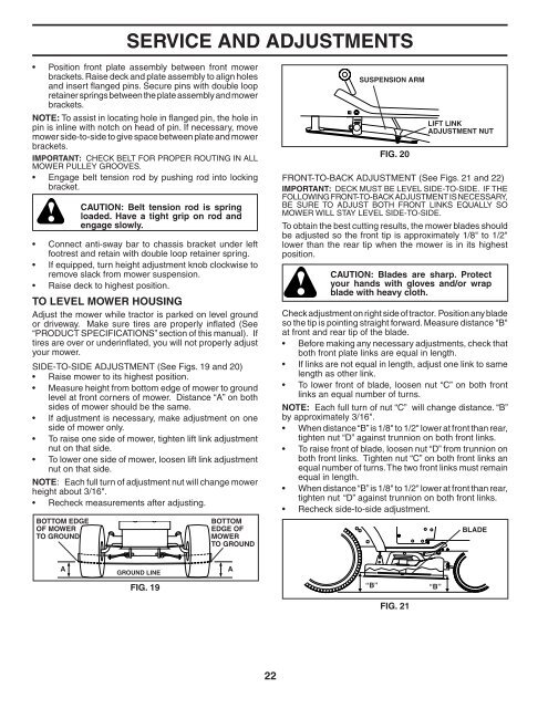
SIDE-TO-SIDE ADJUSTMENT (See Figs. 19 and 20)<br />
Raise mower to its highest position.<br />
Measure height from bottom edge of mower to ground<br />
level at front cor ners of mower. Distance “A” on both<br />
sides of mower should be the same.<br />
If adjustment is necessary, make adjustment on one<br />
side of mower only.<br />
To raise one side of mower, tighten lift link ad just ment<br />
nut on that side.<br />
To lower one side of mower, loosen lift link ad just ment<br />
nut on that side.<br />
NOTE: Each full turn of adjustment nut will change mower<br />
height about 3/16".<br />
Recheck measurements after ad just ing.<br />
GROUND LINE<br />
FIG. 19<br />
BOTT<strong>OM</strong><br />
EDGE OF<br />
MOWER<br />
TO GROUND<br />
A<br />
22<br />
SUSPENSION ARM<br />
“B”<br />
FIG. 20<br />
FIG. 21<br />
LIFT LINK<br />
AD JUST MENT NUT<br />
FRONT-TO-BACK ADJUSTMENT (See Figs. 21 and 22)<br />
IMPORTANT: DECK MUST BE LEVEL SIDE-TO-SIDE. IF THE<br />
FOLLOWING FRONT-TO-BACK AD JUST MENT IS NECESSARY,<br />
BE SURE TO ADJUST BOTH FRONT LINKS EQUALLY SO<br />
MOWER WILL STAY LEVEL SIDE-TO-SIDE.<br />
To obtain the best cutting re sults, the mower blades should<br />
be adjusted so the front tip is ap prox i mate ly 1/8" to 1/2"<br />
lower than the rear tip when the mower is in its highest<br />
position.<br />
CAUTION: Blades are sharp. Protect<br />
your hands with gloves and/or wrap<br />
blade with heavy cloth.<br />
Check adjustment on right side of trac tor. Position any blade<br />
so the tip is pointing straight forward. Measure distance "B"<br />
at front and rear tip of the blade.<br />
Before making any necessary ad just ments, check that<br />
both front plate links are equal in length.<br />
If links are not equal in length, adjust one link to same<br />
length as other link.<br />
To lower front of blade, loosen nut “C” on both front<br />
links an equal number of turns.<br />
NOTE: Each full turn of nut “C” will change distance. “B”<br />
by approximately 3/16".<br />
When distance “B” is 1/8" to 1/2" lower at front than rear,<br />
tighten nut “D” against trunnion on both front links.<br />
To raise front of blade, loosen nut “D” from trunnion on<br />
both front links. Tighten nut “C” on both front links an<br />
equal number of turns. The two front links must remain<br />
equal in length.<br />
When distance “B” is 1/8" to 1/2" lower at front than rear,<br />
tighten nut “D” against trunnion on both front links.<br />
Recheck side-to-side adjustment.<br />
“B”<br />
BLADE