INSTALLATION OPERATING & MAINTENANCE MANUAL - Lennox
INSTALLATION OPERATING & MAINTENANCE MANUAL - Lennox
INSTALLATION OPERATING & MAINTENANCE MANUAL - Lennox

You also want an ePaper? Increase the reach of your titles
YUMPU automatically turns print PDFs into web optimized ePapers that Google loves.
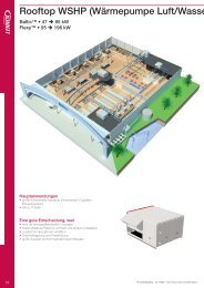
<strong>INSTALLATION</strong><br />
<strong>OPERATING</strong> &<br />
<strong>MAINTENANCE</strong> <strong>MANUAL</strong><br />
PROVISIONAL<br />
CLIMATIC 50 for<br />
FLEXY<br />
English<br />
May 2004
CONTENTS<br />
IOM <strong>MANUAL</strong><br />
The present manual applies to the following ROOFTOP versions :<br />
FCA 60 - FCA 70 - FCA 85 - FCA 100 - FCA 120 - FCA 140 - FCA 160 - FCA 190<br />
FCK 60 - FCK 70 - FCK 85 - FCK 100 - FCK 120 - FCK 140 - FCK 160 - FCK 190<br />
FHA 60 - FHA 70 - FHA 85 - FHA 100 - FHA 120 - FHA 140 - FHA 160 - FHA 190<br />
FHK 60 - FHK 70 - FHK 85 - FHK 100 - FHK 120 - FHK 140 - FHK 160 - FHK 190<br />
FDA 60 - FDA 70 - FDA 85 - FDA 100 - FDA 120 - FDA 140 - FDA 160 - FDA 190<br />
FDK 60 - FDK 70 - FDK 85 - FDK 100 - FDK 120 - FDK 140 - FDK 160 - FDK 190<br />
FGA 60 - FGA 70 - FGA 85 - FGA 100 - FGA 120 - FGA 140 - FGA 160 - FGA 190<br />
FGK 60 - FGK 70 - FGK 85 - FGK 100 - FGK 120 - FGK 140 - FGK 160 - FGK 190<br />
FXA 25 - FXA 30 - FXA 35 - FXA 40 - FXA 55 - FXA 70 - FXA 85 - FXA 100 - FXA 110 - FXA 140 - FXA 170<br />
FXK 25 - FXK 30 - FXK 35 - FXK 40 - FXK 55 - FXK 70 - FXK 85 - FXK 100 - FXK 110 - FXK 140 - FXK 170<br />
NOTES FOR UNIT FITTED WITH GAS BURNER:<br />
Ref. FLEXY-IOM-CL50-P-0504-E<br />
THE UNIT MUST BE INSTALLED IN ACCORDANCE WITH LOCAL SAFETY<br />
CODES AND REGULATIONS AND CAN ONLY BE USED IN WELL<br />
VENTILLATED AREA.<br />
PLEASE READ CAREFULLY THE MANUFACTURER'S INSTRUCTIONS<br />
BEFORE STARTING THIS UNIT.<br />
THIS <strong>MANUAL</strong> IS ONLY VALID FOR UNITS DISPLAYING THE FOLLOWING<br />
CODES: GB IR GR DA NO FI IS<br />
In case these symbols are not displayed on the unit, please refer to the<br />
technical documentation which will eventually detail any modifications required<br />
to the installation of the unit in a particular country.<br />
LENNOX have been providing environmental solutions since 1895, our range of Baltic TM rooftop continues to meet the standards<br />
that have made LENNOX a household name. Flexible design solutions to meet YOUR needs and uncompromising attention to<br />
detail. Engineered to last, simple to maintain and Quality that comes as standard. Information on local contacts at<br />
www.lennoxeurope.com.<br />
All the technical and technological information contained in this manual, including any drawing and technical descriptions<br />
provided by us, remain the property of <strong>Lennox</strong> and must not be utilised (except in operation of this product), reproduced, issued<br />
to or made available to third parties without the prior written agreement of <strong>Lennox</strong>.<br />
The technical information and specifications contained in this manual are for reference only. The manufacturer reserves<br />
the right to modify these without warning and without obligation to modify equipment already sold.<br />
IOM / ROOFTOP FLEXY Series -PROVISIONAL 0504 - E Page 1
control communication links<br />
CLIMATIC 50<br />
The new generation of microprocessor based control, CLIMATIC 50 is fitted to the FLEXY Rooftop range.<br />
It inherits 15 years of technology and field operating experience from its predecessors the CLIMATIC1 and CLIMATIC 2.<br />
LENNOX has found the latest hardware technology available on the market place and developed a software specifically<br />
designed for Rooftop applications, maximising the LENNOX Rooftop efficiency and performance.<br />
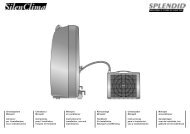
COMMUNICATION LINKS<br />
Master / Slave<br />
Rooftop can now be connected together (up to 12) via a double shielded pair of wire (0.75mm2 not supplied by <strong>Lennox</strong>) and<br />
use different running modes, as explained bellow, with no cost increase.<br />
Fig. 81<br />
Table 7<br />
Page 2 - IOM / ROOFTOP FLEXY Series -PROVISIONAL 0504 - E<br />
SET ROOM COOLING<br />
FAN POINT TEMP HEAT MODE<br />
1.Total master / slave MASTER MASTER MASTER N/A<br />
2. Master / slave temperature MASTER STAND ALONE MASTER N/A<br />
3 Master / slave average MASTER STAND ALONE AVERAGE N/A<br />
4 Master / slave heating / cooling STAND ALONE STAND ALONE STAND ALONE MASTER<br />
5 Back-up All units are stand alone one unit is waiting for a failure to start<br />
6 Rolling Back-up All units are stand alone, one unit is waiting for a failure to start.<br />
This back-up unit changes every Tuesday<br />
_ 1 : Master slave mode "total"<br />
The master gives the ventilation order, its set point and its<br />
room temperature/humidity to all other rooftops.<br />
_ 2 : Master slave mode "temperature"<br />
The master gives the ventilation order and its room<br />
temperature/humidity to all other rooftops, but they have<br />
their own set point.<br />
_ 3 : Master slave mode "average"<br />
The master gives the ventilation order and the room<br />
temperature/humidity used by all rooftop is the average of<br />
all rooftop. Each rooftop has its own set point.<br />
_ 4 : Master slave mode "cooling/heating"<br />
All rooftop are stand-alone but the slaves have to have the<br />
same running mode as the master (Cooling or heating).<br />
_ 5 : Back-up mode<br />
One rooftop is the back-up unit and will operate if any of the<br />
other rooftop has a failure.<br />
_ 6 : Rolling Back-up mode<br />
Same as above, except the "back-up" unit will be different<br />
each Tuesday. On top of that, the outside temperature/<br />
humidity given to all rooftop can either be the average of<br />
rooftop or be the external humidity/temperature of the<br />
master, making possible the use of a single "weather<br />
station" for the whole site.DS50 Comfort Display / DC50<br />
Service Display.
control communication links<br />
DS 50 : SERVICE DISPLAY / DC 50 : COMFORT DISPLAY<br />
Fig. 82<br />
CLIMALINK / CLIMALOOK<br />
Fig. 83<br />
IOM / ROOFTOP FLEXY Series -PROVISIONAL 0504 - E Page 3
control software features<br />
CLIMATIC 50 SOFTWARE FEATURES AND LOGIC<br />
CLIMATIC 50 provides flexibility and the ability to control<br />
multiple Rooftops on a single site.<br />
Enhanced with a 16 bit processor at 14Mhz and a 2<br />
Megabytes flash memory, CLIMATIC 50 has been<br />
designed to save energy and to extend the operational life of<br />
the FLEXY product range. It is able to control 50 fault<br />
signals and manage security algorithms generating various<br />
fault signals. In terms of comfort, CLIMATIC 50 provides<br />
an innovative PI control.<br />
CLIMATIC 50 offers incredible flexibility. For example,<br />
advanced users can go in the heart of the regulation and<br />
adjust the reactivity of the PI algorithm or set the supply<br />
temperature limits .<br />
As a standard feature, CLIMATIC50 provides 4 scheduling<br />
time zones per day on 7 days. On each of the 4 time zones,<br />
heating set point, cooling set point, minimum fresh air,<br />
humidity set point high and up, and even the different<br />
authorisations for cooling and heating can be adjusted.<br />
CLIMATIC 50 provides a choice of different remote<br />
displays depending on customer requirement and application<br />
of the system. As a standard feature, it is possible to set<br />
alarms (adjustable value low and high) on room temperature<br />
and humidity.<br />
CONTROL SOFTWARE LOGIC<br />
With the CLIMATIC 50 <strong>Lennox</strong> is going away from the<br />
traditional step control<br />
Capacity factor<br />
It is used to determine the exact capacity required at any<br />
time in order to react quicker and more accurately to any<br />
change in demand.<br />
The capacity factor is a percentage of the total cooling or<br />
heating capacity.<br />
Example:<br />
On a three circuit rooftop unit with two compressors running<br />
out of three has a capacity factor of 66%<br />
In the same way, a three circuit rooftop with a modulating<br />
electric heater running at 20% of its full capacity has a CF:<br />
CF = 25%+25%+25%+5% = 80%<br />
The Capacity factor will increase, decrease, or freeze<br />
depending on the temperature difference between the set<br />
point and the room temperature but also on the way this<br />
room temperature is changing:<br />
Page 4 - IOM / ROOFTOP FLEXY Series -PROVISIONAL 0504 - E<br />
Δ<br />
Rom Temp / Set Point<br />
Example:<br />
Reactivity.<br />
CAPACITY<br />
FACTOR IS<br />
FROZEN<br />
CAPACITY FACTOR<br />
IS DECREASED<br />
(REDUCE CAPACITY)<br />
CAPACITY FACTOR<br />
IS INCREASED<br />
(ADD CAPACITY)<br />
CAPACITY<br />
FACTOR IS<br />
FROZEN<br />
The room set point is 25°C with a 3 compressor unit.<br />
Delta vs<br />
room set Room Cap. COMP COMP COMP<br />
point Temp. factor 1 2 3<br />
+0 Increasing 0% OFF OFF OFF<br />
+1 Increasing 35% ON OFF OFF<br />
+2 Increasing 70% ON ON OFF<br />
+3 Increasing 100% ON ON ON<br />
+2 Decreasing 100% ON ON ON<br />
+1 Decreasing 100% ON ON ON<br />
0 Decreasing 100% ON ON ON<br />
-1 Decreasing 60% ON ON OFF<br />
0 Increasing 60% ON ON OFF<br />
The reactivity determines how fast the capacity factor should<br />
vary.<br />
It is given in: Percentage of capacity / >Degree °C ( Room<br />
Temp. VS Set Point) / minute<br />
Example :<br />
If the reactivity is set to 3 % / °C / min<br />
Then:<br />
Capacity factor can go from 0 to 30% in 10 minutes if<br />
Room Temp. VS Set Point is 1°C<br />
Or capacity factor will go from 0 to 60 % in 4 minutes if<br />
Room Temp. VS Set Point is 5°C<br />
Fig. 84<br />
Room Temp / Decreasing Room Temp / Increasing<br />
Table 8<br />
The reactivity can be adjusted with the CLIMATIC 50 The<br />
larger the reactivity the faster the rooftop will react to a<br />
change.<br />
The next table shows the effect of a change of the reactivity<br />
on the capacity factor: This shows that by increasing the<br />
reactivity, the unit reaches the set point quicker but the<br />
energy consumption (capacity factor) is larger.
control software features<br />
REACTIVITY : 3<br />
DELTA +5 15% 75% 100%<br />
DELTA +3 9% 45% 90%<br />
DELTA +1 1% 15% 30%<br />
REACTIVITY : 6<br />
OTHER FEATURES<br />
Dynamic Set Point<br />
This feature allows the set point to change according to the<br />
outside temperature.<br />
Example:<br />
If the set point is 25°C<br />
And the dynamic set point is set to 6°C<br />
Then, when the outdoor temperature reaches: 31°C (25°C +<br />
6°C) the set point will follow the outdoor temperature with a<br />
6°C temperature difference.<br />
Set<br />
Point<br />
Dynamic Set point : 6°C<br />
Outdoor Temperature<br />
If you do not want to use this feature, set the dynamic set<br />
point to 99<br />
Time Zones and scheduling<br />
1MIN 5MIN 10MIN<br />
DELTA +5 30% 100% 100%<br />
DELTA +3 18% 90% 100%<br />
DELTA +1 2% 30% 60%<br />
Table 9<br />
Table 10<br />
1MIN 5MIN 10MIN<br />
Fig.85<br />
With the Climatic50 the scheduling has been completely<br />
reviewed:<br />
The first day of the week is Monday.<br />
Automatic switch from winter time to summer time.<br />
Unoccupied mode from one to seven days<br />
Three occupied and one unoccupied zone per day<br />
For each zone a series of set points and feature can be<br />
adjusted or selected, depending on the type of display which<br />
is being used.<br />
LIST OF SET POINTS CONFORT SERVICE<br />
PER ZONE DISPLAY DISPLAY<br />
AMBIANT TEMPERATURE<br />
Average set point<br />
Yes Yes<br />
Dynamic Set Point Yes Yes<br />
Cooling Set Point 0 Yes<br />
Heating Set point 0 Yes<br />
Heating Priority 0 Yes<br />
FRESH AIR REHEAT activated 0 Yes<br />
Heating priority<br />
HUMIDITY<br />
0 Yes<br />
Dehumidification 0 Yes<br />
Humidification<br />
AUTHORIZATION<br />
0 Yes<br />
Free Cooling 0 Yes<br />
Fresh Air by CO2 0 Yes<br />
Mechanical cooling 0 Yes<br />
Mechanical heating 0 Yes<br />
Auxiliary heating<br />
OTHER<br />
0 Yes<br />
Fan Mode :On / Off / Auto 0 Yes<br />
Minimum fresh air (%)<br />
SCHEDULING<br />
Yes Yes<br />
Beginning of the zone for each day Yes Yes<br />
Table 12<br />
Each zone is determined by its starting time.<br />
Forced modes<br />
8h00 12h00 14h00 20h00<br />
3 hours Override<br />
A three hours override period can be forced on the<br />
CLIMATIC TM 50:<br />
With this feature, a new room temperature set point and<br />
fresh air requirement can be imposed for a three hour<br />
period; It will then revert to the original setting at the end of<br />
the override period or earlier by switching off the override on<br />
the controller display.<br />
Forced unoccupied zone.<br />
The unoccupied zone settings can be forced for a period of<br />
up to seven days. It will then revert to the original settings at<br />
the end of the defined period or earlier by switching off the<br />
forced unoccupied mode on the controller display.<br />
Heating priorities<br />
It is possible to set heating priorities depending on the<br />
outdoor temperature.<br />
Table 11<br />
Monday Unoc. ZA ZB ZC Unoc.<br />
Tuesday<br />
Wed.<br />
Thursday<br />
Friday<br />
Saturday<br />
Sunday<br />
Example:<br />
It could be decided based on energy costs, that on a dual<br />
fuel unit, it should run in heat pump mode when the<br />
temperature is above 0°C and switch to gas burner below<br />
that point.<br />
IOM / ROOFTOP FLEXY Series -PROVISIONAL 0504 - E Page 5
control software features<br />
Staggered start<br />
After a power cut, the units can be made to restart one after<br />
the other to prevent any current surge.<br />
There is no need for a link between the units, they just have<br />
to be given an address during commissioning and they will<br />
restart 10 seconds x their "address number" after the power<br />
is switched back on.<br />
Example:<br />
If a unit is given the address N°3 it will be switched-on 30<br />
seconds (3 x 10sec) after the power is switched back on.<br />
Fresh air adjustment and calibration on Economiser<br />
The actual fresh air volume brought into the system is not<br />
always proportional to the percentage of opening of the<br />
fresh air damper. That is particularly true when the return air<br />
duct system has been sized to produce excessive pressure<br />
drop.<br />
This often results in bringing into the system an excessive<br />
amount of fresh air, hence increasing the running cost of the<br />
system.<br />
Actual<br />
Fresh<br />
Air<br />
Actual<br />
Required<br />
Damper position<br />
The control of fresh air is now achieved through the use of<br />
three temperature sensors: One in the supply air flow, one in<br />
the return air and one for the outdoor temperature.<br />
Using these three sensors, the Climatic50 will calculate and<br />
memorise the exact percentage of fresh air for each position<br />
of the damper.<br />
T supply air = T return air x % Return air + T fresh air x % fresh air<br />
Fig.86<br />
The calibration sequence will take place periodically when<br />
all cooling or heating inputs are off.<br />
Page 6 - IOM / ROOFTOP FLEXY Series -PROVISIONAL 0504 - E<br />
Dynamic Defrost<br />
This new feature patented under INPI 91.033.063 allows the<br />
unit to start the defrost cycle only when required.<br />
This is achieved through the measurement of the<br />
temperature difference between the coil and the outdoor.<br />
The defrost will be initiated shortly after the Climatic50 has<br />
located the largest gradient in the curve.<br />
The defrost cycle ends when one of these two condition is<br />
completed whichever comes first:<br />
+ Three defrost cycles max.<br />
+ 4 minutes.<br />
Temp.<br />
difference<br />
between<br />
coil and<br />
outdoor<br />
Coil<br />
Clean<br />
Defrost cycle start<br />
Highest gradient<br />
Coil<br />
Freezing<br />
Alternate defrost (Optional size on 85-100)<br />
Time<br />
Fig.87<br />
Coil<br />
Frozen<br />
All dual circuits Flexy units have "Alternate Defrost" as a<br />
standard feature.<br />
When one circuit is going through a defrost cycle the<br />
second circuit is running in heat pump mode. This reduces<br />
the need for costly electric heater to maintain the supply air<br />
temperature to an acceptable level of comfort during the<br />
defrost cycles.<br />
Fig.88
control interface dc50<br />
CONTROL INTERFACES AND DISPLAYS<br />
DC50 COMFORT DISPLAY<br />
This is a remote controller for non-technical customer. This<br />
display give information such as running mode status of the<br />
fan, set point, % of fresh air and outside air temperature.<br />
It can be used to set or change the scheduling of the<br />
different time zones, the temperature set point, and the % of<br />
fresh air for each zone. It also has the capacity to set a 3<br />
hours override and to force the unoccupied mode for up to 7<br />
days. It displays the real time clock and different faults<br />
signals.<br />
Keys<br />
Set time<br />
Main Screen<br />
Actual<br />
Fresh Air<br />
Room Temp<br />
Outdoor air<br />
temperature<br />
Time zone<br />
settings<br />
24.2°C ON<br />
FA:20% DynFan:Auto<br />
Out:40.0°C Z:A Cool<br />
Back to main<br />
Screen or<br />
Cancel<br />
"Override"<br />
Dynamic<br />
Set Point<br />
Activated<br />
Fan<br />
status<br />
24.2°C ON<br />
FA:20% DynFan:Auto<br />
Out:40.0°C Z:A Cool<br />
Current<br />
Time zone<br />
Z:A<br />
Z:B<br />
Z:C<br />
Uno<br />
Ove<br />
BMS<br />
Increase a<br />
value or go to<br />
"Override<br />
menu"<br />
Change<br />
field or<br />
validate<br />
Decrease a<br />
value or go to<br />
"Override<br />
menu"<br />
Fan auto<br />
means that<br />
fan will stop if<br />
there is no<br />
demand for<br />
cooling or<br />
heating.<br />
Unit operating Mode<br />
:<br />
Cool or Heat<br />
Override 3 hours :<br />
From main screen press any of the two arrow keys as<br />
shown bellow:<br />
Main screen :<br />
Override menu :<br />
Override 3 hours<br />
Room SP : 24.0°C<br />
Mini FA : 20%<br />
Unoc :<br />
Valid go main<br />
screen<br />
24.2°C ON<br />
FA:20% DynFan:Auto<br />
Out:40.0°C Z:A Cool<br />
Set unoccupied Period<br />
Room SP : 24.0°C<br />
Mini FA : 20%<br />
Uno :M T W T F S S<br />
Increase<br />
Valid /<br />
Go<br />
next line<br />
Decrease<br />
It will revert back to main screen after 15 seconds, if no activity<br />
Forced Unoccupied zone :<br />
Select "unoc" in the override menu and validate<br />
UP to 7 days unoccupied period (starting from current day).<br />
Clock Menu :<br />
+1 day unoccupied<br />
Valid<br />
-1 day unoccupied<br />
From main screen press the clock key, the following menu<br />
appears:<br />
Back to Main<br />
12 h 24<br />
Thursday March 27<br />
Increase<br />
Valid<br />
Decrease<br />
IOM / ROOFTOP FLEXY Series -PROVISIONAL 0504 - E Page 7
control interface dc50<br />
"Time Zone" Menu<br />
From main screen press the "Prg" key, the following menu<br />
appears:<br />
Change<br />
Time zone<br />
Change<br />
day<br />
AMBER<br />
AMBER<br />
Schedule<br />
Time zone : A<br />
ROOM SP : 24.0°C<br />
Min FA : 20%<br />
Back to main<br />
Day : Monday<br />
Start<br />
ZA:8h00 Z.B.12h00<br />
ZC:22h00 uno:22h00<br />
Back to main<br />
RED<br />
24.2°C ON<br />
Alarm : Filter<br />
Clean filter<br />
RED<br />
24.2°C OFF<br />
Alarm : MAJOR<br />
call for maintenance<br />
Increase<br />
Decrease<br />
It will reverts back to main screen after 15 seconds if no<br />
activity.<br />
"Scheduling" Menu<br />
Valid /<br />
Go<br />
next line<br />
The scheduling menu can be accessed from the "time zone"<br />
menu by pressing "Prg" again<br />
Alarm screen<br />
Increase<br />
Valid /<br />
Go<br />
next line<br />
Decrease<br />
Filter Alarm: All keys are locked, the only way to escape this<br />
screen is to clean the filter<br />
Major Alarm<br />
Alarms<br />
History<br />
Page 8 - IOM / ROOFTOP FLEXY Series -PROVISIONAL 0504 - E<br />
Alarm History Menu<br />
AMBER<br />
You can scroll down this menu using the arrow keys and<br />
select one of the alarm message by pressing the return<br />
key.<br />
Alarm details<br />
This menu allows you to view details on the selected fault<br />
as shown below:<br />
RED<br />
AMBER<br />
RED<br />
Alarm 02<br />
01-03/03.12h10*127<br />
02 03/03.12h05*127<br />
03-27/02.12h03 = 127<br />
Alarm 00<br />
03/03 12h05*125<br />
Compressor 2<br />
High Pres./Elec.Power<br />
Switching ON and OFF the unit<br />
Pressing the return key on the main screen will display the<br />
following message:<br />
WARNING : Switching Off the unit disable all safety<br />
Protections<br />
Do you want to<br />
switch off the unit ?<br />
NO<br />
Move up and down to display "YES" then pressing the<br />
return key again will switch off the unit.<br />
24.2°C OFF<br />
Alarms<br />
Detail<br />
It can then be switched back ON by pressing the return key<br />
once more.
control interface dS50<br />
DS50 SERVICE DISPLAY<br />
This new service display controller is a plug and play<br />
feature but it can also be remotely installed.<br />
Plugging the DS50 will freeze a DC50<br />
Keys<br />
Change<br />
Time zone<br />
Start<br />
Select item<br />
Capital letter<br />
Short cut to<br />
alarm menu<br />
Go back to<br />
screen (1)<br />
Start up screen or Screen(1)<br />
Language or<br />
ENGLISH<br />
RT 050.001<br />
BIOS. 0000 Boot 0000<br />
LENNOX SERVICE TOOL<br />
Press Prg to start<br />
Screen (2) language selection<br />
Language or<br />
ENGLISH<br />
RT 050.001<br />
BIOS. 0000 Boot 0000<br />
Rooftop Number<br />
(0000)01 ZoneA<br />
1-ALARM 12h44<br />
2-Data Tuesday<br />
3-Setting April 03<br />
Current<br />
Time<br />
zone<br />
Move up in a<br />
menu or<br />
increase a<br />
value<br />
Enter<br />
Valid<br />
Select<br />
Move down in<br />
a menu or<br />
decrease<br />
value<br />
Five languages are available in addition to English. The<br />
required language must be specified at the time of order.<br />
In this menu the specified language can be selected using<br />
the up and down keys. The "prg" key validates the choice<br />
and start the controller.<br />
Main menu (0000)<br />
Moving down the menus<br />
Pressing the arrow keys allows you to move up and down the<br />
menu tree. The selected item changes to CAPITAL letter. It<br />
can then be selected by pressing the "return" or "select" key.<br />
Sub-menu Data (2000)<br />
Menu reference<br />
3 x<br />
(0000)01 ZoneA<br />
1-ALARM 12h44<br />
2-Data Tuesday<br />
3-Setting April 03<br />
(0000)01 ZoneA<br />
1-ALARM 12h44<br />
2-Data Tuesday<br />
3-Setting April 03<br />
(2000)01<br />
1-GENERAL<br />
2-Control<br />
3 Information<br />
(2110)01<br />
1-OUTSIDE 40°C<br />
2-Room 24.5°C<br />
3-Supply 10.0°C<br />
Down<br />
SELECT<br />
Indicates other<br />
menus below<br />
If the menu GENERAL is selected, the controller then<br />
displays a second level sub-menu.<br />
By selecting the item TEMPERATURE and pressing return, a third<br />
(2100)01<br />
1-TEMPERATURE<br />
2-Humidity<br />
3-Other<br />
level page is displayed as shown bellow:<br />
IOM / ROOFTOP FLEXY Series -PROVISIONAL 0504 - E Page 9
control interface dS50<br />
Pressing "ESC" at any time sends you back one level up<br />
the menu tree. In the example shown above "ESC" must be<br />
pressed 3 times to go back to the main menu (0000)<br />
Pressing "ESC" will invalidate any changes made to a<br />
value in a setting page.<br />
Alarms<br />
RED<br />
RESET<br />
RED<br />
(0000)01 ZoneA<br />
1-ALARM 12h44<br />
2-Data Tuesday<br />
3-Setting April 03<br />
Select the alarm menu using the arrow keys and press<br />
return.<br />
The faults history is then displayed in the page (1000):<br />
(1000) 01 Alarm 02<br />
01-03/03.12h10*127<br />
02 03/03.12h05*125<br />
03-27/02.12h03 = 125<br />
Selected Alarm Alarm Date<br />
and Time<br />
(1000) 01 Alarm 00<br />
01-03/03.12h10 = 127<br />
02 03/03.12h05 = 125<br />
03-27/02.12h03 = 125<br />
Active * or<br />
Inactive =<br />
Number of<br />
active Alarm<br />
Pressing the "ALARM" key resets all the alarms<br />
The number of active alarms goes to 0, no active alarm<br />
shown in the menu, the "bell" key is switched off.<br />
SELECT<br />
Alarm<br />
code<br />
Pressing the "return" key will display details of the selected<br />
alarm<br />
(1100) 01 Alarm 00<br />
03/03.12h05 = 125<br />
Compressor 2<br />
High pres/Elec.power<br />
Page 10 - IOM / ROOFTOP FLEXY Series -PROVISIONAL 0504 - E<br />
Clock settings<br />
The clock setting menu can be accessed from the main<br />
menu by selecting the menu "SETTING" and then<br />
navigating down through the sub-menus until page (3120).<br />
(3120) 01<br />
1-HOUR 12h<br />
2-Minute 44mn<br />
3-Day 4<br />
Selecting the HOUR for displays the page 3121 shown<br />
bellow:<br />
Min Setting<br />
Up one<br />
level<br />
Current Setting<br />
(3121) 01<br />
min:00<br />
HOUR STD:<br />
14h max:23<br />
Zone Settings<br />
From Main menu (0000) navigate down to sub-menu<br />
"SETTINGS", zone settings (3310).<br />
"prg" changes<br />
the time zone<br />
Factory<br />
Setting<br />
(3310) 01 Zone.A<br />
1-ROOM SET : 24.0°C<br />
2-Min % FA : 20 %<br />
(3121) 01 Zone.A<br />
min:8.0<br />
Room set std :20.0<br />
21.0°C max:35.0<br />
Validate and<br />
Back One level<br />
Max<br />
Setting<br />
Selected Time<br />
zone<br />
In this particular page, pressing the "prg" key, changes the<br />
time zone. If "ROOM SET" is selected, this displays the<br />
room set point for the specific time zone shown in the top<br />
corner.<br />
Pressing the "prg" validates any changes made, and move<br />
to the next time zone. "ESC" does not validate the changes<br />
and move back one step in the menu tree.
control interfaces ds50 menu tree<br />
Table 13<br />
Main Screen Code Description Code Description Code Description Code UNIT Min Factory Max<br />
1-Alarm 1000 1-(date).(time) 1100<br />
2-(date).(time) 1200<br />
3-(date).(time) 1300<br />
2-Data 2000 1-General 2100 1-Temperature 2110 Outside °C<br />
Room °C<br />
Supply °C<br />
Return °C<br />
2-Humidity 2120 Outside %.<br />
Room %.<br />
Outside g/kg<br />
Room g/kg<br />
3-Other 2130 Air Pres. Pa<br />
CO2 ppm<br />
Sw On/Off On/Off<br />
Sw Reset On/Off<br />
Sw Unoc. On/Off<br />
4-Customized 2140 Temp. 1 °C<br />
Temp. 2 °C<br />
Temp. 3 °C<br />
Temp. 4 °C<br />
Humi. 1 %.<br />
Humi. 2 %.<br />
Humi. 3 %.<br />
Humi. 4 %.<br />
5-Customized 2150 Switch 1 On/Off<br />
Switch 2 On/Off<br />
Switch 3 On/Off<br />
Switch 4 On/Off<br />
Switch 5 On/Off<br />
Switch 6 On/Off<br />
6-Customized 2160 Relay 1 On/Off<br />
Relay 2 On/Off<br />
Relay 3 On/Off<br />
Relay 4 On/Off<br />
Relay 5 On/Off<br />
2-Control 2200 1-Room 2210 Sp Cool °C<br />
Sp Heat °C<br />
Capa Cool %<br />
Capa Heat %<br />
Sw Dis.Cool On/Off<br />
Sw Dis.Heat On/Off<br />
2-Reheat 2220 Set Point °C<br />
Capacity %<br />
3-Humidity 2230 Sp Dehu %<br />
Sp Humi %<br />
Capa Dehu %<br />
Capa Humi %<br />
4-TCB 2240Sw G On/Off<br />
Sw Y1 On/Off<br />
Sw Y2 On/Off<br />
Sw W1 On/Off<br />
Sw W2 On/Off<br />
Sw B On/Off<br />
IOM / ROOFTOP FLEXY Series -PROVISIONAL 0504 - E Page 11
Main Screen Code Description Code Description Code Description Code UNIT Min Factory Max<br />
3-Fan 2300 1-Ventilation 2310 Config. List<br />
State List<br />
Sw State On/Off<br />
Fire/Smoke On/Off<br />
Relay On/Off<br />
Low Speed On/Off<br />
Sw Speed On/Off<br />
2-Extraction 2320 State List<br />
Relay On/Off<br />
3-Condenser 1 2330 Config. List<br />
State List<br />
Sw State On/Off<br />
Relay On/Off<br />
4-Condenser 2 2340 Config. List<br />
State List<br />
Sw State On/Off<br />
Relay On/Off<br />
5-Condenser 3 2350 Config. List<br />
State List<br />
Sw State On/Off<br />
Relay On/Off<br />
6-Condenser 4 2360 Config. List<br />
State List<br />
Sw State On/Off<br />
Relay On/Off<br />
4-Fresh Air 2410 Config. List<br />
State List<br />
Opening %<br />
5-Compressor 2500 1-Compressor 1 2510 Config. List<br />
State List<br />
Defrost T °C<br />
Sw State On/Off<br />
Sw Low P. On/Off<br />
Relay On/Off<br />
H.Pump On/Off<br />
Sw Disable On/Off<br />
2-Compressor 2 2520 Config. List<br />
State List<br />
Defrost T. °C<br />
Sw State On/Off<br />
Sw Low P. On/Off<br />
Relay On/Off<br />
H.Pump On/Off<br />
Sw Disable On/Off<br />
3-Compressor 3 2530 Config. List<br />
State List<br />
Defrost T. °C<br />
Sw State On/Off<br />
Sw Low P. On/Off<br />
Relay On/Off<br />
H.Pump On/Off<br />
Sw Disable On/Off<br />
4-Compressor 4 2540 Config. List<br />
State List<br />
Defrost T. °C<br />
Sw State On/Off<br />
Sw Low P. On/Off<br />
Relay On/Off<br />
H.Pump On/Off<br />
Sw Disable On/Off<br />
Page 12 - IOM / ROOFTOP FLEXY Series -PROVISIONAL 0504 - E
control interfaces ds50 menu tree<br />
Main Screen Code Description Code Description Code Description CodeUNIT Min Factory Max<br />
5-Other 2550 Low Amb. On/Off<br />
W/Cond.1 °C<br />
W/Cond.2 °C<br />
6-Aux. Heater 2600 1-Gas 2610 Config. List<br />
State List<br />
Sw State 1 On/Off<br />
Sw State 2 On/Off<br />
Relay 1 On/Off<br />
Relay 2 On/Off<br />
High On/Off<br />
Modulat. %<br />
Sw Disable On/Off<br />
2-Elec. H. 2620 Config. List<br />
State List<br />
Sw State 1 On/Off<br />
Sw State 2 On/Off<br />
Relay 1 On/Off<br />
Relay 2 On/Off<br />
Modulat. %<br />
Sw Disable On/Off<br />
3-Hot W/Coil 2630 Config. List<br />
State List<br />
Opening %<br />
Sw Freeze On/Off<br />
Sw Disable On/Off<br />
4-Pump 2640 Config. List<br />
State List<br />
Sw State On/Off<br />
Relay On/Off<br />
7-Humidif. 2710 Config. List<br />
State List<br />
Sw State On/Off<br />
Modulat. %<br />
8-Com. 2800 1-Outside 2810 Value °C<br />
Sensor °C<br />
Link °C<br />
BMS °C<br />
Value %.<br />
Sensor %.<br />
Link %.<br />
BMS %.<br />
2-Room 2820 Value °C<br />
Sensor °C<br />
Link °C<br />
BMS °C<br />
Value %.<br />
Sensor %.<br />
Link %.<br />
BMS %.<br />
IOM / ROOFTOP FLEXY Series -PROVISIONAL 0504 - E Page 13
description<br />
Main Screen Code Description Code Description Code Description Code UNIT Min Factory Max<br />
*[On / Off] Unit<br />
*[Reset] Discharges the safety measures of the unit<br />
*[Override] Cancel any override action set with the DC50<br />
*[TEST] Test set point "LENNOX"<br />
*[Clock] Clock setting "Hour"<br />
*[Clock] Clock setting "Minute"<br />
*[Clock] Clock setting "Day"<br />
*[Clock] Clock setting "Month"<br />
*[Clock] Clock setting "Year"<br />
*[Zone Setting] Starting time "Hour" for "Unocupied" zone<br />
*[Zone Setting] Starting time "Minutes" for "Unocupied" zone<br />
*[Zone Setting] Starting time "Hour" for "Zone A"<br />
*[Zone Setting] Starting time "Minutes" for "Zone A"<br />
*[Zone Setting] Starting time "Hour" for "Zone B"<br />
*[Zone Setting] Starting time "Minutes" for "Zone B"<br />
*[Zone Setting] Starting time "Hour" for "Zone C"<br />
*[Zone Setting] Starting time "Minutes" for "Zone C"<br />
*[Anticipation Function] bottom of the slope in °C. Limit of<br />
activation of the function. This allows an anticipated startup in<br />
the morning depending on the outdoor temperature. Only for<br />
the "Zone-A"<br />
*[Anticipation Function] Slope in "Minutes of anticipation per<br />
degrees".This allows an anticipated startup in the morning<br />
depending on the outdoor temperature.Only for the "Zone-A"<br />
*[Room SP] Required room temperature set point in °C.<br />
Middle of the dead zone.<br />
[Room SP] Required room minimum fresh air rate in %<br />
Middle of the dead zone.<br />
*[Room SP] Required value for the Dynamic Set Point. Allows<br />
the room set point to change according to outdoor<br />
temperature<br />
*[Room SP] Required maximum room temperature in °C.<br />
Cooling set point<br />
*[Room SP] Required minimum room temperature in °C.<br />
Heating set point<br />
*[OFF] Heat Pump and then Heater [ON] Heater and then<br />
Heat Pump<br />
*[F-Air Reheat] Activate reheating of the fresh air in the dead<br />
zone to maintain supply temperature.<br />
*[F-Air Reheat] Prioritise the heating mode for fresh air<br />
reheat. [OFF] Heat Pump and then Heater [ON] Heater and<br />
then Heat Pump<br />
*[Humidity] Desired Maximum relative humidity in Room (in<br />
%). – Dehumidification set point.<br />
*[Humidity] Desired Minimum relative humidity in Room (in<br />
%). – Humidification set point.<br />
3-Setting 3000 1-General 3100 1-Order 3110 1-On/Off 3111 On/Off ~ Off ~<br />
2-Reset Al. 3112 On/Off ~ Off ~<br />
3-Resume 3113 On/Off ~ Off ~<br />
4-Test 3114 List 0 0 2<br />
2-Clock 3120 1-Hour 3121 h 0 ~ 23<br />
2-Minute 3122 m 0 ~ 59<br />
3-Day 3123 ~ 1 ~ 31<br />
4-Month 3124 ~ 1 ~ 12<br />
5-Year 3125 ~ 2 ~ 99<br />
2-Schedule 3200 1-Time 3210 1-Start Uno 3211 h 0 22 23<br />
2-Start Uno 3212 m 0 0 59<br />
3-Start z.A 3213 h 0 6 23<br />
4-Start z.A 3214 m 0 0 59<br />
5-Start z.B 3215 h 0 22 23<br />
6-Start z.B 3216 m 0 0 59<br />
7-Start z.C 3217 h 0 22 23<br />
8-Start z.C 3218 m 0 0 59<br />
2-Anticipation 3220 1-Foot 3221 °C -10 10 20<br />
ALL CODES SHOWING (1) CAN BE ADJUSTED FOR EACH TIME ZONE<br />
Page 14 - IOM / ROOFTOP FLEXY Series -PROVISIONAL 0504 - E<br />
2-Gradient 3222 ~ 0 0 100<br />
3-Control 3300 1-Customer 3310 1-Sp Room 3311 (1) °C 8 20 35<br />
2-Mini.Air 3312 (1) % 0 20 100<br />
2-Room 3320 1-Sp Dyna 3321 (1) °C 0 99,9 99,9<br />
2-Sp Cool 3322 (1) °C 8 21 35<br />
3-Sp Heat 3323 (1) °C 8 19 35<br />
4-Swap Heater 3324 (1) On/Off ~ Off ~<br />
3-Reheat 3330 1-Activation 3331 (1) On/Off ~ Off ~<br />
2-Swap Heater 3332 (1) On/Off ~ Off ~<br />
3340 1-Sp Dehu 3341 (1) % 0 100 100<br />
2-Sp Humi 3342 (1) % 0 0 100
control interfaces ds50 menu tree<br />
description<br />
Main Screen Code Description Code Description Code Description Code UNIT Min Factory Max<br />
*[Enable] Stopping and running of the Fan Blower.[OFF] the<br />
blower is stopped, [ON] the blower is running.<br />
*[Enable] Stopping and running of the fan in the "Control<br />
Dead Zone". [OFF] the blower is stopped, [ON] the blower is<br />
running.<br />
*[Enable] Run eco: [ON] the Economiser is running, [OFF]<br />
the Economiser if stopped.<br />
*[Enable] Run CO2 Sensor: [ON] Switch-on the CO2 on a<br />
Zone, [OFF]Stop the CO2 sensor on a zone.<br />
*[Enable] [OFF] Force the unloading of compressors in<br />
cooling mode.<br />
*[Enable] [OFF] Force the unloading of compressors in<br />
heating mode.<br />
*[Enable] [OFF] Force the unloading of heating module<br />
(electric, gas or heat water coil)<br />
*[Enable] [OFF] Force the unloading of humidity control.<br />
*[Enable] Force the noise reduction mode. [ON] 50% of the<br />
compressors are unloaded in "Unocupied" zone<br />
*[Capacity Factor] Reactivity : Refer to "Climatic features" in<br />
*IOM for details<br />
*[Capacity Factor] Reactivity: Refer to "Climatic features" in<br />
*IOM for details<br />
*[Safety Limit] Room temperature "Low Limit" in °C Threshold<br />
of activation of an alarm<br />
*[Safety Limit] Room temperature "High Limit" in °C<br />
Threshold of activation of an alarm<br />
*[Safety Limit] Supply temperature low Limit (in °c) -<br />
Threshold of activation of the 1° level of security: Reduce the<br />
"Capacity Factor" by one stage of compressor and switch to<br />
minimum Fresh Air,<br />
*[Safety Limit] Supply temperature low Limit (in °c) -<br />
Threshold of activation of the 2° level of security: Reduce the<br />
"Capacity Factor" to zero and switch to 0% Fresh Air,open the<br />
HWC valve.<br />
*[Safety Limit] Supply temperature low Limit (in °c) -<br />
Threshold of activation of the 3° level of security. - Alarm<br />
threshold, the unit is switched off.<br />
*[Safety Limit] Supply temperature high Limit (in °c) -<br />
Threshold of activation of the 1° level of security: reduce the<br />
capacity factor by one stage of compressor. Close the HWC<br />
valve.<br />
*[Safety Limit] Supply temperature high Limit (in °c) -<br />
Threshold of activation of the 2° level of security: Alarm<br />
threshold: Reduce the capacity factor to 0<br />
*[Safety Limit] Room relative humidity low Limit (in %) -<br />
Threshold of activation of the alarm<br />
*[Safety Limit] Room humidity high Limit (in %) - Threshold of<br />
activation of the alarm<br />
*[Safety Limit] Airflow Detection Threshold of pressure<br />
difference in Pa indicating Low Airflow Rate. If the pressure<br />
difference across the filter is lower than this threshold the<br />
safety is activated.<br />
5-Enable 3350 1-Fan On/Off 3351 (1) On/Off ~ On ~<br />
2-Fan Dead 3352 (1) On/Off ~ On ~<br />
3-F.Air 3353 (1) On/Off ~ On ~<br />
4-CO2 3354 (1) On/Off ~ On ~<br />
5-Comp.Cool. 3355 (1) On/Off ~ On ~<br />
6-Comp.Heat. 3356 (1) On/Off ~ On ~<br />
7-AuxHeat 3357 (1) On/Off ~ On ~<br />
8-Humidif. 3358 (1) On/Off ~ On ~<br />
9-Low Noise 3359 (1) On/Off ~ Off ~<br />
6-Capacity 3360 1-Room 3361 ~ 1 4 100<br />
ALL CODES SHOWING (1) CAN BE ADJUSTED FOR EACH TIME ZONE<br />
2-Reheat 3362 ~ 1 4 100<br />
7-Safety 3370 1-Room Low 3371 °C 5 5 20<br />
2-Room High 3372 °C 20 40 40<br />
3-Sup.Lo.1 3373 °C 9 or 5 10 or 8 19<br />
4-Sup.Lo.2 3374 °C 7 or 3 8 or 6 17<br />
5-Sup.Lo.3 3375 °C 5 or 1 6 or 2 15<br />
6-Sup.Hi.1 3376 °C 20 40 70<br />
7-Sup.Hi.2 3377 °C 20 60 70<br />
8-Room Low 3378 % 0 0 100<br />
9-Room High 3379 % 0 100 100<br />
4-Ventilation 3410 1-Air Flow 3411 Pa 0 25 1000<br />
IOM / ROOFTOP FLEXY Series -PROVISIONAL 0504 - E Page 15
description<br />
Main Screen Code Description Code Description Code Description Code UNIT Min Factory Max<br />
*[Safety Limit] Airflow Detection Threshold of pressure<br />
difference in Pa indicating Low Airflow Rate. If the pressure<br />
difference across the filter is lower than this threshold the<br />
safety is activated.<br />
*[Safety Limit] Missing Filters. Threshold of pressure<br />
difference in Pa indicating absence of filters. If the pressure<br />
difference across the filter is lower than this threshold the<br />
safety is activated.<br />
*[Safety Limit] Dirty Filters. Threshold of pressure difference<br />
in Pa indicating Filters are Dirty. If the pressure difference<br />
across the filter is Higher than this threshold the safety is<br />
activated.<br />
*[Fresh air Damper] mimimum outdoor temperature limit in<br />
°C. If the outdoor temperature is lower than this limit the<br />
control in free cooling is not allowed. The fresh air damper is<br />
then set to the minimum setting.<br />
*[fresh air Damper] Maximum allowable opening of the fresh<br />
air damper in %<br />
*[Extraction] Threshold of activation of the power exhaust fan<br />
according to the position of the economiser damper in %.<br />
*[CO2] Fresh air damper minimum opening threshold in ppm<br />
*[CO2] Fresh air damper maximum opening limit in ppm<br />
*[ Limit of Regulation ] * 1° If Option Regulation all seasons -<br />
Reduction speed of the fans condenser - Threshold of outside<br />
temperature (in °c). - If the outside temperature is lower than<br />
this threshold the fans condenser function in low speed * 2° If<br />
not - Unloading 50% of the Compressors in Cooling -<br />
Threshold of outside temperature (in °c). - If the outside<br />
temperature is lower than this threshold 50% of the<br />
compressors are used by the Regulation<br />
*[ Limit of Regulation ] * 1° If Option Regulation all seasons -<br />
Stopping of the fans condenser - Threshold of outside<br />
temperature (in °c). - If the outside temperature is lower than<br />
this threshold the fans condenser are stopped * 2° If not -<br />
Unloading 100% of the Compressors in Cold - Threshold of<br />
outside temperature (in °c). - If the outside temperature is<br />
lower than this threshold the compressors are not used by the<br />
Regulation<br />
*[ Limit of Regulation ] Unloading 100% of the Compressors<br />
in Heating - Threshold of outside temperature (in °c). - If the<br />
outside temperature is lower than this threshold the<br />
compressors are not used by the Regulation<br />
*[ Function Defrost ] Choice of defrost: 1 = "cycling" or 0 =<br />
"dynamic"<br />
*[ Function Defrost ] Authorization of defrost - Threshold of<br />
outside temperature (in °c)<br />
*[ Function Defrost ] Authorization of defrost - Threshold of<br />
coil temperature (in °c)<br />
*[ Function Defrost ] Time limit for icing (in minute) -For the<br />
dynamic defrost the unit will run this minimum amount of<br />
time. If cycling defrost this is the time delay to start the<br />
defrost once the temperature conditions are met.<br />
*[ Function Defrost ] Number of condenser fan start-ups to<br />
end defrost. If the number of start-ups can not be acheived<br />
within 4min the defrost will end.<br />
*[Safety limit] Low Temperature Limit for water heat<br />
exchanger output (in °c) - Threshold of activation of the<br />
safety limit.<br />
*[safety limit] High Temperature Limit for water heat<br />
exchanger output (in °c) - Threshold of activation of the<br />
safety limit.<br />
4-Ventilation 3410 1-Air Flow 3411 Pa 0 25 1000<br />
2-No Filter 3412 Pa 0 50 1000<br />
3-Dirty Fil 3413 Pa 0 250 1000<br />
5-Fresh Air 3510 1-Out.Limit 3511 °C -20 0 40<br />
2-Maximum 3512 % 0 100 100<br />
3-Start Ext 3513 % 0 30 100<br />
4-Mini.Co2 3514 ppm 0 1000 2000<br />
5-Maxi.Co2 3515 ppm 0 1500 2000<br />
6-Compressor 3600 1-Out.Limit 3610 1-Cool. 50 3611 °C -10 or 10 20 40<br />
Page 16 - IOM / ROOFTOP FLEXY Series -PROVISIONAL 0504 - E<br />
2-Cool.100 3612 °C -10 or 10 12 40<br />
3-Heat.100 3613 °C -50 -20 40<br />
2-Defrost 3620 1-Type 3621 List 0 0 1<br />
2-Outside 3622 °C 8 10 20<br />
3-Coil 3623 °C -10 -2 10<br />
4-Time Limit 3624 m 30 45 90<br />
5-Time Fc 3625 ~ 1 3 5<br />
3-Safety 3630 1-W/Cd Mini 3631 °C 4 5 20<br />
2-W/Cd Maxi 3632 °C 20 45 46
control interfaces ds50 menu tree<br />
description<br />
Main Screen Code Description Code Description Code Description Code UNIT Min Factory Max<br />
*[ Limit of Regulation ] Unloading 100% of heaters -<br />
Threshold of outside temperature (in °c). If the outside<br />
temperature is higher than this threshold Heaters are<br />
switched off.<br />
*[ Electrical heater ] Regulation all seasons of FLEXY FX -<br />
Threshold of temperature of mixture (in °c) - If the<br />
temperature of mixture is lower than this threshold Electrical<br />
Heaters are activated<br />
*[ Electrical heater ] For Electric Heater with Triac: Maximum<br />
power of use of Electrical heater (in %)<br />
7-Aux. Heater 3710 1-Out.Limit 3711 °C -20 10 40<br />
2-Sp Mixing 3712 °C 0 5 10<br />
3-Maximum 3713 % 0 100 100<br />
*[ Configuration ] Type of unit<br />
*[ Configuration ] Low Ambient Kit "all season control"<br />
*[ Configuration ] Activation of the "Optimized Defrost" Option.<br />
Only for Flexy 85_100 with split airflow.<br />
*[ Configuration ] Activation of the Humidity Management<br />
Option<br />
*[ Configuration ] Configuration of the diffrencial pressure<br />
sensor: 0Pa; 500Pa; 1000Pa<br />
8-Config. 3800 1-Option 3810 1-Size 3811 ~ List 0 ?<br />
2-LAK 3812 On/Off ~ ~ ~<br />
3-Defrost+ 3813 On/Off ~ ~ ~<br />
4-Hu. Pack 3814 On/Off ~ ~ ~<br />
5-P. Air 3815 List 0 0 2<br />
*[ Configuration ] Configuration of the Heating Input: HWC S/<br />
H; Electric Heater S/M/H or Gas S/H<br />
*[ Configuration ] Configuration of the Fresh Air / Economiser:<br />
NO, 100% fixed or 0-50% or 0-100% Modulating.<br />
*[Configuration] Configuration of the Thermostat Control<br />
Board.<br />
*[Configuration] Free output to be customised on the BM50<br />
*[Configuration] Free output to be customised (first output of<br />
the extension board BE50)<br />
*[Configuration] Free output to be customised (Second output<br />
of the extension board BE50)<br />
*[Configuration] Free output to be customised (Third output of<br />
the extension board BE50)<br />
[Configuration] Free output to be customised (Fourth output<br />
of the extension board BE50)<br />
*[Configuration] Free input to be customised on the BM50<br />
*[Configuration] Free input to be customised on the BM50<br />
*[Configuration] Free input to be customised (intput on the<br />
extension board BE50)<br />
*[Configuration] Free input to be customised (intput on the<br />
extension board BE50)<br />
*[Configuration] Free input to be customised (intput on the<br />
extension board BE50)<br />
*[Configuration] Free input to be customised (intput on the<br />
extension board BE50)<br />
*[Configuration] Free input to be customised on the BM50<br />
*[Configuration] Free input to be customised on the BM50<br />
*[Configuration] Free input to be customised (intput on the<br />
extension board BE50)<br />
*[Configuration] Free input to be customised (intput on the<br />
extension board BE50)<br />
6-AuxHeat 3816 List 0 0 6<br />
7-F.Air 3817 List 0 0 3<br />
8-TCB 3818 On/Off ~ ~ ~<br />
2-Out. Custom.38201-BM50.1 3821 List 0 0 6<br />
2-BE50.1 3822 List 0 0 6<br />
3-BE50.2 3823 List 0 0 6<br />
4-BE50.3 3824 List 0 0 6<br />
5-BE50.4 3825 List 0 0 6<br />
3-In. Custom.3830 1-BM50.1 3831 List 0 0 8<br />
2-BM50.2 3832 List 0 0 8<br />
3-BE50.1 3833 List 0 0 8<br />
4-BE50.2 3834 List 0 0 8<br />
5-BE50.3 3835 List 0 0 8<br />
6-BE50.4 3836 List 0 0 8<br />
4-In.% Custom.38401-BE50.1 3841 List 0 0 4<br />
2-BE50.2 3842 List 0 0 4<br />
3-BE50.3 3843 List 0 0 4<br />
4-BE50.4 3844 List 0 0 4<br />
IOM / ROOFTOP FLEXY Series -PROVISIONAL 0504 - E Page 17
description<br />
Main Screen Code Description Code Description Code Description Code UNIT Min Factory Max<br />
*[ Mode] Minimum temperature for the required room<br />
temperature setpoint at the middle of the dead zone.<br />
*[ Mode] Maximum temperature for the required room<br />
temperature setpoint at the middle of the dead zone.<br />
*Offset of the value measured by the ambient temperature<br />
sensor<br />
*Allows a reset of ALL set point to standard factory settings<br />
(when available).No possible for configurations. and clock as<br />
there is no factory settings for these.<br />
*[ Configuration ] Identification adress for the unit from 1 to 12.<br />
*[ Configuration ] Number of units on the BUS. Unit with<br />
address N°1 is always the master.<br />
*Master / Slave relationship: refer to IOM "Climatic section"<br />
for details.<br />
*Configuration of the sharing of the Outdoor humidity and<br />
temperature.<br />
*[ Configuration ] Identification number on the 485 Bus<br />
*[ BMS ] Activation of the control by a computer or an automat<br />
- mode BMS is activated if this value is different from zero,<br />
This value is decreased every second<br />
*[BMS] Cancel the override unnocupied mode<br />
*Blower Speed Control in the dead zone: [ON] the unit runs in<br />
Low Speed mode [OFF] the unit runs in High Speed mode<br />
9-Com. 3900 1-Display 3910 1-Sp Mini. 3911 °C 8 17 21<br />
2-Sp Maxi. 3912 °C 21 27 35<br />
3-Offset 3913 °C -5 0 5<br />
4-Standard Sp 3914 On/Off ~ Off ~<br />
2-Link 3920 1-ID 3921 ~ 1 1 12<br />
2-Number 3922 ~ 1 1 12<br />
3-Type 3923 List 0 0 6<br />
4-Type 3923 List 0 0 2<br />
3-BMS 3930 1-ID 3931 ~ 1 1 200<br />
2-Watchdog 3932 ~ 0 0 255<br />
3-BMS Unoc. 3933 On/Off ~ Off ~<br />
4-Speed 3934 On/Off ~ Off ~<br />
Page 18 - IOM / ROOFTOP FLEXY Series -PROVISIONAL 0504 - E
control climatic tm 50 error codes<br />
SAFETY AND ERROR CODES<br />
Table 14<br />
CODE DESCRIPTION LIGNE1 DESCRIPTION LIGNE2<br />
1 Air Flow Failure<br />
4 Filters Dirty<br />
5 Filters Missing<br />
11 Electrical Heater Faulty<br />
12 Supply Air Over Temp.<br />
13 Room Temp. Too Low<br />
14 Gas Burner, 1 Faulty<br />
15 Gas Burner, 2 Faulty<br />
22 Supply Air Temp. To Below<br />
23 Room Temp. Too High<br />
31 Humidifier Faulty<br />
32 Room Humidity Too Low<br />
33 Room Humidity Too High<br />
41 Pump Faulty<br />
81 Room Temperature Faulty Sensor<br />
82 Room Humidity Faulty Sensor<br />
83 Outside Temperature Faulty Sensor<br />
84 Outside Humidity Faulty Sensor<br />
85 Supply Temperature Faulty Sensor<br />
86 Condenser Temp. Faulty Sensor 1<br />
87 Condenser Temp. Faulty Sensor 2<br />
88 Return or Mixing T. Faulty Sensor<br />
91 Blower Fan Faulty<br />
92 Air Condenser Faulty, System 1<br />
93 Air Condenser Faulty, System 2<br />
94 Air Condenser Faulty, System 3<br />
95 Air Condenser Faulty, System 4<br />
96 Water Condenser Temp. To Below<br />
97 Water Condenser Over Temp.<br />
98 Water Condenser Faulty, Flow<br />
99 Fire / Smoke Error<br />
111 Air Condenser Temp. Faulty Sensor, 1<br />
115 Compressor 1 High Pres/Elec.Power<br />
117 Compressor 1 Low Pressure<br />
121 Air Condenser Temp. Faulty Sensor, 2<br />
125 Compressor 2 High Pres/Elec.Power<br />
127 Compressor 2 Low Pressure<br />
131 Air Condenser Temp. Faulty Sensor, 3<br />
135 Compressor 3 High Pres/Elec.Power<br />
137 Compressor 3 Low Pressure<br />
141 Air Condenser Temp. Faulty Sensor, 4<br />
145 Compressor 4 High Pres/Elec.Power<br />
147 Compressor 4 Low Pressure<br />
IOM / ROOFTOP FLEXY Series -PROVISIONAL 0504 - E Page 19
control comissioning<br />
COMMISSIONING<br />
Here is a list of essential points to be checked when<br />
commissioning a unit :<br />
- 3111 : switch on and off the unit<br />
- 3113 : cancel any "overrides" set with a DC50<br />
- 3120 : real-time clock<br />
- 3810 : configuration of unit and option<br />
- 3920 : unit ID for multiple unit connections<br />
- Adjust all time zones and corresponding parameters<br />
as detailed on page 31 of this IOM<br />
- 3220 : set the anticipation if required<br />
- 3360 : set capacity factor if necessary<br />
- 3620 : set defrost type and parameters<br />
- 3370 / 3410 : set safety limits<br />
This list maybe changed depending on options and<br />
features fitted.<br />
Page 20 - IOM / ROOFTOP FLEXY Series -PROVISIONAL 0504 - E
control interface CLIMALINK / CLIMALOOK<br />
It is possible to connect up to 12 CLIMATIC50 with<br />
Climalook2 or 8 rooftops equipped with CLIMATIC2 and 12<br />
with CLIMATIC 50 when Climalook 3 or Climalink is<br />
installed.<br />
CLIMALINK 2<br />
This product consist in a central unit and a communication<br />
interface.<br />
This unit is designed to be connected to a maximum of 12<br />
rooftops fitted with CLIMATIC 50 controllers via a RS485<br />
interface. A connection diagram is provided in the box.<br />
The central unit must be installed in a dry, secured location.<br />
Once the unit is connected and powered up, it is<br />
entirely automatic and does not require a screen a<br />
keyboard or a mouse. After a power failure, the central unit<br />
must be restarted using the ON/OFF button.<br />
To avoid this <strong>Lennox</strong> recommend to connect the central<br />
unit to a pulsating current power outlet or "UPS". <strong>Lennox</strong><br />
cannot be held responsible in the event this<br />
recommendation is not acted upon.<br />
CLIMALOOK 2<br />
This product is identical to the CLIMALINK 2 but it is<br />
equipped with a 15inch TFT flat screen, a mouse and a<br />
numeric keypad to have a local display of the installation. It<br />
Details of the<br />
connection<br />
KP 01 board<br />
CONNECTION TO CLIMATIC2 and KP01 BOARD<br />
The connections between the units and the Climalink/<br />
Climalook must be done using a double shielded pair of<br />
wire (not supplied by <strong>Lennox</strong>) This cable must have<br />
external metal braiding, and its cross-section must be at<br />
least 0.5mm2 with a maximum of 1mm2<br />
Each cable will be connected to the COM B port on the<br />
KP01 Board, and particular attention must be taken to the<br />
order of connections. The cable coming out of the KP14<br />
with a BD9 plug at the end will be connected to the SERIAL<br />
Port at the back of the central unit.<br />
can be connected to up to 12 CL50 controller via a RS485<br />
interface.<br />
CLIMALOOK 3<br />
Climalook 3 provides the same features as Climalook 2 as<br />
it can be connected to 12 rooftops equipped with CLIMATIC<br />
50 controller but it can also be connected to 8 rooftops<br />
fitted with CLIMATIC2 controller and KP01 board (Flexy<br />
and Linea already on site).<br />
NOTE: In order to connect a unit fitted with CLIMATIC2 you<br />
must ensure that the program version is at least LF20.<br />
Otherwise it must be upgraded to LF20 before connection<br />
to Climalook 3<br />
Climalook uses the internet explorer interface for local<br />
operation. The local operating mode is completely<br />
automatic and does not require any configuration. Like<br />
Climalink, Climalook can receive remote queries thanks to<br />
its internal modem and an analogue telephone line.<br />
Climalook and Climalink do not work with ISDN telephone<br />
lines.<br />
Led flashing during<br />
dialogue with the PC<br />
NOTE : To function correctly each RTU requires an address to be<br />
set using a KP02 (setpoint 91).<br />
To register in the climatic the power to the climatic must be<br />
switched off twice after entering the value.<br />
Whenever the power is switched on it is necessary to wait 5<br />
minutes after the welcome page is displayed to allow the<br />
software to fully update.<br />
The cable coming out of the KP14<br />
with a BD9 plug at the end will be<br />
connected to the SERIAL Port at<br />
the back of the central unit.<br />
KP 14 interface<br />
IOM / ROOFTOP FLEXY Series -PROVISIONAL 0504 - E Page 21
control interface CLIMALINK / CLIMALOOK<br />
Plug for telephone link<br />
RJ11. Cable supplied with<br />
the unit.<br />
After the starting procedure of the Climalook 3 central unit,<br />
the LED next to the B PORT on the CLIMATIC KP01 board<br />
will start to flash. The CPU connects to the boards one after<br />
the other , and so it is normal for the LED to stop flashing<br />
occasionally.<br />
When all the connections are established, press the on/off<br />
button. The programs are launched automatically, and the<br />
LED located to the right of the Com B on the CLIMATIC<br />
KP01 board should flash.<br />
Note the site telephone number in order to make the<br />
remote query.<br />
The cable terminated by a<br />
DB9 plug, coming out of<br />
the 485/232 interface will<br />
be connected to the<br />
SERIAL port on the<br />
Climalook central unit<br />
Page 22 - IOM / ROOFTOP FLEXY Series -PROVISIONAL 0504 - E<br />
CONNECTION TO CLIMATICTM 50 USING INTERFACE<br />
435/232<br />
RS 485 daughter-board<br />
It is possible to connect up to 12 rooftops fitted with<br />
CLIMATIC 50 when using a Climalook 3.<br />
The connections between the units and the Climalink/<br />
Climalook must be done using a double shielded pair of<br />
wire (not supplied by <strong>Lennox</strong>) This cable must have<br />
external metal braiding, and its cross-section must be at<br />
least 0.5mm2 with a maximum of 1mm2<br />
The wires will be connected to each CLIMATIC50 485 ports<br />
You must ensure the connection order is correct:<br />
+ on +,<br />
- on -<br />
and gnd on gnd.<br />
Note the site telephone number in order to make the<br />
remote query<br />
After the starting up<br />
procedure is completed the<br />
LED on the INTERFACE<br />
will start flashing.<br />
Plug for telephone link<br />
RJ11. Cable supplied with<br />
the unit.
control interface CLIMALINK / CLIMALOOK<br />
SETTINGS FOR THE CONNECTIONS<br />
Depending on the version of Windows you are running,<br />
access the « Make new connection» function.<br />
Click<br />
Click on next<br />
Click on next<br />
Enter the telephone number to which<br />
your ClimaLook’s modem is connected.<br />
Click<br />
Click<br />
IOM / ROOFTOP FLEXY Series -PROVISIONAL 0504 - E Page 23
control interface CLIMALINK / CLIMALOOK<br />
Enter the site name<br />
Click<br />
Type “Administrateur”<br />
The modem dials the number, and then the two modems hook<br />
up.<br />
In the task bar next to the time display you should see the<br />
symbol indicating connection with the remote computer.<br />
On some versions of Windows, a dialogue box may ask<br />
you to enter the password again. In this case:<br />
- for User enter Administrateur<br />
- for password enter VISION<br />
- leave the workgroup field empty.<br />
You can now start Internet Explorer.<br />
Click on Finish<br />
Type “VISION”<br />
Page 24 - IOM / ROOFTOP FLEXY Series -PROVISIONAL 0504 - E<br />
Type “http:// <strong>Lennox</strong>” in the Address field<br />
The first time you log in, Windows asks you to confirm your<br />
login identifiers:<br />
After this formality, you gain access to:<br />
THE WELCOME PAGE<br />
- for User enter<br />
Administrateur<br />
- for password enter<br />
VISION<br />
- leave the workgroup field<br />
empty.<br />
First of all you must lower the virtual keyboard window,<br />
before choosing the language.<br />
NOTE : To operate the program it is necessary to minimise<br />
the virtual keyboard.<br />
Then click on the flag corresponding to the language you<br />
want to use.<br />
Enter your access code and confirm. The access code<br />
999 serves as a temporary code until you have configured<br />
your own security code.<br />
If your code is valid you will access the next menu.<br />
Otherwise you remain on the same page.<br />
There are three access levels:<br />
1st level: use of the User,<br />
Schedule, Macro and History pages.<br />
2nd level: ditto, plus the Service page.<br />
3rd level: ditto, plus the Access page.<br />
If the local application is not functioning, it is possible you<br />
may remain on the same page, even if your access code is<br />
valid. In this case, it is necessary to first restart the local<br />
central unit before continuing.
control interface CLIMALINK / CLIMALOOK<br />
THE MAIN PAGE<br />
The colour outline around the<br />
roof-top unit and the operating<br />
temperatures indicate the unit’s<br />
status:<br />
Green: Operating mode,<br />
White: Stop mode,<br />
Orange : Night mode,<br />
Red: Fault mode,<br />
This page gives you the basic information about how your<br />
installation functions. The roof-top unit’s number corresponds<br />
to its EPROM number.<br />
Position the mouse on one of the units to obtain information<br />
indicating this unit’s status.<br />
If the unit does not exist, is not powered up, or if communication<br />
with it is impossible, its icon disappears from the screen.<br />
The program attemps to communicate with absent units every<br />
ten minutes.<br />
To access a unit’s operating details, just click on it once.<br />
20 seconds automatic refresh on this screen.<br />
THE USER PAGE<br />
Discharge<br />
temperature<br />
Ambient<br />
temperature<br />
This is the page used most frequently. It enables you to display<br />
and modify a number of settings on your unit.<br />
Use the refresh function to update the values read.<br />
Some settings are read-only, others can be modified.<br />
Read-only setting:<br />
Modifiable setting:<br />
Unit’s day and time<br />
The bottom of the page displays the unit currently being<br />
queried, and can also be used to change the unit by<br />
clicking. This takes you to the user page for the new<br />
machine.<br />
If the unit does not exist, is not powered up, or if communication<br />
with it is impossible, its icon disappears from the<br />
screen. The program attemps to communicate with absent<br />
units every ten minutes.<br />
It is possible modify several settings at<br />
the same time.<br />
The settings will only be modified if the<br />
«submit» function is confirmed.<br />
If your unit has - or had - a fault, it is outlined in red on the<br />
main page. You can use the fault module to trouble-shoot:<br />
If the fault is still present, it is displayed here:<br />
The fault reset function is<br />
used to clear the unit’s<br />
errors if this is possible. If<br />
the error persists, the fault<br />
returns.<br />
The clear default function is<br />
used to reset the software<br />
memory of defaults. It does not<br />
erase the unit’s faults.<br />
IOM / ROOFTOP FLEXY Series -PROVISIONAL 0504 - E Page 25
control interface CLIMALINK / CLIMALOOK<br />
For some settings, a small icon is<br />
displayed at the end of the line<br />
Click on it to get a history of this setting.<br />
The empty fields correspond to occasions when the<br />
CLIMALOOK / CLIMALINK unit has stopped<br />
+ Supply temperature / Room temperature / Outdoor air<br />
temperature + Faults (last 10 days)<br />
The menus<br />
Welcome page<br />
Main page<br />
Macro page<br />
General History page<br />
Access codes page<br />
__________________<br />
To refresh the values<br />
Service page or experienced user<br />
Schedule page which shows all the<br />
set points for the different modes.<br />
THE SERVICE PAGE<br />
The Service page is for technical users who know exactly how<br />
to adjust air-conditioning units. It is protected by a second level<br />
password.<br />
The units are presented in groups, and it is possible to display<br />
and modify several settings, as in the User page.<br />
The settings will only be modified if the «submit» function is<br />
confirmed.<br />
Page 26 - IOM / ROOFTOP FLEXY Series -PROVISIONAL 0504 - E<br />
Use the refresh function to update the values read<br />
- To access the Service page for another unit, simply click on<br />
this unit.<br />
- To return to the User page, click on the User menu.<br />
- To access the Schedule page, click on the Schedule menu.<br />
THE SCHEDULE PAGE<br />
This page is used to display and modify all the configuration<br />
settings for each zone of a unit’s operating schedule.<br />
Use the refresh function to update the values read.<br />
In addition it is possible to copy all the displayed settings and<br />
then paste them in another unit you have chosen.<br />
The settings will only be modified if the «submit» function is<br />
confirmed.
control interface CLIMALINK / CLIMALOOK<br />
THE MACRO PAGE<br />
This page enables you to modify all the units on your site in<br />
one action.<br />
You can choose to perform one or more actions.<br />
Modify the value or values you want to submit.<br />
Click on “Submit” Select “Entire site”<br />
The standard Macros are: - Adjust the Comfort thermostat<br />
THE HISTORY PAGE<br />
- Set to Night mode<br />
- Set fresh air to the minimum<br />
- Set the time on the Climatic<br />
boards.<br />
This page is provided<br />
.<br />
in addition to the individual history<br />
you’ve already seen in the User page. It tells you when local<br />
communication starts and stops, and gives you the users’<br />
access codes.<br />
This is a read-only page. The history is automatically<br />
cleared to ensure refreshment doesn’t take too long.<br />
This page will also show units faults.<br />
THE ACCESS PAGE<br />
This page enables users who have a third level access code to<br />
attribute access codes to other users.<br />
The acccess code 999 is your first access code. Remember to<br />
delete it once you have created your own access codes.<br />
To create a new user:<br />
Use the virtual keyboard on the task bar<br />
Click on nam e<br />
Use the keyboard to enter the name, password (maximum<br />
of 4 digits) and the access level.<br />
1 = use of the User, Schedule, Macro and<br />
History pages.<br />
2 = same level, plus the Service page.<br />
3 = same level, plus the Access page.<br />
IOM / ROOFTOP FLEXY Series -PROVISIONAL 0504 - E Page 27
control interface CLIMALINK / CLIMALOOK<br />
Reposition the keyboard in the task bar<br />
by clicking on the minus sign in the<br />
top right-hand part of the keyboard.<br />
Confirm by clicking on «Submit»<br />
PROBLEM SOLVING<br />
Impossible to enter your access code, you remain<br />
on the welcome page.<br />
Local communication has been interrupted. You must<br />
restart the local unit.<br />
After restarting, you must wait for 5 to 10 minutes until the<br />
unit is ready to be queried once more.<br />
The values read do not seem to move.<br />
The values are not in fact refreshed automatically, and for<br />
all the pages you must use the Refresh function to be sure<br />
you are reading the latest values.<br />
The keyboard has disappeared from the task bar.<br />
Click on Start / Programs / StartUp<br />
The local unit is not answering the phone<br />
The local unit is - or was - powered down, and you must<br />
press the On/off button. See recommendations at the<br />
beginning of the document.<br />
The unit is not connected to a direct analogue phone line.<br />
How to check the ClimaLink is functioning correctly after<br />
installation:<br />
Connect up the unit and the KP14<br />
Page 28 - IOM / ROOFTOP FLEXY Series -PROVISIONAL 0504 - E<br />
Connect the cables to the J18 inputs on the Climatic<br />
boards.<br />
After a few minutes, the central unit should start its dialogue.<br />
The LED on the Climatic board to the right of the J18<br />
input should flash.<br />
If this does not happen, check the wiring.<br />
The only way to examine the problem in more detail is to<br />
obtain a monitor and a mouse and contact the <strong>Lennox</strong><br />
services.<br />
After installing a ClimaLook or ClimaLink central unit, it is vital to<br />
perform the telephone communication tests.<br />
Take a test telephone set and make sure you have a<br />
connection.<br />
Note the telephone number to which the central unit is<br />
connected.<br />
Connect the central unit and ask a person on the remote<br />
site to test communication.<br />
Obviously the central unit must be the only device installed<br />
on the phone line. It cannot share the line with a fax or<br />
another modem.
GERMANY :<br />
BELGIUM,<br />
LUXEMBOURG :<br />
SPAIN :<br />
FRANCE :<br />
UNITED KINGDOM,<br />
IRELAND :<br />
NETHERLANDS :<br />
POLAND :<br />
PORTUGAL :<br />
CZECH REPUBLIC :<br />
RUSSIA :<br />
SLOVAKIA :<br />
UKRAINE :<br />
OTHER EUROPEAN COUNTRIES,<br />
AFRICA,<br />
MIDDLE-EAST :<br />
FLEXY-IOM-CL50-P-0504-E<br />
LENNOX DEUTSCHLAND GmbH<br />
Tel : + 49 69 42 09 79 0<br />
Fax : + 49 69 42 09 79 40<br />
e-mail : info.de@lennoxdeutschland.com<br />
LENNOX BENELUX N.V./S.A.<br />
Tel : + 32 3 633 30 45<br />
Fax : + 32 3 633 00 89<br />
e-mail : info.be@lennoxbenelux.com<br />
LENNOX REFAC S.A.<br />
Tel : + 34 915 40 18 10<br />
Fax : + 34 915 42 84 04<br />
e-mail : marketing@lennox-refac.com<br />
LENNOX FRANCE<br />
Tel : + 33 1 64 76 23 23<br />
Fax : + 33 1 64 76 35 75<br />
e-mail : marketing.france@lennoxfrance.com<br />
LENNOX INDUSTRIES Ltd<br />
Tel : + 44 1604 599400<br />
Fax : + 44 1604 594200<br />
e-mail : ukmarketing@lennoxind.com<br />
LENNOX BENELUX B.V.<br />
Tel : + 31 33 2471 800<br />
Fax : + 31 33 2459 220<br />
e-mail : info@lennoxbenelux.com<br />
LENNOX POLSKA Sp. z o. o.<br />
Tel : + 48 22 832 26 61<br />
fax : + 48 22 832 26 62<br />
e-mail : info@lennoxpolska.pl<br />
LENNOX PORTUGAL Lda.<br />
Tel : + 351 22 998 33 70<br />
Fax : + 351 22 998 33 79<br />
e-mail : info@lennoxportugal.com<br />
LENNOX JANKA a.s.<br />
Tel : + 420 2 510 88 111<br />
Fax : + 420 2 579 10 393<br />
e-mail : janka@janka.cz<br />
LENNOX DISTRIBUTION MOSCOW<br />
Tel : + 7 095 246 07 46<br />
Fax : + 7 502 933 29 55<br />
e-mail : lennox.dist.moscow@mtu-net.ru<br />
LENNOX SLOVENSKO s.r.o.<br />
Tel : + 421 7 44 87 19 27<br />
Fax : + 421 7 44 88 64 72<br />
e-mail : lennox.slovensko@lennox.sk<br />
LENNOX DISTRIBUTION KIEV<br />
Tel : + 380 44 219 23 23<br />
Fax : + 380 44 213 14 21<br />
e-mail : jankauk@uct.kiev.ua<br />
LENNOX DISTRIBUTION<br />
Tel : + 33 4 72 23 20 14<br />
Fax : + 33 4 72 23 20 28<br />
e-mail : marketing@lennoxdist.com<br />
www.lennoxeurope.com<br />
Due to <strong>Lennox</strong>'s ongoing commitment to quality, Specifications, Ratings and Dimensions subject to change without notice and without incurring liability.<br />
Improper installation, adjustment, alteration, service or maintenance can cause property damage or personal injury.<br />
Installation and service must be performed by a qualified installer and servicing agency.