BALI N-HONOLULU - Roca
BALI N-HONOLULU - Roca
BALI N-HONOLULU - Roca

You also want an ePaper? Increase the reach of your titles
YUMPU automatically turns print PDFs into web optimized ePapers that Google loves.
Instrucciones de instalación<br />
Instructions for installation<br />
Instructions d’installation<br />
Installationsanleitung<br />
Istruzioni per l’installazione<br />
Instruções de instalação<br />
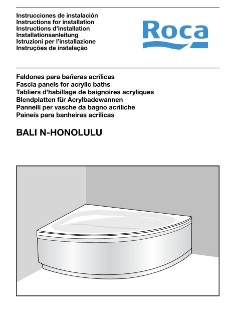
Faldones para bañeras acrílicas<br />
Fascia panels for acrylic baths<br />
Tabliers d’habillage de baignoires acryliques<br />
Blendplatten für Acrylbadewannen<br />
Pannelli per vasche da bagno acriliche<br />
Paineís para banheiras acrílicas<br />
<strong>BALI</strong> N-<strong>HONOLULU</strong><br />
1
ESPAÑOL<br />
INDICE<br />
Descripción del material ------------------------------------ 4<br />
Preparación de la bañera ------------------------------------ 4<br />
Comprobación de los conjuntos soporte del faldón ------- 4<br />
Montaje previo del faldón y marcado<br />
de líneas de referencia --------------------------------------- 4<br />
Montaje de los soportes laterales --------------------------- 4<br />
Montaje de los soportes frontales --------------------------- 4<br />
Montaje del faldón -------------------------------------------- 4<br />
ENGLISH<br />
CONTENTS<br />
Description of goods ----------------------------------------- 5<br />
Preparing the bath -------------------------------------------- 5<br />
Checking the panel's support units-------------------------- 5<br />
Pre-fitting the panel and marking the<br />
guidelines ----------------------------------------------------- 5<br />
Assambly the side supports ---------------------------------- 5<br />
Assambly the front supports --------------------------------- 5<br />
Fitting the panel ----------------------------------------------- 5<br />
FRANÇAIS<br />
SOMMAIRE<br />
E<br />
GB<br />
F<br />
Description du matériel -------------------------------------- 6<br />
Préparation de la baignoire --------------------------------- 6<br />
Vérification des ensembles de support du tablier---------- 6<br />
Montage préliminaire du tablier et traçage<br />
des lignes de repère ----------------------------------------- 6<br />
Montage des supports latéraux ------------------------------ 6<br />
Montage des supports avants-------------------------------- 6<br />
Montage du tablier ------------------------------------------ 6<br />
2<br />
DEUTSCH<br />
INHALTSVERZEICHNIS<br />
Inhalt der Verpackung -------------------------------------- 7<br />
Vorbereitung der Badewanne ------------------------------- 7<br />
Prüfung der befestigungsvorrichtungen für die verblendung 7<br />
VorMontage der verblendung und markieren<br />
der Bezugslinien --------------------------------------------- 7<br />
Montage der seitenbefestigungen --------------------------- 7<br />
Montage der Stirnbefestigungen----------------------------- 7<br />
Montage der verblendung ---------------------------------- 7<br />
ITALIANO<br />
INDICE<br />
Descrizione del materiale ----------------------------------- 8<br />
Preparazione della vasca ----------------------------------- 8<br />
Controllo dei gruppi di supporto del panello---------------- 8<br />
Montaggio preliminare del pannello<br />
e tracciatura delle linee di riferimento --------------------- 8<br />
Montaggio dei supporti laterali------------------------------- 8<br />
Montaggio dei supporti frontali ------------------------------ 8<br />
Montaggio del pannello -------------------------------------- 8<br />
PORTUGUÊS<br />
ÍNDICE<br />
D<br />
I<br />
P<br />
Descrição do material --------------------------------------- 9<br />
Preparação da banheira ------------------------------------- 9<br />
Verificação dos conjuntos suporte da proteção------------ 9<br />
Montagem prévia da proteção e marcação<br />
de linhas de referência -------------------------------------- 9<br />
Montagem dos suportes -------------------------------------- 9<br />
Montagem dos suportes frontaislaterais-------------------- 9<br />
Montagem da proteção ------------------------------------- 9
Fig. 1<br />
Abb. 1<br />
E<br />
Fig. 3<br />
Abb. 3<br />
D<br />
30<br />
5<br />
Fig. 5<br />
Abb. 5<br />
Honolulu Bali N<br />
D<br />
30<br />
70<br />
5<br />
225<br />
C<br />
C<br />
C<br />
C<br />
3<br />
Fig. 2<br />
Abb. 2<br />
Fig. 4<br />
Abb. 4<br />
Fig. 6<br />
Abb. 6
EE<br />
La bañera se habrá instalado previamente según las posibilidades<br />
contempladas en su propio manual de instalación. El cerramiento<br />
se realizará en cualquier caso siguiendo las instrucciones del<br />
presente manual.<br />
DESCRIPCIÓN DEL MATERIAL<br />
Una vez desembalado el faldón compruebe que ha recibido el<br />
material siguiente:<br />
- Faldón.<br />
- 2 Conjuntos de soportes montados.<br />
- 4 tacos de madera.<br />
- Bolsa de tornillería que contiene:<br />
4 tornillos.<br />
4 arandelas.<br />
4 capuchones.<br />
- Bolsa de tornillería que contiene:<br />
6 tacos SX6.<br />
6 tirafondos 60x5.<br />
2 apoyos superiores de varilla.<br />
2 discos de apoyo.<br />
- Este manual de instrucciones.<br />
PREPARACIÓN DE LA BAÑERA<br />
Comprobar que la bañera está nivelada a la altura de 520mm<br />
(Honolulu) y 542 (Bali N) para ser equipada con faldón según el<br />
Manual de Instalación.<br />
Si fuera necesario, se deberá corregir la regulación de las patas.<br />
Para iniciar la instalación del faldón la bañera debe estar correctamente<br />
instalada según las instrucciones dadas en el Manual de<br />
Instalación. Ante cualquier duda sobre la colocación de la bañera<br />
debe consultarse dicho manual.<br />
COMPROBACIÓN DE LOS CONJUNTOS SOPORTE<br />
DEL FALDÓN<br />
Compruebe que en la caja correspondiente están los dos conjuntos<br />
de soporte con todos los elementos montados y las tuercas de<br />
sujeción bien apretadas.<br />
En el caso de que por alguna manipulación no contemplada en este<br />
manual hubiera que partir de conjuntos soporte con elementos separados,<br />
se procederá al montaje de los mismos según indican las<br />
figuras citadas (fig. 1). Es muy importante montar todas las arandelas<br />
y todas las piezas en posición correcta, apretando las tuercas con<br />
firmeza.<br />
MONTAJE PREVIO DEL FALDÓN Y MARCADO DE LÍNEAS<br />
DE REFERENCIA<br />
Desembalar el faldón y colocarlo en la bañera en su posición correcta<br />
de instalación, con el borde superior del mismo apoyando<br />
en el borde interno de la bañera (fig. 2).<br />
Marcar una línea en el suelo, siguiendo el borde inferior exterior<br />
del faldón. Dicha línea servirá de referencia (descontando 5 mm)<br />
para comprobar la correcta posición de los tacos de fijación del<br />
faldón.<br />
4<br />
Asimismo, marque la posición de los 2 taladros frontales.<br />
Marcar igualmente la línea de contacto de los extremos del faldón<br />
con las paredes laterales.<br />
MONTAJE DE LOS SOPORTES LATERALES<br />
Colocar los tacos de madera en cada pared, según se ve en la<br />
figura 3.<br />
Hay que tener cuidado de colocar el trozo de madera de forma que<br />
presente el ángulo correcto para el montaje del faldón.<br />
MONTAJE DE LOS SOPORTES FRONTALES<br />
A. Bañeras con travesaños de nivelación.<br />
Los conjuntos soportes, previamente ensamblados y con las tuercas<br />
apretadas, forma un elemento rígido y fácil de manejar.<br />
Siguiendo la figura 4, montar dicho conjunto introduciendo el coliso<br />
del soporte horizontal en la varilla del pie M10, entre la arandela y<br />
el tubo cuadrado del travesaño de nivelación.<br />
¡Atención!: Antes de introducir directamente el coliso en la varilla,<br />
se debe colocar el extremo superior del conjunto, regulando la<br />
varilla roscada para que haga presión contra el borde interior de<br />
la bañera, junto con la corona de posicionamiento. Esto puede<br />
lograrse con facilidad haciendo girar todo el conjunto, pasando el<br />
coliso una vez situado el extremo superior del soporte.<br />
Regular las varillas de forma que el taco negro quede delante de<br />
la marca del taladro frontal efectuada en el suelo.<br />
El sistema de fijación del faldón se describe en el croquis a continuación<br />
(fig. 6).<br />
Regular los tacos girándolos para que el faldón quede vertical y<br />
los orificios del faldón coincidan sobre el taco correspondiente.<br />
Apretar a continuación la contratuerca.<br />
Atornillar los tacos de madera a la pared.<br />
B. Bañeras con bastidores laterales.<br />
Presentar el faldón y marcar en el suelo la proyección de los orificios<br />
de fijación (fig. 5).<br />
Atornillar los tacos de madera a la pared D y al suelo E (fig. 5)<br />
MONTAJE DEL FALDÓN<br />
Colocar los «clips» C en el borde de faldón de forma que esten<br />
enfrentados a los dos tubos soporte de la bañera. Se pueden<br />
desplazar, golpeando suavemente con un martillo.<br />
Antes de fijar cada faldón es muy importante colocar unas cuñas<br />
entre el suelo y el faldón para apretar con fuerza el faldón contra<br />
el borde de la bañera. Una vez asegurado esto, fijar el faldón con<br />
las arandelas, tornillos y tapones indicados.<br />
Si la bañera está empotrada dentro del revestimiento de la pared<br />
y se desea que el faldón quede por encima del mismo, cortar el<br />
faldón por el extremo que toca a la pared la dimensión necesaria<br />
por encima de dicho revestimiento. Utilizar una sierra de diente<br />
fino y lijar posteriormente para eliminar rebabas.<br />
Acabar a continuación el alicatado de las paredes.<br />
A continuación debe sellarse con silicona la unión entre la pared<br />
de la habitación y la bañera. Utilizar silicona base alcohol habitual<br />
de mercado.
GB<br />
These are fitted after installing the bath in accordance with the<br />
options given in the installation manual for the bath. The instructions<br />
in this manual are to be followed for finishing off the sides<br />
of the bath.<br />
DESCRIPTION OF THE GOODS<br />
After unpacking the panel, check that you have received these<br />
items:<br />
- The bath panel.<br />
- 2 Fully assembled support units.<br />
- 4 wooden hell.<br />
- Bag of fasteners containing:<br />
4 screws.<br />
4 plastic washer.<br />
4 plastic screw covers.<br />
- Bag of fasteners containing:<br />
6 SX6 wall plugs.<br />
6 screws 60x5.<br />
2 Upper support of rod 2 joints.<br />
- This manual.<br />
PREPARING THE BATH.<br />
Make sure that the top of the bath is level at 520 mm (Honolulu) and<br />
542 mm (Bali N) enabling the side panel to be fitted as explained<br />
in the Installation Manual.<br />
If necessary, adjust the bath’s feet to make it level.<br />
The bath must be correctly installed, in line with the instructions<br />
given in its Installation Manual, before starting to fit the side panel.<br />
If in doubt about how to install the bath, consult that manual.<br />
CHECKING THE PANEL’S SUPPORT UNITS<br />
Check that the two support units are in the box, with everything<br />
fitted on them and the lock nuts fully tightened.<br />
If you find that the support units have been disassembled, contrary<br />
to this manual, and you thus have to start with loose components,<br />
assemble them as shown in those figures (fig. 1). It is very important<br />
to fit all the washers and the various parts in the right position, and<br />
to tighten up all the nuts securely.<br />
PRE-FITTING THE PANEL AND MARKING THE GUIDE-<br />
LINES<br />
Unpack the panel and fit it in its proper place on the side of the bath,<br />
with its upper edge resting on the inside edge of the bath (fig. 2).<br />
Mark the floor along the bottom outside edge of the panel – that<br />
line will later be used as the reference line for finding the correct<br />
position for the blocks that hold the panel in place, which have to<br />
be 5 mm away from it.<br />
Then mark the position of the two drill-holes in the front.<br />
Lastly, mark the walls of the bathroom along the edges of the panel<br />
where it meets the walls.<br />
5<br />
ASSEMBLY THE SIDE SUPPORTS<br />
Place the wooden hells in each wall, as it is indicated in the figure<br />
3.<br />
Be careful to fit the piece of wood in such a way that it makes the<br />
correct angle for fitting the panel.<br />
ASSEMBLY THE FRONT SUPPORTS<br />
A. Bath with levelling crosspieces<br />
The support units, wich are aupplied fully assembled and with all<br />
its nuts tightened up, is a rigid unit that is easy to work with.<br />
Following fig. 4, fit this unit by inserting the slotted horizontal support<br />
onto the rod of the M10 foot, between the washer and the<br />
box-section tube of the cross-member used for levelling.<br />
Please note!: Before inserting the slot directly onto the rod, the top<br />
end of the unit must be fitted by ajusting the threaded rod to press<br />
against the inside edge of the bath together with its positioning<br />
crown. This can be done easily by turning the whole unit around and<br />
fitting the slotted part when the top of the support is in place.<br />
Adjust the rods so that the black block is to the front of the mark<br />
for the front drill hole that you made on the floor.<br />
The system for fitting the panel is detailed in the sketch below<br />
(Fig.6). Adjust the blocks by turning them so that the panel is left<br />
upright, with the panel drill holes in line with the corresponding<br />
block. Then tighten up the lock nut.<br />
Screw the wooden hells to the wall.<br />
The system for fitting the panel is detailed in the sketch below<br />
(fig. 6). Adjust the blocks by turning them so that the panel is left<br />
upright, with the panel drill holes in line with the corresponding<br />
block. Then tighten up the lock nut.<br />
B. Bath with lateral wings<br />
Offer up the skirt and mark the projection of the anchoring holes<br />
on the floor. (Fig. 5)<br />
Screw the wooden blocks to the wall D and to the floor E.(Fig. 5).<br />
ASSEMBLY THE PANEL<br />
Place those «clips» C in the panel border so that they are faced<br />
to the two rods of the bath. They can move, hitting smoothly with<br />
a hammer.<br />
Before fixing each panel finally in place, it is very important to insert<br />
wedges between the floor and the panel to push the panel firmly<br />
up against the edge of the bath. When it is, secure the panel with<br />
the washers, screws and caps shown.<br />
If the bath is built into the wall surfacing and you want the panel to<br />
go outside it, cut the panel along the edge that meets the wall just<br />
enough to leave that edge away from the wall finishing. Use a finetoothed<br />
saw, and sand down afterwards to remove any burrs.<br />
Then finish off the wall tiling.<br />
The joint between the bathroom wall and the bath must then be<br />
sealed. An ordinary alcohol-based silicone sealent is suitable for<br />
this purpose.
F<br />
Au préalable, la baignoire aura été installée selon l’une des formules<br />
envisagées dans la notice d’installation qui lui est consacrée.<br />
Quelle que soit la solution choisie, la pose de l’habillage devra être<br />
effectuée conformément aux instructions de la présente notice.<br />
DESCRIPTION DU MATÉRIEL<br />
Après avoir retiré le tablier de son emballage, vérifiez que vous<br />
avez reçu le matériel suivant:<br />
- Tablier d’habillage.<br />
- 2 Ensemble de support assemblé.<br />
- 4 enfer en bois.<br />
- Sachet de visserie contenant:<br />
4 vis.<br />
4 rondelle plastique.<br />
4 enjoliveurs en plastique.<br />
- Sachet de visserie contenant:<br />
6 chevilles SX6<br />
6 tire-fond 60x5.<br />
2 embase supérieure tige.<br />
2 joints.<br />
- Cette notice d’instructions<br />
PRÉPARATION DE LA BAIGNOIRE<br />
Vérifiez le niveau de la baignoire: pour pouvoir installer le tablier<br />
en suivant les instructions de cette notice, il faut que la hauteur de<br />
la baignoire soit égale à 520mm (Honolulu) au 542 mm (Bali N).Si<br />
nécessaire, rectifier le réglage des pieds.<br />
N’entreprenez d’installer le tablier que si la baignoire a été montée<br />
conformément aux instructions de la notice d’installation. En cas<br />
de doute à cet égard, reportez-vous à cette notice.<br />
VÉRIFICATION DES ENSEMBLES DE SUPPORT DU<br />
TABLIER<br />
Vérifiez le contenu du carton. Vous devez y trouver deux ensembles<br />
de support dont tous les éléments sont assemblés et les écrous<br />
serrés à bloc.<br />
Si, en raison d’une manipulation non envisagée dans cette notice,<br />
vous devez partir d’ensembles de support en éléments séparés,<br />
assemblez-les en vous aidant des schémas en question (figure 1).<br />
Veillez à ce que les rondelles et toutes les pièces soient à leur place<br />
et les écrous serrés à bloc.<br />
MONTAGE PRÉLIMINAIRE DU TABLIER ET TRAÇAGE<br />
DES LIGNES DE REPÈRE<br />
Retirez le tablier de son emballage et mettez-le en position contre<br />
la baignoire, arête supérieure reposant sur le rebord interne de<br />
celle-ci (figure 2).<br />
Tracez une ligne au sol en suivant l’arête inférieure externe du<br />
tablier. Ce trait vous servira de repère (moins 5mm) pour vérifier si<br />
les chevilles de fixation du tablier sont dans la bonne position.<br />
6<br />
Marquez également l’emplacement des 2 orifices avants.<br />
Tracez enfin une ligne de repère à l’endroit où les extrémités du<br />
tablier entrent en contact avec les parois latérales.<br />
MONTAGE DES SUPPORTS LATÉRAUX<br />
Placez les enfers en bois dans chaque mur, comme il est indiqué<br />
dans le schéma 3.<br />
Veillez à placer le morceau de bois de façon à ce qu’il présente<br />
l’angle approprié pour pouvoir monter le tablier.<br />
MONTAGE DES SUPPORTS AVANTS<br />
A. Baignoire avec niveler des traverses<br />
Les unités du support qui sont fournies se sont complètement<br />
assemblées et avec tout ses noix ont serré, est une unité rigide<br />
qui est facile de travailler avec.<br />
Pour le monter, reportez-vous au schéma 4: faites glisser le support<br />
horizontal rainuré autour de la tige du pied M10, entre la rondelle<br />
et le tube carré de la traverse de niveau.<br />
Attention: avant d’introduire le support rainuré, il faut placer<br />
l’extrémité supérieure de l’ensemble en réglant la tige filetée pour<br />
qu´elle fasse presion contre le rebord intérieur de la baignoire avec<br />
la couronne de positionnement. On y parvient facilement en faisant<br />
pivoter l’ensemble, puis, une fois l’extrémité supérieure du support<br />
mise en place, en introduisant le support rainuré.<br />
Ajuster les tiges de façon à ce que la cheville noire vienne se placer<br />
devant l’orifice avant percé dans le sol.<br />
Le croquis suivant montre le détail du système de fixation du tablier<br />
(fig. 6). Réglez les chevilles en les faisant tourner jusqu’à ce que<br />
le tablier soit à la verticale et que ses orifices coïncident avec la<br />
cheville correspondante. Serrez ensuite le contre-écrou.<br />
Vissez les enfers en bois au mur.<br />
B. Baignoire avec les ailes latérales<br />
Positionner la jupe et marquer sur le plancher la projection des<br />
trous de fixation (Fig. 5).<br />
Visser les chevilles en bois au mur D et au plancher E. (Fig. 5).<br />
MONTAGE DU TABLIER<br />
Placez ceci «clips» C dans la frontière du panneau afin qu’en face<br />
d’ils sont aux deux tringles de la baignoire. Ils peuvent déplacer,<br />
en frappant doucement avec un marteau.<br />
Avant de fixer les éléments, il faut absolument glisser des coins<br />
entre le sol et le tablier, afin que ce dernier vienne appuyer tout<br />
contre le bord de la baignoire, après quoi on peut mettre en place<br />
les rondelles, les vis et leurs caches.<br />
Quand la baignoire est encastrée, si l’on veut que le tablier dépasse<br />
du revêtement mural, il faut en découper l’extrémité en contact<br />
avec le mur à au-dessus du revêtement. Utilisez une scie à fines<br />
dents, puis poncez soigneusement.<br />
Ensuite, finissez de carreler les murs.<br />
Scelllez ensuite la baignoire au mur à l’aide de silicone de type<br />
courant à base d’alcool.
D<br />
Die Badewanne ist vorher gemäß den in ihrer eigenen Montageanleitung<br />
genannten Möglichkeiten aufgestellt worden. Der Abschluss<br />
der Montage muss in jedem Fall auf der Grundlage der Anweisungen<br />
dieser Anleitung erfolgen.<br />
INHALT DER VERPACKUNG<br />
Überprüfen Sie nach dem Auspacken der Verblendung, dass Sie<br />
das folgende Material erhalten haben:<br />
-Verblendung.<br />
-2 Vormontierte rechte Befestigungsvorrichtungen.<br />
-4 hölzerne Hölle.<br />
-Beutel mit Befestigungsmaterial enthält:<br />
4 Schrauben.<br />
4 Unterlegscheibe.<br />
4 Kunststoffabdeckkappen.<br />
-Beutel mit Befestigungsmaterial enthält:<br />
6 Dübel SX6.<br />
6 Schraubenbolzen 60x5.<br />
2 Obere Gestängeauflage.<br />
2 Dichtungs.<br />
-Diese Anleitung.<br />
VORBEREITUNG DER BADEWANNE<br />
Überprüfen Sie bitte, dass die Badewanne auf der Höhe 520mm<br />
(Honolulu) und 542mm (Bali N) in Waage steht, damit die Verblendung<br />
wie in der Aufbauanleitung angegeben montiert werden<br />
kann.<br />
Bei Bedarf müssen die Füsse neu eingestellt werden.<br />
Die Badewanne liegt mit ihren beiden Ausrichtbalken auf dem<br />
Boden auf.<br />
Um mit dem Einbau der Verblendung beginnen zu können, muss die<br />
Badewanne korrekt gemäß der Anweisungen in der Montageanleitung<br />
aufgestellt sein. Bei jeder Unklarheit im Hinblick auf die Aufstellung<br />
der Wanne, muss diese Anleitung zu Rate gezogen werden.<br />
PRÜFUNG DER BEFESTIGUNGSVORRICHTUNGEN<br />
FÜR DIE VERBLENDUNG<br />
Überprüfen Sie, dass in der entsprechenden Kiste beide Befestigungsvorrichtungen<br />
mit allen vormontierten Elementen und<br />
angezogenen Feststellmuttern vorhanden sind.<br />
Sollten aufgrund irgendeiner in dieser Anleitung nicht abzusehenden<br />
Veränderung die Befestigungsvorrichtungen mit getrennten<br />
Bestandteilen vorliegen, werden sie gemäß der Abbildungen zusammengebaut<br />
(Abb 1). Es ist sehr wichtig, alle Unterlegscheiben<br />
sowie anderen Teile an der richtigen Position einzubauen und die<br />
Muttern kraftvoll anzuziehen.<br />
VORMONTAGE DER VERBLENDUNG UND MARKIE-<br />
REN DER BEZUGSLINIEN<br />
Packen Sie die Verblendung aus und setzen Sie sie in der korrekten<br />
Einbauposition auf die Badewanne, wobei die Oberkante der<br />
Verblendung auf der Innenkante der Wanne aufliegt (Abb 2).<br />
Markieren Sie eine Linie auf dem Boden, wobei Sie den unteres<br />
äußeren Rand der Verblendung als Bezugspunkt wählen. Diese Linie<br />
dient zu Ihrer Orientierung (nach Abzug von 5 mm), um die korrekte<br />
Lage der Befestigungsdübel der Verblendung zu überprüfen.<br />
7<br />
Außerdem ist die Lage der 2 Bohrungen an der Stirnseite zu<br />
markieren.<br />
Markieren Sie auch noch die Berührungslinie der Verblendungsenden<br />
mit den Seitenwänden.<br />
MONTAGE DER SEITENBEFESTIGUNGEN<br />
Setzen Sie die hölzernen Höllen in jede Mauer, wie es in der Abbildung<br />
3 gezeigt wird.<br />
Man muss darauf achten, das Holzstück so einzusetzen, dass es<br />
den korrekten Winkel für den Einbau der Verblendung aufweist.<br />
MONTAGE DER STIRNBEFESTIGUNGEN<br />
A. Badewanne mit dem Planieren von Querstücken<br />
Die Hilfs Einheiten, die vollständing geliefert werden, setzten zusammen<br />
und mit all sinen Nüssen,die aufwärts festgezogen werden,<br />
ist eine starre Einheit, die leicht, mit zu arbeiten ist.<br />
Nach Abbildung 4 montieren Sie diese Vorrichtung, indem Sie den<br />
Schieber der waagrechten Befestigung zwischen der Unter-legscheibe<br />
und dem quadratischen Rohr des Ausrichtbalkens in den<br />
Stift des Fusses M10 einführen.<br />
Vorsicht!: Bevor Sie den Schieber direkt in den Stift einführen,<br />
müssen Sie den oberen Rand der Vorrichtung mit Hilfe des Gewindestifts<br />
gegen den Innenrand der Wanne zusammen mit dem Positionierungskranz<br />
cinstellen. Dies läßt sich leicht erreichen, indem<br />
man die ganze Vorrichtung dreht und den Bolzen erst durchsteckt,<br />
wenn der obere Rand der Befestigung festsitzt.<br />
Stangen einstellen so reguliert werden, dass der schwarze Dübel<br />
vor der Markierung des Bohrlochs an der Stirnseite auf dem Boden<br />
sitzt.<br />
Das Befestigungssystem der Verblendung wird in der folgenden<br />
Skizze beschrieben (Abb. 6). Regulieren Sie die Dübel durch<br />
Drehen, damit die Verblendung waagrecht steht und die Verblendungslöcher<br />
auf dem entsprechenden Dübel liegen. Dann ziehen<br />
Sie die Kontermutter an.<br />
Schrauben Sie die Hölzernen Höllen zur Mauer.<br />
B. Badewanne mit seitlichen Flügeln<br />
Schürze probeweise ausrichten und die Positon der Befestigungslöcher<br />
auf dem Boden anzeichnen. Abb.5.<br />
Holzdübel in Wand D und Boden Eeinschrauben. (Abb. 5).<br />
MONTAGE DER VERBLENDUNG<br />
Sentzen Sie jene «clips»C im Tafel-Rand, damit sie zu den zwei<br />
Stäben der Badewanne angesehen werden. Sie Können sich<br />
bewegen und Können glatt mit einen Hammer stoßen.<br />
Bevor Sie jede Verblendung anziehen, ist es sehr wichtig, dass<br />
Sie Keile zwischen den Boden und die Verblendung legen, um die<br />
Verblendung fest an den Badewannenrand anzudrücken. Nachdem<br />
dies sichergestellt ist, befestigen Sie die Verblendung mit den<br />
Unterlegscheiben, Schrauben und angegebenen Abdeckkappen.<br />
Wenn die Badewanne in die Wandverkleidung eingebaut ist und Sie<br />
möchten, dass die Verblendung damit abschließt, beschneiden Sie<br />
die Verblendung an dem Ende, das die Wand berührt, soviel, damit sie<br />
über der besagten Verkleidung bleibt. Benutzen Sie eine feinzahnige<br />
Säge und feilen Sie anschließend ab, um Grate zu beseitigen.<br />
Anschließend beenden Sie das Kacheln der Wände.<br />
Zum Abschluß muß die Fuge zwischen Wand und Wanne mit Silikon<br />
versiegelt werden. Hierzu kann handelsübliches alkoholhaltiges<br />
Silikon verwendet werden.<br />
Die Konstruktion der Wanne und Schürze ist so ausgelegt um eine<br />
optimale technische Installation zu gewährleisten. Dies bedeutet<br />
ungleiche Bodenverhältnisse sowie andere Toleranzen müssen<br />
überbrückt werden. Außerdem soll jede Wanne belüftet werden,<br />
um Kondenswasser -und andere Feuchtigkeiten optimal zu trocknen<br />
und Hygiene zu gewährleisten.<br />
Aus diesem Grund muss die Schürze an die Badewanne oben<br />
angepasst werden und es entsteht am Fußboden ein technisch<br />
gewollter Abstand zum Belüften und zum Ausgleichen. Hier steht<br />
Funktion über visuellem Design.<br />
Bei Whirlpools darf diese Fuge im keinem Fall geschlossen werden.<br />
Bitte beachten Sie diese Montageanweisung da sonst Gewährleistungen<br />
ausgeschlossen sind.
I<br />
La vasca dovrà già essere stata collocata, secondo le possibilità<br />
contemplate nel Manuale per l’Installazione. Il serramento dovrà<br />
essere in qualsiasi caso realizzato seguendo le istruzioni contenute<br />
nel presente manuale.<br />
DESCRIZIONE DEL MATERIALE<br />
Una volta disimballato il pannello, controllare se si è ricevuto il<br />
seguente materiale:<br />
-Pannello.<br />
-2 Gruppo di supporto montato.<br />
-4 Tassali in legno.<br />
-Sacchetto di viteria contenente:<br />
4 vite.<br />
4 rondella in plastica.<br />
4 tappi di plastica.<br />
-Sacchetto di viteria contenente:<br />
6 tasselli SX6.<br />
6 viti tirafondo 60x5.<br />
2 suporto superiore asta.<br />
2 guarnizioni.<br />
-Il presente Manuale d’Istruzioni.<br />
PREPARAZIONE DELLA VASCA<br />
Controllare che la vasca si trovi livellata a un’altezza di 520mm<br />
(Honolulu) i 542mm (Bali N) per procedere alla collocazione del<br />
pannello, come indicato nel Manuale d’Istruzioni.<br />
Se necessario, modificare la regolazione dei piedini.<br />
Per iniziare l’installazione del pannello, la vasca deve essere correttamente<br />
installata secondo le istruzioni fornite nel Manuale per<br />
l’Installazione. Per qualsiasi dubbio riguardante la collocazione della<br />
vasca, consultare detto manuale.<br />
CONTROLLO DEI GRUPPI DI SUPPORTO DEL PANNE-<br />
LLO<br />
Controllare che nella scatola corrispondente si trovino i due gruppi<br />
di supporto con tutti gli elementi montati ed i dadi di fissaggio ben<br />
serrati.<br />
Se per qualche motivo non contemplato in questo manuale si deve<br />
partire da gruppi di supporto con elementi separati, si procederà<br />
al montaggio degli stessi come indicato nelle figure corrispondenti<br />
(figura 1). È di particolare importanza montare tutte le rondelle e<br />
tutti i pezzi nella giusta posizione, serrando i dadi con forza.<br />
MONTAGGIO PREVIO DEL PANNELLO E TRACCIATU-<br />
RA DELLE LINEE DI RIFERIMENTO<br />
Disimballare il pannello e collocarlo nella vasca nella posizione<br />
corretta per l’installazione, con il bordo superiore dello stesso<br />
appoggiato sul bordo interno della vasca (figura 2).<br />
Tracciare una linea sul pavimento, seguendo il bordo inferiore<br />
esterno del pannello. Detta linea servirà come riferimento (scontando<br />
5 mm) per verificare il corretto posizionamento dei tasselli<br />
di fissaggio del pannello.<br />
8<br />
Allo stesso modo, marcare la posizione dei due fori frontali.<br />
Tracciare anche la linea di contatto delle estremità del pannello<br />
con le pareti laterali.<br />
MONTAGGIO DEI SUPPORTI LATERALI<br />
Metta gli inferni di legno in ogni muro, come è indicato nella figura<br />
3.<br />
Collocare il pezzo di legno in modo che presenti l’angolo adeguato<br />
per il montaggio del pannello.<br />
Montaggio dei supporti frontali<br />
A. Vasca con traverse del livellamento.<br />
Le unità dell’appoggio che sono approvvigionate assemblarono<br />
pienamente e con tutti i suoi noci stretti su, è un’unità rigida che<br />
è facile lavorare con.<br />
Seguendo la figura 4, montare detto gruppo introducendo l’asola<br />
del supporto orizzontale nella barra del piede M10, tra la rondella<br />
e il tubo quadrato della traversa di livellamento.<br />
Attenzione: prima d’introdurre direttamente l’asola nella barra, collocare<br />
l’estremità superiore del gruppo regolando l’asta filettata in<br />
modo che faccia pressione sul bordo interino della vasca assieme<br />
alla corona di posizionamento. Ciò si può conseguire con facilità<br />
facendo ruotare tutto il gruppo e facendolo passare per l’asola una<br />
volta collocata l’estremità superiore del supporto.<br />
Regolare le barre in modo che il tassello nero rimanga davanti al<br />
riferimento del foro frontale realizzato sul pavimento.<br />
Il sistema di fissaggio del pannello viene illustrato nel disegno che<br />
segue (fig. 6). Regolare i tasselli ruotandoli, in modo che il pannello<br />
rimanga verticale e i fori del pannello coincidano con il tassello<br />
corrispondente. Serrare quindi il controdado.<br />
B. Vasca con ali laterali<br />
Posizionare il pannello e marcare sul pavimento la proiezione dei<br />
fori di fissaggio (Fig. 5).<br />
Avvitare i tasselli di legno alla parete D e al pavimento E. (Fig. 5).<br />
MONTAGGIO DEL PANNELLO<br />
Metta quelli «abbranca»C nel confine del pannello così che loro<br />
sono affrontati alle due verghe del bagno. Loro possono muoversi,<br />
mentre copendo agevolmente con un martello.<br />
Prima di fissare ogni pannello è molto importante collocare dei<br />
cunei tra il pavimento e il pannello per serrare con forza il pannello<br />
contro il bordo della vasca. Una volta assicurato questo, fissare il<br />
pannello con le rondelle, le viti ed i tappi indicati.<br />
Se la vasca è incassata nel rivestimento della parete e si desidera<br />
che il pannello rimanda al di sopra di questo, tagliare l’estremità<br />
del pannello che tocca la parete di quel tanto che basta perché<br />
questo rimanga circa al disopra di detto rivestimento. Utilizzare<br />
una sega a dentatura molto sottile e carteggiare posteriormente<br />
per eliminate qualsiasi irregolarità.<br />
Terminare quindi la piastrellatura delle pareti.<br />
Sigillare quindi con silicone l’unione tra la parete della stanza e la<br />
vasca. Utilizzare silicone a base di alcool reperibile presso qualsiasi<br />
negozio specializzato.
d<br />
P<br />
A banheira deve ser previamente instalada conforme as possibilidades<br />
apresentadas no respectivo manual de instalação. O<br />
remate realizar-se-á em qualquer caso seguindo as instruções do<br />
presente manual.<br />
DESCRIÇÃO DO MATERIAL<br />
Depois de desembalada a protecção, verifique se recebeu o seguinte<br />
material:<br />
-Protecção.<br />
-2 Conjunto de suporte montados.<br />
-4 inferno de madeira.<br />
-Bolsa de quinquilharia que contém:<br />
4 parafusos.<br />
4 anilhas de plástico.<br />
4 tampões de plástico.<br />
-Bolsa de quinquilharia que contém:<br />
6 buchas SX6.<br />
6 tirafundos 60x5.<br />
2 apoio superior, vareta.<br />
2 juntass.<br />
-Este manual de instruções.<br />
PREPARAÇÃO DA BANHEIRA<br />
Verificar se a banheira está nivelada à altura de 520 mm (Honolulu)<br />
y 542mm (Bali N) para ser equipada com protecção conforme o<br />
Manual de Instalação.<br />
Se for necessário, dever-se-á corrigir a regulação das pernas.<br />
Para iniciar a instalação da protecção a banheira deve estar correctamente<br />
instalada conforme as instruções apresentadas no<br />
Manual de Instalação. Perante qualquer dúvida sobre a colocação<br />
da banheira deve consultar-se o referido manual.<br />
VERIFICAÇÃO DOS CONJUNTOS SUPORTE DA PRO-<br />
TECÇÃO<br />
Verifique se na caixa correspondente estão os dois conjuntos de<br />
suporte com todos os elementos montados e as porcas de fixação<br />
bem apertadas.<br />
No caso de, por alguma manipulação não contemplada neste<br />
manual, se tiver que partir de conjuntos suporte com elementos<br />
separados, proceder-se-á à montagem dos mesmos conforme<br />
indicam as figuras citadas (fig. 1). É muito importante montar todas<br />
as anilhas e todas as peças na posição correcta, apertando<br />
as porcas com firmeza.<br />
MONTAGEM PRÉVIA DA PROTECÇÃO E MARCAÇÃO<br />
DE LINHAS DE REFERÊNCIA<br />
Desembalar a protecção e colocá-la na banheira na sua posição<br />
correcta de instalação, com a borda superior da mesma apoiado<br />
na borda interior da banheira (fig. 2).<br />
Marcar uma linha no solo, seguindo a borda inferior exterior da<br />
protecção. Essa linha servirá de referência (descontando 5 mm)<br />
9<br />
para verificar a posição correcta das buchas de fixação da protecção.<br />
Deste modo, marque a posição dos 2 orifícios frontais.<br />
Marcar igualmente a linha de contacto das extremidades da protecção<br />
com as paredes laterais.<br />
MONTAGEM DOS SUPORTES LATERAIS<br />
Coloque os infernos de madeira em cada parede, como é indicado<br />
na figura 3.<br />
Tem que ter-se o cuidado de colocar o pedaço de madeira de<br />
forma a que apresente o ângulo correcto para a montagem da<br />
protecção.<br />
MONTAGEM DOS SUPORTES FRONTAIS<br />
A. Banheira com sanefas niveladoras<br />
As unidades de apoio que são providas completamente ajuntaram<br />
e com todas suas nozes apertadas para cima, é uma unidade rígida<br />
que é fácil trabalhar com.<br />
Seguindo a figura 4, montar esse conjunto introduzindo a calha<br />
do suporte horizontal na vareta do pé M10, entre a anilha e o tubo<br />
quadrado do travessão de nivelamento.<br />
¡Atenção!: Antes de introduzir directamente a calha na vareta, debe<br />
colocar-se a extremidade superior regulando a vareta roscada para<br />
que faça pressão contra a borda interior da banheira juntamente<br />
com a coroa de posicionamento. Isto pode ser conseguido com<br />
facilidade fazendo girar todo o conjunto, passando a calha depois<br />
de colocada a extremidade superior do suporte.<br />
Regular as varetas de forma a que a bucha preta fique diante da<br />
marca do orifício frontal efectuada no solo.<br />
Depois de montados os conjuntos suporte, as buchas de fixação<br />
deverão estar alinhadas com os orifícios frontais da protecção e<br />
orientados segundo a curva interna da protecção.<br />
Atarraxe os infernos de madeira à parede.<br />
B. Banheira com asas laterais<br />
Colocar o tapamento lateral e marcar no chão os orifícios de<br />
fixação (Fig. 5).<br />
Aparafusar os pernos de madeira à parede D e ao chão E.<br />
(Fig. 5).<br />
MONTAGEM DA PROTECÇÃO<br />
O sistema de fixação da protecção é descrito no esboço que se<br />
segue (fig. 6). Regular as buchas rodando-as para que a protecção<br />
fique vertical e os orifícios da protecção coincidam sobre a bucha<br />
correspondente. Em seguida, apertar a contra-porca.<br />
Antes de fixar cada protecção é muito importante colocar umas<br />
cunhas entre o solo e a protecção para apertar com força a<br />
protecção contra a borda da banheira.<br />
Depois de assegurar isto, fixar a protecção com as anilhas,<br />
parafusos e tampões indicados.<br />
Se a banheira estiver encastrada dentro do revestimento da parede<br />
e se desejar que a protecção fique por cima do mesmo, cortar a<br />
protecção pela extremidade que toca a parede o suficiente para<br />
que fique a acima do referido revestimento. Utilizar uma serra de<br />
dente fino e lixar posteriormente para eliminar rebarbas.<br />
Em seguida, acabar a colocação dos azulejos das paredes.<br />
Em seguida, deve selar-se a união entre a parede do compartimento<br />
e a abnheira com silicone. Utilizar silicone à base de álcool,<br />
existente no mercado.
060203<br />
289452i<br />
<strong>Roca</strong> Sanitario, S.A.<br />
Avda. Diagonal, 513<br />
08029 Barcelona<br />
España<br />
<strong>Roca</strong> S.R.L.<br />
Via Leonardo da Vinci, 24<br />
20080 Casarile (Milano)<br />
Italia<br />
Tel. +39.02.900.251<br />
Fax.+39.02.905.21.74<br />
<strong>Roca</strong> Cerâmica e Comercio, S.A.<br />
Serviços Comerciais<br />
Rua José Duarte Lexim, Lote 6<br />
2675-393 Odivelas Codex<br />
Apartado de Correios 16<br />
2676-901 Odivelas Codex<br />
Portugal<br />
Tel. +351.21.937.94.30<br />
Fax.+351.21.937.94.31<br />
<strong>Roca</strong> Limited<br />
Samson Road<br />
Hermitage Ind. Estate<br />
Coalville, Leics. LE67 3FP<br />
United Kingdom<br />
Tel. +44.(0)1530.83.00.80<br />
Fax.+44.(0)1530.83.00.10<br />
ROCA Maroc, S.A.<br />
Route de Marrakech, km 2.5<br />
B. P. 571 - 26000 - Settat<br />
Maroc<br />
Telf : +212.(0)23.40.59.41<br />
+212.(0)23.40.03.39<br />
Fax : +212.(0)23.40.59.42<br />
12<br />
<strong>Roca</strong> GmbH<br />
Feincheswiese 17<br />
56424 Staudt<br />
Deutschland<br />
Tel. +49.(0)2602.93610<br />
Fax.+49.(0)2602.936.122<br />
<strong>Roca</strong> Polska Sp. z o. o.<br />
ul. Wyczolkowskiego 20,<br />
44-109 Gliwice<br />
Polska<br />
Tel. +48.(0)32 339 41 00<br />
Fax.+48.(0)32 339 41 01<br />
<strong>Roca</strong> Argentina S.A<br />
Camino General Belgrano, 2873<br />
1824 - Lanús Este<br />
Buenos Aires<br />
Argentina<br />
Tel. +54.(0)114.230.96.39<br />
Fax:+54.(0)114.246.95.56<br />
<strong>Roca</strong> S.A.R.L.<br />
BP 90422<br />
95005 Cergy Pontoise Cedex<br />
France<br />
Tél. +33.(0)1.34.40.39.00<br />
Fax.+33.(0)130.37.02.65<br />
+33.(0)134.64.13.55<br />
Kalevit <strong>Roca</strong> Saniter Seramik Sanayi, A.S.<br />
Büyükdere Cad.<br />
Kaleseramik Binasi<br />
80620 Levent – Istanbul<br />
Turkey<br />
Tel. +90.212.270.70.00<br />
Fax.+90.212.268.68.89