woodcrest™& woodmoor™ shingles installation instructions
woodcrest™& woodmoor™ shingles installation instructions
woodcrest™& woodmoor™ shingles installation instructions

Create successful ePaper yourself
Turn your PDF publications into a flip-book with our unique Google optimized e-Paper software.
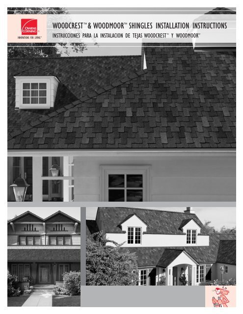
WOODCREST & WOODMOOR SHINGLES INSTALLATION INSTRUCTIONS<br />
INSTRUCCIONES PARA LA INSTALACION DE TEJAS WOODCREST Y WOODMOOR
Application Instructions:<br />
Before installing this product, check local building codes for their<br />
roofing requirements.<br />
These laminated <strong>shingles</strong> are designed for new or reroofing work over<br />
any properly built and supported wood roof deck having adequate<br />
nail holding capacity and a smooth surface. Check local building codes<br />
regarding deck load limits. Because Owens Corning Woodcrest /<br />
Woodmoor <strong>shingles</strong> are 360/465 avg. wt./sq., it must be determined if<br />
the roof frame can support workers and the weight of the <strong>shingles</strong>. It<br />
may not be feasible to apply the product over an existing shingle roof.<br />
Precautionary Note:<br />
The manufacturer will not be responsible for problems resulting from<br />
any deviation from the recommended application <strong>instructions</strong> and the<br />
following precautions:<br />
Roof Top Loading: Lay shingle bundles flat. Do not bend over the ridge.<br />
Roof Deck:<br />
6" Maximum roof deck boards<br />
Minimum 3 ⁄8" plywood<br />
Minimum 7 ⁄16" OSB<br />
Regardless of deck type used, the roofing installer must:<br />
1. Install the deck material in strict compliance with the deck<br />
manufacturer’s <strong>instructions</strong>.<br />
2. Prevent the deck from getting wet before, during and after <strong>installation</strong>.<br />
Ventilation: Must meet or exceed FHA Minimum Property Standards.<br />
Handling: Use extra care in handling <strong>shingles</strong> when the temperature is<br />
below 40°F.<br />
Storage: Store in a covered ventilated area at a maximum temperature of<br />
110°F. Stack in a flat fashion (maximum of 10 bundles high). Protect <strong>shingles</strong><br />
from weather when stored at the job site. Do not store near steam pipes,<br />
radiators, etc.<br />
Nails must be corrosion-resistant, 11- or<br />
12-gauge, with heads at least 3 ⁄8" in diameter.<br />
Staples must be 16-gauge minimum, 15 ⁄16"<br />
minimum crown width and sufficient length<br />
to penetrate 3 ⁄4" into wood decking or through<br />
APA-rated roof sheathing. Staples are to be<br />
corrosion protected.<br />
All Fasteners must penetrate at least 3 ⁄4"<br />
into the wood deck or completely through<br />
plywood sheathing.<br />
Notice: Owens Corning recommends the use<br />
of nails as the preferred method of attaching <strong>shingles</strong><br />
to wood decking or other nailable surface.<br />
Instrucciones para la aplicación:<br />
Antes de instalar este producto, consulte los códigos de construcción<br />
locales para informarse sobre los requisitos de techado.<br />
Estas tejas laminadas fueron diseñadas para techar por primera vez<br />
o retechar cualquier entablonado de techo de madera apoyado y<br />
correctamente construido, siempre que tenga capacidad de retención<br />
de clavos y una superficie lisa. Consulte los códigos de construcción<br />
locales sobre los límites de carga del entablonado. Debido a que las<br />
tejas Woodcrest /Woodmoor de Owens Corning pesan en promedio<br />
360/465 libras pies/2, es necesario determinar si la estructura del techo<br />
puede sostener a los trabajadores y el peso de las tejas. Quizás no sea<br />
posible aplicar el producto sobre un techo de tejas existentes.<br />
Nota de precaución:<br />
El fabricante no será responsable de problemas que sean consecuencia<br />
de no seguir exactamente las instrucciones de aplicación recomendadas<br />
y las siguientes precauciones:<br />
Carga sobre techo: Coloque los grupos de tejas de manera plana sobre<br />
el techo. No los doble sobre la cumbrera.<br />
Entablonado de techo:<br />
6 pulg. como máximo para tablas de entablonado<br />
3 ⁄8 pulg. como mínimo para madera terciada<br />
7 ⁄16 pulg. como mínimo para paneles de fibra orientada<br />
Cualquiera que sea el tipo de entablonado utilizado, el instalador debe:<br />
1. Instalar el material del entablonado siguiendo estrictamente las<br />
instrucciones del fabricante del entablonado.<br />
2. Evitar que el entablonado se moje antes, durante y después de<br />
la instalación.<br />
Ventilación: Debe cumplir o exceder las normas mínimas para propiedades<br />
establecidas por el FHA.<br />
Manipulación: Tenga mucho cuidado al manipular las tejas cuando la temperatura<br />
sea inferior a 40°F.<br />
Almacene: En un área cubierta y ventilada a una<br />
temperatura no mayor de 110°F/43°C. Apilar<br />
de manera plana (grupos con un máximo de<br />
10 tejas). Proteja las tejas del clima cuando las<br />
almacene en el lugar de trabajo. No almacene<br />
cerca de tuberías de vapor, radiadores, etc.<br />
Los clavos deben ser inoxidables, de calibre 11<br />
ó 12, con cabezas de por lo menos 3 ⁄8 pulg. de<br />
diámetro. Las grapas deben ser, como mínimo,<br />
de calibre 16 con un ancho de corona de al<br />
menos 15 ⁄16 pulg. y una longitud suficiente para penetrar 3 ⁄4 pulg. en el entablonado<br />
de madera o a través de un revestimiento de techo que cumpla<br />
con las normas APA. Las grapas deben ser a prueba de corrosión.<br />
Todos los fijadores deben penetrar al menos 3 ⁄4 pulg. en el entablonado de<br />
madera o completamente a través del recubrimiento de madera terciada.<br />
Aviso: Owens Corning recomienda el uso de clavos como método<br />
preferido para fijar tejas a entablonados de madera o a otras superficies<br />
aptas para clavos.<br />
1
1<br />
2<br />
2<br />
Specialty Eave Flashing:<br />
WeatherLock ® underlayment or<br />
equivalent eave and flashing membrane<br />
applied to a point at least 24" beyond<br />
interior wall line. See manufacturer’s<br />
<strong>installation</strong> <strong>instructions</strong>. See Fig. 1.<br />
Underlayment:<br />
Standard Slope (4" in 12" or more):<br />
Application of underlayment, metal drip<br />
edges, and eaves flashing: See Fig. 2.<br />
Low Slope (2" in 12" to less than 4" in<br />
12"): Application of underlayment and<br />
metal drip edges: See Fig. 2A.<br />
1<br />
2<br />
Revestimiento especial<br />
para alero:<br />
Membrana de revestimiento y alero<br />
WeatherLock ® reforzamiento o similar,<br />
aplicada en un punto al menos 24 pulg.<br />
más allá de la línea interior de la pared.<br />
Vea las instrucciones de instalación del<br />
fabricante. Vea la Fig. 1.<br />
Capa inferior:<br />
Pendiente estándar (4 pulg. cada 12<br />
pulg. o más): Aplicación de capa inferior,<br />
bordes de goteo metálicos y revestimiento<br />
de alero: Vea la Fig. 2.<br />
Pendiente baja (2 pulg. cada 12 pulg.<br />
hasta menos de 4 pulg. cada 12 pulg.):<br />
Aplicación de capa inferior y bordes<br />
de goteo metálicos: Vea la Fig. 2A.
Starter Course:<br />
3 Left Rake Application: Cut 35" off from<br />
3<br />
the first bottom starter piece. Fasten<br />
the remaining 5" x 133 ⁄8" to the deck<br />
as shown in Fig. 3, followed by a full<br />
133 ⁄8" x 40" starter piece to the deck<br />
with 5 fasteners as shown.<br />
Right Rake Application: Cut 5" off from<br />
the first bottom starter piece. Fasten<br />
the remaining 35" x 133 ⁄8" to the deck<br />
as shown in Fig. 3, followed by a full<br />
133 ⁄8" x 40" starter piece to the deck<br />
with 5 fasteners as shown.<br />
Caution: Using shingle products other<br />
than WoodStart Starter Strip for the<br />
starter course may result in a color<br />
variation at the lower edge of the roof.<br />
Starter Course<br />
Fig. 3 Hilera inicial<br />
Left Rake Application<br />
Aplicación izquierda del inclinación<br />
Rake edge<br />
Borde de viga inclinada<br />
35"<br />
Removed<br />
Quitara 40" Full Starter<br />
5" Pieza de inicio de 40 pulg.<br />
Right Rake Application<br />
Aplicación izquierda del inclinación<br />
Nail area<br />
Área de clavos<br />
Asphalt saturated<br />
felt underlayment<br />
Asfalte saturado<br />
felpa reforzamiento<br />
Nail area Área de clavos<br />
Rake edge<br />
Borde de viga inclinada<br />
40" Full Starter<br />
Starter strip is flush Pieza de inicio completa<br />
with drip edges a nival borde de goteo<br />
Standard Fastening Pattern<br />
Fig. 4 Esquema de fijación estándar<br />
35" 5"<br />
Removed<br />
Quitara<br />
4<br />
Shingle Fastening:<br />
Standard Fastening Pattern:<br />
Place fasteners in nail area. See Fig. 4.<br />
4<br />
1/2"<br />
14 1/4"<br />
40"<br />
11/2" Offset cuts<br />
11/2"<br />
Cortes de desplazamiento<br />
Nails<br />
Clavos<br />
1/2"<br />
Nail area<br />
Área de clavos<br />
Hilera inicial:<br />
Aplicación de la inclinación izquierda:<br />
Corte 35 pulg. de la parte superior de<br />
la pieza de inicio. Sujete la parte restante<br />
(5 pulg. x 133 ⁄8 pulg.) al techo como se<br />
muestra en la Fig. 3 y luego sujete una<br />
pieza de inicio completa (133 ⁄8 pulg. x 40<br />
pulg.) al techo con 5 fijadores como<br />
se indica.<br />
Aplicación de la inclinación derecha:<br />
Corte 5 pulg. de la parte superior de<br />
la pieza de inicio. Sujete la parte restante<br />
(35 pulg. x 133 ⁄8 pulg.) al techo como se<br />
muestra en la Fig. 3 y luego sujete una<br />
pieza de inicio completa (133 ⁄8 pulg. x 40<br />
pulg.) al techo con 5 fijadores como<br />
se indica.<br />
Precaución: Utilizar otros productos<br />
de tejas distintos a las hileras de inicio<br />
WoodStart al momento de armar<br />
la hilera inicial puede ocasionar una<br />
variación del color del extremo inferior<br />
del techo.<br />
Fijación de tejas:<br />
Esquema de fijación estándar:<br />
Coloque los fijadores en el área de<br />
clavos. Vea la Fig. 4.<br />
3
Mansard or Steep Slope Fastening Pattern<br />
5 Fig. 5 Esquema de fijación para mansardas o pendientes agudas 5<br />
Mansard or Steep Slope<br />
Fastening Pattern:<br />
See Fig. 5.<br />
REQUIRED: For slopes exceeding<br />
60 degrees or 21 inches per foot,<br />
9 nails are required with 5 in the nail<br />
area and 4 placed above tab cutouts.<br />
1. Position the first course shingle<br />
applying 5 nails in the nail area.<br />
2. Temporarily position the second<br />
course shingle above to determine<br />
the location for the additional<br />
4 fasteners.<br />
3. Once you have added the additional<br />
fasteners in the tab area, apply<br />
4 spots of asphalt cement under<br />
each tab and press in place.<br />
4. Apply all succeeding shingle courses<br />
in the same manner.<br />
Note: Too much roofing cement can<br />
cause <strong>shingles</strong> to blister.<br />
Plastic Cement where required must<br />
meet ASTM D 4586, Type I or II<br />
(Asbestos Free).<br />
6<br />
Measurement Area:<br />
When aligning for offset pattern,<br />
measure from area A or area B.<br />
Measurement Area<br />
Fig. 6 Área de medida 6<br />
See Fig. 6.<br />
15"<br />
15"<br />
AREA<br />
A<br />
5" & 5" Course<br />
Shingle Application 5"& 5" offset pattern<br />
7 Application:<br />
Fig. 7 Aplicación de tejas en patrón de desplazamiento de 5 pulg. y 5 pulg. 7<br />
4<br />
Owens Corning Woodcrest /<br />
Woodmoor <strong>shingles</strong> can be applied<br />
with a 5" & 5" OR 5" & 15" offset,<br />
(See Fig. 4) with 4" exposure. Shingles<br />
can be installed from either left or<br />
right rake edge.<br />
First Course: Start with a full shingle<br />
even with the lower edge of the starter<br />
course shingle. See Fig. 7.<br />
Temporary second course <strong>shingles</strong> (with pattern)<br />
to determine the location for the additional 4 fasteners<br />
Teja temporal de segunda hilera o tendido (según patrón)<br />
para determinar la ubicación de los 4 clavos adicionales<br />
5"<br />
20"<br />
2"<br />
1"<br />
15"<br />
10"<br />
5"<br />
Additional 4 nails<br />
4 clavos adicionales<br />
Asphalt roofing cement<br />
Cemento de techo de asfalto<br />
5"<br />
5"<br />
5"<br />
5"<br />
5"<br />
AREA<br />
B<br />
20" 25" 30" 35" Full Shingle shingle (1st course) Course)<br />
Tejada completo<br />
(primera hilera)<br />
Esquema de fijación para<br />
mansardas o pendientes<br />
agudas: Vea la Fig. 5.<br />
PROCEDIMIENTO REQUERIDO: Para<br />
pendientes de más de 60 grados o<br />
21 pulgadas por cada pie, utilice nueve<br />
clavos, coloque 5 en el área de clavos y<br />
4 sobre de las lengüetas de las tejas.<br />
1. Aplique la primera hilera de tejas<br />
colocando 5 clavos en el área<br />
de clavos.<br />
2. Aplique encima, de forma temporal,<br />
la segunda hilera de tejas para<br />
determinar la ubicación de los 4<br />
fijadores adicionales.<br />
3. Una vez que haya añadido los<br />
fijadores adicionales en el área de la<br />
lengüeta, coloque 4 capas de cemento<br />
de asfalto debajo de cada lengüeta y<br />
presione en el sitio.<br />
4. Coloque todas las hilera de tejas<br />
siguientes de la misma manera.<br />
Nota: Demasiado cemento puede ocasionar<br />
que se formen burbujas de aire<br />
en las tejas.<br />
El cemento plástico, en los casos en<br />
que se requiera, debe cumplir con la<br />
norma ASTM D 4586, Tipo I o II<br />
(libre de asbestos).<br />
Área de medición:<br />
Al alinear para los patrones de desplazamiento,<br />
mida del área A o área B.<br />
Vea la Fig. 6.<br />
Colocación de hileras<br />
de 5 pulg. y 5 pulg.:<br />
Las tejas Woodcrest /Woodmoor de Owens Corning deben instalarse<br />
con un desplazamiento de 5 pulg. y 5<br />
pulg. Ó 5 pulg. y 15 pulg. (Vea la<br />
Fig. 4) con un área expuesta de 4 pulg.<br />
Las tejas se pueden instalar tanto desde<br />
el borde de inclinación derecho<br />
o izquierdo.<br />
Primera hilera: Empiece con una teja<br />
completa colocándola al ras del borde<br />
inferior de la hilera inicial. Vea la Fig. 7.
Shingle Application 5" & 15" offset pattern<br />
8 Fig. 8 Aplicación de tejas en patrón de desplazamiento de 5 pulg. y 15 pulg. 8<br />
5" & 15" Course<br />
Application:<br />
Owens Corning Woodcrest /<br />
Woodmoor <strong>shingles</strong> can be applied<br />
with a 5" & 5" OR 5" & 15" offset,<br />
(See Fig. 4) with 4" exposure. Shingles<br />
can be installed from either left or<br />
right rake edge.<br />
First Course: Start with a full shingle<br />
even with the lower edge of the starter<br />
course shingle. See Fig. 8.<br />
Second Course: Cut 5" from a full<br />
shingle. Install the remaining 35" piece<br />
using the alignment notch on the<br />
shingle. See Fig. 8A.<br />
Third Course: Cut 20" from a full<br />
shingle. Install the remaining 20" piece<br />
using the alignment notch on the<br />
shingle. See Fig. 8B.<br />
Fourth Course: Cut 25" from the<br />
edge of the fourth course full shingle.<br />
Install the remaining 15" piece using the<br />
alignment notch on the shingle.<br />
See Fig. 8C.<br />
Succeeding Courses: For succeeding<br />
courses, repeat first through fourth<br />
course. See Fig. 8D.<br />
First course<br />
Primera hilera<br />
Rake edge<br />
Borde de viga<br />
inclinada<br />
Second course<br />
Segunda hilera<br />
Rake edge<br />
Borde de viga<br />
inclinada<br />
Trim 5"<br />
from left edge<br />
Recortar 5 pulg. del<br />
borde izquierdo<br />
Shingle Application 5" & 15" offset pattern<br />
Fig. 8B Aplicación de tejas en patrón de desplazamiento de 5 pulg. y 15 pulg.<br />
Third course<br />
Tercera hilera<br />
Rake edge<br />
Borde de viga<br />
inclinada<br />
Trim 20"<br />
from<br />
left edge<br />
20"<br />
Recortar<br />
20 pulg. del borde izquierdo<br />
3rd course<br />
Hilera 3<br />
Shingle Application 5" & 15" offset pattern<br />
Fig. 8C Aplicación de tejas en patrón de desplazamiento de 5 pulg. y 15 pulg.<br />
Fourth course<br />
Cuarta hilera<br />
Rake edge<br />
Borde de viga<br />
inclinada<br />
Trim 25"<br />
from left edge<br />
25"<br />
Recortar<br />
25 pulg. del borde izquierdo<br />
4th course<br />
Hilera 4<br />
15"<br />
5"<br />
15"<br />
20"<br />
1st course<br />
Hilera 1<br />
Horizontal chalk line<br />
Línea de tiza horizontal<br />
8"<br />
14 1 /4"<br />
Shingle Application 5" & 15" offset pattern<br />
Fig. 8A Aplicación de tejas en patrón de desplazamiento de 5 pulg. y 15 pulg.<br />
5"<br />
5"<br />
2nd course<br />
Hilera 2<br />
35"<br />
15"<br />
40"<br />
Allignment notch<br />
Muesca de alineación<br />
5"<br />
Shingle Application<br />
Fig. 8D Aplicación de tejas<br />
Succeeding courses<br />
Hileras siguientes<br />
5th course<br />
Hilera 5<br />
40"<br />
15"<br />
Colocación de hileras de<br />
5 pulg. y 15 pulg.:<br />
Las tejas Woodcrest /Woodmoor de Owens Corning deben instalarse<br />
con un desplazamiento de 5 pulg. y 5<br />
pulg. Ó 5 pulg. y 15 pulg. (Vea la<br />
Fig. 4) con un área expuesta de 4 pulg.<br />
Las tejas se pueden instalar tanto desde<br />
el borde de inclinación derecho<br />
o izquierdo.<br />
Primera hilera: Comience con una<br />
teja completa colocándola al ras del<br />
borde inferior de la teja de la hilera<br />
inicial. Vea la Fig. 8.<br />
Segunda hilera: Corte 5 pulg. de una<br />
teja completa. Coloque la parte restante<br />
(35 pulg.) utilizando la marca de<br />
alineación de la teja. Vea la Fig. 8A.<br />
Tercera hilera: Corte 20 pulg. de<br />
una teja completa. Coloque la parte<br />
restante (20 pulg.) utilizando la marca<br />
de alineación de la teja. Vea la Fig. 8B.<br />
Cuarta hilera: Corte 25 pulg. del<br />
borde de la teja completa de la cuarta<br />
hilera. Coloque la parte restante (15<br />
pulg.) utilizando la marca de alineación<br />
de la teja. Vea la Fig. 8C.<br />
Hileras siguientes: Para las hileras<br />
siguientes, repita los mismos pasos de<br />
la primera hilera hasta la cuarta hilera.<br />
Vea la Fig. 8D.<br />
5" 15"<br />
5"<br />
5
6<br />
Valley Construction:<br />
9 Open Valley<br />
9<br />
Lay a 36" wide valley liner of Owens Corning WeatherLock ®<br />
underlayment or equivalent. A 36" wide minimum 50-lb. smooth<br />
surface roll roofing can also be used as a valley liner. Fasten on<br />
outer edges only a minimum of 6" away from centerline on each<br />
side of valley. See Fig. 9.<br />
Recommended valley flashing is 24" wide 26-gauge galvanized<br />
metal or an equivalent corrosion-resistant, nonstaining material.<br />
Secure the valley metal to the roof deck along each edge<br />
with fasteners spaced 8"–12" apart. Overlaps should be 12" and<br />
cemented. See Fig. 9.<br />
Snap a chalk line on each side of the valley centerline over the<br />
full length of the valley flashing. Space the chalk lines 6" apart at<br />
the ridge (3" to either side of the valley centerline). The lower<br />
ends of the chalk lines should diverge from each other 1/8" per<br />
foot (i.e., for an 8' valley the chalk lines will be 7" apart at the<br />
eaves). See Fig. 9A.<br />
As the <strong>shingles</strong> are applied toward the valley, the last shingle<br />
in each course will be trimmed to fit on the chalk line. Note:<br />
Do not use a shingle less than 12" in length to finish a<br />
course running into a valley. If necessary, trim a tab off the<br />
adjacent shingle in the course to allow a longer portion to<br />
be used.<br />
Clip 1" from the upper portion of the shingle on a 45° angle to<br />
divert water into the valley. See Fig. 9A.<br />
Cement the shingle to the valley lining with a 3" wide band of<br />
asphalt plastic cement conforming to ASTM D 4586, Type I or II.<br />
See Fig. 9A.<br />
Open Valley Construction<br />
Fig. 9 Construcción con canal descubierto<br />
36" wide Owens Corning WeatherLock ® or equivalent underlayment centered in valley<br />
WeatherLock ® de Owens Corning o de 36 pulg. de ancho<br />
centrada en el canal<br />
Nail underlayment 1"<br />
from the edge<br />
Clavar el impermeabilizante<br />
a 1 pulg. del borde<br />
Asphalt roofing<br />
cement<br />
Cemento de techo<br />
de asfalto<br />
Fasteners<br />
Sujetadores<br />
Asphalt roofing cement<br />
Cemento de techo<br />
de asfalto<br />
12" top lap<br />
Superposición superior<br />
de 12 pulg.<br />
24" metal flashing<br />
Revestimiento metálico<br />
de 24 pulg.<br />
Open Valley Construction<br />
Fig. 9A Construcción con canal descubierto<br />
Chalk lines diverge<br />
1/8" per foot<br />
Líneas de tiza alejándose<br />
1/8 pulg. por cada pie<br />
Asphalt roofing cement<br />
Cemento de techo de asfalto<br />
Valley centerline<br />
Línea de centro de canal<br />
Metal valley flashing<br />
Revestimiento de canal metálico<br />
12" top lap<br />
Superposición superior de 12 pulg.<br />
1" clipped off corner at 45˚<br />
Recorte 1 pulg. en la esquina a 45˚<br />
End <strong>shingles</strong> trimmed to<br />
chalk line and set in 3" width of cement<br />
Tejas de extremo recortadas hasta la<br />
línea de tiza y fijadas a 3 pulg. de ancho de cemento<br />
Construcción del canal:<br />
Canal descubierto<br />
Coloque un recubrimiento para canaletas de 36 pulg. de<br />
ancho de impermeabilizante WeatherLock ® de Owens<br />
Corning o su equivalente. También se puede usar como<br />
canaleta un rollo de superficie lisa para techos de 36 pulg.<br />
de ancho (50 lb. como mínimo). Sujételo en los bordes<br />
externos solamente, a una distancia mínima de 6 pulg. de la<br />
línea de central a cada lado de la canaleta. Vea la Fig. 9.<br />
El revestimiento recomendado para el canal es un metal<br />
galvanizado de calibre 26 y 24 pulg. de ancho, o de otro<br />
material resistente a la corrosión y al óxido. Asegure la parte<br />
metálica del canal a la superficie del techo por cada orilla<br />
espaciando los sujetadores de 8 a 12 pulg. Las superposiciones<br />
deben ser a 12 pulg. y estar cementadas. Vea la Fig. 9.<br />
Marque una línea con una tiza en ambos lados de la línea<br />
de centro del canal a lo largo de toda la longitud del<br />
revestimiento del canal. Separe las líneas de tiza 6 pulg.<br />
en la cumbrera (3 pulg. a cada lado de la línea de centro<br />
del canal). Los extremos inferiores de las líneas de tiza deben<br />
estar separadas entre sí 1/8 pulg. por cada pie (es decir, para<br />
un canal de 8 pies, las líneas de tiza estarán separadas 7 pulg.<br />
en los aleros). Vea la Fig. 9A.<br />
A medida que se colocan las tejas hacia el canal, la última<br />
teja de cada hilera debe ser recortada para quede en la<br />
línea de tiza. Nota: No utilice tejas de menos de 12<br />
pulg. de longitud para finalizar una hilera que llega<br />
hasta el canal. Si es necesario, recorte una aleta de la teja<br />
adyacente en la hilera para poder usar un tramo más largo.<br />
Recorte 1 pulg. de la porción superior de la teja con un<br />
ángulo de 45 para conducir el agua hacia el canal.<br />
Vea la Fig. 9A.<br />
Pegue con cemento la teja al recubrimiento del canal<br />
utilizando una banda de cemento plástico de asfalto de<br />
3 pulg. de ancho, en cumplimiento con las normas<br />
ASTM D 4586, Tipo I ó II. Vea la Fig. 9A.
Closed-Cut Valley Construction<br />
9 Fig. 9B Construcción con canal de corte cerrado 9<br />
Closed-Cut Valley See Fig. 9B.<br />
A closed-cut valley can be used as an<br />
alternative and is applied as follows:<br />
Lay a 36" wide valley liner of Owens<br />
Corning WeatherLock ® underlayment<br />
or equivalent. A 36" wide minimum<br />
50-lb. smooth surface roll roofing can<br />
also be used as a valley liner.<br />
Lay all <strong>shingles</strong> on one side of valley<br />
and across centerline of valley a minimum<br />
of 12". Fasten a minimum of 6"<br />
away from centerline on each side<br />
of valley.<br />
Strike a chalk line 2" from the<br />
centerline of the unshingled side.<br />
Apply <strong>shingles</strong> on the unshingled side<br />
up to the chalk line and trim, taking<br />
care not to cut the underlying <strong>shingles</strong>.<br />
Clip upper corners of these <strong>shingles</strong>,<br />
cement and fasten.<br />
Both woven and metal valleys are<br />
acceptable alternatives.<br />
Valley liner<br />
Bajopiso de la canalera<br />
Underlayment<br />
Bajopiso<br />
2"<br />
Centerline Línea central<br />
Keep nails 6" from<br />
valley center<br />
Mantenga los clavos<br />
6 pulg. del centro del valle<br />
Canal con corte cerrado<br />
Vea la Fig. 9B.<br />
Un canal de corte cerrado puede<br />
utilizarse como una alternativa y se<br />
debe aplicar de la siguiente manera:<br />
Aplique un recubrimiento para<br />
canaletas de 36 pulg. de ancho de<br />
impermeabilizante WeatherLock ®<br />
de Owens Corning o su equivalente.<br />
También se puede usar como canaleta<br />
un rollo de superficie lisa para techos de<br />
36 pulg. de ancho (50 lb. como mínimo).<br />
Aplique todas las tejas en un lado del<br />
canal y a lo largo de la línea central del<br />
canal (12 pulg. como mínimo). Sujete<br />
a una distancia mínima de 6 pulg. de la<br />
línea central a cada lado de la canaleta.<br />
Marque una línea con una tiza a<br />
2 pulg. de la línea central del lado sin<br />
tejas. Coloque las tejas en el lado sin<br />
tejas hasta la marca de tiza y corte<br />
teniendo cuidado de no cortar las<br />
tejas superpuestas. Recorte los bordes<br />
de las esquinas superiores de estas<br />
tejas, adhiera cemento y sujete.<br />
Ambos canales de tejido y metal son<br />
alternativas aceptables.<br />
7
Step Flashing:<br />
10 Use 5" x 6" corrosion-resistant metal<br />
10<br />
8<br />
where roof planes butt against vertical<br />
sidewalls or chimneys. See Fig. 10.<br />
Step Flashing<br />
Fig. 10 Revestimiento escalonado<br />
Metal flashing<br />
5" x 6"<br />
Revestimiento<br />
metálico de<br />
5 pulg. x 6 pulg.<br />
6"<br />
21/2" 21/2" 2" top lap<br />
Superposición<br />
superior de 2 pulg.<br />
Nail flashing to roof<br />
Clavar revestimiento al techo<br />
Revestimiento<br />
escalonado:<br />
Utilice metal resistente a la corrosión<br />
de 5 pulg. x 6 pulg. en lugares donde<br />
los planos del techo se unen a<br />
paredes verticales laterales o a<br />
chimeneas. Vea la Fig. 10.<br />
Hip & Ridge Application:<br />
Use Owens Corning High Style ® Hip & Ridge <strong>shingles</strong>.<br />
Colocación de caballetes y cumbreras:<br />
Use las tejas de caballete y de cumbrera High Style<br />
Follow the application <strong>instructions</strong> as printed on the High Style<br />
Hip & Ridge carton.<br />
® 11 11<br />
de<br />
Owens Corning.<br />
Siga las instrucciones de colocación como se<br />
indican en la caja de caballetes y cumbreras High Style.
For additional information on Owens Corning Exterior Systems or Insulation Systems,<br />
visit our Web site at www.owenscorning.com<br />
or call 1-800-GET-PINK.<br />
OWENS CORNING WORLD HEADQUARTERS<br />
ONE OWENS CORNING PARKWAY<br />
TOLEDO, OHIO, USA 43659<br />
1-800-GET-PINK<br />
www.owenscorning.com<br />
Pub. No. 59547-B. Printed in U.S.A. May 2005. THE PINK PANTHER <br />
& ©1964–2005 Metro-Goldwyn-Mayer Studios Inc. All Rights Reserved.<br />
The color PINK is a registered trademark of Owens Corning.<br />
©2005 Owens Corning.