Sound and Fire-Rated SAFB Assemblies
Sound and Fire-Rated SAFB Assemblies
Sound and Fire-Rated SAFB Assemblies

Create successful ePaper yourself
Turn your PDF publications into a flip-book with our unique Google optimized e-Paper software.
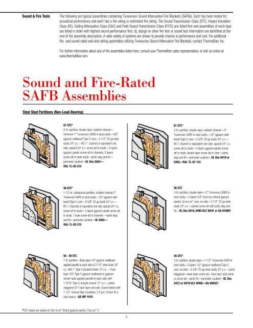
<strong>Sound</strong> & <strong>Fire</strong> Tests The following are typical assemblies containing THERMAFIBER <strong>Sound</strong> Attenuation <strong>Fire</strong> Blankets (<strong>SAFB</strong>s). Each has been tested for<br />
acoustical performance <strong>and</strong> each has a fire rating or estimated fire rating. The <strong>Sound</strong> Transmission Class (STC), Impact Insulation<br />
Class (IIC), Ceiling Attenuation Class (CAC) <strong>and</strong> Field <strong>Sound</strong> Transmission Class (FSTC) are listed first <strong>and</strong> assemblies of each type<br />
are listed in order with highest sound performance first. UL design or other fire test or sound test information are identified at the<br />
end of the assembly description. A wide variety of systems are shown to provide choices in performance <strong>and</strong> cost. For additional<br />
fire- <strong>and</strong> sound-rated wall <strong>and</strong> ceiling assemblies utilizing THERMAFIBER <strong>Sound</strong> Attenuation <strong>Fire</strong> Blankets, contact Thermafiber, Inc.<br />
Steel Stud Partitions (Non-Load-Bearing)<br />
For further information about any of the assemblies listed here, consult your Thermafiber sales representative, or visit us online at<br />
www.thermafiber.com.<br />
<strong>Sound</strong> <strong>and</strong> <strong>Fire</strong>-<strong>Rated</strong><br />
<strong>SAFB</strong> <strong>Assemblies</strong><br />
A-17<br />
WP 1015<br />
A-25<br />
61 STC*<br />
2-hr. partition, double-layer, resilient channel—<br />
minimum 1" THERMAFIBER <strong>SAFB</strong> in stud cavity—5/8"<br />
gypsum wallboard Type C core—2-1/2" 25 ga steel<br />
studs 24" o.c.—RC-1 channel or equivalent one<br />
side, spaced 24" o.c. screw-att to studs—2 layers<br />
gypsum panels screw-att to channels, 2 layers<br />
screw-att to steel studs—joints stag <strong>and</strong> fin—<br />
perimeter caulked—UL Des U454—<br />
RAL-TL-83-214<br />
58 STC*<br />
1-1/2-hr. unbalanced partition, resilient channel 3"<br />
THERMAFIBER <strong>SAFB</strong> in stud cavity—1/2" gypsum wallboard<br />
Type C core—3-5/8" 20 ga studs 24" o.c.—<br />
RC-1 channels or equivalent one side spaced 24" o.c.<br />
screw-att to studs—2 layers gypsum panels screw-att<br />
to studs, 1 layer screw-att to channels —joints stag<br />
<strong>and</strong> fin—perimeter caulked—UL U452—<br />
RAL-TL-83-215<br />
55 - 59 STC<br />
1-hr. partition—Base layer 1/4” gypsum wallboard<br />
applied parallel to each side of 2-1/2” steel studs 24”<br />
o.c. with 1” Type S drywall screws 12” o.c. —Face<br />
layer 5/8” Type X gypsum wallboard or gypsum<br />
veneer base applied parallel to each side with<br />
1-5/16” Type S drywall screws 12” o.c.—Joints<br />
staggered 24” each layer <strong>and</strong> side. <strong>Sound</strong> tested with<br />
1-1/2” mineral fiber insulation, 3.0 pcf, friction fit in<br />
stud space—GA WP-1015<br />
*STC values are based on SHEETROCK ® Br<strong>and</strong> gypsum panels, FIRECODE ® C<br />
5<br />
A-28<br />
A-31<br />
A-19<br />
61 STC*<br />
3-hr. partition, double-layer, resilient channel—3"<br />
THERMAFIBER <strong>SAFB</strong> in stud cavity—1/2" gypsum wallboard<br />
Type C core—3-5/8" 20 ga studs 24" o.c.—<br />
RC-1 channel or equivalent one side, spaced 24" o.c.<br />
screw-att to studs—3 layers gypsum panels screwatt<br />
to studs, double layer screw-att to chan—joints<br />
stag <strong>and</strong> fin—perimeter caulked—UL Des U419 or<br />
U455—RAL-TL-87-153<br />
56 STC<br />
4-hr. partition, double-layer—2" THERMAFIBER <strong>SAFB</strong> in<br />
stud cavity—2 layers 3/4" SHEETROCK Br<strong>and</strong> gypsum<br />
panels, ULTRACODE ® core, ea side—2-1/2" 25 ga steel<br />
studs 24" o.c.—panels screw att with joints stag <strong>and</strong><br />
fin—UL Des U419, U490-ULC W441 or SA-910907<br />
55 STC*<br />
2-hr. partition, double-layer—1-1/2" THERMAFIBER <strong>SAFB</strong> in<br />
stud cavity—2 layers 1/2" gypsum wallboard Type C<br />
core, ea side—3-5/8" 25 ga steel studs 24" o.c.—joints<br />
staggered—base layer screw att—face layer strip lamin<br />
or screw att—joints fin—perimeter caulked—UL Des<br />
U412 or U419-ULC W406—SA-800421
A-14<br />
A-23<br />
Steel Stud Partitions (Non-Load-Bearing) continued<br />
WP 1530<br />
54 STC*<br />
1-hr. partition, single-layer, resilient channel—<br />
3 THERMAFIBER <strong>SAFB</strong> in stud cavity—5/8 gypsum<br />
wallboard Type C core—3-5/8 20 ga steel studs<br />
24 o.c.—RC-1 chan or equivalent one side spaced<br />
24o.c. screw-att to studs—gypsum panels screwatt<br />
to studs & RC-1 channels—joints stag <strong>and</strong> fin—<br />
perimeter caulked—UL Des U419 or U451 rating<br />
also applies with IMPERIAL Br<strong>and</strong> gypsum base,<br />
FIRECODE C core, <strong>and</strong> veneer finish surface—<br />
RAL-TL-83-216<br />
50 - 54 FSTC<br />
2-hr. partition—Base layer 1/2” Type X gypsum wallboard<br />
or gypsum veneer base applied parallel to each<br />
side of 1-5/8” steel studs 24” o.c. with 1” Type S drywall<br />
screws 12” o.c.—Face layer 1/2” Type X gypsum<br />
wallboard or gypsum veneer base applied parallel to<br />
each side with 1-5/8” Type S drywall screws 12”<br />
o.c.—Joints staggered 24” each layer <strong>and</strong> side. <strong>Sound</strong><br />
tested with 1-1/2” mineral fiber insulation friction fit in<br />
stud space—GA WP-1530<br />
Note: Can be used as a non-load bearing area separation<br />
wall—GA ASW-1100<br />
50 STC<br />
2-hr. partition, single-layer—3 THERMAFIBER <strong>SAFB</strong> in<br />
stud cavity—3/4 SHEETROCK Br<strong>and</strong> gypsum Panels,<br />
ULTRACODE core, ea side—min. 3-1/2 25 ga steel<br />
studs 24 o.c.—panels screw att—joints stag &<br />
fin—perimeter caulked—UL Des U419, U491 or<br />
ULC W440—USG-910617<br />
*STC values are based on SHEETROCK ® Br<strong>and</strong> gypsum panels, FIRECODE ® C<br />
**STC values are based on SHEETROCK ® Br<strong>and</strong> gypsum panels, FIRECODE ®<br />
6<br />
A-1<br />
WP 1545<br />
WP 1070<br />
51 STC**<br />
1-hr. partition, single-layer, Creased—3" Creased<br />
THERMAFIBER <strong>SAFB</strong> in stud cavity—5/8" gypsum wallboard<br />
Type X—3-5/8" 25 ga steel studs 24" o.c.—<br />
panels screw att—joints stag & fin—perimeter<br />
caulked—UL Des U419 or U465—RAL-TL-90-<br />
166—SA-860620<br />
50 - 54 STC<br />
2-hr. partition—Base layer 1/2” Type X gypsum<br />
wallboard or gypsum veneer base applied parallel to<br />
each side of 2-1/2” steel studs 24” o.c. with 1” Type S<br />
drywall screws 24” o.c.—Face layer 1/2” Type X gypsum<br />
wallboard or gypsum veneer base applied<br />
parallel to each side with 1-5/8” Type S drywall screws<br />
12” o.c.—Joints staggered 24” each layer <strong>and</strong> side.<br />
<strong>Sound</strong> tested with 1-1/2” mineral fiber insulation<br />
friction fit in stud space—GA WP-1545<br />
Note: Can be used as a non-load bearing area<br />
separation wall—GA ASW-1105<br />
45 - 49 STC<br />
1-hr. partition—One layer 1/2” Type X gypsum<br />
wallboard or gypsum veneer base applied parallel to<br />
each side of 2-1/2” steel studs 24” o.c. with 1” Type S<br />
drywall screws 8” o.c. at vertical joints <strong>and</strong> 12” o.c. at<br />
intermediate studs. 2” mineral fiber insulation, 2.5 pcf,<br />
friction fit in stud space—Joints staggered 24” on<br />
opposite sides—GA WP-1070
A-71<br />
Steel Stud Chase Walls (Non-Load Bearing)<br />
A-46<br />
Shaft Wall Systems (Non-Load Bearing)<br />
A-53<br />
Area Separation Walls (Non-Load Bearing)<br />
A-64<br />
Demountable Partitions (Non-Load Bearing)<br />
57 STC**<br />
2-hr. partition, double-layer chase wall—3-1/2"<br />
THERMAFIBER <strong>SAFB</strong> on one side in stud cavity—<br />
2 layers 5/8" gypsum wallboard Type X ,ea side—<br />
1-5/8" 25 ga steel studs 24" o.c. in 2 rows spaced<br />
6-1/4" apart—5/8" gypsum panel gussets or steel<br />
run braces spanning chase screw-att to studs—<br />
panels appl screw att—joints stag & fin—UL Des<br />
U420—TL-76-156<br />
52 STC***<br />
2-hr. shaft wall partition—3" THERMAFIBER <strong>SAFB</strong><br />
in stud cavity—1" gypsum wallboard liner panels, set<br />
between 4" steel C-H studs 24" o.c. one side—3/4"<br />
SHEETROCK Br<strong>and</strong> gypsum panels, ULTRACODE Core,<br />
other side—panels screw att—joints stag & fin—<br />
perimeter caulked—UL Des U415 or U492, ULC<br />
W508—SA-910913<br />
60 STC***<br />
2-hr. area separation wall partition—3" THERMAFIBER<br />
<strong>SAFB</strong> on both sides in stud cavities—1/2" gypsum<br />
wallboard—two 1" gypsum wallboard liner panels set<br />
between one-piece steel H studs 24" o.c.—2 x 4<br />
wood studs 16" o.c. each side on 2 x 4 plates min.<br />
3/4" from liner panels—gypsum panels att with 1-<br />
1/4" Type W screws 12" o.c.—joints stag & fin—<br />
perimeter caulked—UL Des U336—TL-88-350<br />
47 STC<br />
1-hr. demountable partition (ULTRAWALL ® Partition)—<br />
1" THERMAFIBER <strong>SAFB</strong> in stud cavity—concealed “H”<br />
studs 24" or 30" o.c.—3/4" x 24" or 30" bevel edge<br />
ULTRAWALL ® gypsum panels—joints unfin—perim<br />
gaskets—based on 24" panels—U of C 8-18-67—<br />
based on 30" panels—U of C 7-23-69—BBN-<br />
701216<br />
*STC values are based on SHEETROCK ® Br<strong>and</strong> gypsum panels, FIRECODE ® C<br />
**STC values are based on SHEETROCK ® Br<strong>and</strong> gypsum panels, FIRECODE ®<br />
***STC values are based on SHEETROCK ® Br<strong>and</strong> gypsum liner panels<br />
7<br />
A-43<br />
A-54<br />
For more area separation wall designs see page 6:<br />
GA WP-1530 (ref: GA ASW-1100)<br />
GA WP-1545 (ref: GA ASW-1105)<br />
52 STC**<br />
1-hr. partition, single-layer chase wall—3-1/2"<br />
THERMAFIBER <strong>SAFB</strong> on one side in stud cavity—5/8"<br />
gypsum wallboard Type X, ea side—1-5/8" 25 ga<br />
steel studs 24" o.c. in 2 rows spaced 6-1/4" apart—<br />
5/8" gypsum panel gussets or steel run braces spanning<br />
chase screw-att to studs—panels screw att—<br />
joints stag & fin—UL Des U420—TL-76-155<br />
47 STC* <strong>and</strong> ***<br />
2-hr. shaft wall partition—1" THERMAFIBER <strong>SAFB</strong> in<br />
stud cavity—2 layers 1/2" gypsum wallboard Type C<br />
core, one side—1" gypsum wallboard liner panels<br />
set between 25 ga. steel C-H studs 24" o.c.—joints<br />
fin—UL Des U415 or U438—BBN-750706
A-84<br />
A-102<br />
A-100<br />
Cement Board Partitions (Non-Load Bearing)<br />
Wood Stud Partitions (Load Bearing)<br />
Double Wood Stud Chase Wall<br />
WP 5510<br />
56 STC* <strong>and</strong> ****<br />
2-hr. partition—double-layer—3 THERMAFIBER <strong>SAFB</strong><br />
in stud cavity—2 layer—1/2 Cemetitious Backer<br />
Board (cement board) <strong>and</strong> 1/4 ceramic tile—base<br />
layer 1/2 gypsum wallboard Type C core one side—<br />
2 layers 1/2 gypsum wallboard Type C core other<br />
side—3-5/8 25 ga steel studs 16 o.c.—cement<br />
board att with 1-5/8 Type S-12 corrosion resistant<br />
wafer-head steel screws—joints taped—UL Des<br />
U443—SA-851016<br />
59 STC*<br />
2-hr. partition—double-layer, resilient channel—<br />
2 THERMAFIBER <strong>SAFB</strong> in stud cavity—2 layers 5/8<br />
gypsum wallboard Type C core, each side—2 x 4<br />
16 o.c.—RC-1 channel or equivalent one side,<br />
spaced 24 o.c.—resilient side screw att—opp side<br />
nail att—both base layers appl vert <strong>and</strong> face layers<br />
appl horiz—resilient layers perimeter caulked—joints<br />
fin—UL Des U334—TL-67-239<br />
50 STC*<br />
1-hr. partition—single-layer, resilient channel—<br />
3 THERMAFIBER <strong>SAFB</strong> in stud cavity—5/8 gypsum<br />
wallboard Type C core—2 x 4 16 or 24 o.c.—RC-<br />
1 channel or equivalent one side, spaced 24 o.c.—<br />
panels app horiz & att to channels—end joints backblocked<br />
with RC-1 channel with 1 TYPE S screws—<br />
opp side direct att with 1-1/4 Type W screws—<br />
joints fin—perimeter caulked—UL Des U311 <strong>and</strong><br />
ULC U311—BBN-760903<br />
55 - 59 STC<br />
1-hr. partition—Base layer 1/4” gypsum wallboard<br />
applied parallel to each side of double row of 2 x 4<br />
wood studs 16” o.c. on separate plates spaced 1-1/2”<br />
apart with 4d coated nails, 1-1/2” long, 0.099” shank,<br />
1/4” heads, 12” o.c. Joints staggered 16” on opposite<br />
sides.—Face layer 1/2” Type X plain or predecorated<br />
gypsum wallboard or gypsum veneer base applied parallel<br />
to each side with 3/8” beads of adhesive 16” o.c.<br />
<strong>and</strong> 5d coated nails, 1-3/4” long, 0.099” shank, 1/4”<br />
heads, 16” o.c. at top <strong>and</strong> bottom plates. 4d finish<br />
nails, 1-1/2” long, 0.072” shank, 0.1055” heads, driven<br />
at a 45 0 angle 16” o.c. horizontally <strong>and</strong> 24” o.c.<br />
vertically. Joints offset 24” from base layer joints.—<br />
<strong>Sound</strong> tested with 1-1/2” mineral fiber insulation in<br />
stud space. Horizontal bracing required at mid height.<br />
(Load-Bearing)—WP 5510<br />
8<br />
A-81<br />
A-97<br />
A-108<br />
50 STC* <strong>and</strong> ****<br />
1-hr. partition—single-layer—3" THERMAFIBER <strong>SAFB</strong> in<br />
stud cavity—1/2" Cemetitious Backer Board (cement<br />
board) <strong>and</strong> 1/4" ceramic tile one side—5/8" gypsum<br />
wallboard Type C, one side—3-5/8" 20 ga steel<br />
studs 16 o.c.—cement board att with 1-1/4 Type<br />
S-12 corrosion resistant wafer-head steel screws—<br />
joint taped—UL Des U442, ULC W419 or W423—<br />
SA-840313<br />
46 STC**<br />
1-hr. partition—single-layer—3 THERMAFIBER <strong>SAFB</strong><br />
in stud cavity—5/8 gypsum wallboard Type X, or<br />
gypsum wallboard, water-resistant, Type X—2 x 4<br />
24 o.c.—panels nailed 7 o.c.—1-7/8 cem ctd<br />
nails—joints exp or fin—perim caulked—UL Des<br />
U305 <strong>and</strong> UL Des U314—BBN-700725<br />
54 STC**<br />
1-hr. chase wall partition—single-layer—<br />
3 THERMAFIBER <strong>SAFB</strong> on one side in stud cavity—<br />
5/8 gypsum wallboard Type X—2 x 3 non-loadbearing<br />
studs 16 o.c.—2 x 3 plates 1 apart—<br />
panels screwed or nailed 7 o.c.—joints fin—perim<br />
caulked—est. fire rating based on UL Des U305<br />
<strong>and</strong> UL Des U340—TL-77-149 (Non-load bearing)<br />
*STC values are based on SHEETROCK ® Br<strong>and</strong> gypsum panels, FIRECODE ® C<br />
**STC values are based on SHEETROCK ® Br<strong>and</strong> gypsum panels, FIRECODE ®<br />
****STC values are based on DUROCK ® Br<strong>and</strong> cement board panels
Cement Board/Wood Stud Partitions (Load Bearing)<br />
A-114<br />
40 STC* <strong>and</strong> ****<br />
1-hr. partition—single-layer—3-1/2" THERMAFIBER<br />
<strong>SAFB</strong> in stud cavity—1/2" Cemetitious Backer Board<br />
(cement board) <strong>and</strong> 1/4" ceramic tile one side—2 x<br />
4 studs 16" o.c.—board att with 1-5/8" TYPE S-12<br />
corrosion resistant wafer-head steel screws or 1-1/2"<br />
hot-dipped galv nails 8" o.c.—5/8" gypsum wallboard<br />
Type C core other side—joints taped—UL Des<br />
U329—USG-840314<br />
Wood Joist Ceiling Systems (Unrestrained <strong>Assemblies</strong>)<br />
Mineral Fiber Overlay on Acoustical Ceiling System<br />
B-92<br />
B-50<br />
B-45<br />
59 STC/69 IIC*<br />
2-hr. ceiling—double-layer—3"<br />
THERMAFIBER <strong>SAFB</strong>—floor of carpet/pad,<br />
1-1/2" flooring, 1/2" plywood—2 x 10<br />
wd joists 16" o.c.—ceiling of 2 layers<br />
5/8" gypsum wallboard Type C core,<br />
over RC-1 channels or equivalent 16"<br />
o.c.—UL Des L541—RAL-TL-90-<br />
40/RAL-IN-90-5<br />
47 STC/40 IIC*<br />
1-hr. ceiling—single-layer—<br />
1" FIRESPAN 90 laid over furring channels<br />
below joists—1/2" gypsum wallboard<br />
Type C core, ceiling— 3/4" T&G<br />
plywd—I-shaped wd joist 24" o.c.—<br />
met fur chan 24" o.c. clip-att to joist—<br />
panels screw att to chan 12" o.c.—<br />
joints fin—UL Des L530 based on TJI ®<br />
joists—TL-81-87—IN-81-16<br />
48 CAC<br />
Class A ceiling—3" THERMAFIBER <strong>SAFB</strong><br />
laid over ceiling, extending 4’ each side<br />
of partition—AURATONE ® 5/8" x 24" x<br />
48" acoust clg panels in Susp Exp Grid<br />
Syst—contin over partn—ASTM<br />
E84—<strong>Sound</strong> test USG-820406<br />
*STC values are based on SHEETROCK ® Br<strong>and</strong> gypsum panels, FIRECODE ® C<br />
****STC values are based on DUROCK ® Br<strong>and</strong> cement board panels<br />
9<br />
B-36<br />
51 STC/46 IIC*<br />
1-hr. ceiling—single-layer, resilient<br />
channel—3 THERMAFIBER <strong>SAFB</strong> between<br />
joists—1/2 gypsum wallboard Type C<br />
core—1-1/4 nom wd sub & fin flr—2<br />
x 10 wd joist 16 o.c.—RC-1 channel<br />
or equivalent att to joists—panels att<br />
with 1 TYPE S screws—joints fin—est<br />
fire rating based on—UL Des L514—<br />
CK-6512-9