BG-12 Series Manual Pull Stations - Fire-Lite Alarms
BG-12 Series Manual Pull Stations - Fire-Lite Alarms
BG-12 Series Manual Pull Stations - Fire-Lite Alarms

Create successful ePaper yourself
Turn your PDF publications into a flip-book with our unique Google optimized e-Paper software.
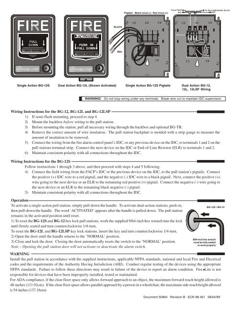
Single Action <strong>BG</strong>-<strong>12</strong>S<br />
‘Pigtails’ Black in/out (-) Red in\out (+)<br />
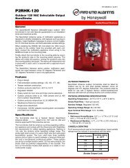
Wiring Instructions for the <strong>BG</strong>-<strong>12</strong>, <strong>BG</strong>-<strong>12</strong>L and <strong>BG</strong>-<strong>12</strong>LSP<br />
1) If semi-flush mounting, proceed to step 4.<br />
2) Mount the backbox before wiring to the pull station.<br />
3) Before mounting the station, pull all necessary wiring through the backbox and optional <strong>BG</strong>-TR.<br />
4) Remove the correct amount of wire insulation. The pull station backplate is molded with a strip gauge to measure the<br />
amount of insulation to be removed.<br />
5) Connect the wiring from the fire alarm control panel’s IDC, or any previous device on the IDC, to terminals 1 and 2 on the<br />
pull stations terminal strip. Connect the next device on the IDC or End-of-Line Resistor (ELR) to terminals 1 and 2.<br />
6) Maintain consistent polarity with all connections throughout the IDC.<br />
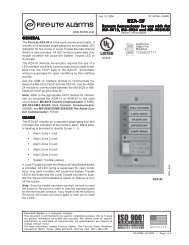
Wiring Instructions for the <strong>BG</strong>-<strong>12</strong>S<br />
Follow instructions 1 through 3 above, and then proceed with steps 4 and 5 following:<br />
4) Connect the field wiring from the FACP’s IDC or the previous device on the IDC, to the pull station’s pigtails. Connect<br />
the positive (+) IDC wire to a red pigtail, and the negative (-) IDC wire to a black pigtail. Next, connect the positive (+)<br />
wire going to the next device or an ELR to the remaining red positive (+) pigtail. Connect the negative (-) wire going to<br />
the next device or an ELR to the remaining black negative (-) pigtail.<br />
5) Maintain consistent polarity with all connections throughout the IDC.<br />
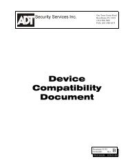
STRIP GAUGE<br />
Dual Action <strong>BG</strong>-<strong>12</strong>L (Shown Activated) Single Action <strong>BG</strong>-<strong>12</strong>S Pigtails<br />
Operation<br />
To activate a single-action pull station, simply pull-down the handle. To activate dual-action stations, push-in,<br />
then pull-down the handle. The word ‘ACTIVATED’ appears after the handle is pulled down. The pull station<br />
remains in the activated position until reset.<br />
1) To reset the <strong>BG</strong>-<strong>12</strong>S and <strong>BG</strong>-<strong>12</strong> hex lock pull stations, work the supplied 9/64-inch hex wrench into the lock<br />
until firmly seated and turn counterclockwise 1/4-turn.<br />
To reset the <strong>BG</strong>-<strong>12</strong>L and <strong>BG</strong>-<strong>12</strong>LSP key lock stations, insert the key and turn counterclockwise 1/4-turn.<br />
2) Open the door until the handle returns to the ‘NORMAL’ position.<br />
3) Close and lock the door. Closing the door automatically resets the switch to the ‘NORMAL’ position.<br />
Note – Opening the pull station door will not activate or deactivate the alarm switch.<br />
BLACK<br />
WARNING<br />
Install the pull station in accordance with the supplied instructions, applicable NFPA standards, national and local <strong>Fire</strong> and Electrical<br />
codes and the requirements of the Authority Having Jurisdiction (AHJ). Conduct regular testing of the devices using the appropriate<br />
NFPA standards. Failure to follow these directions may result in failure of the device to report an alarm condition. <strong>Fire</strong> <strong>Lite</strong> is not<br />
responsible for devices that have been improperly installed, tested or maintained.<br />
For ADA compliance, if the clear floor space only allows forward approach to an object, the maximum forward reach height allowed is<br />
48-inches (<strong>12</strong>1.92cm). If the clear floor space allows parallel approach by a person in a wheelchair, the maximum side reach height allowed<br />
is 54-inches (137.16cm).<br />
RED<br />
✵✳ ✰✡✴ ✔✔✔✐✙✙✑<br />
<strong>12</strong>3456<br />
From FACP To Next Addresable Device<br />
<strong>12</strong>3456<br />
IDC IDC<br />
<strong>12</strong>3456<br />
STRIP GAUGE<br />
Dual Action <strong>BG</strong>-<strong>12</strong>,<br />
<strong>12</strong>L, <strong>12</strong>LSP Wiring<br />
WARNING! Do not loop wiring under any terminals. Break wire run to maintain IDC supervision.<br />
<strong>BG</strong>-<strong>12</strong>S / <strong>BG</strong>-<strong>12</strong><br />
9/64-inch hex wrench<br />
must be fully seated<br />
to work properly<br />
Document 50964 Revision B ECN 98-461 08/04/99<br />
✵ ✳ ✰✡ ✴ ✔✔✔✐✙✙✑