BG-12 Series Manual Pull Stations - Fire-Lite Alarms
BG-12 Series Manual Pull Stations - Fire-Lite Alarms
BG-12 Series Manual Pull Stations - Fire-Lite Alarms

You also want an ePaper? Increase the reach of your titles
YUMPU automatically turns print PDFs into web optimized ePapers that Google loves.
Dual Action <strong>BG</strong>-<strong>12</strong>L<br />
<strong>BG</strong>-<strong>12</strong> <strong>Series</strong> <strong>Manual</strong> <strong>Pull</strong> <strong>Stations</strong><br />
Document: 50964 Revision: B ECN: 98-461 08/04/99<br />
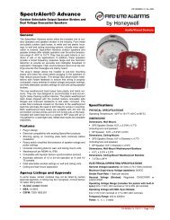
Description<br />
The <strong>BG</strong>-<strong>12</strong> <strong>Series</strong> <strong>Pull</strong> <strong>Stations</strong> are non-coded manual pull<br />
stations which provide a <strong>Fire</strong> Alarm Control Panel (FACP)<br />
with a single alarm initiating input signal. The <strong>BG</strong>-<strong>12</strong> series<br />
includes both single-action and dual-action models equipped<br />
with either a hex or key lock / reset. A single-action pullstation<br />
is activated by a single pull-down of the alarm handle.<br />
The dual-action versions require pushing in the handle, then<br />
pulling the handle down for activation. The <strong>BG</strong>-<strong>12</strong> series<br />
manual pull stations are UL listed and meet the ADA requirement<br />
of a 5-lb. maximum pull force to activate. Operating<br />
instructions are molded into the handle along with Braille<br />
text. Molded terminal numbers can be found adjacent to the<br />
wiring terminals.<br />
<strong>BG</strong>-<strong>12</strong> <strong>Series</strong> Models available:<br />
<strong>BG</strong>-<strong>12</strong>S – Single action with ‘pigtail’ connections and a hex<br />
lock reset. Pigtail wires are provided for connection to the<br />
FACP Initiating Device Circuit (IDC).<br />
<strong>BG</strong>-<strong>12</strong> – Dual action model with screw terminal connections<br />
and a hex lock reset.<br />
<strong>BG</strong>-<strong>12</strong>L – Same as <strong>BG</strong>-<strong>12</strong> except with a key lock reset.<br />
<strong>BG</strong>-<strong>12</strong>LSP – Same as <strong>BG</strong>-<strong>12</strong>L except with both English and<br />
Spanish operating instructions.<br />
Switch Contact Rating<br />
All switch contacts are rated for 0.25 A at 30 volts (AC or DC).<br />
Installation<br />
Surface mount the <strong>BG</strong>-<strong>12</strong> pull station to a SB-10 surface backbox.<br />
Semi-flush mount the <strong>BG</strong>-<strong>12</strong> to a standard single gang, double-gang,<br />
or 4-inch (10.16cm) square electrical box. Mount the optional Trim<br />
Ring (<strong>BG</strong>-TR) if necessary when semi-flush mounting the unit.<br />
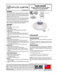
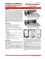
The word ‘ACTIVATED’<br />
is displayed<br />
on the pull station’s<br />
pulled-down handle<br />
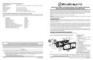
If, during mounting of the pull station, the door becomes detached,<br />
complete the following steps to reattach the door to the<br />
backplate. The door cannot be connected to the pull station if the<br />
unit is mounted to the backbox.<br />
1. Position the door and backplate side by side in the full open<br />
position. (i.e. 180-degrees with respect to each other.)<br />
2. With the backplate position fixed, move the door behind the<br />
backplate, as shown in the illustration below, part A.<br />
3. Align the hinge posts and holes by bringing the door up to meet<br />
the backplate, paying particular attention to the ‘keying’ that<br />
occurs when the door’s post hole is aligned to the backplate’s<br />
hinge post. Refer to the illustration, part B.<br />
4. With the two pieces aligned and ‘keyed’ together, slide the holes<br />
down onto the posts. Refer to the illustration, part C.<br />
5. Holding the backplate, close the door slightly to lock the door<br />
and backplate together.<br />
DOOR KEYS INTO<br />
B AC K PLATE AT TH IS PO IN T<br />
POST<br />
C<br />
13<br />
<strong>12</strong><br />
11<br />
10<br />
14<br />
9<br />
P/ N 5099 7 REV.<br />
REFER TO D OCU MENT<br />
NUMB ER 51 015 RE V.<br />
B<br />
A<br />
HOLE<br />
POST<br />
HOLE<br />
POST<br />
LOOP ADDRESS<br />
DOOR MATED TO BACKPLATE<br />
DOOR ATTACHMENT<br />
With the door and<br />
backplate aligned and<br />
‘keyed’ together, slide<br />
the holes down onto<br />
the posts.<br />
13<br />
<strong>12</strong><br />
11<br />
10<br />
P/N 509 97 REV.<br />
REFER TO DOCUMENT<br />
NUMBER 51015 RE V.<br />
LOOP A DDR ESS<br />
Closing the door slightly<br />
locks the door and<br />
backplate together.
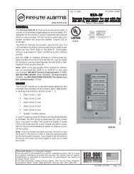
Single Action <strong>BG</strong>-<strong>12</strong>S<br />
‘Pigtails’ Black in/out (-) Red in\out (+)<br />
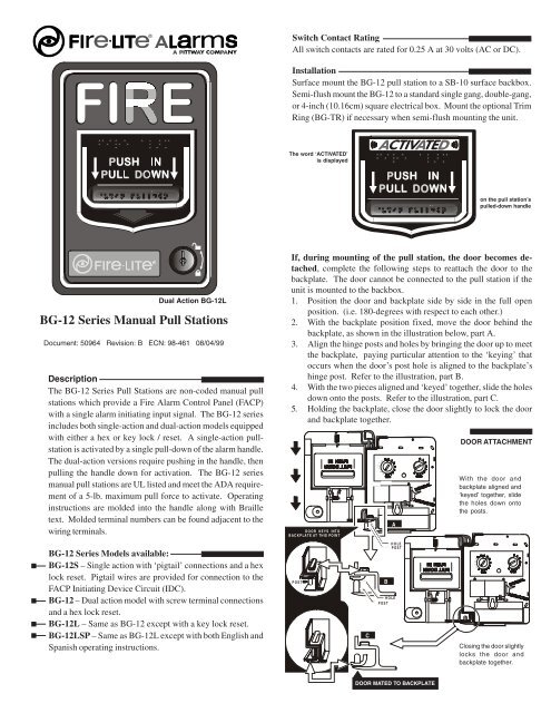
Wiring Instructions for the <strong>BG</strong>-<strong>12</strong>, <strong>BG</strong>-<strong>12</strong>L and <strong>BG</strong>-<strong>12</strong>LSP<br />
1) If semi-flush mounting, proceed to step 4.<br />
2) Mount the backbox before wiring to the pull station.<br />
3) Before mounting the station, pull all necessary wiring through the backbox and optional <strong>BG</strong>-TR.<br />
4) Remove the correct amount of wire insulation. The pull station backplate is molded with a strip gauge to measure the<br />
amount of insulation to be removed.<br />
5) Connect the wiring from the fire alarm control panel’s IDC, or any previous device on the IDC, to terminals 1 and 2 on the<br />
pull stations terminal strip. Connect the next device on the IDC or End-of-Line Resistor (ELR) to terminals 1 and 2.<br />
6) Maintain consistent polarity with all connections throughout the IDC.<br />
Wiring Instructions for the <strong>BG</strong>-<strong>12</strong>S<br />
Follow instructions 1 through 3 above, and then proceed with steps 4 and 5 following:<br />
4) Connect the field wiring from the FACP’s IDC or the previous device on the IDC, to the pull station’s pigtails. Connect<br />
the positive (+) IDC wire to a red pigtail, and the negative (-) IDC wire to a black pigtail. Next, connect the positive (+)<br />
wire going to the next device or an ELR to the remaining red positive (+) pigtail. Connect the negative (-) wire going to<br />
the next device or an ELR to the remaining black negative (-) pigtail.<br />
5) Maintain consistent polarity with all connections throughout the IDC.<br />
STRIP GAUGE<br />
Dual Action <strong>BG</strong>-<strong>12</strong>L (Shown Activated) Single Action <strong>BG</strong>-<strong>12</strong>S Pigtails<br />
Operation<br />
To activate a single-action pull station, simply pull-down the handle. To activate dual-action stations, push-in,<br />
then pull-down the handle. The word ‘ACTIVATED’ appears after the handle is pulled down. The pull station<br />
remains in the activated position until reset.<br />
1) To reset the <strong>BG</strong>-<strong>12</strong>S and <strong>BG</strong>-<strong>12</strong> hex lock pull stations, work the supplied 9/64-inch hex wrench into the lock<br />
until firmly seated and turn counterclockwise 1/4-turn.<br />
To reset the <strong>BG</strong>-<strong>12</strong>L and <strong>BG</strong>-<strong>12</strong>LSP key lock stations, insert the key and turn counterclockwise 1/4-turn.<br />
2) Open the door until the handle returns to the ‘NORMAL’ position.<br />
3) Close and lock the door. Closing the door automatically resets the switch to the ‘NORMAL’ position.<br />
Note – Opening the pull station door will not activate or deactivate the alarm switch.<br />
BLACK<br />
WARNING<br />
Install the pull station in accordance with the supplied instructions, applicable NFPA standards, national and local <strong>Fire</strong> and Electrical<br />
codes and the requirements of the Authority Having Jurisdiction (AHJ). Conduct regular testing of the devices using the appropriate<br />
NFPA standards. Failure to follow these directions may result in failure of the device to report an alarm condition. <strong>Fire</strong> <strong>Lite</strong> is not<br />
responsible for devices that have been improperly installed, tested or maintained.<br />
For ADA compliance, if the clear floor space only allows forward approach to an object, the maximum forward reach height allowed is<br />
48-inches (<strong>12</strong>1.92cm). If the clear floor space allows parallel approach by a person in a wheelchair, the maximum side reach height allowed<br />
is 54-inches (137.16cm).<br />
RED<br />
✵✳ ✰✡✴ ✔✔✔✐✙✙✑<br />
<strong>12</strong>3456<br />
From FACP To Next Addresable Device<br />
<strong>12</strong>3456<br />
IDC IDC<br />
<strong>12</strong>3456<br />
STRIP GAUGE<br />
Dual Action <strong>BG</strong>-<strong>12</strong>,<br />
<strong>12</strong>L, <strong>12</strong>LSP Wiring<br />
WARNING! Do not loop wiring under any terminals. Break wire run to maintain IDC supervision.<br />
<strong>BG</strong>-<strong>12</strong>S / <strong>BG</strong>-<strong>12</strong><br />
9/64-inch hex wrench<br />
must be fully seated<br />
to work properly<br />
Document 50964 Revision B ECN 98-461 08/04/99<br />
✵ ✳ ✰✡ ✴ ✔✔✔✐✙✙✑
<strong>BG</strong>-<strong>12</strong>L de Doble Acción<br />
Estaciones Pulsadoras <strong>Manual</strong>es de la<br />
Serie <strong>BG</strong>-<strong>12</strong><br />
Documento: 50964 Revisión: B ECN: 98-461 08/04/99<br />
Descripción<br />
Las Estaciones Pulsadoras de la Serie <strong>BG</strong>-<strong>12</strong> son estaciones manuales<br />
no codificadas cuales proporcionan a un Panel de Control de Alarma<br />
contra Incendios (FACP) con una señal de entrada de iniciación de<br />
alarma. La serie <strong>BG</strong>-<strong>12</strong> incluye los modelos de acción singular y<br />
acción doble equipados con un rearme por cerradura de llave o<br />
cerradura de llave hexagonal. Una estación de acción singular es<br />
activada halando el manubrio. Primero empujando el manubrio de<br />
alarma y luego bajandolo, activa a la estación de doble acción. Las<br />
estaciones pulsadoras de la serie <strong>BG</strong>-<strong>12</strong> son reconocidas por UL y<br />
llenan los requisitos de ADA de una fuerza de hale máxima de 5-lb.<br />
para activarla. Las instrucciones están moldeadas en el manubrio.<br />
Los números de terminal moldeados pueden ser encontrados adjunto<br />
a los terminales de alambrado.<br />
Modelos disponibles de la Serie <strong>BG</strong>-<strong>12</strong>:<br />
<strong>BG</strong>-<strong>12</strong>S – Acción singular con conexiones de cable flexible y un<br />
rearme de cerradura hexagonal. Los cables flexibles son<br />
proporcionados para la conexión al Circuito del Dispositivo de<br />
Iniciación (IDC) del FACP.<br />
<strong>BG</strong>-<strong>12</strong> – Modelo de doble acción con conexiones de terminal y<br />
rearme por cerradura hexagonal.<br />
<strong>BG</strong>-<strong>12</strong>L – Igual a la <strong>BG</strong>-<strong>12</strong> pero con rearme por cerradura de llaves.<br />
<strong>BG</strong>-<strong>12</strong>LSP – Igual a la <strong>BG</strong>-<strong>12</strong>L pero con instrucciones de<br />
funcionamiento en Inglés y Español.<br />
Parámetros de Contacto del Interruptor<br />
Todos los contactos de interruptor son clasificados para 0.25 A en 30<br />
voltios (AC o DC).<br />
Instalación<br />
Instale en la superficie la estación <strong>BG</strong>-<strong>12</strong> a una caja posterior de superficie<br />
SB-10. Instale semi empotrada la <strong>BG</strong>-<strong>12</strong> a una caja eléctrica cuadrada de 4pulgadas<br />
(10.16cm) de grupo doble o singular. Instale el Anillo Embellecedor<br />
(<strong>BG</strong>-TR) si es necesario cuando la unidad está siendo semi-empotrada.<br />
La palabra ‘ACTIVATED’<br />
es mostrada<br />
B<br />
Si , mientrás se instalando la estación, la puerta se separa, complete<br />
los siguientes pasos para unir la puerta a la placa posterior. La puerta no<br />
puede ser conectada a la estación pulsadora si la unidad está instalada en la<br />
caja posterior.<br />
1. Coloque la puerta y la placa posterior de lado a lado en la posición de<br />
abierto completo. (es decir 180-grados con respecto la una a la otra.)<br />
2. Con la placa posterior fijada en lugar, mueva la puerta detrás de la placa<br />
posterior, como es mostrado en el dibujo debajo, parte A.<br />
3. Alínee los postes y orificios de la bisagra juntando la puerta con la placa<br />
posterior, poniendo atención a como las piezas caen en su lugar cuando<br />
los orificos de la puerta son alineados con los postes de la bisagra de la<br />
placa posterior. Refiérase al dibujo, parte B.<br />
4. Con las dos piezas alineadas y juntas. deslize los orificios hacia abajo<br />
dentro de los postes. Refiérase al dibujo, parte C.<br />
5. Agarrando la placa posterior, una la puerta y la placa posterior para<br />
cerrarlas.<br />
La puerta ahora es<br />
unida a la placa<br />
<strong>12</strong><br />
<strong>12</strong><br />
<strong>12</strong><br />
<strong>12</strong><br />
C<br />
P/N 5099 7 R EV.<br />
B<br />
A<br />
POSTE ORIFICIO<br />
POSTE ORIFICIO<br />
Orificio dentro del<br />
Poste en la Puerta<br />
LO OP AD DR ESS<br />
UNION DE LA PUERTA<br />
P/N 50 997 R EV.<br />
REFER TO DOCUMENT<br />
NUMBER 5101 5 REV.<br />
en el manubrio de hale<br />
de la estación<br />
LOOP ADD RESS
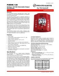
<strong>BG</strong>-<strong>12</strong>S de Acción Singular<br />
<strong>BG</strong>-<strong>12</strong>L de Acción Doble<br />
(Mostrada Activada)<br />
Instrucciones de Alambrado para la <strong>BG</strong>-<strong>12</strong>, <strong>BG</strong>-<strong>12</strong>L y la <strong>BG</strong>-<strong>12</strong>LSP<br />
1) Si está semi-empotrando, proceda al paso 4.<br />
2) Antés de instalar la estación, hale todo el alambrado necesario a través de la caja posterior y el <strong>BG</strong>-TR opcional.<br />
3) Instale la caja posterior o el <strong>BG</strong>-TR antes de alambrar la estación.<br />
4) Remueva la cantidad correcta de aislación del alambre. La placa posterior de la estación está moldeada con un medidor para medir la<br />
cantidad de aislación que necesita ser removida.<br />
5) Conecte el alambrado desde el IDC del panel de control, o cualquier dispositivo previo en el IDC, a los terminales 1 y 2 en el bloque de<br />
conexiones de la estación. Conecte el proximo dispositivo en el IDC o el Resistor de Fin-de-Línea (ELR) a los terminales 1 y 2.<br />
6) Mantenga la polaridad consistente con todas las conexiones a través del IDC.<br />
Instrucciones de Alambrado para la <strong>BG</strong>-<strong>12</strong>S<br />
Siga las instrucciones 1 a la 3 arriba, y luego proceda con los pasos 4 y 5:<br />
4) Conecte el alambrado de campo desde el IDC del FACP o desde el dispositivo previo en el IDC, a los cables flexibles de la estación.<br />
Conecte el alambre del IDC positivo (+) al cable flexible rojo, y el alambre del IDC (-) al cable flexible negro. Luego, conecte el alambre<br />
positivo (+) que está yendo al próximo dispositivo o a un ELR al cable flexible positivo(+) rojo restante. Conecte el alambre negativo<br />
(-) que está yendo al proximo dispositivo o a un ELR al cable flexible negativo (-) negro restante.<br />
5) Mantenga la polaridad consistente con todas las conexiones a través del IDC.<br />
STRIP GAUGE<br />
Funcionamiento<br />
Para activar una estación de acción singular, simplemente hale hacia abajo el manubrio. Para activar las estaciones de acción<br />
doble, empuje y luego hale el manubrio hacia abajo. La palabra ‘ACTIVATED’ aparecerá después de que el manubrio haya<br />
sido halado. La estación queda en la posición de activado hasta el rearme.<br />
1) Para rearmar las estaciones de cerradura hexagonal <strong>BG</strong>-<strong>12</strong>S y <strong>BG</strong>-<strong>12</strong>, entre la llave hexagonal de 9/64 pulgadas dentro de<br />
la cerradura hasta que está sentada firmemente y girela hacia la izquierda.<br />
Para rearmar las estaciones de cerradura de llave <strong>BG</strong>-<strong>12</strong>L y <strong>BG</strong>-<strong>12</strong>LSP, entre la llave y girela hacia la izquierda.<br />
NEGRO<br />
2) Habra la puerta hasta que el manubrio regrese a la posición ‘NORMAL’.<br />
3) Cierre la puerta. Al cerrar la puerta el interruptor es rearmado a la posición de ‘NORMAL’.<br />
Nota – Abriendo la puerta de la estación no activara o desactivara el interruptor de alarma.<br />
ROJO<br />
Cables flexibles Negro<br />
Entrada/salida(-)<br />
Rojo entrada/salida (+)<br />
AVISO<br />
Instale la estación de acuerdo a las instrucciones proporcionadas, normas de NFPA aplicables, códigos Eléctricos y de Fuego locales y nacionales y los<br />
requisitos de la Autoridad Teniendo la Jurisdicción (AHJ). Conduzca pruebas regulares de los dispositivos utilizando las normas apropiadas de NFPA.<br />
Falla de seguir estas instrucciones puede resultar en falla del dispositivo de reportar una condición de alarma. <strong>Fire</strong> <strong>Lite</strong> no es responsable por<br />
dispositivos que hayan sido instalados, probados o mantenidos inapropiadamente.<br />
Para el cumplimiento con ADA, si el piso claro solamente permite el alcance frontal a un objeto, la altura de alcance delantera permitida es 48 pulgadas<br />
(<strong>12</strong>1.92cm). Si el piso claro permite el alcanze paralelo por una persona en una silla de ruedas, la altura máxima de lado permitida es 54 pulgadas<br />
(137.16cm).<br />
Documento 50964 Revisión B ECN 98-461 08/04/99<br />
✵ ✳ ✰✡ ✴ ✔✔✔✐✙✙ ✑<br />
Cables Flexibles de la <strong>BG</strong>-<strong>12</strong><br />
de Acción Singular<br />
<strong>12</strong>34567890<strong>12</strong>34567890<br />
<strong>12</strong>34567890<strong>12</strong>34567890<br />
<strong>12</strong>34567890<strong>12</strong>3<br />
<strong>12</strong>34567890<strong>12</strong>3<br />
<strong>12</strong>34567890<strong>12</strong>345678901<br />
<strong>12</strong>34567890<br />
<strong>12</strong>34567890<br />
<strong>12</strong>34567890<br />
<strong>12</strong>34567890<strong>12</strong>3<br />
<strong>12</strong>34567890<strong>12</strong>3<br />
<strong>12</strong>34567890<br />
Hacia el proximo<br />
Desade el FACP<br />
dispositivo<br />
IDC IDC<br />
<strong>12</strong>34567890<strong>12</strong>345678901<br />
<strong>12</strong>34567890<strong>12</strong>3<br />
<strong>12</strong>34567890<strong>12</strong>3<br />
<strong>12</strong>34567890<strong>12</strong>34567890<strong>12</strong><br />
<strong>12</strong>34567890<strong>12</strong>345678901<br />
<strong>12</strong>34567890<strong>12</strong>3<br />
<strong>12</strong>34567890<strong>12</strong>34567890<strong>12</strong><br />
<strong>12</strong>345678<br />
<strong>12</strong>34567890<strong>12</strong>34567890<strong>12</strong><br />
<strong>12</strong>34567890<strong>12</strong>3<br />
<strong>12</strong>345678<br />
<strong>12</strong>34567890<strong>12</strong>345678901<br />
From <strong>12</strong>34567890<strong>12</strong>3 FACP To <strong>12</strong>34567890<strong>12</strong>34567890<strong>12</strong><br />
<strong>12</strong>345678<br />
Next Addresable <strong>12</strong>345<br />
Device<br />
<strong>12</strong>34567890<strong>12</strong>3<br />
<strong>12</strong>345678<br />
<strong>12</strong>345<br />
IDC<br />
IDC<br />
<strong>12</strong>345678<br />
<strong>12</strong>34567890<strong>12</strong>3<br />
STRIP GAUGE<br />
Alambrado de la <strong>BG</strong>-<strong>12</strong>, <strong>12</strong>L,<br />
<strong>12</strong>LSP de Acción Doble<br />
¡Advertencia! No enlace el alambrado debajo de los terminales. Rompa la corrida de alambre para mantener la supervisión.<br />
✵ ✳ ✰✡ ✴ ✔✔✔✐✙✙✑<br />
<strong>BG</strong>-<strong>12</strong>S / <strong>BG</strong>-<strong>12</strong><br />
Herramienta hexagonal de 9-64pulgadas<br />
tiene que estar sentada<br />
apropiadamente para funcionar<br />
<strong>12</strong>34567890<strong>12</strong>34567890<strong>12</strong><br />
<strong>12</strong>34567890<strong>12</strong>3