AKO-14012 AKO-14023, AKO-140XX, AKO-141XX. AKO-14123
AKO-14012 AKO-14023, AKO-140XX, AKO-141XX. AKO-14123
AKO-14012 AKO-14023, AKO-140XX, AKO-141XX. AKO-14123

You also want an ePaper? Increase the reach of your titles
YUMPU automatically turns print PDFs into web optimized ePapers that Google loves.
GB<br />
CONTROLLER INSTRUCTIONS AND PROGRAMMING:<br />
Thermometers and thermostats<br />
with 1 probe and 1 relay: <strong>AKO</strong>-<strong>14012</strong><br />
<strong>AKO</strong>-<strong>14023</strong>, <strong>AKO</strong>-<strong>140XX</strong>, <strong>AKO</strong>-<strong>141XX</strong>.<br />
<strong>AKO</strong>-<strong>14123</strong>,<br />
®<br />
PUBLICACIÓN<br />
1411H210<br />
Edición 07<br />
GENERAL DESCRIPTION:<br />
Electronic thermometers and thermostats for panel, suitable for displaying, controlling<br />
and adjusting cold (with manual and automatic programmable defrosting) or<br />
heat generators.<br />
VERSIONS:<br />
MODEL FUNCTION FASTENING RELAY<br />
TECHNICAL DATA:<br />
Temperature range: . . . . . . . . . . . . . . . . . . . . . . . . . . . . . . . . . . . -50ºC to 99ºC<br />
NTC probe input: . . . . . . . . . . . . . . . . . . . . . . . . . . . . . . . . . . . Ref. <strong>AKO</strong>-149XX<br />
Controller accuracy: . . . . . . . . . . . . . . . . . . . . . . . . . . . . . . . . . . . . . . . . . . . ±1ºC<br />
Probe tolerance at 25ºC: . . . . . . . . . . . . . . . . . . . . . . . . . . . . . . . . . . . . . . ±0,4ºC<br />
Working ambient temperature: . . . . . . . . . . . . . . . . . . . . . . . . . . . . . 5ºC to 50ºC<br />
Storage ambient temperature: . . . . . . . . . . . . . . . . . . . . . . . . . . . . -30ºC to 70ºC<br />
-with independent mounting<br />
-with characteristic of automatic operation action,<br />
Control device classification:<br />
Type 1.B<br />
-to be used in clean situation<br />
-logical medium (software) class A<br />
INSTALLATION:<br />
Controller:<br />
The thermometer or thermostat must be installed in a place protected from vibrations,<br />
water and corrosive gases, and where the ambient temperature does not surpass<br />
the values specified in the technical data.<br />
For the equipment for panel to be suitable having IP65 protection the gasket should<br />
be installed properly between the apparatus and the perimeter of the panel cut-out<br />
where it is to be fitted.<br />
Probe:<br />
To give a correct reading, the probe has to be installed in a place without heat<br />
influences other than the temperature that is to be measured or controlled.<br />
Connection:<br />
See diagram in the unit rating plate.<br />
The probe and its lead should NEVER be installed in a conduct next to power,<br />
control or power supply wiring systems.<br />
The power supply circuit should be connected with a switch for disconnection of<br />
minimum 2A, 230V, located near the unit. The connection cables should be H05VV-<br />
F 2x0,5mm 2 or H05V-K 1x0,5mm 2 type, to posterior part of the unit.<br />
Section of connecting wires for relays contacts must be between 1mm 2 and 2,5 mm 2 .<br />
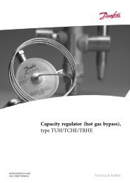
Fastening:<br />
POWER SUPPLY 50/60Hz<br />
<strong>AKO</strong>-<strong>14012</strong> Thermometer For panel - 12/24 V ±10% 76/55 mA,<br />
<strong>AKO</strong>-<strong>14023</strong> Thermometer For panel - 230 V ±10% 6,7 mA,<br />
<strong>AKO</strong>-14031 Cal. thermometer For panel - 230 V ±10% 6,7 mA,<br />
<strong>AKO</strong>-14112 Thermostat For panel 8A, cos =1 12/24 V ±10% 110/71 mA,<br />
<strong>AKO</strong>-<strong>14123</strong> Thermostat For panel 8A, cos =1 230 V ±10% 8,2 mA,<br />
The <strong>AKO</strong>-14031 model has a probe calibration feature.<br />
44<br />
máx.<br />
18 mm<br />
3<br />
1<br />
2<br />
28,5<br />
PANEL CUT-OUT<br />
61,5 70,5<br />
To fix the unit, place the fasteners 1 via the sliders 2 as shown in the figure. Move<br />
the fasteners in the direction of the arrow. Press tab 3 to move the fasteners in the<br />
opposite direction of the arrow.<br />
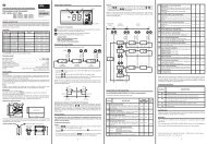
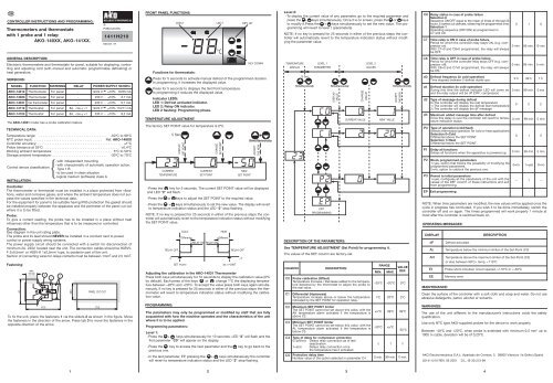
FRONT PANEL FUNCTIONS:<br />
Functions for thermostats:<br />
Press for 5 seconds to activate manual defrost of the programmed duration.<br />
In programming, it increases the displayed value.<br />
Press for 5 seconds to displays the Set Point temperature.<br />
In programming it reduces the displayed value.<br />
Indicator LEDS:<br />
LED 1: Defrost activated indicator.<br />
LED 2: Relay ON indicator.<br />
LED 2 flashing: Programming phase.<br />
TEMPERATURE ADJUSTMENT:<br />
The factory SET POINT value for temperature is 0ºC.<br />
-Press the key for 5 seconds. The current SET POINT value will be displayed<br />
and LED “2” will flash.<br />
-Press the or keys to adjust the SET POINT to the required value.<br />
-Press the + keys simultaneously to set the new value. The display will revert<br />
to temperature indication status and the LED “2” stop flashing.<br />
NOTE: If no key is pressed for 25 seconds in either of the previous steps the controller<br />
will automatically revert to the temperature indication status without modifying<br />
the SET POINT value.<br />
Adjusting the calibration in the <strong>AKO</strong>-14031 Thermometer<br />
Press both keys simultaneously for 10 seconds to display the calibration value (0ºC<br />
by default). Each press of the keys or change 1ºC the displaying temperature<br />
between –20ºC and +20ºC. To accept the value press both keys again simultaneously.<br />
If no key is pressed for 25 seconds in either of the previous steps the thermometer<br />
will revert to temperature indication status without modifying the calibration<br />
value.<br />
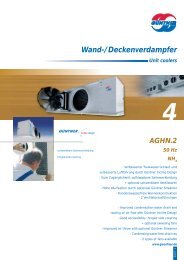
PROGRAMMING:<br />
LED 2 LED 1 KEY UP<br />
5 Sec.<br />
CURRENT<br />
TEMPERATURE<br />
RELAY OFF<br />
DISPLAY<br />
SET POINT<br />
COLD<br />
Different.<br />
CURRENT<br />
SET POINT<br />
RELAY ON RELAY ON<br />
CHANGE<br />
SET POINT<br />
The parameters may only be programmed or modified by staff that are fully<br />
acquainted with how the machine operates and the characteristics of the unit<br />
where it is to be applied.<br />
Programming parameters:<br />
Level 1:<br />
-Press the + keys simultaneously for 10 seconds. LED “2” will flash and the<br />
first parameter “C0” will appear on the display.<br />
-Press the key to access the next parameter and the key to go back to the<br />
previous one.<br />
-In the last parameter, EP, pressing the + keys simultaneously the controller<br />
will revert to temperature indication status and the LED “2” stop flashing.<br />
HEAT<br />
Different.<br />
NEW<br />
SET POINT<br />
RELAY OFF<br />
-T +T<br />
SET POINT<br />
SET POINT<br />
Level 2:<br />
-To display the current value of any parameter, go to the required parameter and<br />
press the + keys simultaneously. Once it is on screen, press the or keys<br />
to modify it.Press the + keys simultaneously to set the new value. The programming<br />
will revert to level 1 (parameters).<br />
NOTE: If no key is pressed for 25 seconds in either of the previous steps the controller<br />
will automatically revert to the temperature indication status without modifying<br />
the parameter value.<br />
KEY DOWN TEMPERATURE<br />
LEVEL 1<br />
LEVEL 2<br />
DISPLAY<br />
PARAMETERS<br />
VALUES<br />
ACCEPT<br />
THE NEW<br />
DESCRIPTION OF THE PARAMETERS:<br />
See TEMPERATURE ADJUSTMENT (Set Point) for programming it.<br />
The values of the DEF column are factory-set.<br />
PARAMETER<br />
C0<br />
C1<br />
C2<br />
C3<br />
10 Sec.<br />
EXIT<br />
PROGRAMMING<br />
DISPLAY<br />
VALUE<br />
DESCRIPTION<br />
CHANGE<br />
VALUE<br />
CURRENT VALUE<br />
Probe calibration (Offset)<br />
Temperature Increase / Decrease added to the temperature<br />
detected by the thermostat to adjust the probe to<br />
the real value.<br />
Differential (Hysteresis)<br />
Temperature increase above or below the temperature<br />
indicated by the SET POINT for operation relay.<br />
Maximum SET POINT limiter<br />
The SET POINT cannot be set above this value, with the<br />
AH temperature alarm activated if the temperature is<br />
above C2.<br />
Minimum SET POINT limiter<br />
The SET POINT cannot be set below this value, with the<br />
AL temperature alarm activated if the temperature is<br />
below C3.<br />
RANGE<br />
MIN. MAX.<br />
–20ºC<br />
VALUE<br />
DEF.<br />
+20ºC 0ºC<br />
1ºC 20ºC 2ºC<br />
xxºC 99ºC 99ºC<br />
-50ºC<br />
NEW VALUE<br />
xxºC<br />
ACCEPT<br />
THE NEW<br />
-50ºC<br />
C4 Type of delay for compressor protection<br />
0=(off/on): Delays relay connection as of last<br />
deactivation.<br />
0 1 0<br />
1=(on): Delays relay connection once<br />
the temperature has it activated.<br />
C5 Protection delay time<br />
Number value of the option selected in parameter C4 0 min. 99 min. 0 min.<br />
C6 Relay status in case of probe failure<br />
Selection 0<br />
Sequence ON/OFF equal to the mean of times of the last 24<br />
hours. It carries out defrosts, observing the programmed time.<br />
Selection 1<br />
Operating sequence (OFF/ON) as programmed in<br />
C7 and C8.<br />
C7<br />
C8<br />
d0<br />
d1<br />
d2<br />
d3<br />
P0<br />
P1<br />
P2<br />
P3<br />
Time relay is ON in case of probe failure<br />
Period for which the controller relay stays ON, (e.g. compressor<br />
on).<br />
With C7=0 and C8≠0 programmed, the relay will always<br />
be OFF.<br />
Time relay is OFF in case of probe failure<br />
Period for which the controller relay stays OFF (e.g. compressor<br />
off).<br />
With C8=0 and C7≠0 programmed, the relay will always<br />
be ON.<br />
Defrost frequency (in cold operation)<br />
Time elapsed between 2 defrost starts-ups.<br />
Defrost duration (in cold operation)<br />
During this time the defrost indicator LED will come on<br />
and the relay output will be off (OFF: compressor)<br />
Type of message during defrost<br />
0=The controller will display the real temperature<br />
1=The controller will display the defrost start temperature<br />
2=The controller will display the dF message<br />
Maximum added message time after defrost<br />
Once this delay is over the controller will revert to temperature<br />
indication status.<br />
Type of operation (cold/heat)<br />
Selects thermostat operation for cold or heat applications<br />
Selection 0=Cold<br />
Differential above the SET POINT<br />
Selection 1=Heat<br />
Differential below the SET POINT<br />
Delay all functions<br />
Delays all functions when the apparatus is powered up.<br />
Block programmed parameters<br />
1=yes, option that blocks the possibility of modifying the<br />
programmed parameters.<br />
0=no, option to unblock the previous one.<br />
Revert to initial parameters<br />
1=yes, configures all the parameters of the unit with the<br />
values of the DEF column of these instructions and exit<br />
from programming.<br />
EP Exit programming<br />
0 min. 99 min. 10 min.<br />
0 min. 99 min. 5 min.<br />
0 h 99 h 1 h<br />
0 min. 99 min. 0 min<br />
0 2 2<br />
0 min 99 min 5 min<br />
0 1 0<br />
0 min. 99 min 0 min<br />
0=no. 1=yes 0=no<br />
– 1 –<br />
NOTE: When time parameters are modified, the new values will be applied once the<br />
cycle in progress has concluded. If you wish it to be done immediately, switch the<br />
controller off and on again. The times programmed will work properly 1 minute at<br />
most after the controller is switched back on.<br />
OPERATING MESSAGES:<br />
DISPLAY<br />
dF<br />
AL<br />
AH<br />
E1<br />
EE<br />
MAINTENANCE:<br />
Defrost activated.<br />
DESCRIPTION<br />
Temperature below the minimum limiter of the Set-Point (C3)<br />
Temperature above the maximum limiter of the Set-Point (C2)<br />
or else between 99ºC< temp. 110ºC or
E<br />
INSTRUCCIONES Y PROGRAMACIÓN DE CONTROLADORES:<br />
Termómetros y termostatos<br />
con 1 sonda y 1 relé:<br />
<strong>AKO</strong>-<strong>14023</strong>, <strong>AKO</strong>-<strong>140XX</strong>, <strong>AKO</strong>-<strong>141XX</strong>.<br />
<strong>AKO</strong>-<strong>14123</strong>,<br />
®<br />
PUBLICACIÓN<br />
1411H210<br />
Edición 07<br />
DESCRIPCIÓN GENERAL:<br />
Termómetros y termostatos electrónicos panelables, adecuados para visualizar,<br />
controlar y regular generadores de frio (con desescarche automático programable y<br />
manual) o de calor.<br />
VERSIONES:<br />
MODELO FUNCIÓN ANCLAJE RELÉ ALIMENTACIÓN, 50/60 Hz<br />
<strong>AKO</strong>-<strong>14012</strong> Termómetro Panelable - 12/24 V ±10% 76/55mA,<br />
<strong>AKO</strong>-<strong>14023</strong> Termómetro Panelable - 230 V ±10% 6,7 mA,<br />
<strong>AKO</strong>-14031 Termómetro cal. Panelable - 230 V ±10% 6,7 mA,<br />
<strong>AKO</strong>-14112 Termostato Panelable 8A, cos =1 12/24 V ±10% 110/71mA,<br />
<strong>AKO</strong>-<strong>14123</strong> Termostato Panelable 8A, cos =1 230 V ±10% 8,2 mA,<br />
El modelo <strong>AKO</strong>-14031 permite ajustar la calibración de la sonda<br />
DATOS TÉCNICOS:<br />
Rango de temperatura: . . . . . . . . . . . . . . . . . . . . . . . . . . . . . . . . . . -50ºC a 99ºC<br />
Entrada sonda NTC: . . . . . . . . . . . . . . . . . . . . . . . . . . . . . . . . . Ref. <strong>AKO</strong>-149XX<br />
Precisión del controlador: . . . . . . . . . . . . . . . . . . . . . . . . . . . . . . . . . . . . . . ±1ºC<br />
Tolerancia de la sonda a 25ºC: . . . . . . . . . . . . . . . . . . . . . . . . . . . . . . . . . ±0,4ºC<br />
Temp. ambiente de trabajo: . . . . . . . . . . . . . . . . . . . . . . . . . . . . . . . . 5ºC a 50ºC<br />
Temp. ambiente de almacenaje: . . . . . . . . . . . . . . . . . . . . . . . . . . . -30ºC a 70ºC<br />
Clasificación dispositivo de control:<br />
INSTALACIÓN:<br />
Controlador:<br />
El termómetro o termostato debe ser instalado en un sitio protegido de las vibraciones,<br />
del agua y de los gases corrosivos, y donde la temperatura ambiente no<br />
supere los valores reflejados en los datos técnicos.<br />
Para que los equipos panelables tengan un grado de protección IP65 deberá instalarse<br />
correctamente la junta entre el aparato y el perímetro del hueco del panel<br />
donde deba montarse.<br />
Sonda:<br />
Para que la lectura sea correcta, la sonda se ha de instalar en un sitio sin influencias<br />
térmicas ajenas a la temperatura que se desea medir o controlar.<br />
Conexionado:<br />
Ver esquema en la etiqueta de características de los aparatos.<br />
La sonda y su cable correspondiente NUNCA deben instalarse en una conducción<br />
junto con cables de potencia, control o alimentación.<br />
El circuito de alimentación debe estar provisto de un interruptor para su desconexión<br />
de mínimo 2A, 230V, situado cerca del aparato. Los cables entrarán por la parte<br />
posterior y serán del tipo H05VV-F 2x05 mm 2 o H05V-K 1x05mm 2 .<br />
Los cables para el conexionado de los contactos de los relés, deberán tener una<br />
sección de entre 1mm 2 y 2,5 mm 2 .<br />
Anclaje:<br />
44<br />
máx.<br />
18 mm<br />
3<br />
1<br />
2<br />
-de montaje independiente<br />
-de característica de funcionamiento<br />
automático acción Tipo 1.B<br />
-para utilización en situación limpia<br />
-soporte lógico (software) clase A<br />
Para la fijación del aparato situar los anclajes 1 sobre las guias 2 en la posición de<br />
la figura. Desplazar el anclaje en el sentido de la flecha. Presionando la pestaña 3<br />
puede desplazarse el anclaje en sentido contrario a la flecha.<br />
28,5<br />
HUECO PANEL<br />
61,5 70,5<br />
FUNCIONES DEL FRONTAL<br />
Funciones para termostatos:<br />
Pulsando durante 5 segundos se activa un desescarche manual de la duración<br />
que se haya programado.<br />
En programación, sube el valor que se está visualizando.<br />
Pulsando durante 5 segundos se visualiza la temperatura del PUNTO DE<br />
AJUSTE (Set Point).<br />
En programación, baja el valor que se está visualizando.<br />
LEDS indicadores:<br />
LED 1: Indicador de desescarche activado.<br />
LED 2: Indicador de relé activado (ON).<br />
LED 2 intermitente: Fase de programación.<br />
AJUSTE DE LA TEMPERATURA:<br />
El valor de fábrica, de AJUSTE DE TEMPERATURA (Set Point) por defecto es de 0°C.<br />
-Pulse la tecla durante 5 segundos. Se visualizará el valor del AJUSTE (Set Point)<br />
actual y se iluminará el LED “2” de forma intermitente.<br />
-Pulse las teclas ó para seleccionar el AJUSTE (Set Point) al valor deseado.<br />
-Pulse las teclas + simultáneamente para fijar el nuevo valor. Al realizar esta<br />
operación, el display volverá a la situación de indicación de temperatura y el LED<br />
“2” dejará de iluminarse de forma intermitente.<br />
NOTA: Si no se pulsa tecla alguna durante 25 segundos en cualquiera de los pasos<br />
anteriores, el controlador volverá automáticamente a la situación de indicación de<br />
temperatura, sin modificar el valor del AJUSTE (Set Point).<br />
Ajuste de la calibración en el termómetro ref. <strong>AKO</strong>-14031<br />
Pulsar las dos teclas simultáneamente durante 10 segundos y se visualiza el valor<br />
de la calibración (por defecto 0ºC). Cada pulsación de las teclas ó varia 1ºC<br />
la visualización de temperatura entre –20ºC y +20ºC. Para aceptar el valor volver a<br />
pulsar simultáneamente las dos teclas. Si no se pulsa tecla alguna durante 25<br />
segundos en cualquiera de los pasos anteriores, el termómetro volverá a la situación<br />
de indicación de temperatura sin modificar el valor de la calibración.<br />
PROGRAMACIÓN:<br />
LED 2 LED 1 TECLA SUBIR<br />
5 Seg.<br />
INDICACION<br />
TEMPERATURA<br />
RELÉ OFF<br />
VISUALIZAR<br />
AJUSTE<br />
FRIO<br />
AJUSTE<br />
ACTUAL<br />
VARIAR<br />
AJUSTE<br />
CALOR<br />
Diferenc.<br />
Diferenc.<br />
RELÉ ON RELÉ ON<br />
NUEVO<br />
AJUSTE<br />
RELÉ OFF<br />
-T +T<br />
PUNTO DE AJUSTE (SET POINT) PUNTO DE AJUSTE (SET POINT)<br />
TECLA BAJAR<br />
ACEPTAR<br />
EL NUEVO<br />
Los parámetros sólo deben ser programados o modificados por personal que<br />
conozca el funcionamiento y las posibilidades del equipo donde se aplica.<br />
Programación de parámetros:<br />
Nivel 1:<br />
-Pulse simultáneamente las teclas + durante 10 segundos. El LED “2” se iluminará<br />
de forma intermitente y en el display aparecerá el primer parámetro “C0”.<br />
-Pulse la tecla para acceder al parámetro siguiente y la tecla para retroceder<br />
al parámetro anterior.<br />
-Situándonos en el último parámetro EP, pulsando las teclas + simultánemente,<br />
el controlador volverá a la situación de indicación de temperatura y el LED<br />
“2” dejará de iluminarse de forma intermitente.<br />
Nivel 2:<br />
-Para ver el valor actual de cualquier parámetro, sitúese en el que se desea y pulse<br />
las teclas + simultáneamente. Una vez visualizado, si quiere modificarlo pulse<br />
las teclas ó .<br />
-Pulse las teclas + simultáneamente para fijar el nuevo valor. Al realizar esta<br />
operación la programación volverà al nivel 1 (parámetros).<br />
NOTA: Si no se pulsa tecla alguna durante 25 segundos en cualquiera de los pasos<br />
anteriores, el controlador volverá automáticamente a la situación de indicación de<br />
temperatura, sin modificar el valor de los parámetros.<br />
INDICACIÓN<br />
TEMPERATURA<br />
DESCRIPCIÓN DE LOS PARÁMETROS:<br />
Para programar el PUNTO DE AJUSTE (Set Point) ver<br />
AJUSTE DE LA TEMPERATURA<br />
Los valores de la columna DEF. vienen programados de fábrica.<br />
PARÁMETRO<br />
C0<br />
C1<br />
C2<br />
C3<br />
10 Seg.<br />
NIVEL 1<br />
PARAMETROS<br />
SALIDA<br />
PROGRAMACIÓN<br />
VISUALIZAR<br />
VALOR<br />
DESCRIPCIÓN<br />
NIVEL 2<br />
VALORES<br />
VARIAR<br />
VALOR<br />
VALOR ACTUAL<br />
Calibración de la sonda (Offset)<br />
Incremento / Decremento de temperatura que se añade<br />
a la temperatura detectada por el termostato para ajustar<br />
la sonda al valor real.<br />
Diferencial (Hystéresis)<br />
Incremento de temperatura por encima o por debajo de<br />
la temperatura indicada por el PUNTO DE AJUSTE (Set<br />
Point) para que actue el relé<br />
Limitador máximo del PUNTO DE AJUSTE (Set point)<br />
No se podrá fijar un SET POINT por encima de este valor,<br />
apareciendo la indicación de alarma AH si la temperatura<br />
es superior a C2.<br />
Limitador mínimo del PUNTO DE AJUSTE (Set point)<br />
No se podrá fijar un SET POINT por debajo de este valor,<br />
apareciendo la indicación de alarma AL si la temperatura<br />
es inferior a C3.<br />
C4 Tipo de retardo para protección del compresor<br />
0=(off/on): Retardo a la conexión del relé desde su<br />
última desactivación.<br />
1=(on): Retardo a la conexión del relé desde que<br />
la temperatura manda activarlo.<br />
C5 Tiempo de retardo de la protección<br />
Valor numérico de la opción elegida en el parámetro C4<br />
RANGO<br />
MIN. MAX.<br />
–20ºC<br />
NUEVO VALOR<br />
ACEPTAR<br />
EL NUEVO<br />
VALOR<br />
DEF.<br />
+20ºC 0ºC<br />
1ºC 20ºC 2ºC<br />
xxºC 99ºC 99ºC<br />
-50ºC xxºC -50ºC<br />
0 1 0<br />
0 min. 99 min. 0 min.<br />
C6<br />
C7<br />
C8<br />
d0<br />
d1<br />
d2<br />
d3<br />
P0<br />
P1<br />
P2<br />
P3<br />
EP<br />
Estado del relé con sonda averiada<br />
Selección 0<br />
Secuencia ON/OFF promedio de las últimas 24 horas.<br />
Realiza los desescarches respetando su tiempo programado.<br />
Selección 1<br />
Secuencia de funcionamiento (OFF/ON) según lo programado<br />
en C7 y C8.<br />
Tiempo relé conectado (ON) en caso de fallo de sonda<br />
Periodo en que el controlador permanece con el relé<br />
conectado, (Ej. marcha compresor).<br />
Programando C7=0 y C8≠0, el relé estará siempre desconectado<br />
(OFF).<br />
Tiempo relé desconectado (OFF) en fallo de sonda<br />
Periodo en que el controlador permanece con el relé desconectado,<br />
(Ej. paro compresor).<br />
Programando C8=0 y C7≠0 , el relé estará siempre<br />
conectado (ON).<br />
Frecuencia de desescarches (funcionamiento frÌo)<br />
Tiempo entre 2 inicios de desescarche<br />
Duración de los desescarches (funcionamiento frÌo)<br />
Durante este tiempo se activará el LED indicador de<br />
desescarche y se desactivará la salida (OFF:compresor)<br />
Tipo de mensaje durante el desescarche<br />
0=El controlador mostrará la temperatura real<br />
1=El controlador mostrará la temperatura inicio desescarche<br />
2=El controlador mostrará el mensaje dF<br />
Tiempo máx. añadido de mensaje después del desescarche<br />
Al finalizar este retardo el controlador volverá a la situación<br />
de indicación de temperatura.<br />
Tipo de funcionamiento (frio/calor)<br />
Selección del funcionamiento del termostato para aplicaciones<br />
del frio o del calor<br />
Selección 0=Frio<br />
Diferencial por encima del PUNTO DE AJUSTE (Set point)<br />
Selección 1=Calor<br />
Diferencial por debajo del PUNTO DE AJUSTE (Set point)<br />
Retardo de todas las funciones<br />
Retardo de todas las funciones cuando el aparato recibe<br />
alimentación eléctrica.<br />
Bloqueo de parámetros programados<br />
1=sÌ, opción que bloquea la posibilidad de modificación<br />
de los parámetros que se hayan programado.<br />
0=no, opción que desbloquea la anterior.<br />
Volver a los parámetros iniciales<br />
1=sÌ, configura todos los parámetros del equipo con los<br />
valores de la columna DEF de estas instrucciones y sale<br />
inmediatamente de programación.<br />
Salida de programación<br />
0<br />
0 min. 99 min. 10 min.<br />
0 min. 99 min. 5 min.<br />
0 h 99 h 1 h<br />
0 min. 99 min. 0 min.<br />
0 2 2<br />
0 min 99 min 5 min<br />
0 1 0<br />
0 min. 99 min 0 min<br />
0=no. 1=si 0=no<br />
NOTA: Cuando se modifican los parámetros de tiempo, los nuevos valores, los aplicará<br />
una vez finalizado el ciclo que estaba realizando. Para que lo haga inmediatamente,<br />
desconectar y volver a conectar el controlador. Los tiempos programados<br />
funcionarán correctamente al cabo de 1 minuto como máximo de haber conectado<br />
el controlador.<br />
MENSAJES DE FUNCIONAMIENTO:<br />
VISUALIZACIÓN<br />
dF<br />
AL<br />
AH<br />
E1<br />
EE<br />
MANTENIMIENTO:<br />
Desescarche activado.<br />
Temperatura por debajo del limitador mínimo del Punto de Ajuste (C3)<br />
Temperatura por encima del limitador máximo del Punto de Ajuste (C2)<br />
o bien entre 99ºC< temp. 110ºC ó