ECO-CCE - AstralPool
ECO-CCE - AstralPool
ECO-CCE - AstralPool

You also want an ePaper? Increase the reach of your titles
YUMPU automatically turns print PDFs into web optimized ePapers that Google loves.
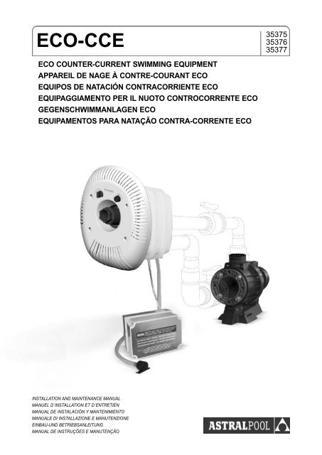
<strong>ECO</strong>-<strong>CCE</strong><br />
35375<br />
35376<br />
35377<br />
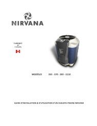
<strong>ECO</strong> COUNTER-CURRENT SWIMMING EQUIPMENT<br />
APPAREIL DE NAGE À CONTRE-COURANT <strong>ECO</strong><br />
EQUIPOS DE NATACIÓN CONTRACORRIENTE <strong>ECO</strong><br />
EQUIPAGGIAMENTO PER IL NUOTO CONTROCORRENTE <strong>ECO</strong><br />
GEGENSCHWIMMANLAGEN <strong>ECO</strong><br />
EQUIPAMENTOS PARA NATAÇÃO CONTRA-CORRENTE <strong>ECO</strong><br />
INSTALLATION AND MAINTENANCE MANUAL<br />
MANUEL D´INSTALLATION ET D´ENTRETIEN<br />
MANUAL DE INSTALACIÓN Y MANTENIMIENTO<br />
MANUALE DI INSTALLAZIONE E MANUTENZIONE<br />
EINBAU-UND BETRIEBSANLEITUNG<br />
MANUAL DE INSTRUÇÕES E MANUTENÇÃO
ENGLISH<br />
Contents<br />
Installation and maintenance manual<br />
1 Installation . . . . . . . . . . . . . . . . . . . . . . . . . . . . . . . . . . . . . . . . . . . . . . . . .4<br />
2 Assembly of the unit . . . . . . . . . . . . . . . . . . . . . . . . . . . . . . . . . . . . . . . .4<br />
2a Installation of the housing case (Fig. 1, 2)<br />
2b Assembly of the unit with the pump at a distance (Fig. 3)<br />
2c Assembly of the unit in liner pools<br />
2d Installation of the unit in pre-fabricated pools<br />
3 Electrical installation . . . . . . . . . . . . . . . . . . . . . . . . . . . . . . . . . . . . . . . .5<br />
4 How it works . . . . . . . . . . . . . . . . . . . . . . . . . . . . . . . . . . . . . . . . . . . . . . .6<br />
5 Starting . . . . . . . . . . . . . . . . . . . . . . . . . . . . . . . . . . . . . . . . . . . . . . . . . . .6<br />
6 Winter period . . . . . . . . . . . . . . . . . . . . . . . . . . . . . . . . . . . . . . . . . . . . . . .6<br />
7 Possible causes of breakdown . . . . . . . . . . . . . . . . . . . . . . . . . . . . . . . .7<br />
ANEX Guarantee . . . . . . . . . . . . . . . . . . . . . . . . . . . . . . . . . . . . . . . . . . . . . . . .41<br />
Photos / Technical drawings<br />
Photos / Technical drawings . . . . . . . . . . . . . . . . . . . . . . . . . . . . . . . 38<br />
IMPORTANT<br />
The instructions manual contains essential information on the safety measures to be taken when installing and<br />
using the fence. Therefore, both the installer and the user must read the instructions before assembling and<br />
using the fence.<br />
For optimum performance of the <strong>ECO</strong> counter-current swimming equipment, it is recommended to follow the<br />
instructions given below.<br />
Carefully read and keep these instructions
<strong>ECO</strong> COUNTER-CURRENT EQUIPMENT<br />
1. INSTALLATION<br />
The counter current swimming unit can be installed<br />
in any type or size of pool.<br />
In order to avoid high head losses in the suction<br />
pipework, it is recommended not to exceed<br />
a distance of 20 metres between the housing<br />
case and the pump. Also it must be<br />
remembered to avoid right angle bends in the<br />
tube, trying to ensure that the tubing is installed<br />
as horizontally and as straight as possible.<br />
Since the pump is not self-priming, it is installed<br />
below the water level and in an acessible<br />
place, to allow for its control and maintenance.<br />
The installation must be ventilated to avoid<br />
condensation and to allow for cooling of the<br />
motor. The pump pit must also include a drain<br />
~Ø100 mm., with an anti-return valve to prevent<br />
flooding.<br />
2. ASSEMBLY OF THE UNIT<br />
2a. Installation of the housing case<br />
(Fig. 1 - 2)<br />
The housing case (36) may be adapted to concrete<br />
liner and prefabricated pools. In the case<br />
of liner and prefabricated pools you will need to<br />
add the corresponding accessories for installation<br />
(48).<br />
The housing case should be installed such that<br />
the two gland holes PG16 (37) are situated at<br />
the upper end, whilst the centre of the main<br />
nozzle should be about 30 cms. below the<br />
water level (Fig. 1).<br />
If you do not want to install the unit in the case<br />
immediately, the case can be sealed, using the<br />
fittings provided (Fig. 1), in the following way:<br />
Place the sealing gaskets (38) in the connecting<br />
flange (17) and fix it to the case using six<br />
nuts M8 (32) and the corresponding washers.<br />
Put the blind joints (64) and the packing glands<br />
into the screwholes PG16 (37). Connect the 2<br />
plugs RG2” (63) to the connecting flange,<br />
having previously put "teflon" on the thread of<br />
the plugs. Put on the protection cover (61) with<br />
the screws (62) provided in order to close up<br />
the interior of the housing case.<br />
Where the pools is of a shuttering type construction<br />
with walls of 24 cms. thick, the housing<br />
should be installed as per (Fig. 2).<br />
2b. Assembly of the unit with the pump<br />
at a distance (Fig. 3)<br />
After the pool is built, clean up the housing<br />
case (36). The return inlet unit comes with all<br />
the necessary fittings. Put the sealing gasket<br />
(38) onto the flange connection and screw<br />
them tightly onto the housing case from the<br />
inside using the 6 nuts M8 and washers, as<br />
indicated in (Fig. 3).<br />
Thread the suction tube and return pipe (31)<br />
onto the flange. If there is access to the back<br />
part of the housing case, pass the suction and<br />
control conduits (14) and (22) from the interior<br />
of the pool, thourgh the packing gland holes<br />
PG16, introducing at the same time the return<br />
inlet unit into the case, sliding it onto the return<br />
pipe (31) till it reaches the case wall. At the<br />
back end assemble the two packing glands<br />
PG16 (37) and the corresponding seals to the<br />
conduits (14) and (22). Before fixing the pac-<br />
<strong>ECO</strong> <strong>CCE</strong><br />
ENGLISH<br />
4
<strong>ECO</strong> COUNTER-CURRENT EQUIPMENT<br />
king glands (37) in place gently pull the two<br />
conduits so that thay do not remain bent inside<br />
the case. Lead the control conduit (22) to the<br />
control cabinet and set it up inside the wall conduit.<br />
Put the air inlet valve (20) onto the end of<br />
the suction tube (14), its design allowing it to be<br />
fixed onto the wall above the water level.<br />
If you cannot get to the back end of the housing<br />
case then the suction and control conduits (14)<br />
and (22) must be sealed from inside the housing<br />
case. Put the two packing glands PG16<br />
(37) with the seals onto the conduits and pass<br />
them through the packing gland holes and protection<br />
tubes (assembled before-hand in the<br />
housing case. See (Fig. 3). Put the return inlet<br />
unit next to the return pipe (31) and before<br />
fixing the packing glands slide through the conduits,<br />
leaving the least possible length free to<br />
fix the packing glands, so that when you introduce<br />
the return inlet unit fully into the housing<br />
case the conduits (14) and (22) don't bend.<br />
Lead the control conduit (22) to the control<br />
cabinet and assemble it inside the wall conduit.<br />
Put the valve (20) onto the end of the suction<br />
tube (14).<br />
The propulsion outlet unit is situated right<br />
against the pool wall, fix it in place using 4<br />
screws depending on the thickness of the surface<br />
finish.The assembly allows a tolerance of<br />
0-70 mm.<br />
Glue the PVC piping from the flange connection<br />
to the siting of the pump, the installation of<br />
valves is recommended here for future maintainance<br />
operations.<br />
The pump is fixed onto the floor on cushions<br />
and in a horitzontal position. The 2 outlets of<br />
the pump will be connected to the tubes<br />
coming from the housing case.<br />
2c. Assembly of the unit in liner pools<br />
For this installation, a set of fittings composed<br />
(48), of the flange and sealing gaskets is required.<br />
Installation of the unit is the same as described<br />
beforehand.<br />
2d. Installation of the unit in pre-fabricated<br />
pools<br />
For installation of the unit in pre-fab. pools,<br />
a set of fittings (48), composed of a flange<br />
and sealing gaskets is required. For<br />
assembly instructions procede as described<br />
beforehand.<br />
3. ELECTRICAL INSTALLATION<br />
The electrical installation must be made in<br />
accordance with the regulations concerning<br />
electrical protection in force in each country.<br />
The installation should be made by an<br />
authorised installer. Check that the voltage<br />
coincides with the specifications plaque of the<br />
pump. Use a power cable of 5x4 mm². for the<br />
pump 3,3 kW., of 5x2,5 mm². for the pump 2,6<br />
kW. and 3x2,5 mm². for the 1,5 kW. pump. For<br />
protection, install 16 amp. fuses, and without<br />
fail a circuit breaker of 25/0.03 A. (30 mA).<br />
The control cabinet comes with the following<br />
components: A thermal relay to ensure the protection<br />
of the motor, which must be correctly<br />
regulated, according to the current consump-<br />
5<br />
ENGLISH<br />
<strong>ECO</strong> <strong>CCE</strong>
<strong>ECO</strong> COUNTER-CURRENT EQUIPMENT<br />
tion of each pump, a contactor, an automatic<br />
switch, and a pneumatic switch.<br />
The control cabinet must be installed in a dry<br />
place, and the distance to the pneumatic pushbutton,<br />
situated in the return inlet unit, must not<br />
be greater than 20 metres. When installing the<br />
control conduit ensure that there are no bends.<br />
Depending on the distance, the pneumatic<br />
switch should be adjusted accordingly by<br />
means of the regulation screw.<br />
It is also necessary to check which way the<br />
pump motor rotates, which must coincide with<br />
the way indicated on the body of the pump.<br />
4. HOW IT WORKS<br />
The return inlet unit of the counter-current<br />
swimming unit incorporates all the controls<br />
necessary for its working. It is controlled by a<br />
(STOP-START) button. The amount of air in<br />
the water current is given by the Venturi effect,<br />
which is regulated by means of an air valve,<br />
turning it to the left or the right. This valve also<br />
function as an anti-return valve, when the massage<br />
hose is connected. The return inlet is<br />
adjustable in all ways, and allows you to regulate<br />
the water jet stream, by turning the dial.<br />
5. STARTING<br />
Once having completed the aforementioned<br />
operations, and with the water level ~30 cm.<br />
above the centre of the inlet you can start up<br />
the unit. THE PUMP MUST NEVER WORK<br />
WITHOUT WATER. To start it up open the suction<br />
and return valves (if installed).<br />
1- Switch on pressing the start-button.<br />
2- Check the regulation of the air-water<br />
mix.<br />
3- Check the regulation of the water flow.<br />
(Close the inlet and check that the unit<br />
is correctly sealed).<br />
4- Check that the inlet can be correctly<br />
orientated.<br />
6. WINTER PERIOD<br />
With installations where the pump runs the risk<br />
of getting frozen, it is necessary to empty the<br />
pump. To do this the suction and return valves<br />
must be closed and then the draining plug<br />
should be taken off.<br />
The massage hose is connected directly to the<br />
inlet, lining up the slot on the hose to the pivot<br />
on the inside of the inlet and turning it slightly to<br />
the right.<br />
<strong>ECO</strong> <strong>CCE</strong><br />
ENGLISH<br />
6
<strong>ECO</strong> COUNTER-CURRENT EQUIPMENT<br />
7. POSSIBLE CAUSES OF BREAKDOWN<br />
PROBLEM PROBABLE CAUSE SOLUTION<br />
The unit does not give an<br />
adequate flow.<br />
The pump does not start<br />
or it starts but stops<br />
easily.<br />
The motor turns the wrong<br />
way round.<br />
The pump sucks in air.<br />
The pump is obstructed<br />
(leaves, etc.).<br />
If none of these causes<br />
are recognised call the<br />
maintenance service.<br />
The pneumatic switch<br />
is not sensitive enough.<br />
The pneumatic conduit is<br />
bent or blocked.<br />
Check and correct the way<br />
the motor rotates.<br />
The water level is not high<br />
enough.<br />
The suction pipe is not<br />
correctly sealed.<br />
Clean it out.<br />
Adjust the sensitiveness of<br />
the switch to air pressure.<br />
Check and correct.<br />
Pump is turned off by the<br />
thermal relay of the motor<br />
protection.<br />
The circuit breaker trips.<br />
The regulation is not correct.<br />
The motor is overheated.<br />
One of the phases does not<br />
work.<br />
Check the regulation of the<br />
thermal relay.<br />
The nominal intensity of the<br />
motor and the local conditions<br />
must coincide with the<br />
regulation of the thermal relay.<br />
Cool the motor down and<br />
start it up again later.<br />
Check the fuses.<br />
The installation should be<br />
checked by an electrician.<br />
The air-water mix is poor.<br />
The air suction tube is<br />
tangled.<br />
Check and correct.<br />
7<br />
ENGLISH<br />
<strong>ECO</strong> <strong>CCE</strong>
FRANÇAIS<br />
Index<br />
Manuel d’installation et d’entretien<br />
1 Installation . . . . . . . . . . . . . . . . . . . . . . . . . . . . . . . . . . . . . . . . . . . . . . . . 10<br />
2 Montage de l’appareil . . . . . . . . . . . . . . . . . . . . . . . . . . . . . . . . . . . . . . 10<br />
2a Installation de la boite de scellement (Fig. 1, 2)<br />
2b Montage de l’appareil avec la pompe a distance (Fig. 3)<br />
2c Montage de l’appareil pour piscine liner<br />
2d Montage de l’appareil pour piscine prefabriquee<br />
3 Raccordement electrique . . . . . . . . . . . . . . . . . . . . . . . . . . . . . . . . . . . 11<br />
4 Fonctionnement . . . . . . . . . . . . . . . . . . . . . . . . . . . . . . . . . . . . . . . . . . . 12<br />
5 Mise en marche . . . . . . . . . . . . . . . . . . . . . . . . . . . . . . . . . . . . . . . . . . . 12<br />
6 Maintenanc en periode d’hiver . . . . . . . . . . . . . . . . . . . . . . . . . . . . . . 12<br />
7 Pannes les plus frequentes . . . . . . . . . . . . . . . . . . . . . . . . . . . . . . . . . 13<br />
ANEX Garantie . . . . . . . . . . . . . . . . . . . . . . . . . . . . . . . . . . . . . . . . . . . . . . . . . 41<br />
Photographies / Plans techniques<br />
Photographies / Plans techniques . . . . . . . . . . . . . . . . . . . . . . . . . . . . . . 38<br />
Important<br />
Le manuel d'instructions que vous avez entre les mains contient des informations fondamentales<br />
concernant les mesures de sécurité à adopter lors de l'installation et de la mise en service. C'est<br />
pourquoi, il est indispensable que l'installateur ainsi que l'utilisateur en lisent attentivement les<br />
instructions avant de procéder au montage et à la mise en marche.<br />
Pour obtenir un rendement optimal de la Appareil de nage à contre-courant <strong>ECO</strong>, il convient d'observer les instructions<br />
qui sont indiquées ci-après.<br />
Lisez attentivement ce manuel d'instructions et gardez-le à portée de main pour pouvoir le consulter en cas de<br />
besoin.
APPAREIL DE NAGE À CONTRE-COURANT <strong>ECO</strong><br />
1. INSTALLATION<br />
L´appareil de nage à contre-courant peut<br />
s´adapter à tous types de constructions et<br />
dimensions de piscines.<br />
Pour éviter toute perte de charge trop importante<br />
à l´aspiration, nous recommandons de ne pas<br />
dépasser une distance de 20 mètres, étant donné<br />
qu´à cette distance, l´intallation de la tuyauterie<br />
doit être éffectuée le plus directement possible,<br />
horizontalement avec des courbes (sans coudes).<br />
La pompe n´étant pas auto-aspirante, elle<br />
doit être en dessous du niveau de l´eau et<br />
accessible pour le contrôle et entretien. Le<br />
local de l´appareil doit être ventilé pour éliminer<br />
toute condensation et faciliter le refroidissement<br />
du moteur. Il faut prévoir une évacuation<br />
de ~Ø100 mm. avec clapet anti-retour.<br />
2. MONTAGE DE L´APPAREIL<br />
2a. Installation de la boite de scellement<br />
(Fig. 1, 2)<br />
Les boite de scellement (36) sont adaptables<br />
aux piscines en béton, en liner et préfabriquées,<br />
dans ces deux derniers cas il est nécessaire<br />
pour une installation correcte d’utiliser les compléments<br />
pour piscine préfabriquée (48).<br />
La boite de scellement s’installera de manière<br />
à ce que les 2 orifices pour les presses étoupes<br />
PG16 (37) soient en partie supérieure ce<br />
qui situe le centre de la bouche de refoulement<br />
approximativement à 30 cm. au dessous du<br />
niveau d’eau, (Fig. 1).<br />
Pour l´installation provisoire de l´appareil de<br />
nage à contre-courant, on peut obtenir l´étanchéité<br />
de la boite de scellement en montant les<br />
éléments fournis (Fig. 1) de la façon suivante:<br />
Placer le joint d´étanchéité (38) dans la bride de<br />
connexion (17) et fixer les différentes pièces<br />
avec ces 6 écrous M8 (32) et ces rondelles.<br />
Placer dans les trous PG16 correspondants, les<br />
2 joints borgnes (64) avec ces presse etoupes<br />
(37). Monter les 2 bouchons RG2" (63) dans la<br />
bride de connexion, avant tout, nous devrons<br />
mettre du téflon sur le pas de vis. Pour éviter<br />
l´accés à l´íntérieur de la boite de scellement, on<br />
mettra le cache de protection (61), et on la fixera<br />
avec les vis (62).<br />
Dans le système de piscine avec coffrage et des<br />
murs de 24 cm., on placera la boite de scellement<br />
comme indiqué sur la (Fig. 2).<br />
2b. Montage de l´appareil avec la pompe a<br />
distance (Fig. 3)<br />
Après la construction de la piscine, nous procéderons<br />
au nettoyage de la boite de scellement<br />
(36). Le refoulement est fourni avec tous les<br />
accessoires de connexion. Placer le joint<br />
d´etanchéité (38) avec la bride, et monter<br />
directement sur la boite de scellement de l´intérieur,<br />
grâce aux six boulons M8 et rondelles,<br />
suivant les indications (Fig. 3).<br />
Visser le tube d'aspiration et le tube d´impulsion<br />
(31) sur les sorties de la bride. De l´intérieur<br />
de la piscine, on glissera les tuyaux transparent<br />
d´aspiration (14) et de commande (22)<br />
à travers les orifices presse-étoupes PG16, au<br />
même moment introduire la bouche de refoulement<br />
dans la boite de scellement, et bien la<br />
plaquer. Sur la partie arrière, mettre les presse-<br />
<strong>ECO</strong> <strong>CCE</strong><br />
FRANÇAIS<br />
10
APPAREIL DE NAGE À CONTRE-COURANT <strong>ECO</strong><br />
étoupes PG16 (37) avec ses joints, il faudra<br />
tirer sur les tuyaux transparent pour éviter des<br />
pincements. Le tube de commande (22) sera<br />
raccordé au coffret. Au bout du tube de l´air<br />
(14), on montera la valve (20), qui peut être fixé<br />
au mur, en dessus le niveau de l´eau.<br />
Dans le cas, ou l´accés arrière est impossible,<br />
le joint d´etanchéité des tuyaux d´aspiration<br />
(14) et de commande (22) se fera de l´intérieur<br />
de la pièce. Monter les deux presse-étoupes<br />
PG16 (37) avec leurs joints correspondants,<br />
sur les tuyaux (14) et (22), et les glisser à travers<br />
les orifices presse-étoupes PG16 et du<br />
tube de protection (monter auparavent, pendant<br />
l´installation de la boite de scellement Fig.<br />
3). Ensuite, mettre l´ensemble de refoulement,<br />
le plaquer au tuyau d´impulsion (31), avant de<br />
fixer les presse-étoupes, vérifier que les tuyaux<br />
ne soient pliés lors de la mise en place de<br />
l´ensemble. Le tuyau de commande pneumatique<br />
(22) se connectera au coffret qui sera fixé<br />
sur le mur. Au bout du tuyau de l´air (14) on<br />
montera la valve (20).<br />
L´ensemble de refoulement se fixera sur le<br />
bloc d´encastrement avec 4 vis, suivant<br />
l´épaisseur finie de la paroi, qui permet une<br />
tolérance de 70 mm.<br />
La pompe se fixera au sol en position horizontale.<br />
2c. Montage de l´appareil pour piscine liner<br />
Pour une installation dans une piscine liner, on<br />
utilisera les accessoires (48), composés d´une<br />
bride et de joints d´etanchéité. Pour le montage<br />
procéder suivant les chapitres antérieurs.<br />
2c. Montage de l´appareil pour piscine prefabriquee<br />
Pour une installation dans une piscine préfabriquée,<br />
on utilisera les accessoires (48), composés<br />
d´une bride et de joints d´etanchéité. Pour<br />
le montage procéder suivant les chapitres<br />
antérieurs.<br />
3. RACCORDEMENT ÉLECTRIQUE<br />
Pour réaliser l´installation électrique, il faut tenir<br />
compte des normes de protections électriques<br />
existantes dans chaque pays.<br />
L´installation doit être realisée par une personne<br />
compétente. Il faudra vérifier que la tension<br />
d´alimentation coincide avec les indications que<br />
comporte la plaque de caractéristiques de la<br />
pompe. On utilisera un câble d´alimentation de<br />
5x4 mm². pour une pompe de 3,3 kW., de 5x2,5<br />
mm². pour une pompe de 2,6 kW. et un câble<br />
de 3x2,5 mm². pour une pompe de 1,5 kW.<br />
Comme éléments de protection, on installera<br />
des fusibles de 16 A., et essentiellement un<br />
interrupteur différentiel de 25/0,03 A. (30 mA.).<br />
L´armoire électrique est composée des éléments<br />
suivants: Un relai thermique pour assurer<br />
la protection du moteur (lequel doit-être<br />
réglé correctement selon la consommation de<br />
chaque pompe), un contacteur, un disjoncteur<br />
et un interrupteur pneumatique.<br />
L´armoire doit être installée dans un endroit<br />
sec et la distance jusqu´à l´interrupteur pneumatique<br />
ne doit pas dépasser 20 mètres. Lors<br />
11<br />
FRANÇAIS<br />
<strong>ECO</strong> <strong>CCE</strong>
APPAREIL DE NAGE À CONTRE-COURANT <strong>ECO</strong><br />
de l´intallation du tuyau de commande, il faut<br />
éviter qu´il reste plié. En fonction de la distance,<br />
il faut régler la sensibilité de l´interrupteur<br />
pneumatique grâce au vis de régulation.<br />
Il est nécessaire de contrôler le sens de rotation<br />
de la pompe qui doit correspondre à l´indication<br />
portée sur le moteur.<br />
4. FONCTIONNEMENT<br />
L’ensemble de la bouche de refoulement de<br />
l´appareil de nage à contre-courant est équipé<br />
de tous les systémes de commande pour son<br />
fonctionnement. En appuyant sur le bouton<br />
pneumatique, on enclenche et arrête l´appareil<br />
(START - STOP). La quantité d´air additionnée<br />
au jet d´eau par effet venturi est régulée par la<br />
vanne d´air en tournant de la droite vers la gauche.<br />
La bouche de refoulement est orientable<br />
dans tous les sens et permet de régler le débit<br />
d´eau.<br />
L’ accessiore tuyau de massage, se branche<br />
directement sur la bouche de refoulement en<br />
faisant 1/4 de tour vers la droite.<br />
TIONNE SANS EAU. Vérifier que les vannes<br />
d'isolement sur les tuyauteries d'aspiration et<br />
de refoulement soient ouvertes.<br />
1 Mettre en route, en appuyant sur l'interrupteur<br />
pneumatique.<br />
2 Vérifier la regulation du mélange air-eau.<br />
3 Vérifier le debit d'eau (fermer au maximum<br />
la bouche de refoulement et contrôler<br />
l'étanchéité de l'appareil).<br />
4 Vérifier le direction dans tous les sens de<br />
la bouche de refoulement.<br />
6. MAINTENANCE EN<br />
PÉRIODE D’HIVER<br />
Dans toute installation ou la pompe peut être<br />
exposée au gel, il est conseillé de la vidanger,<br />
pour cela nous devons fermer les vannes des<br />
tuyauteries d'aspiration et de refoulement.<br />
Enlever le bouchon de vidange du corps de<br />
pompe.<br />
5. MISE EN MARCHE<br />
Une fois toutes les opérations antérieurses<br />
realices, avec un niveau d'eau dans la piscine<br />
de ~30 cm, au dessus de l'axe de la bouche de<br />
refoulement, nous pouvons mettre en route<br />
l'appareil de nage à contre-courant. NOUS<br />
DEVONS ÉVITER QUE LA POMPE FONC-<br />
<strong>ECO</strong> <strong>CCE</strong><br />
FRANÇAIS<br />
12
APPAREIL DE NAGE À CONTRE-COURANT <strong>ECO</strong><br />
7. PANNES LES PLUS FREQUENTES<br />
PROBLEMES CAUSES POSSIBLES SOLUTIONS<br />
Le debit est insuffisant.<br />
La pompe ne se met<br />
pas en route ou<br />
s'arrête facilement.<br />
Le moteur tourne à<br />
l'envers.<br />
La pompe aspire de l'air.<br />
La pompe est obturée<br />
(feuilles, etc.)<br />
Dans tout autre cas<br />
prévenir votre service<br />
d'entretien.<br />
La sensibilité de<br />
l'interrupteur pneumatique<br />
n'est pas l'adéquate.<br />
La tuyau pneumatique<br />
est plié ou étranglé.<br />
Vérifier le sens de rotation<br />
du moteur.<br />
Le niveau de l'eau n'est pas<br />
suffisant dans la piscine.<br />
La tuyauterie d'aspiration<br />
n'est pas étanche.<br />
Procéder au nettoyage.<br />
Régler la sensibilité<br />
de la pression de l'air de<br />
l'interrupteur pneumatique.<br />
Vérifier l'état du tuyau.<br />
Arrêt de l'appareil<br />
par le relais thermique<br />
du moteur.<br />
L'interrupteur differentiel<br />
déclenche.<br />
Le mélange air-eau est<br />
faible.<br />
Le réglage n'est pas<br />
appropié.<br />
Le moteur chauffe.<br />
Une des phases<br />
n'est past alimentée.<br />
Le tuyau d'aspiration<br />
d'air est pincé.<br />
Vérifier le relais thermique<br />
du coffret.<br />
L'intensité nominale du<br />
moteur doit correspondre<br />
au relais thermique du<br />
coffret.<br />
Laisser refroidir le moteur et<br />
le remettre en marche.<br />
Vérifier les fusibles.<br />
L'installation doit être<br />
vérifiée par un éléctricien<br />
qualifié.<br />
Vérifier l'état du tuyau.<br />
13<br />
FRANÇAIS<br />
<strong>ECO</strong> <strong>CCE</strong>
ESPAÑOL<br />
Índice<br />
Manual de instrucciones<br />
1 Instalación . . . . . . . . . . . . . . . . . . . . . . . . . . . . . . . . . . . . . . . . . . . . . . . . 16<br />
2 Montaje del equipo . . . . . . . . . . . . . . . . . . . . . . . . . . . . . . . . . . . . . . . . 16<br />
2a Instalación de la caja alojamiento (Fig. 1, 2)<br />
2b Montaje del equipo con la bomba a distancia (Fig. 3)<br />
2c Montaje del equipo en piscinas liner<br />
2d Montaje del equipo en piscinas prefabricadas<br />
3 Conexión eléctrica . . . . . . . . . . . . . . . . . . . . . . . . . . . . . . . . . . . . . . . . . 17<br />
4 Funcionamiento . . . . . . . . . . . . . . . . . . . . . . . . . . . . . . . . . . . . . . . . . . . 18<br />
5 Puesta en marcha . . . . . . . . . . . . . . . . . . . . . . . . . . . . . . . . . . . . . . . . . 18<br />
6 Período invernal . . . . . . . . . . . . . . . . . . . . . . . . . . . . . . . . . . . . . . . . . . . 18<br />
7 Averías más usuales . . . . . . . . . . . . . . . . . . . . . . . . . . . . . . . . . . . . . . . 19<br />
ANEX Garantía . . . . . . . . . . . . . . . . . . . . . . . . . . . . . . . . . . . . . . . . . . . . . . . . . 41<br />
Fotografías / Planos técnicos<br />
Fotografías / Planos técnicos . . . . . . . . . . . . . . . . . . . . . . . . . . . . . . . 38<br />
IMPORTANTE<br />
El manual de instrucciones que usted tiene en sus manos, contiene información fundamental acerca de las<br />
medidas de seguridad a adoptar a la hora de la instalación y la puesta en servicio. Por ello, es imprescindible<br />
que tanto el instalador como el usuario lean las instrucciones antes de pasar al montaje y la puesta en<br />
marcha.<br />
Para conseguir un óptimo rendimiento del Equipo de natación contracorriente <strong>ECO</strong>, es conveniente observar las<br />
instrucciones que se indican a continuación:<br />
Leer atentamente y conservar para una posible consulta este manual de instrucciones.
EQUIPO DE NATACIÓN CONTRACORRIENTE <strong>ECO</strong><br />
1. INSTALACIÓN<br />
El equipo de natación contracorriente puede<br />
instalarse en cualquier tipo de construcción y<br />
tamaño de piscina.<br />
Para evitar pérdidas de carga demasiado<br />
importantes en la tubería de aspiración, recomendamos<br />
no superar una distancia máxima<br />
de 20 mts., debemos tener en cuenta que en<br />
esta distancia, la instalación de la tubería debe<br />
efectuarse lo más recta y horizontal posible y<br />
con curvas (no codos).<br />
La bomba no es autoaspirante, por lo tanto<br />
se instalará siempre bajo el nivel del agua y de<br />
manera fácilmente accesible para su control y<br />
mantenimiento. Su lugar de instalación tiene<br />
que estar ventilado, para eliminar la formación<br />
de condensación de agua y garantizar la refrigeración<br />
del motor. Para evitar la inundación<br />
del emplazamiento hay que prever un desagüe<br />
de ~Ø100 mm. con válvula antiretorno.<br />
2. MONTAJE DEL EQUIPO<br />
2a. Instalación de la caja alojamiento (Fig. 1, 2)<br />
Las cajas alojamiento (36) son adaptables a piscinas<br />
de hormigón, liner y prefabricadas, en<br />
estos dos últimos casos es necesario para su<br />
correcta instalación utilizar los correspondientes<br />
complementos para piscina prefabricada (48).<br />
La caja alojamiento se instalará de manera<br />
que los dos orificios prensaestopas PG16 (37)<br />
queden en la parte superior, situando el centro<br />
de la boquilla aproximadamente a 30 cm. por<br />
debajo del nivel del agua (Fig. 1).<br />
En el caso de no instalar el equipo de forma<br />
inmediata, se puede obtener la estanqueidad<br />
de la caja alojamiento, montando los elementos<br />
suministrados, (Fig. 1), de la siguiente<br />
forma: Colocar la junta de estanqueidad (38)<br />
en la brida de conexión (17) y fijar ambas piezas<br />
a la caja mediante las 6 tuercas M8 (32) y<br />
sus correspondientes arandelas. Situar en los<br />
alojamientos rosca PG16 las 2 juntas ciegas<br />
(64) con sus correspondientes prensaestopas<br />
(37). Montar los dos tapones RG2” (63) en la<br />
brida de conexión, previamente deberemos<br />
poner teflón en la rosca de los tapones. Para<br />
evitar el acceso al interior de la caja se colocará<br />
la tapa de protección (61) con sus correspondientes<br />
tornillos (62).<br />
En la construcción de piscinas mediante encofrado<br />
con espesor de pared de 24 cm., la caja<br />
se colocará según indica la (Fig. 2).<br />
2b. Montaje del equipo con la bomba a distancia<br />
(Fig. 3)<br />
Después de la obra de la piscina, procederemos<br />
a limpiar bien la caja alojamiento (36). El conjunto<br />
boquilla impulsión se suministra equipado con<br />
todos los elementos de conexión. Colocar la<br />
junta de estanqueidad (38) en la brida de conexión<br />
y fijar fuertemente ambas piezas a la caja<br />
desde el interior, por medio de las 6 tuercas M8<br />
y arandelas, según se indica en la (Fig. 3).<br />
Roscar los tubos de aspiración e impulsión<br />
(31) a la brida de conexión. Si tenemos acceso<br />
por la parte posterior de la caja, pasar los<br />
conductos de aspiración (14) y maniobra (22)<br />
desde el interior de la piscina, a través de los<br />
orificios prensaestopas PG16, al mismo tiempo<br />
introducir el conjunto boquilla dentro de la caja,<br />
<strong>ECO</strong> <strong>CCE</strong><br />
ESPAÑOL<br />
16
EQUIPO DE NATACIÓN CONTRACORRIENTE <strong>ECO</strong><br />
deslizándolo sobre el tubo de impulsión (31)<br />
hasta situarlo contra la pared de la piscina. Por<br />
la parte posterior montaremos los dos prensaestopas<br />
PG16 (37) con sus correspondientes<br />
juntas sobre los conductos (14) y (22), antes de<br />
fijar los prensaestopas (37), procederemos a<br />
estirar suavemente los dos conductos para evitar<br />
que puedan quedar doblados en el interior<br />
de la caja. El conducto de maniobra (22) lo llevaremos<br />
hasta el armario maniobra y lo montaremos<br />
en el pasamuros. En el extremo del conducto<br />
de aspiración (14) se montará la válvula<br />
aspiración de aire (20), su diseño permite fijarla<br />
a la pared, sobre el nivel del agua.<br />
En el caso de no tener acceso por la parte posterior,<br />
la estanqueidad de los conductos de aspiración<br />
(14) y maniobra (22) la efectuaremos<br />
desde el interior de la caja, montaremos los dos<br />
prensaestopas PG16 (37) con sus correspondientes<br />
juntas sobre los conductos y pasaremos<br />
éstos a través de los orificios prensaestopas<br />
PG16 y de los tubos de protección (previamente<br />
montados en la fase de instalación de la caja<br />
alojamiento, ver Fig. 3), seguidamente aproximaremos<br />
el conjunto boquilla hasta que haga<br />
contacto con el tubo de impulsión (31), antes de<br />
fijar los prensaestopas, deslizaremos los dos<br />
conductos dejando la mínima longitud libre para<br />
poder fijar los prensaestopas, con objeto de evitar<br />
que al introducir totalmente el conjunto<br />
boquilla impulsión dentro de la caja, los conductos<br />
(14) y (22) puedan quedar doblados. El conducto<br />
de maniobra (22) lo llevaremos hasta el<br />
armario y lo montaremos en el pasamuros. En<br />
el extremo del conducto de aspiración (14) se<br />
montará la válvula aspiración de aire (20).<br />
El conjunto boquilla impulsión situado a tope<br />
sobre la pared de la piscina, se fijará a la caja<br />
alojamiento con los 4 tornillos, en función del<br />
espesor de acabado superficial, puesto que el<br />
montaje admite una diferencia entre 0 y 70 mm.<br />
Desde la brida de conexión encolaremos la tubería<br />
de PVC hasta el emplazamiento de la bomba,<br />
para eventuales operaciones de mantenimiento<br />
se recomienda la instalación de válvulas.<br />
La bomba se fijará al suelo por medio de amortiguadores<br />
y en posición horizontal. Las dos salidas<br />
de la bomba serán conectadas a las tuberías que<br />
vienen de la caja alojamiento.<br />
2c. Montaje del equipo en piscinas liner<br />
Para la instalación del equipo en piscinas liner, se<br />
utilizará el conjunto de accesorios correspondiente<br />
(48), compuesto por la brida y las juntas de<br />
estanqueidad. Para el montaje del equipo proceder<br />
según lo descrito en los apartados anteriores.<br />
2d. Montaje del equipo en piscinas prefab.<br />
Para la instalación del equipo en piscinas prefabricadas,<br />
se utilizará el conjunto de accesorios<br />
correspondiente (48), compuesto por la<br />
brida y las juntas de estanqueidad. Para el<br />
montaje de equipo proceder según lo descrito<br />
en los apartados anteriores.<br />
3. CONEXIÓN ELÉCTRICA<br />
Para realizar la instalación eléctrica han de<br />
tenerse en cuenta las normas de protección<br />
eléctrica vigentes en cada país.<br />
La instalación debe ser realizada por un instalador<br />
autorizado. Se verificará que la ténsión<br />
17<br />
ESPAÑOL<br />
<strong>ECO</strong> <strong>CCE</strong>
EQUIPO DE NATACIÓN CONTRACORRIENTE <strong>ECO</strong><br />
de alimentación coincida con las indicaciones de<br />
la placa de características de la bomba. Se utilizará<br />
un cable de alimentación de 5x4 mm². para la<br />
bomba de 3,3 kW., de 5x2,5 mm². para la bomba<br />
de 2.6 kW. y de 3x2.5 mm². para la bomba de 1.5<br />
kW. Como elementos de protección se instalarán<br />
fusibles de 16A., e imprescindiblemente un interruptor<br />
diferencial de 25/0.03 A. (30 mA).<br />
El armario de maniobra se suministra con los<br />
siguientes componentes: Un relé térmico para<br />
asegurar la protección del motor, el cual ha de<br />
ser regulado correctamente, según el consumo<br />
de cada bomba, un contactor, un telerruptor<br />
y un interruptor neumático.<br />
El armario maniobra ha de instalarse en un lugar<br />
seco, y la distancia hasta el pulsador neumático,<br />
situado en el conjunto boquilla impulsión, no debería<br />
superar los 20 mts. Al instalar el conducto de<br />
maniobra se ha de evitar que el mismo pueda<br />
quedar doblado. En función de la distancia debe<br />
regularse la sensibilidad del interruptor neumático,<br />
por medio del tornillo de regulación.<br />
Es necesario comprobar el sentido de giro de<br />
la bomba, que debe coincidir con el indicado<br />
en la carcasa del motor.<br />
4. FUNCIONAMIENTO<br />
El conjunto boquilla impulsión del equipo contracorriente<br />
incorpora todos los mandos para su<br />
accionamiento. Presionando sobre el pulsador<br />
neumático se conecta y desconecta el equipo<br />
(START - STOP ). La cantidad de aire aportado al<br />
chorro de agua, por efecto Venturi, es regulada<br />
por medio de la válvula de aire, girándola<br />
hacia la derecha o izquierda. Esta válvula además<br />
realiza la función de antiretorno, cuando<br />
se conecta la manguera de masaje. La boquilla<br />
de impulsión es orientable en todos los sentidos,<br />
y permite regular la potencia del chorro<br />
de agua, mediante el giro de la misma.<br />
El accesorio manguera de masaje, se conecta<br />
directamente a la boquilla, haciendo coincidir<br />
su ranura con el pivote del interior de la boquilla<br />
y efectuando un leve giro hacia la derecha.<br />
5. PUESTA EN MARCHA<br />
Una vez realizadas todas las operaciones anteriores,<br />
y con el nivel de agua a ~30 cm. por encima<br />
del centro de la boquilla, podemos poner en<br />
marcha el equipo. SE HA DE EVITAR QUE LA<br />
BOMBA FUNCIONE SIN AGUA. Para ello han<br />
de abrirse, si se han instalado, las válvulas de las<br />
tuberías de aspiración e impulsión.<br />
1- Poner en marcha accionando el pulsador<br />
neumático.<br />
2- Comprobar la regulación de la mezcla<br />
aire-agua.<br />
3- Comprobar la regulación del caudal<br />
(cerrar la boquilla al máximo, y verificar la<br />
estanqueidad del equipo).<br />
3- Comprobar la orientabilidad de la boquilla.<br />
6. PERÍODO INVERNAL<br />
En instalaciones donde la bomba pueda quedar<br />
expuesta al riesgo de heladas, es imprescindible<br />
vaciar la bomba, para ello deberemos cerrar las<br />
válvulas de las tuberías de aspiración e impulsión,<br />
y a continuación quitar el tapón de vaciado<br />
del cuerpo bomba.<br />
<strong>ECO</strong> <strong>CCE</strong><br />
ESPAÑOL<br />
18
EQUIPO DE NATACIÓN CONTRACORRIENTE <strong>ECO</strong><br />
7. AVERÍAS MÁS USUALES<br />
PROBLEMA CAUSA PROBABLE SOLUCIÓN<br />
El equipo no da<br />
suficiente caudal.<br />
El motor gira al revés.<br />
La bomba aspira aire.<br />
La bomba está obstruída<br />
(hojas,etc.)<br />
Si no se observan causas<br />
reconocibles se debe avisar<br />
al servicio de mantenimiento.<br />
Comprobar el sentido<br />
de giro del motor.<br />
El nivel de agua<br />
no es suficiente.<br />
La tubería de aspiración<br />
no es estanca<br />
Proceder a su limpieza.<br />
La bomba no se pone<br />
en marcha, o se pone<br />
en marcha y para<br />
fácilmente.<br />
Desconexión de la<br />
marcha por el relé<br />
térmico de protección<br />
del motor.<br />
El interruptor diferencial<br />
se desconecta.<br />
La mezcla aire-agua<br />
es pobre.<br />
La sensibilidad del<br />
interruptor neumático<br />
no es adecuada.<br />
El conducto neumático está<br />
doblado o estrangulado.<br />
La regulación no es<br />
adecuada.<br />
El motor está<br />
sobrecalentado.<br />
Una de las fases no<br />
funciona.<br />
El conducto de aspiración<br />
de aire está doblado.<br />
Regular la sensibilidad a<br />
la presión de aire del<br />
interruptor neumático.<br />
Proceder a su<br />
comprobación.<br />
Comprobar la regulación del<br />
relé térmico.<br />
La intensidad nominal del<br />
motor y las condiciones<br />
locales deben coincidir con<br />
la regulación del relé térmico.<br />
Dejar enfriar el motor y volver<br />
a poner en marcha.<br />
Comprobar los fusibles.<br />
La instalación ha de ser<br />
revisada por un instalador<br />
eléctrico.<br />
Proceder a su<br />
comprobación.<br />
19<br />
ESPAÑOL<br />
<strong>ECO</strong> <strong>CCE</strong>
ITALIANO<br />
Guida<br />
Manuale di l’installazione e manutenzione<br />
1 Installazione . . . . . . . . . . . . . . . . . . . . . . . . . . . . . . . . . . . . . . . . . . . . . . 22<br />
2 Montaggio dell’equipaggiamento . . . . . . . . . . . . . . . . . . . . . . . . . . . . 22<br />
2a Installazione della custodia alloggiamento (Fig. 1, 2)<br />
2b Montaggio dell’equipaggiamento con la pompa a distanza (Fig. 3)<br />
2c Montaggio dell’equipaggiamento in piscina liner<br />
2d Montaggio dell’equipaggiamento in piscina prefabbricate<br />
3 Connessione elettrica . . . . . . . . . . . . . . . . . . . . . . . . . . . . . . . . . . . . . . 23<br />
4 Funzionamento . . . . . . . . . . . . . . . . . . . . . . . . . . . . . . . . . . . . . . . . . . . 24<br />
5 Messa in moto . . . . . . . . . . . . . . . . . . . . . . . . . . . . . . . . . . . . . . . . . . . . 24<br />
6 Periodo invernale . . . . . . . . . . . . . . . . . . . . . . . . . . . . . . . . . . . . . . . . . . 24<br />
7 Avarie più usuali . . . . . . . . . . . . . . . . . . . . . . . . . . . . . . . . . . . . . . . . . . 25<br />
ANEX Garanzia . . . . . . . . . . . . . . . . . . . . . . . . . . . . . . . . . . . . . . . . . . . . . . . . . 42<br />
Fotografie / Disegni tecnici<br />
Fotografie / Disegni tecnici . . . . . . . . . . . . . . . . . . . . . . . . . . . . . . . . . . . . . 38<br />
IMPORTANTE<br />
Il manuale d’instruzioni in suo possesso contiene informazioni fondamentali sulle misure di sicurezza<br />
da adottare per l’installazione e la messa in servizio. Per ciò è imprescindible che sia l’installatore che<br />
l’uente leggano le instruzioni prima di iniziare il montaggio e la messa in servizio.<br />
Per otterner un ottimo rendimento del Equipaggiamento per il nuoto controcorrente <strong>ECO</strong>, è conveniente<br />
osservare le istruzioni che si indicano a continuazione:<br />
Leggere attentamente questo manuale delle istruzioni e conservarlo per eventuali consultazioni.
EQUIPAGGIAMENTO PER IL NUOTO CONTROCORRENTE <strong>ECO</strong><br />
1. INSTALLAZIONE<br />
L´equipaggiamento di nuoto controcorrente<br />
può essere installato in qualsiasi tipo di costruzione<br />
e grandezza di piscina.<br />
Per evitare perdite di carico troppo significative<br />
nella tubazione di aspirazione, raccomandiamo<br />
di non superare una distanza massima di 20<br />
m., dobbiamo mettere in conto che a questa<br />
distanza l´intallazione della tubazione deve<br />
essere effecttuata nel modo più diretto e<br />
orizzontale possibile e con curve (non gomiti).<br />
La pompa non è autoaspirante, per tanto si<br />
installerà sempre sotto il livello dell´acqua in<br />
modo facilmente accessibile per il suo controllo e<br />
manutenzione. Il suo luogo di installazione deve<br />
essere ventilato per eliminare la formazione di<br />
condensazione. Per inondazioni nel luogo di<br />
collocazione, bisogna prevedere un defluvio con<br />
un ~Ø100 mm. circa con valvola antiritorno.<br />
2. MONTAGGIO DEL APPARECCHIO<br />
2a Installazione della custodia alloggiamento<br />
(Fig. 1, 2)<br />
Le custodie di alloggiamento (36) sono adattabili<br />
a piscine in c.a., liner e prefabbricate, negli<br />
ultimi due casi è però necessario utilizzare i<br />
complementi per piscina prefabbricata, al fine<br />
di ottenere una corretta installazione.<br />
La custodia di alloggiamento sarà installata in<br />
modo che i due fori per il pressacavo PG16 (37)<br />
risultino nella parte superiore, ed il centro della<br />
bocchetta sia situato approssimativamete a 30<br />
cm. al di sotto della superficie dell´acqua (Fig. 1).<br />
Nel caso in cui l´impianto non venga installato<br />
immediatamente, si può ottenere la tenuta<br />
stagna della custodia alloggiamento, montando<br />
i pezzi in dotazione (Fig. 1), nel modo<br />
seguente: collocate la guarnizione per la tenuta<br />
stagna (38) nella flangia di collegamento<br />
(17) e fissate entrambe i pezzi alla custodia tramite<br />
i 6 dadi M8 (32) e le corrispondenti rondelle.<br />
Collocate nelle cavità filettate PG16 le due<br />
guarnizioni tappabuchi (64) con i loro corrispondenti<br />
pressacavo (37). Montate i due tappi<br />
RG2” (63) nella flangia di collegamento avendo<br />
previamente posto del teflon nel filetto dei tappi<br />
.Per evitare ifiltrazioni all‘interno della custodia<br />
si collocherà il tappo di protezione (61) con le<br />
viti corrispondenti (62).<br />
Nella costruzione delle piscine in armatura con<br />
parete dello sopessore di 24 cm., la custodia<br />
alloggiamento sarà collocata in base alla (Fig. 2).<br />
2b Montaggio dell’equipaggiamento<br />
con la pompa a distanza (Fig. 3)<br />
Dopo la costruzione della piscina, procederemo<br />
a pulire bene la cassa di alloggiamento<br />
(36). Il Kit della bocchetta di impulsione si presenta<br />
equipaggiato con tutti gli elementi di connessione.<br />
Collocare la guarnizione piana (38)<br />
nella flangia di connessione e fissare saldamente<br />
i due pezzi alla cassa dall´interno, per<br />
mezzo dei sei dadi M8 e guarnizioni, secondo<br />
quanto indica la (Fig. 3).<br />
Avvitare i tubi di aspirazione e impulsione (31)<br />
alla flangia di connessione. Se abbiamo un<br />
accesso dalla parte posteriore della cassa passare<br />
i tubi di aspirazione (14) e pneumatico<br />
(22) dall interno della piscina attraverso i pressacavi<br />
PG16, e introdurre al contempo il Kit della<br />
<strong>ECO</strong> <strong>CCE</strong><br />
ITALIANO<br />
22
EQUIPAGGIAMENTO PER IL NUOTO CONTROCORRENTE <strong>ECO</strong><br />
bocchetta dentro la cassa, facendolo scivolare<br />
sopra il tubo di impulsione (31) fino situarlo contro<br />
la parete della piscina. Attraverso la parte posteriore<br />
monteremo i due pressacavi PG16 (37)<br />
con i corrispondenti giunti sopra i tubi (14) e (22);<br />
prima di fissare i pressacavi (37), procederemo a<br />
tirare dolcemente i due tubi per evitare che possano<br />
restare incastrati all´interno della cassa. Il<br />
tubo del pneumatico (22) lo porteremo fino al<br />
quadro elettrico, e lo monteremo nel passamuro.<br />
Alla parte estrema del tubo di aspirazione (14) si<br />
monteremo la valvola di aspirazione dell´aria<br />
(20), la sua forma permette di fissarla alla parete<br />
sopra il livello dell´acqua.<br />
Nel caso in cui non si abbia accesso attraverso<br />
la parte posteriore, la tenuta dei tubi di aspirazione<br />
(14) e pneumatico (22) la effettueremo<br />
dall´interno della cassa: monteremo i due pressacavi<br />
PG16 (37) con i correspittivi giunti, sopra<br />
i tubi, e passaremo questi attraverso i pressacavi<br />
PG16 e i tubi di protezione (precedentemente<br />
montati nella fase di installazione della cassa di<br />
alloggiamento, vedi Fig. 3), di seguito avvicineremo<br />
il Kit della bocchetta fino a che faccia contatto<br />
con il tubo di impulsione (31), prima di fissare<br />
i pressacavi, faremo scivolare i due tubi lasciando<br />
la minima longitudine libera per poter fissare i<br />
pressacavi, al fine di evitare che nell´introdurre<br />
totalmente il Kit della bocchetta di impulsione<br />
dentro la cassa , i tubi (14) e (22) possano restare<br />
incastrati. Il tubo pneumatico (22) lo porteremo<br />
fino al quadro e lo monteremo nel passamuro.<br />
Nella parte estrema de tubo di aspirazione (14) si<br />
monterà la valvola di aspirazione dell´aria (20).<br />
Il sistema della bocchetta di impulsione posto<br />
sopra la parete della piscina si fisserà con quatro<br />
viti, a seconda dello spessore superficiale del<br />
lavoro finito, posto che il montaggio ammetta una<br />
differenza di spessore tra 0 e 70 mm.<br />
Dalla flangia di connessione incolleremo la tubazione<br />
di PVC fino alla collocazione della pompa,<br />
per eventuali operzioni di manutenzione si raccomanda<br />
l´intallazione di valvole.<br />
La pompa si fisserà al suolo per mezzo di<br />
ammortizzatori e in posizione orizzontale. Le due<br />
uscite filettate del coperchio della pompa saranno<br />
unite alle tubazione che provengono dalla<br />
cassa di alloggiamento.<br />
2c Montaggio dell’equipaggiamento in<br />
piscina liner<br />
Per l´installazione dell´equipaggiamento in piscina<br />
liner, si utilizzerà il complesso di accessori<br />
corrispondenti (48), composto dalla flangia e<br />
guarnizioni. Per il montaggio dell´equipaggiamento<br />
procedere secondo quanto descritto nelle<br />
pagine precedenti.<br />
2d Montaggio dell’equipaggiamento in<br />
piscina prefabbricate<br />
Per l´installazione dell´equipaggiamento in piscina<br />
prefabbricate, si utilizzerà il complesso di<br />
accessori corrispondenti (48), composto dalla<br />
flangia e guarnizioni. Per il montaggio<br />
dell´equipaggiamento procedere secondo<br />
quanto descritto nelle pagine precedenti.<br />
3. CONNESSIONE ELETTRICA<br />
Per realizzare l´installazione elettrica debbono<br />
tenersi presenti le norme di protezione elettrica<br />
vigenti in ciascun paese.<br />
L´installazione deve essere realizzata da un ins-<br />
23<br />
ITALIANO<br />
<strong>ECO</strong> <strong>CCE</strong>
EQUIPAGGIAMENTO PER IL NUOTO CONTROCORRENTE <strong>ECO</strong><br />
tallatore autorizzato. Dovrà verificarsi che la tensione<br />
di alimentazione coincida con le indicazioni<br />
della placca di caratteristiche della pompa. Si<br />
utilizzera un cavo di alimentazione di 5x4 mm².<br />
per la pompa di 3,3 kW., di 5x2,5 mm². per la<br />
pompa di 2.6 kW. e 3x2,5 mm². per la pompa di<br />
1.5 kW.. Come elementi di protezione si installeranno<br />
fusibili di 16 A., e assolutamente un interruttore<br />
differenziale di 25/0,03A. (30 mA).<br />
Il quadro elettrico viene offerto con i seguenti<br />
componenti: Un rele termico per assicurare la<br />
protezione del motore, il quale deve essere<br />
regolato correttamente secondo il consumo di<br />
ciascuna pompa, un contattore, un telerruttore<br />
e un interruttore pneumatico.<br />
Il quadro elettrico deve essere installato in un<br />
luogo asciutto e la distanza fino al pulsante pneumatico,<br />
situao nel Kit della bocchetta di impulsione,<br />
non dovra superare i 20 m. Quando si installa<br />
il tubo pneumatico si deve evitare che la stesso<br />
possa rimanere incastrato. La sensibilità dell´interruttore<br />
pneumatico deve regolarsi in funzione<br />
della distanza, per mezzo della vite di regolazione.<br />
E´necessario controllare il senso di rotazione<br />
della pompa che deve coincidere con quello indicato<br />
nella carcasa del motore.<br />
4. FUNZIONAMENTO<br />
Il Kit della bocchetta di impulsione del nuoto controcorrente<br />
incorpora tutti i comandi per il suo<br />
azionamento. Premendo sul pulsante pneumatico<br />
si connette e si disconnette l´equipaggiamento<br />
(START - STOP). La quantità di aria apportata<br />
al flusso di acqua, per effetto Venturi, è regolata<br />
per mezzo della valvola dell´aria, girandola<br />
verso la destra o la sinistra. Questa valvola inoltre<br />
realizza la funzione di anti-ritorno quando si<br />
collega al tubo del massaggio. La bocchetta di<br />
impulsione è regolabile in tutti i sensi, e permette<br />
di controllare la potenza del flusso di acqua<br />
mediante il giro della stessa.<br />
Il accessori di tubo del massaggio si collega<br />
direttamente alla bocchetta facendo coincidere<br />
la sua fessura con il perno dell´interno della bocca<br />
e effettuando un piccolo giro verso la destra.<br />
5. MESSA I MARCIA<br />
Una volta realizzate tutte le operazioni precedenti e<br />
con il livello dell'acqua a circa ~30 cm sopra il centro<br />
della bocca, possiamo mettere in moto l'equipaggiamento.<br />
SI DEVE EVITARE CHE LA<br />
POMPA FUNZIONI SENZA ACQUA. Per questo<br />
debbono essere aperte, se sono state installate, le<br />
valvole delle tubazioni di aspirazione e impulsione.<br />
1 Mettere in moto azionando il pulsante<br />
pneumatico.<br />
2 Comprovare la regolazione della miscela<br />
aria-acqua.<br />
3 Comprovare la regolazione del flusso d'acqua<br />
(chiudere la bocca al massimo e verificare<br />
la tenuta stagna dell'equipaggiamento).<br />
4 Comprovare l'orientabilità della bocca.<br />
6. PERIODO INVERNALE<br />
In installazione dove la pompa può essere<br />
esposta al rischio di gelate, è assolutamente<br />
necessario vuotare la pompa, perciò dovremo<br />
chiudere le valvole delle tubazioni di aspirazione<br />
e impulsione e quindi togliere il coperchio di<br />
svuotamento del corpo della pompa.<br />
<strong>ECO</strong> <strong>CCE</strong><br />
ITALIANO<br />
24
EQUIPAGGIAMENTO PER IL NUOTO CONTROCORRENTE <strong>ECO</strong><br />
7. AVARIE PIÙ USUALI<br />
PROBLEMA CAUSA PROBABILE SOLUZIONE<br />
L'equipaggiamento non dà<br />
sufficiente flusso di acqua.<br />
La pompa non si mette<br />
in moto, oppure si mette<br />
in moto e si ferma con<br />
facilità.<br />
Il motore gira al contrario.<br />
La pompa aspira aira.<br />
La pompa è ostruita<br />
(foglie, ecc.)<br />
Se non si notano cause<br />
riconoscibili, si deve avvisare<br />
il servizio di manutenzione.<br />
La sensibilità<br />
dell'interruttore pneumatico<br />
non è adeguata.<br />
Il tubo pneumatico è incastrato<br />
o strozzato.<br />
Comprovare il senso di giro<br />
del motore.<br />
Il livello dell'acqua non<br />
è sufficiente.<br />
La tubazione di aspirazione<br />
non è stagna.<br />
Precedere alla pulizia.<br />
Regolare la sensibilità alla<br />
pressione dell'aria dell'interruttore<br />
pneumatico.<br />
Procedere all'accertamento.<br />
Sconnessione del<br />
motore da parte del rele<br />
termico di protezione del<br />
motore.<br />
L'interruttore diferenziale si<br />
sconnette.<br />
La miscela aira-acqua è<br />
povera.<br />
La regolazione non<br />
è adeguata.<br />
Il motore è surriscaldato.<br />
Una delle fasi non<br />
funziona.<br />
Il condotto di aspirazione<br />
dell'aria è ostruito.<br />
Comprovare la regolazione<br />
del rele termico.<br />
L'intensità nominale del<br />
motore e le condizione locali<br />
debbono coincidere con la<br />
regolazione del rele termico.<br />
Lasciar raffreddare il motore<br />
e rimettere in moto.<br />
Controllare i fusibili.<br />
L'installazione deve<br />
essere revisionata da<br />
un elettricista.<br />
Procedere all'accertamento.<br />
25<br />
ITALIANO<br />
<strong>ECO</strong> <strong>CCE</strong>
DEUTSCH<br />
Inhaltsverzeichmis<br />
Einbau-und betriebsanleitung<br />
1 Einbau . . . . . . . . . . . . . . . . . . . . . . . . . . . . . . . . . . . . . . . . . . . . . . . . . . 28<br />
2 Montage der anlage . . . . . . . . . . . . . . . . . . . . . . . . . . . . . . . . . . . . . . . . 28<br />
2a Installation des einbaustazes (Fig. 1, 2)<br />
2b Montage der anlage mit pumpe in getrennter bauweise (Fig. 3)<br />
2c Montage der anlage in folienbecken<br />
2d Montage der anlage in fertigbecken<br />
3 Elektrischer anschluss . . . . . . . . . . . . . . . . . . . . . . . . . . . . . . . . . . . . . 29<br />
4 Betrieb . . . . . . . . . . . . . . . . . . . . . . . . . . . . . . . . . . . . . . . . . . . . . . . . . . 30<br />
5 Inbetriebnahme . . . . . . . . . . . . . . . . . . . . . . . . . . . . . . . . . . . . . . . . . . . 30<br />
6 Überwinterng . . . . . . . . . . . . . . . . . . . . . . . . . . . . . . . . . . . . . . . . . . . . . 30<br />
7 Mögliche störungen . . . . . . . . . . . . . . . . . . . . . . . . . . . . . . . . . . . . . . . . 31<br />
ANEX Garantie . . . . . . . . . . . . . . . . . . . . . . . . . . . . . . . . . . . . . . . . . . . . . . . . . 42<br />
Photographien / Technische Pläne<br />
Photographien / Technische Pläne . . . . . . . . . . . . . . . . . . . . . . . . . . . . . . . . . . 38<br />
WICHTIG:<br />
Das Handbuch mit den Betriebsanleitungen, das Sie in Händen halten, enthält wichtige Information<br />
über die anzuwendenden Sicherheitsmaßnahmen für die Installation und Inbetribnahme. Es ist daher<br />
unerläßlich, daß die Anweisungen vom Installateur und vom Benutzer vor der Montage und<br />
Ibetriebnahme aufmerksam durchgelesen werden.<br />
Um die beste Leistung der Gegenschwimmanlagen <strong>ECO</strong>, ist es ratsam, die nachfolgenden Anweisungen<br />
aufgeführten zu deachten:<br />
Lesen Sie diese Bedienungsanleitung aufmerksam durch und bewahren Sie sie auf, falls Sie später etwas<br />
nachschlagen müssen.
GEGENSCHWIMMANLAGEN <strong>ECO</strong><br />
1. EINBAU<br />
Der Einbau der Gegenschwimmanlagen ist in<br />
Becken aller Arten und Grössen möglich.<br />
Um zu hohe Druckverluste in der Ansaugleitung<br />
zu vermeiden, sollte eine Distanz von<br />
20 m. nicht überschritten werden. Dabei ist zu<br />
berücksichtigen, dass die Rohrleitungen so<br />
gerade und horizontal wie möglich mit Kurven<br />
(keine Winkel verwenden!) installiert werden.<br />
Die Pumpe ist nicht selbstansaugend, weshalb<br />
sie immer unterhalb des Wasserspiegels<br />
eingebaut werden muss. Sie sollte jedoch leicht<br />
zugänglich sein, zwecks Kontrolle und Wartung,<br />
sowie an einem gut belüfteten Platz installiert<br />
werden, um die Bildung von Kondenswasser zu<br />
vermeiden und die Kühlung des Motors zu gewährleisten.<br />
Um eine eventuelle Überschwemmung<br />
im Pumpenraum zu vermeiden, muss ein<br />
Wasserablauf mit Durchmesser ca. ~Ø100 mm.<br />
vorgesehen werden, mit Rückschlagventil.<br />
2. MONTAGE DER ANLAGE<br />
2a Installation des einbaustazes (Fig, 1, 2)<br />
Die Einbausätze (36) sind verwendbar für<br />
Betonbecken, Becken mit Folie oder Fertigbecken.<br />
In den beiden letzten Fällen ist es für<br />
den korrekten Einbau notwendig, die dementsprechenden<br />
Zubehörteile für Fertigbecken zu<br />
benutzen (48).<br />
Der Einbausatz wird so eingebaut, dass sich<br />
die zwei Löcher für die Quetschdichtungen<br />
PG16 (37) im oberen Teil befinden und sich das<br />
Zentrum der Düse ca. 30 cm. unterhalb des<br />
Wasserspiegels befindet (Fig. 1).<br />
Wenn die Anlage nicht sofort installiert wird, kann<br />
die Dichtheit des Einbausatzes durch folgende<br />
Elemente (Fig. 1) erreicht werden: Die<br />
Dichtung (38) in den Anschlussflansch (17) einlegen<br />
und beide Teile mit Hilfe der 6 Muttern<br />
M8 (32) und den dazugehörigen Unterlegscheiben<br />
im Einbausatz befestigen. In die<br />
Lager mit Gewinde PG16 die 2 Blinddichtungen<br />
(64) einlegen, mit den dazugehörigen<br />
Quetschdichtungen (37). Die 2 Stopfen RG 2”<br />
(63) in den Anschlussflansch (17) einstecken.<br />
Zuvor sollten die Gewindestopfen RG 2” mit<br />
Teflon bewickelt werden (63). Um den Zugang<br />
zum Inneren des Einbausatzes zu verhindern,<br />
wird der Schutzdeckel (61) mit den dazugehörigen<br />
Schrauben (62) angebracht.<br />
Bei der Beckenkonstruktion mittels Verschalungen<br />
mit einer Wandstärke von 24 cm. wird der<br />
Einbausatz wie in Abbildung 2 dargestellt eingesetzt.<br />
2b Montage der anlage mit pumpe in<br />
getrennter bauweise (Fig, 3)<br />
Nach Beendigung des Schwimmbadbaues wird<br />
der Einbausatz (36) gründlich gereinigt. Die Armatur<br />
wird mit allen notwendigen Anschlussteilen<br />
geliefert. Die Pumpenflanschdichtung (38) auf<br />
den Pumpenflansch legen und beide Teile von<br />
innen mit den entsprechenden 6 Muttern M8 und<br />
Beilagschrauben fest auf den Einbausatz<br />
schrauben. (Siehe Fig. 3).<br />
Die Saug- und Druckrohre (31) auf den<br />
Pumpenflansch schrauben. Wenn der Einbausatz<br />
von hinten zugänglich ist, die Luftabsaung<br />
(14) und PN-Schläuche (22) vom Schwimmbadinneren<br />
aus durch die Öffnungen der<br />
Quetschverschraubungen PG16 führen und<br />
gleichzeitig die Armatur anbringen, indem sie<br />
<strong>ECO</strong> <strong>CCE</strong><br />
DEUTSCH<br />
28
GEGENSCHWIMMANLAGEN <strong>ECO</strong><br />
über das Druckrohr (31) geschoben wird, bis<br />
an die Schwimmbadwand. Von hinten schieben<br />
wir dann die beiden Quetschverschraubungen<br />
PG16 (37) mit den dazugehörigen<br />
Dichtungen auf die Schläuche (14) und (22).<br />
Bevor die Quetschverschraubungen (37) befestigt<br />
werden, leicht an den Schläuchen ziehen,<br />
um zu verhindern, dass diese im Innern<br />
des Einbausatzes geknickt werden. Der PN-<br />
Schlauch (22) wird zur PN-Schaltung geführt<br />
und in der Wanddurchführung befestigt. Am<br />
Ende der Ansaugleitung (14) wird das Ansaugventil<br />
für die Luftansaugung (20) montiert,<br />
welches so konstruiert ist, dass es oberhalb<br />
des Wasserspiegels an der Wand befestigt<br />
werden kann.<br />
Falls von der Rückseite kein Zugang möglich ist,<br />
werden die Luftansaug- (14) und PN-Schläuche<br />
(22) vom Innern des Einbausatzes her abgedichtet,<br />
indem die Quetschverschraubungen PG16<br />
(37) mit ihren entsprechenden Dichtungen über<br />
die Luftansaug - und PN-Schläuche geschoben<br />
werden und die Schläuche durch die Öffnungen<br />
der Quetschverschraubungen PG16 und der<br />
Schutzschläuche gesteckt werden (zuvor installiert,<br />
während der Montage des Einbausatzes,<br />
Siehe Fig. 3). Danach führen wir die Armatur<br />
heran, bis diese das Druckrohr (31) berührt.<br />
Bevor die Quetschdichtungen befestigt werden,<br />
werden die Schläuche durchgezogen, wobei<br />
man nur eine Mindestlänge zur Befestigung der<br />
Quetschverschraubungen überstehen lässt, um<br />
zu verhindern, dass die Schläuche (14) und (22)<br />
geknickt werden, wenn die Armatur ganz in den<br />
Einbausatz eingeschoben wird. Der PN-<br />
Schlauch (22) wird zur PN-Schaltung geführt<br />
und in der Wanddurchführung montiert. Am Ende<br />
der Ansaugleitung (14) wird das Ansaugventil<br />
für die Luftansaugung (20) montiert.<br />
Die Armatur wird mit den 4 Schrauben am<br />
Einbausatz befestigt, je nach Dicke des<br />
Putzes, da die Montage einen Ausgleich von 0<br />
bis 70 mm.<br />
Die PVC-Verrohrung wird mit dem<br />
Anschlussflansch verklebt und bis zum<br />
Pumpenstandort geführt. Für eventuelle<br />
Instandhaltungsarbeiten empfiehlt sich die<br />
Installation von Ventilen.<br />
Die Pumpe wird mit Stossdämpfern horizontal<br />
am Boden befestigt. Die beiden Anschlüsse<br />
des Pumpendeckels werden mit den<br />
Rohrleitungen des Einbausatzes verbunden.<br />
2c Montage der anlage in folienbecken<br />
Für den Einbau der Anlage in Folienbecken<br />
wird ein entsprechender Zubehörsatz verwendet<br />
(48), welcher aus einem Flansch und<br />
Dichtungen besteht . Die Montage der Anlage erfolgt<br />
wie in den vorstehenden Absätzen beschrieben.<br />
2d Montage der anlage in fertigbecken<br />
Für den Einbau der Anlage in Fertigbecken<br />
wird ein entsprechender Zubehörsatz verwendet<br />
(48), welcher aus einem Flansch und<br />
Dichtungen besteht. Die Montage der Anlage<br />
erfolgt wie in den vorstehenden Absätzen beschrieben.<br />
3. ELEKTRISCHER ANSCHLUSS<br />
Für den elektrischen Anschluss müssen die in<br />
jedem Land gültigen Elektrizitäts-Sicherheitsvorschriften<br />
beachtet werden. Die<br />
Installation muss durch einen zugelassenen<br />
Elektroinstallateur ausgeführt werden. Zunächst<br />
muss kontrolliert werden, ob die Stromspannung<br />
mit den Angaben auf dem Typenschild der<br />
29<br />
DEUTSCH<br />
<strong>ECO</strong> <strong>CCE</strong>
GEGENSCHWIMMANLAGEN <strong>ECO</strong><br />
Pumpe übereinstimmt. Für die 3,3 kW. Pumpe<br />
wird ein Zuleitungskabel 5x4 mm². verwendet,<br />
für die 2,6 kW. Pumpe wird ein Zuleitungskabel<br />
5x2,5 mm². verwendet, für die 1,5 kW. Pumpe<br />
ein Zuleitungskabel von 3x2,5 mm². Als<br />
Schutzelemente werden Sicherungen von 16A.<br />
eingebaut. Unbedingt notwendig ist auch ein<br />
Differentialschalter 25/0,03 A.(30mA.).<br />
Der Schaltschrank wird mit folgenden Teilen<br />
geliefert: Ein thermisches Relais zum Motorschutz,<br />
welches korrekt reguliert werden muss,<br />
je nach Verbrauch der Pumpe; ein Schütz, ein<br />
Relais und ein PN-Schalter. Der Schaltkasten<br />
muss in einem trockenen Raum installiert werden<br />
und die Entfernung zum PN-Druckknopf,<br />
welcher sich an der Armatur befindet, sollte 20<br />
m. nicht überschreiten. Es ist darauf zu achten,<br />
dass der PN-Schlauch knickfrei verlegt wird. Je<br />
nach Entfernung muss die Empfindlichkeit des<br />
PN-Schalters an der Regulierschraube eingestellt<br />
werden. Desweiteren muss die Drehrichtung<br />
der Pumpe kontrolliert werden, welche<br />
mit der am Motorgehäuse angezeigten<br />
Richtung übereinstimmen muss.<br />
4. BETRIEB<br />
Die Armatur der Gegenschwimmanlage beinhaltet<br />
alle Bedienungselemente. Über den<br />
Pneumatikschalter wird die Anlage durch<br />
Fingerdruck ein- und ausgeschaltet (START -<br />
STOP). Der Luftregler ermöglicht durch<br />
Drehung ein Beimischen der Luft in den<br />
Wasserstrahl durch Venturi-Effekt. Dieser<br />
Regler hat Zugleich die Funktion eines<br />
Rückschlagventils, wenn der Massageschlauch<br />
angeschlossen wird. Die Düse kann<br />
in alle Richtungen verstellt werden. Durch<br />
Drehen der Düse wird die Stärke des<br />
Wasserstrahls reguliert.<br />
Der Massageschlauch (Zubehör) wird direkt in<br />
die Düse eingesteckt. Der Schlitz des<br />
Schlauchs muss mit dem Zapfen im Inneren<br />
der Armatur übereinstimmen und durch leichtes<br />
Verdrehen nach rechts wird der Schlauch<br />
festgesetzt.<br />
5. INBETRIEBNAHME<br />
Nach Durchführung aller vorgenannten Operationen,<br />
kann die Anlage bei einem Wasserstand<br />
von ~30 cm über der Düsenmitte in<br />
Betrieb genommen werden. ES MUSS VER-<br />
MIEDEN WERDEN, DASS DIE PUMPE<br />
OHNE WASSER FUNKTIONIERT. Deshalb<br />
müssen, falls vorhanden, die Ventile der Saugund<br />
Druckrohre geöffnet werden.<br />
1 Inbetriebnahme durch Drücken des<br />
Pneumatikschalters.<br />
2 Die Regulierung der Luft- Wassermischung<br />
kontrollieren.<br />
3 Mengenregulierung überprüfen (Düse<br />
ganz zudrehen und Dichtigkeit der Anlage<br />
überprüfen).<br />
4 Verstelbarkeit der Düse überprüfen.<br />
6. ÜBERWINTERUNG<br />
Sollte die Pumpe einige Zeit nicht in Betrieb<br />
sein, muss diese unbedingt entleert werden.<br />
Dies gilt vor allem für Länder, in denen<br />
Frostgefahr besteht. Daher müssen die Ventile<br />
der Saug- und Druckrohre geschlossen werden.<br />
Anschliessend die Entleerungsschraube<br />
am Pumpengehäuse öffnen.<br />
<strong>ECO</strong> <strong>CCE</strong><br />
DEUTSCH<br />
30
GEGENSCHWIMMANLAGEN <strong>ECO</strong><br />
7. MÖGLICHE STÖRUNGEN<br />
PROBLEM MÖGLICHE URSACHE LÖSUNG<br />
Die Anlage bringt keine<br />
ausreichende Leistung.<br />
Pumpe kann nicht<br />
eingeschaltet werden,<br />
bzw. Schaltet zu leicht<br />
ein und aus.<br />
Falsche Drehrichtung<br />
des Motors.<br />
Pumpe saugt Luft an.<br />
Pumpe verstopft<br />
(Blätter usw.).<br />
Wenn keine Ursache zu<br />
erkennen ist, Kundendienst<br />
anrufen.<br />
Die Empfindlichkeit der<br />
Pneumatikschaltung ist nicht<br />
richtig eingestellt.<br />
Pneumatikschlauch ist geknickt<br />
oder geklemmt.<br />
Drehrichtung des Motos<br />
kontrollieren.<br />
Wasserspiegel zu niedrig.<br />
Die Saugleitung undicht.<br />
Reinigen.<br />
Die Empfindlichkeit der<br />
Pneumatikschaltung<br />
regulieren.<br />
Überprüfen.<br />
Thermischer<br />
Motorschutzschalter<br />
schaltet sich ab.<br />
Falsche Einstellung des<br />
Motorschutzschalters.<br />
Motor überhitzt.<br />
Regulierung des<br />
Motorschutzschalters<br />
überprüfen. Motornennstrom<br />
und örtliche Verhältnisse<br />
müssen mit der Einstellung<br />
des Motorschutzschalters<br />
übereinstimmen.<br />
Motor abkühlen lassen und<br />
neu einschalten.<br />
Differentialschalter<br />
schaltet sich ab.<br />
Geringe<br />
Luft-Wassermischung<br />
Eine Phase ausgefallen.<br />
Der Luftansaugschlauch ist<br />
geknickt.<br />
Sicherungen überprüfen.<br />
Anlage muss unbedingt von<br />
einem Elektroinstallateur<br />
überprüft werden.<br />
Überprüfen.<br />
31<br />
DEUTSCH<br />
<strong>ECO</strong> <strong>CCE</strong>
PORTUGUÊS<br />
Indice<br />
Manual de instalaçãoes e manutenção<br />
1 Instalação . . . . . . . . . . . . . . . . . . . . . . . . . . . . . . . . . . . . . . . . . . . . . . . . 34<br />
2 Montagem do equipamento . . . . . . . . . . . . . . . . . . . . . . . . . . . . . . . . . 34<br />
2a Instalaçað da caixa alojamiento (Fig. 1, 2)<br />
2b Montagem do equipamento com a bomba a distancia (Fig. 3)<br />
2c Montagem do equipamento em piscinas liner<br />
2d Montagem do equipamento em piscinas pre-fabricadas<br />
3 Ligação eléctrica . . . . . . . . . . . . . . . . . . . . . . . . . . . . . . . . . . . . . . . . . . 35<br />
4 Funcionamento . . . . . . . . . . . . . . . . . . . . . . . . . . . . . . . . . . . . . . . . . . . 36<br />
5 Por em funcionamento . . . . . . . . . . . . . . . . . . . . . . . . . . . . . . . . . . . . . 36<br />
6 Período de inverno . . . . . . . . . . . . . . . . . . . . . . . . . . . . . . . . . . . . . . . . 36<br />
7 Avarias mais correntes . . . . . . . . . . . . . . . . . . . . . . . . . . . . . . . . . . . . . 37<br />
ANEX<br />
Garantia . . . . . . . . . . . . . . . . . . . . . . . . . . . . . . . . . . . . . . . . . . . . . . . . . 42<br />
Fotografias / Desenhos Técnicos<br />
Fotografias / Desenhos Técnicos . . . . . . . . . . . . . . . . . . . . . . . . . . . . 38<br />
IMPORTANTE:<br />
O manual de instruções que você tem nas mãos contém informação fundamental sobre as medidas<br />
de segurança a tomar ao realizar a instalação e a colocação em funcionamento. Por isso, é imprescindivel<br />
que tanto o instalador como o utilizador leiam as instruções antes de realizar a montagem e<br />
a colocação em funcionamento.<br />
Para conseguir um óptimo rendimento das Equipamento de natação contra-corrente <strong>ECO</strong>, é conveniente<br />
observar as instruções que se indicam abaixo:<br />
Leia atentamente este manual de instruções e guarde-o para futuras consultas.
EQUIPAMENTOS PARA NATAÇÃO CONTRA-CORRENTE <strong>ECO</strong><br />
1. INSTALAÇÃO<br />
O equipamento de natação contra-corrente<br />
pode ser instalado em qualquer tipo de construção<br />
e de tamanho de piscina.<br />
Para evitar perdas de carga demasiado importantes<br />
na conduta de aspiração, recomendamos<br />
que não seja ultrapassada uma distância máxima<br />
de 20 mts.,a esta distância, a instalação da conduta<br />
deve ser feita o mais rectilínea e horizontalmente<br />
possivel e com curvas (não cotovelos).<br />
A bomba não é autoaspirante, sendo, por<br />
isso, sempre instalada abaixo do nivel da<br />
água e de forma facilmente accessivel, para<br />
um bom controlo e manutenção. O lugar da<br />
sua istalação tem que ser ventilado, para evitar<br />
a formação de condensação de água e<br />
garantir o arrefecimeno do motor. Para evitar<br />
a possivel inundação do lugar, deve ser previsto<br />
um esgoto de ~Ø100 mm. com válvula<br />
anti-retorno.<br />
2. MONTAGEM DO EQUIPAMENTO<br />
2a Instalaçað da caixa alojamiento (Fig. 1, 2)<br />
As caixa alojamento (36) são adaptáveis a piscinas<br />
de cimento, liner e prefabricadas, neste<br />
caso é necessário para a sua correcta instalação<br />
utilizar os complementos correspondentes<br />
para piscina prefabricada (48).<br />
Instala-se caixa alojamento de maneira a que<br />
os dois orifícios para os passa-cabos PG16<br />
(37) fiquem na parte superior, ficando o centro<br />
da boca aproximadamente a 30 cm. abaixo do<br />
nivel de agua (Fig. 1).<br />
No caso de não instalar o equipamento de imediato<br />
pode-se obter a estanquecidade da caixa<br />
alojamento, montando os elementos fornecidos<br />
(Fig. 1) da seguinte forma: Colocar a junta de<br />
estanquecidade (38) na flange de ligação (17) e<br />
fixar ambas as peças à caixa através de 6 porcas<br />
M8 (32) e as suas anilhas correspondentes.<br />
Fixar nos alojamentos rosca PG16 as 2 juntas<br />
cegas (64) com os correspondentes passa-cabos<br />
(37). Montar os 2 tampóes RG2” (63) na flange de<br />
ligação, previamente devemos pôr teflon na rosca<br />
dos tampóes. Para evitar o acesso ao interior da<br />
caixa coloca-se a tampa de protecção (61) com os<br />
seus correspondentes parafusos (62).<br />
No sistema de construção de piscinas mediante<br />
cofragens com uma espesura de paredes<br />
de 24 cm. a caixa colocar-seà como se indica<br />
na (Fig. 2).<br />
2b Montagem equipamento com a bomba<br />
a distancia (Fig. 3)<br />
Depois de construir a piscina, deve-se limpar<br />
bem a caixa de alojamento (36). O conjunto<br />
bocal impulsão fornece-se equipado com<br />
todos os elementos de ligação. Colocar a junta<br />
de estanquecidade (38) na falange de ligação<br />
e fixar bem as duas peças à caixa a partir do<br />
interior, por meio das 6 porcas M8 e anilhas,<br />
conforme se indica na (Fig. 3).<br />
Enroscar os tubos de aspiracão e de impulção<br />
(31) à falange de ligação. Se tivermos acesso<br />
pela parte de trás da caixa, passar a conduta de<br />
aspiração (14) e manobra (22), a partir do interior<br />
da piscina, através dos orificios bucins<br />
PG16, e, ao mesmo tempo, introduzir o conjunto<br />
bocal na caixa, fazendo-o deslizar sobre o<br />
tubo de impulsão (31) até o colocar contra a<br />
<strong>ECO</strong> <strong>CCE</strong><br />
PORTUGUÊS<br />
34
EQUIPAMENTOS PARA NATAÇÃO CONTRA-CORRENTE <strong>ECO</strong><br />
parede da piscina. Pela parte de trás montaremos<br />
os dois bucins PG16 (37) com as juntas<br />
correspondentes, sobre as conduta (14) e (22),<br />
antes de fixar os bucins (37), esticamos suavemente<br />
as duas condutas para evitar que<br />
fiquem dobradas no interior da caixa. A conduta<br />
de manobra (22) levá-la-emos até ao armário<br />
manobra e montá-la-emos no passa-muros.<br />
No extremo da conduta de aspiração (14)<br />
montar-se-á a válvula aspiração de ar (20), o<br />
seu desenho permite fixá-la à parede, acima<br />
do nivel da água.<br />
No caso de não ter acesso pela parte de trás,<br />
a estanquecidade das condutas de aspiração<br />
(14) e de manobra (22) far-se-á a partir de dentro<br />
da caixa, montaremos as 2 bucins PG16<br />
(37), com as correspondentes juntas, sobre as<br />
condutas (14) e (22), passando-ás através dos<br />
orificios bucins PG16 e dos tubos de protecção<br />
(Previamente montados na fase de instalação<br />
da caixa de alojamento, ver Fig. 3), a seguir,<br />
aproximaremos o conjunto bocal até fazer contacto<br />
com o tubo de impulsão (31), antes de<br />
fixar os bucins, faremos deslizar as duas condutas<br />
deixando o menor comprimento livre<br />
para poder fixar os bucins, com a finalidade de<br />
evitar que, ao meter totalmente o conjunto<br />
bocal impulsão dentro da caixa, as condutas<br />
(14) e (22) possam ficar dobradas. No extremo<br />
da conduta de aspiração (14) montar-se-á válvula<br />
aspiração de ar (20).<br />
O conjunto bocal impulsão fixar-se-á á caixa alojamento<br />
com os 4 parafusos, em função da espessura<br />
de acabamento superficial, dado que a<br />
montagem admite uma diferença entre 0 e 70 mm.<br />
A partir da falange de ligação colaremos a conduta<br />
de PVC até ao sitio da bomba, para eventuais<br />
operações de manutenção aconselha-se<br />
a colocação de válvulas.<br />
A bomba será fixada ao solo por meio de<br />
amortecedores, em posição horizontal. As<br />
duas saídas da bomba serão ligadas ás condutas<br />
que vêm da caixa alojamiento.<br />
2c Montagem do equipamento em piscinas<br />
liner<br />
Para instalar o equipamento em piscinas liner,<br />
utilizar-se-á o conjunto de acessórios (48),<br />
composto pela falange e pelas juntas de estanquecidade.<br />
Para montar o equipamento, proceder<br />
de acordo com o descrito nos capítulos<br />
anteriores.<br />
2d Montagem do equipamento em piscinas<br />
pre-fabricadas<br />
Para instalar o equipamento em piscinas prefabricadas,<br />
utilizar-se-á o conjunto de acessórios<br />
(48), composto pela falange e pelas juntas<br />
de estanquecidade. Para montar o equipamento,<br />
proceder de acordo com o descrito nos<br />
capítulos anteriores.<br />
3. LIGAÇÃO ELÉCTRICA<br />
Para fazer a instalação eléctrica devem ser tidas<br />
em consideração as normas de protecção eléctrica<br />
vigentes em cada país.<br />
A instalação deve ser feita por um instalador<br />
autorizado. Verificar-se-á se a tensão de alimentação<br />
coincide com as indicações da placa<br />
de caracteristicas. Utilizar-se-á um cabo de alimentação<br />
de 5x4 mm². para saída de 3,3 kW.,<br />
de 5x2,5 mm². para saída de 2,6 kW. e 3x2,5<br />
35<br />
PORTUGUÊS<br />
<strong>ECO</strong> <strong>CCE</strong>
EQUIPAMENTOS PARA NATAÇÃO CONTRA-CORRENTE <strong>ECO</strong><br />
mm². para saída de 1,5 kW.. Como elementos<br />
de protecção instalar-se-ão fusiveis de 16 A. é,<br />
indespensavel, um interruptor diferencial de<br />
25/0,03 A. (30 mA).<br />
O armário manobra é fornecido com os seguintes<br />
componentes: Um relé térmico para assegurar<br />
a protecção do motor, que tem de ser<br />
correctamente regulado, de acordo com o consumo;<br />
um contactor, um tel.ruptor e um interruptor<br />
pneumático.<br />
O armário manobra deve-se instalar num<br />
lugar seco, ao passo que a distãncia até ao<br />
pulsador pneumático, situado no bocal de<br />
impulsão, não deverá ultrapassar os 20 mts.<br />
Ao instalar a conduta de manobra deve-se<br />
evitar que fique dobrado. A sensibilidade do<br />
interruptor pneumático deve-se regular de<br />
acordo com a distância, por meio do parafuso<br />
de regulação.<br />
É necessário verificar o sentido de rotação da<br />
bomba, que deve coincidir com o que se indica<br />
na carcaça do motor.<br />
4. FUNCIONAMENTO<br />
O conjunto bocal impulsão do equipamento<br />
contra-corrente incorpora todos os comandos<br />
para o seu accionamento. Fazendo pressão<br />
sobre o pulsador pneumático liga-se e desligase<br />
o equipamento (START - STOP). A quantidade<br />
de ar fornecido ao jacto de água, por efeito<br />
Venturi, é regulada por meio da válvula de<br />
ar, rodando-a para a direita ou para esquerda.<br />
Para além disso, esta válvula realiza a funcãó<br />
de anti-retorno, quando se liga a mangueira de<br />
massagem. O bocal de impulsão pode regularse<br />
em todos os sentidos e permite regular a<br />
potência do jacto de água, rodando.<br />
O acessorio da mangueira da massagem ligase<br />
directamente ao bocal, fazendo coincidir a<br />
sua ranhura com o pivot do interior do bocal,<br />
efectuando um ligeiro movimento para a direita.<br />
5. PÔR EM FUNCIONAMENTO<br />
Uma vez feitas todas as operações anteriores,<br />
com o nivel da água ~30 cm acima do centro<br />
do bocal, podemos pôr o equipamento a funcionar.<br />
TEM DE SE QUE EVITAR QUE A<br />
BOMBA FUNCIONE SEM ÁGUA. Para isso,<br />
devem-se abrir, caso se tenham instalado, as<br />
válvulas das condutas de aspiração e de<br />
impulsão.<br />
1 Pôr em funcionamento accionando o pulsador<br />
pneumático.<br />
2 Verificar a regulação da mistura ar-água.<br />
3 Verificar a regulação do caudal (fechar o<br />
bocal ao máximo, e verificar a estanquecidade<br />
do equipamento).<br />
4 Verificar a orientação do bocal.<br />
6. PERIODO DE INVERNO<br />
Em instalações em que a bomba possa estar<br />
exposta ao risco de gelos, é imprescindivel<br />
esvaziar a bomba; para isso, devemos fechar<br />
as válvulas das condutas de aspiração e<br />
impulsão, e, a seguir, tirar o tampão de drenagem<br />
do corpo da bomba.<br />
<strong>ECO</strong> <strong>CCE</strong><br />
PORTUGUÊS<br />
36
EQUIPAMENTOS PARA NATAÇÃO CONTRA-CORRENTE <strong>ECO</strong><br />
7. AVARIAS MAIS CORRENTES<br />
PROBLEMA CAUSA PROVABEL SOLUÇÃO<br />
O equipamento não dá<br />
caudal suficiente.<br />
A bomba não funciona ou,<br />
então, pára facilmente.<br />
Interrupção da marcha<br />
pelo relé térmico de<br />
protecção do motor.<br />
O interruptor diferencial<br />
desliga<br />
A mistura ar-água é<br />
pobre.<br />
O motor roda ao inverso.<br />
A bomba aspira ar.<br />
Bomba obstruida<br />
(folhas, etc)<br />
Não se verificando causas<br />
visíveis avise-se o servicio<br />
de manunteção.<br />
A sensibilidade do<br />
interruptor pneumático<br />
não é adequada.<br />
A conduta pneumática está<br />
dobrada o<br />
estrangulada.<br />
A regulação não é<br />
adequada.<br />
O motor está<br />
sobre-aquecido.<br />
Uma das fases não<br />
funciona.<br />
A conduta de aspiração<br />
de ar está dobrada.<br />
Verificar o sentido de<br />
rotação do motor.<br />
O nivel da água não é<br />
suficiente.<br />
A conduta de aspiração<br />
não está estanque.<br />
Limpar a bomba<br />
Regular a sensibilidade à<br />
pressão do ar do interruptor<br />
pneumático, mediante o<br />
parafusso.<br />
Verificar.<br />
Verificar a regulação do<br />
relé térmico.<br />
A intensidade nominal<br />
do motor e as condicões<br />
locais devem coincidir<br />
com a regulação do<br />
relé térmico.<br />
Deixar arrefecer o motor e<br />
voltar a pôr a funcionar.<br />
Verificar os fusíveis.<br />
A instalação eléctrica debe<br />
ser inspeccionada por um<br />
instalador electricista.<br />
Verificar a conduta.<br />
37<br />
PORTUGUÊS<br />
<strong>ECO</strong> <strong>CCE</strong>
35375 / 35376 / 35377<br />
Replacement parts<br />
COMPACT <strong>CCE</strong><br />
38
Nº<br />
Code kit DESCRIPTION / DESCRIPCIÓN<br />
REPLACEMENT PARTS / LISTA DE RECAMBIOS<br />
REF.<br />
Nº<br />
Code kit DESCRIPTION / DESCRIPCIÓN<br />
REPLACEMENT PARTS / LISTA DE RECAMBIOS<br />
REF.<br />
35375<br />
35376<br />
35377<br />
35375<br />
35376<br />
35377<br />
1 2 2 2 Screw / Tornillo din-85 m5x12 70206R05012<br />
2 1 1 1 Eco ccu face cover / Carátula ecc eco 35375R0002<br />
3 4 4 4 Screw / Tornillo din-84 m5x20 70205R05020<br />
4 1 1 1 Support cover / Tapa soporte 00241R0201<br />
5 1 1 1 Fixing collar / Aro fijación 00241R0203<br />
6 1 1 1 Threaded bar / Espárrago fijación din-913 m6x10 70236R06010<br />
7 1 1 1 Valve pulse / Pulsador válvula 35375R0501<br />
8 2 2 2 Ring seal / Junta tórica ø25.07x2.62 723R0250026<br />
9 1 1 1 Seal / Junta plana 00241R0504<br />
10 1 1 1 Ball / Bola 00241R0502<br />
11 1 1 1 Regulation valve body / Cuerpo válvula regul. 35375R0503<br />
12 6 6 6 Washer / Arandela din-127 Ø5 70220R05000<br />
13 10 10 10 Nut / Tuerca din-934 m5 70221R05000<br />
14 1 1 1 Pipe per m. / Conducto aspiración por m. 00241R0208<br />
15 1 1 1 Elbow / Codo 00241R0206<br />
16 1 1 1 Exhaust pipe / Conducto aspiración venturi 00241R0207<br />
17 1 1 1 Connection flange / Brida conexión 00243R0104<br />
18 1 1 1 Plastic fixing plate / Placa fijación plástico 11015R0001<br />
19 1 1 1 Packing / Junta prensaestopas 00243R0101<br />
20 1 1 1 Air exhaust valve / Válvula aspiración aire 00241R0700<br />
21 1 1 1 Push button / Botón pulsador 35375R0401<br />
22 1 1 1 Pulse and pipe / Pulsador y tubo 01241R0402<br />
23 1 1 1 Pulse body / Cuerpo pulsador 00241R0403<br />
24 4 4 4 Screw / Tornillo din-933 m5x12 70201R05012<br />
25 1 1 1 Case gasket / Junta alojamiento 00241R0202<br />
26 1 1 1 Nozzle unit / Conjunto boquilla 35375R0600<br />
27 1 1 1 Hauling collar / Aro Apoyo 00241R0204<br />
28 1 1 1 Ring seal / Junta tórica Ø81.92 x 5.33 723R0819053<br />
29 1 1 1 Nozzle case / Alojamiento boquilla 00241R0205<br />
30 1 1 1 Ring seal / Junta tórica Ø63 x 4 723R0630040<br />
31 2 2 2 Out-in pipe / Tubo impulsión-aspiración 00241R0209<br />
32 6 6 6 Nut / Tuerca Din-934 M8 70221R08000<br />
33 6 6 6 Washer / Arandela Din-127 Ø8 70220R08000<br />
34 6 6 6 Washer / Arandela Din-125 Ø8 70219R08000<br />
35 1 1 1 Packing / Junta prensaestopas 00243R0102<br />
36 1 1 1 Lodging box / Caja alojamiento 11502R0100<br />
37 2 2 2 Packing nut / Tuerca prensaestopas 00358R0006<br />
38 1 1 1 Cover gasket / Junta tTapa 00243R0103<br />
39 4 4 4 Screw / Tornillo Din-933 M8 x 100 70201R08100<br />
40 4 4 4 Screw / Tornillo Din-933 M8 x 50 70201R08050<br />
41 4 4 4 Screw / Tornillo Din-7981 Ø4.8 x 16 70214R05016<br />
42 1 - - Electric box / Armario eléctrico 3Cv II 25456<br />
43 - 1 - Electric box / Armario eléctrico 3Cv III 32151<br />
44 - - 1 Electric box / Armario eléctrico 4.5Cv III 11510<br />
45 1 - - Pump / Bomba 3Cv II 28568<br />
46 - 1 - Pump / Bomba 3Cv III 30774<br />
47 - - 1 Pump / Bomba 4.5Cv III 11509<br />
48 - - - Liner assy. accesory / Acces. montaje liner 11503<br />
39 COMPACT <strong>CCE</strong>
FIG. 1 - 2 - 3<br />
Technical drawing<br />
COMPACT <strong>CCE</strong><br />
40
ANEX<br />
GUARANTEE / GARANTIE / GARANTÍA<br />
ENGLISH<br />
FRANÇAIS<br />
ESPAÑOL<br />
AII our products are guarantee against defects of workmanship during a period of TWO<br />
YEAR from their shipment date.<br />
Our guarantee includes solely and exclusively the repair or replacement of the defective<br />
parts at our plant, and does not cover indemnifications or other expenses.<br />
The guarantee will be null and void of the defects are the result of misuse or if our products<br />
have been handled, repaired or modified outside our workshops or have been installed<br />
with materials or by methods not in accordance with our STANDARDS.<br />
The party alleging the existence of a defect of workmanship shall accredit the suitable use<br />
of the product and, if appropriate, the correct installation of the same.<br />
The expenses for the return and reshipment of the detective materials will be for the<br />
account of the buyer.<br />
A moins d'une spécification spéciale, la garantie de notre matériel est d'UN AN a compter<br />
de la date de livraison ou de mise a disposition.<br />
Celte garantie est limitée aux fournitures de notre Société. Elle consiste en la réparation<br />
a nos solos en nos ateliers, des vices de fabrication et de matières. Les frais de dépose,<br />
repose, transport sont exclus de la garantie.<br />
Dans tous les cas, notre responsabilité se limite au remplacement des pièces défectueuses<br />
sans qu'aucune indemnité ou dommages et intérêts puissent être réclamés pour<br />
dégâts matériels ou corporels causés.<br />
La garantie cesse, lorsque nos matériels sont été modifiés en dehors de nos ateliers.<br />
Au cas ou le client n'aurait pas réalisé les paiements stipulés aux échéances convenues,<br />
notre garantie sera suspendue jusqu'au paiement des échéances en retard et sans que<br />
cette suspension puisse augmenter la durée de la garantie a partir du jour de livraison.<br />
Todos nuestros productos gozan de una garantía de DOS AÑOS a partir de la fecha de su<br />
entrega. Nuestra garantía comprende la reparación o sustitución en nuestra factoría o en<br />
el servicio post-venta de las piezas defectuosas. Las partes sustituidas o reparadas en virtud<br />
de esta garantía no ampliarán el plazo de garantía del producto original, si bien dispondrán<br />
de su propia garantía.<br />
Para la efectividad de la presente garantía, el comprador deberá acreditar la fecha de<br />
adquisición y recepción del producto.<br />
Para la eficacia de esta garantía, el comprador deberá seguir estrictamente las indicaciones<br />
del fabricante incluidas en la documentación que acompaña al producto, cuando<br />
ésta resulte aplicable según la gama y modelo del producto. No se otorga ninguna garantía<br />
respecto del normal desgaste por uso de los productos, en relación con las piezas,<br />
componentes y/o materiales fungible o consumibles se estará a lo dispuesto en la documentación<br />
que acompañe al producto, en su caso.<br />
La garantía no cubre aquellos casos en que el producto: (I) haya sido objeto de un trato<br />
incorrecto; (II) haya sido reparado, mantenido o manipulado por persona no autorizada;<br />
(III) haya sido reparado o mantenido con piezas no originales; (IV) haya sido instalado o<br />
puesto en marcha de manera incorrecta.<br />
Salvo norma imperativa en contrario, los gastos de devolución y reenvío de los materiales defectuosos<br />
serán por cuenta del comprador. La presente garantía no limita o prejuzga los derechos<br />
que correspondan a los consumidores en virtud de normas nacionales de carácter imperativo.<br />
41 COMPACT <strong>CCE</strong>
ANEX<br />
GARANZIA / GARANTIE / GARANTIA<br />
ITALIANO<br />
DEUTSCH<br />
Tutti i nostri prodotti sono garantiti per vizi di fabbricazione per il periodo di DUE ANNI, a<br />
partire dalla data di fatturazione.<br />
La nostra garanzia comprende unicamente ed esclusivamente la riparazione o sostituzione<br />
dei pezzi difettosi presso la nostra fabbrica, non facendosi fronte a richieste di<br />
indennizzi né ad altre spese.<br />
La garanzia perde validità se i difetti derivano da un trattamento scorretto della merce,<br />
quando i nostri prodotti siano stati manipolati, riparati o modificati fuori dalle nostre officine,<br />
oppure installati con materiali o procedimenti fuori dalle NORME.<br />
La parte che adduca l'esistenza di un difetto di fabbricazione dovrà fornire prova dell'adeguato<br />
impegno del prodotto e, in tal caso, della corretta installazione dello stesso. Le<br />
spese di restituzione e rinvio dei materiali difettosi saranno a carico del compratore.<br />
Wir gewähren für alle unsere Produkte eine Garantie von ZWEI JAHREN ab Lieferdatum.<br />
Diese Garantie schließt die Reparatur oder den Austausch in unserem Werk oder den<br />
Kundendienst nach dem Verkauf von defekten Teilen ein. Die Teile, die aufgrund dieser<br />
Garantie ersetzt oder repariert werden, verlängern den Garantiezeitraum für das<br />
Originalprodukt nicht. Jedoch existiert für diese Teile eine eigene Garantie.<br />
Um die vorliegende Garantie wirksam werden zu lassen, muss der Käufer das<br />
Kaufdatum und das Lieferdatum des Produktes belegen.<br />
Diese Garantie gilt nur, wenn der Käufer alle Anweisungen des Herstellers, die in der produktbegleitenden<br />
Dokumentation enthalten und für die jeweilige Produktlinie und Modell<br />
anwendbar sind, streng einhält. Es wird keine Garantie für die normale Abnutzung durch<br />
den Gebrauch des Produktes gewährt. Informationen über Teile, Komponenten und/oder<br />
verschleißbare Materialien oder Verbrauchsgüter finden Sie in der Dokumentation, die das<br />
jeweilige Produkt begleitet.<br />
In folgenden Fällen gilt die Garantie nicht: (I) Das Produkt wurde nicht korrekt benutzt; (II)<br />
das Produkt wurde von nicht autorisierten Personen repariert, instandgehalten oder<br />
bedient; (III) das Produkt wurde mit nicht originalen Ersatzteilen repariert oder instandgehalten<br />
oder (IV) das Produkt wurde falsch installiert oder in Betrieb genommen.<br />
Falls es keine entgegengesetzte, zwingende Norm gibt, laufen die Kosten für die<br />
Rückgabe und de Wiederversand von defekten Materialien zu Lasten des Käufers. Die<br />
vorliegende Garantie schränkt die Rechte, die der Verbraucher aufgrund der herrschenden,<br />
nationalen Gesetzgebung hat, nicht ein.<br />
PORTUGUÊS<br />
A garantia é de 2 ANOS para todos os materiais de fabricação ASTRAL, a partir de data<br />
de fornecimento (excepção feita a determinados componentes destes materiais, sempre<br />
que o respectivo manual de instalação o especifique. A garantia comprende a reparação<br />
ou substitução das peças defeituosas, perdendo a sua validade caso o material em<br />
causa tenha sofrido algum tratamento incorrecto ou tenha sido reparado, ou modificado<br />
por pessoal não especificado.<br />
As despesas com devolução e reenvio destes materiais são por conta do cliente e não<br />
são atendidas solicitações ou outros gastos.<br />
O desconhecimento das disposições gerais não será considerado como motivo para<br />
eventuais reclamações.<br />
COMPACT <strong>CCE</strong><br />
42
ATTENTION<br />
Technical drawing<br />
R<strong>ECO</strong>MMENDED ASSEMBLY A<strong>CCE</strong>SSORIES<br />
(NOT INCLUDED WITH THE KIT)<br />
A<strong>CCE</strong>SORIOS R<strong>ECO</strong>MENDADOS PARA EL MONTAJE<br />
(NO INCLUIDOS EN EL KIT)<br />
ITEM<br />
POS<br />
QTY<br />
CANT<br />
DESCRIPTION<br />
DENOMINACIÓN<br />
CODES<br />
CÓDIGOS<br />
1 1 Valve / Válvula bola PVC Ø63 02458<br />
2 2 Elbow / Codo PVC 90º Ø63 01717<br />
3 2 Conical reduction / Reducción cónica Ø90-75x63 01993<br />
4 1 Elbow / Codo PVC 90º Ø75 01718<br />
5 1 Valve / Válvula bola PVC Ø75 02459<br />
6 1 Conical reduction / Reducción cónica Ø110-90x75 01997<br />
- - PVC Pipe / Tubo PVC Ø63 PN-6 02692<br />
- - PVC Pipe / Tubo PVC Ø75 PN-6 02693
35375E201 05.06<br />
Made in CE<br />
NIF A-63145964<br />
We reserve to change all or part of the articles or contents of this document, without prior notice<br />
Nous reservons le droit de modifier totalment ou en partie les caracteristiques de nos articles ou le contenu de ce document san pré<br />
avis.<br />
Nos reservamos el derecho de cambiar total o parcialmente las características de nuestros artículos o el contenido de este documento<br />
sin previo aviso<br />
Ci riservamo il drritto di cambiare totalemente o parzialmente le caratteristiche tecniche dei nostri prodotti ed il contenuto di questo<br />
documento senza nessum preawiso<br />
Wir behalten uns das recht vor die eigenschatten unserer produkte oder den inhalt dieses prospoektes te ilwise oder vollstanding,<br />
ohne vorherige benachichtigung zu andern.<br />
Reservamo-nos no dereito de alterar, total ou parcialmente as caracteristicas dos nossos artigos ou o conteúdo deste documento<br />
sem aviso prévio.