Vector 950 OE Pan and Tilt Head - Vinten
Vector 950 OE Pan and Tilt Head - Vinten
Vector 950 OE Pan and Tilt Head - Vinten

You also want an ePaper? Increase the reach of your titles
YUMPU automatically turns print PDFs into web optimized ePapers that Google loves.
<strong>Vector</strong> <strong>950</strong> <strong>OE</strong><br />
V3984-4980<br />
Operators Guide<br />
Bedienungsanleitung<br />
Guía de los Usarios<br />
Guide de l’Utilisateur<br />
Guida per l’Operatore<br />
Guia de Operadores<br />
<br />
<br />
<strong>Pan</strong> & <strong>Tilt</strong> <strong>Head</strong><br />
<strong>Vinten</strong><br />
Camera Control Solutions
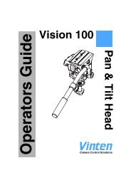
<strong>Vector</strong> <strong>950</strong> <strong>OE</strong><br />
<strong>Pan</strong> <strong>and</strong> <strong>Tilt</strong> <strong>Head</strong><br />
Publication Part No. V3984-4980<br />
Issue 1 (February 2008)<br />
English . . . . . . . . . . . . . . . . . . . . Page 7<br />
Deutsch. . . . . . . . . . . . . . . . . . . Seite 29<br />
Español. . . . . . . . . . . . . . . . . Página 51<br />
Français . . . . . . . . . . . . . . . . . . Page 73<br />
Italiano . . . . . . . . . . . . . . . . . Pagina 95<br />
Português . . . . . . . . . . . . . . Página 117<br />
. . . . . . . . . . . . . . . . . . 139<br />
. . . . . . . . . . . . . . . . . . . . . . . 161<br />
Copyright © Vitec Group plc 2008<br />
All rights reserved throughout the world. No part of this document may be stored in a retrieval system,<br />
transmitted, copied or reproduced in any way including, but not limited to, photocopy, photograph,<br />
magnetic or other record without the prior agreement <strong>and</strong> permission in writing of<br />
Vitec Group plc.<br />
<strong>Vinten</strong>®, <strong>Vector</strong>® <strong>and</strong> Quickfix® are registered trademarks of Vitec Group plc.<br />
Printed in Great Britain by DPS, Newmarket, Suffolk.
Underst<strong>and</strong>ing these instructions<br />
English<br />
The original instructions presented in this operators guide were written in English, <strong>and</strong><br />
subsequently translated into other languages. If you are unable to underst<strong>and</strong> these<br />
instructions, contact <strong>Vinten</strong> or your distributor to obtain a translation of the original instructions<br />
(EU Countries).<br />
<br />
, ,<br />
, - . <br />
, <strong>Vinten</strong> , <br />
( ).<br />
esky<br />
Pokyny uvedené v této operátorské píruce byly pvodn napsány anglicky a následn byly<br />
pelo_eny do ostatních jazyk. Nerozumíte-li tmto pokynm, kontaktujte spolenost <strong>Vinten</strong><br />
nebo svého distributora, abyste získali peklad originálních pokyn (lenské státy EU).<br />
Danish<br />
De originale instruktioner, der præsenteres i denne betjeningsvejledning, er skrevet på engelsk<br />
og derefter oversat til <strong>and</strong>re sprog. Hvis du ikke forstår disse instruktioner bedes du kontakte<br />
<strong>Vinten</strong> eller vor forh<strong>and</strong>ler for at få en oversættelse af de originale instruktioner (EU-l<strong>and</strong>e).<br />
Deutsch<br />
Die Originalanleitung in diesem Bedienungsh<strong>and</strong>buch wurde auf Englisch verfasst und<br />
anschließend in <strong>and</strong>ere Sprachen übersetzt. Bei Verständnisproblemen in einer der übersetzten<br />
Sprachen kontaktieren Sie bitte <strong>Vinten</strong> oder Ihren Fachhändler; dort erhalten Sie eine<br />
Übersetzung der ursprünglichen Anleitung (EU-Staaten).<br />
Eesti<br />
Käesoleva kasutajajuhendi algtekst on koostatud inglise keeles ning seejärel tõlgitud teistesse<br />
keeltesse. Kui juhend osutub teie jaoks arusaamatuks, võtke juhendi emakeelse tõlke<br />
hankimiseks ühendust <strong>Vinten</strong>i või kohaliku esindajaga (Euroopa Liidu riigid).<br />
<br />
<br />
. <br />
, <strong>Vinten</strong> <br />
( ).<br />
Español<br />
Las instrucciones originales que se indican en esta guía del operador se han redactado en<br />
inglés y posteriormente se han traducido a otros idiomas. Si no entiende estas instrucciones,<br />
póngase en contacto con <strong>Vinten</strong> o con su distribuidor para obtener una traducción de las<br />
instrucciones originales (para países de la UE).<br />
Français<br />
Les instructions originales présentées dans ce guide d'utilisation ont été écrites en anglais puis<br />
traduites dans d'autres langues. Si vous ne comprenez pas ces instructions, contactez <strong>Vinten</strong><br />
ou votre revendeur pour obtenir une traduction des instructions originales (pour les pays de<br />
l'UE).<br />
3
Gaeilge<br />
Scríobhadh na treoracha bunaidh don treoirleabhar oibritheora seo as Béarla, agus aistríodh iad<br />
go teangacha eile ina dhiaidh sin. Mura bhfuil tú in ann na treoracha seo a thuiscint, téigh i<br />
dteagmháil le <strong>Vinten</strong> nó le do dháileoir, chun aistriúchán de na treoracha bunaidh a fháil (Tíortha<br />
an AE).<br />
Italiano<br />
Le istruzioni originali presentate in questa guida per l'operatore sono in lingua inglese e<br />
successivamente tradotte nelle altre lingue. Qualora le istruzioni non fossero disponibili nella<br />
lingua desiderata, potete contattare <strong>Vinten</strong> o il vostro distributore per ricevere la traduzione delle<br />
istruzioni originali (Paesi UE).<br />
Latviešu<br />
Šaj operatora rokasgrmat iekautie nordjumi skotnji tika sarakstti angu valod un pc<br />
tam prtulkoti cits valods. Ja nesaprotat šos nordjumus svešvalod, sazinieties ar <strong>Vinten</strong><br />
vai tirgotju, lai saemtu nordjumu tulkojumu (kd no ES dalbvalstu valodm).<br />
Lietuvi<br />
Šiame operatoriaus vadove pristatomos pirmins instrukcijos parašytos angl kalba ir vliau<br />
išverstos kitas kalbas. Jei ši instrukcij nesuprantate, susisiekite su „<strong>Vinten</strong>“ arba savo<br />
platintoju ir gaukite pirmini instrukcij vertim (ES šalies kalba).<br />
Magyar<br />
A kezeloi útmutatóban található utasítások angol nyelven íródtak, és utólag fordították azokat<br />
más nyelvekre. Ha nem érti ezen utasításokat, kérjük, vegye fel a kapcsolatot a <strong>Vinten</strong>nel vagy<br />
a helyi képviselettel, és igényelje az eredeti utasítások fordítását (EU országok).<br />
Malti<br />
L-istruzzjonijiet originali ippreentati f'din il-gwida ta' operaturi kienu miktuba bl-Ingli, u<br />
sussegwentement maqluba fl-lingwi ohra. Jekk ma tistax tifhem dawn l-istruzzjonijiet, ikkuntattja<br />
lil <strong>Vinten</strong> jew id-distributur tieghek biex tikseb traduzzjoni ta' l-istruzzjonijiet originali (Pajjii ta'<br />
UE).<br />
Nederl<strong>and</strong>s<br />
De oorspronkelijke instructies in deze bedieningsh<strong>and</strong>leiding zijn geschreven in het Engels en<br />
vervolgens in <strong>and</strong>ere talen vertaald. Als het onmogelijk is deze instructies te begrijpen, neemt u<br />
contact op met <strong>Vinten</strong> of met uw distributeur om een vertaling te bemachtigen van de<br />
oorspronkelijke instructies (EG-l<strong>and</strong>en).<br />
Polski<br />
Oryginalne instrukcje zamieszczone w niniejszym podrczniku operatora zostay napisane w<br />
jzyku angielskim, a nastpnie przetumaczone na inne jzyki. Jeli nie rozumiej Pastwo tych<br />
instrukcji, prosimy skontaktowa si z siedzib lub dystrybutorem <strong>Vinten</strong>, aby uzyska<br />
tumaczenie oryginalnych instrukcji (kraje UE).<br />
Português<br />
As instruções originais apresentadas no guia do operador foram escritas em Inglês e traduzidas<br />
para outros idiomas. Se não conseguir compreender estas instruções contacte a <strong>Vinten</strong> ou o<br />
seu distribuidor para obter a tradução das instruções originais (Países da UE).<br />
4
Român<br />
Instruciunile originale prezentate în acest ghid pentru operatori au fost scrise în limba englez,<br />
i traduse ulterior în alte limbi. În cazul în care nu înelegei aceste instruciuni, contactai <strong>Vinten</strong><br />
sau distribuitorul dumneavoastr pentru a obine o traducere a instruciunilor originale (rile<br />
UE).<br />
Slovensky<br />
Pôvodné pokyny, uvedené v tomto návode na obsluhu, boli napísané v anglictine a následne<br />
preložené do iných jazykov. Ak nerozumiete týmto pokynom, obrátte sa na spolocnost <strong>Vinten</strong><br />
alebo vášho distribútora, aby vám zaslal preklad originálnych pokynov (krajiny EÚ).<br />
Slovenšina<br />
Originalno besedilo teh navodil za uporabo je bilo napisano v anglešini in prevedeno v ostale<br />
jezike. e ne razumete teh navodil, se obrnite na podjetje <strong>Vinten</strong> ali lokalnega zastopnika, ki<br />
vam bo posredoval originalna navodila (velja za dr_ave EU).<br />
Suomi<br />
Tähän käyttäjän oppaaseen sisältyvät ohjeet on kirjoitettu alun perin englanniksi ja käännetty<br />
sitten muille kielille. Ellet ymmärrä näitä ohjeita, ota yhteyttä <strong>Vinten</strong>iin tai jälleenmyyjään ja<br />
pyydä alkuperäisten ohjeiden käännöstä (EU-maat).<br />
Svenska<br />
Instruktionerna i denna h<strong>and</strong>bok skrevs ursprungligen på engelska och har sedan översatts till<br />
flera språk. Om du inte förstår dessa instruktioner, kontakta <strong>Vinten</strong> eller din återförsäljare för en<br />
ny översättning av originalinstruktionerna (EU-länder).<br />
5
Preface<br />
English<br />
Thank you <strong>and</strong> congratulations on your new <strong>Vector</strong> <strong>950</strong> <strong>OE</strong><br />
from <strong>Vinten</strong><br />
We want you to get the most from your new <strong>Vector</strong> <strong>950</strong> <strong>OE</strong>, <strong>and</strong> therefore encourage you to read this operators<br />
guide to familiarise yourself with its many features, some of which may be new to you. It also covers<br />
essential health <strong>and</strong> safety information <strong>and</strong> a section on maintenance that will ensure you keep your new<br />
product in perfect condition.<br />
To receive additional benefits, register with <strong>Vinten</strong> now, on line by visiting www.vinten.com, or by completing<br />
the enclosed form.<br />
Features <strong>and</strong> benefits of your new <strong>Vector</strong> <strong>950</strong> <strong>OE</strong><br />
The <strong>Vector</strong> <strong>950</strong> <strong>OE</strong> has been specifically designed to meet the exacting dem<strong>and</strong>s of camera operators<br />
working with full facility studio <strong>and</strong> OB cameras. The <strong>Vector</strong> <strong>950</strong> <strong>OE</strong> offers a high level of control with many<br />
unique features.<br />
• Suitable for a wide range of cameras, from 16-120 kg (35-264.5 lb) at 150 mm (6 in.) C of G <strong>and</strong><br />
supplied with a wedge adaptor.<br />
• The unique Perfect Balance system provides infinite adjustment, enabling you to achieve<br />
perfect camera balance throughout the tilt range, regardless of drag setting.<br />
• A retractable adjuster provides extensive camera fore <strong>and</strong> aft movement so that you can position<br />
the camera easily <strong>and</strong> perfectly.<br />
• The digital counterbalance display provides an LCD numerical display, indicating the level of<br />
counterbalance chosen to balance the camera. This is particularly useful if you regularly<br />
change your camera, lens, viewfinder or battery combination, as you can quickly 'dial in' the<br />
number that suits that particular combination.<br />
• You can keep up with the action as it happens with the responsive TF Drag control. It provides<br />
a wide range of infinitely adjustable, frictionless drag from very light to extremely<br />
heavy, suitable for operating conditions down to - 40°C <strong>and</strong> up to + 60°C. The TF drag system<br />
also allows you to pan extremely quickly or “whip pan” from one position to another, recovering<br />
instantly without any spring back.<br />
• You can set up easily in low light conditions using the illuminated level bubble <strong>and</strong> back-lit<br />
display.<br />
• Easy to carry, with an integral, fold-away h<strong>and</strong>le.<br />
• High resolution pan <strong>and</strong> tilt encoder output<br />
Once again, thank you for choosing the <strong>Vector</strong> <strong>950</strong> <strong>OE</strong>.<br />
We are confident it will give you many years of reliable<br />
performance.<br />
Register your product to get One Extra Years Warranty <strong>and</strong> a<br />
Free <strong>Vinten</strong> Quality Gift.<br />
Please register now on-line at www.vinten.com/register—it's easy <strong>and</strong> fast.<br />
Warranty Details <strong>and</strong> Terms <strong>and</strong> Conditions can be found on page 26.<br />
7
English<br />
Safety - read this first<br />
English—Original Instructions<br />
The original instructions presented in this operators guide were written in English, <strong>and</strong> subsequently translated<br />
into other languages. If you are unable to underst<strong>and</strong> any of the translated languages, contact <strong>Vinten</strong><br />
or your distributor to obtain a translation of the original instructions (EU Countries).<br />
Warning Symbols in this Operators Guide<br />
Where there is a risk of personal injury or injury to others, comments appear highlighted<br />
by the word WARNING!—supported by the warning triangle symbol.<br />
Where there is a risk of damage to the product, associated equipment, process or<br />
surroundings, comments appear highlighted by the word CAUTION!<br />
Warning symbols on the product<br />
On encountering the warning triangle<br />
<strong>and</strong> open book symbols it is imperative<br />
that you consult this<br />
operators guide before using this<br />
product or attempting any adjustment<br />
or repair.<br />
Where there is a risk of electric<br />
shock, comments appear supported<br />
by the hazardous voltage warning<br />
triangle symbol.<br />
Regulatory information<br />
This product conforms to the following European Directive:<br />
2004/108/EC (Electromagnetic Compatibility Directive)<br />
Compliance with this directive implies conformity to the following European st<strong>and</strong>ards:<br />
EN 55103-1: Electromagnetic Interference (Emission)<br />
EN 55103-2: Electromagnetic Susceptibility (Immunity)<br />
This product is intended for the following Electromagnetic Environment:<br />
E4 controlled EMC environment, including TV studios.<br />
FCC:<br />
CFR 47:2006 Class A<br />
8
WEEE directive<br />
English<br />
WEEE Directive 2002/96/EC m<strong>and</strong>ates the treatment, recovery <strong>and</strong> recycling of electric<br />
<strong>and</strong> electronic equipment. This product is subject to WEEE disposal regulations. Please<br />
visit www.vinten.com/recycle for details.<br />
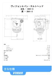
Technical data<br />
Weight (including wedge adaptor <strong>and</strong> telescopic pan bar)<br />
17.6 kg (38.8 lb)<br />
Height to wedge adaptor mounting face<br />
24.8 cm (11.3 in.)<br />
Length<br />
22.5 cm (8.9 in.)<br />
Width<br />
34.2 cm (13.5 in.)<br />
Typical payload 16-120 kg (35-264.5 lb) - See balance graph (Fig 3)<br />
<strong>Tilt</strong> range 60 kg payload to ±90°, 120 kg payload to ±60°<br />
<strong>Pan</strong> range 360°<br />
<strong>Tilt</strong> encoder resolution 2,207,598 counts per 360°<br />
<strong>Pan</strong> encoder resolution 2,000,723 counts per 360°<br />
Supported protocols<br />
RS232/RS422<br />
External power requirements<br />
12V dc (supplied from Active Serial Box)<br />
Internal power requirement - axis encoders<br />
5 V dc ±5% 120 mA<br />
Operating temperature range<br />
- 40°C to + 60°C (- 40°F to + 140°F)<br />
Maximum operating humidity<br />
< 80% RH<br />
Pedestal/tripod fixing Four-hole flat base<br />
`Quickfix' adaptor<br />
Mitchell adaptor<br />
Usage<br />
The <strong>Vector</strong> <strong>950</strong> <strong>OE</strong> pan <strong>and</strong> tilt head is designed for use in television studios <strong>and</strong> on location to support<br />
<strong>and</strong> balance a camera <strong>and</strong> ancillary equipment weighing up to 120 kg (264.5 lb), <strong>and</strong> to provide digital positional<br />
output for <strong>Vinten</strong> Active systems. This product is intended for use by television camera operators.<br />
9
English<br />
WARNING!<br />
1. Do NOT attempt to use this product if you do not underst<strong>and</strong> how to<br />
operate it.<br />
2. Do NOT use this product for any other purpose than that specified in the<br />
Usage statement above.<br />
3. Maintenance beyond that detailed in this Operators Guide must be performed<br />
only by competent personnel in accordance with the procedures<br />
laid down in the Maintenance Manual.<br />
Further information<br />
For further information or advice regarding this pan <strong>and</strong> tilt head, please contact <strong>Vinten</strong>, your local <strong>Vinten</strong><br />
distributor (see back cover) or visit our website.<br />
For details on maintenance <strong>and</strong> spare parts, please refer to the <strong>Vector</strong> <strong>950</strong> <strong>OE</strong> <strong>Pan</strong> <strong>and</strong> <strong>Tilt</strong> <strong>Head</strong> Maintenance<br />
Manual <strong>and</strong> Illustrated Parts List (Publication Part No. V3984-4990) This is obtainable from <strong>Vinten</strong><br />
or your local <strong>Vinten</strong> distributor. For information on-line, visit our website at<br />
www.vinten.com<br />
10
Contents<br />
English<br />
Page<br />
Preface . . . . . . . . . . . . . . . . . . . . . . . . . . . . . . . . . . . . . . . . . . . . . . . . . . . . . . . . . . 7<br />
Safety - read this first . . . . . . . . . . . . . . . . . . . . . . . . . . . . . . . . . . . . . . . . . . . . . . 8<br />
Technical data . . . . . . . . . . . . . . . . . . . . . . . . . . . . . . . . . . . . . . . . . . . . . . . . . . . . 9<br />
Further information . . . . . . . . . . . . . . . . . . . . . . . . . . . . . . . . . . . . . . . . . . . . . . . 10<br />
Introduction<br />
Perfect balance . . . . . . . . . . . . . . . . . . . . . . . . . . . . . . . . . . . . . . . . . . . . . . . . . 15<br />
TF drag . . . . . . . . . . . . . . . . . . . . . . . . . . . . . . . . . . . . . . . . . . . . . . . . . . . . . . . 15<br />
<strong>Pan</strong> <strong>and</strong> tilt brakes. . . . . . . . . . . . . . . . . . . . . . . . . . . . . . . . . . . . . . . . . . . . . . . 15<br />
Centre lock . . . . . . . . . . . . . . . . . . . . . . . . . . . . . . . . . . . . . . . . . . . . . . . . . . . . 15<br />
Illuminated level bubble. . . . . . . . . . . . . . . . . . . . . . . . . . . . . . . . . . . . . . . . . . . 15<br />
<strong>Pan</strong> bar . . . . . . . . . . . . . . . . . . . . . . . . . . . . . . . . . . . . . . . . . . . . . . . . . . . . . . . 15<br />
Wedge adaptor . . . . . . . . . . . . . . . . . . . . . . . . . . . . . . . . . . . . . . . . . . . . . . . . . 16<br />
Four-hole mounting plate . . . . . . . . . . . . . . . . . . . . . . . . . . . . . . . . . . . . . . . . . 16<br />
Carrying h<strong>and</strong>le. . . . . . . . . . . . . . . . . . . . . . . . . . . . . . . . . . . . . . . . . . . . . . . . . 16<br />
Positioning encoders. . . . . . . . . . . . . . . . . . . . . . . . . . . . . . . . . . . . . . . . . . . . . 16<br />
Electronic unit . . . . . . . . . . . . . . . . . . . . . . . . . . . . . . . . . . . . . . . . . . . . . . . . . . 16<br />
Operation<br />
Installing the head. . . . . . . . . . . . . . . . . . . . . . . . . . . . . . . . . . . . . . . . . . . . . . . 17<br />
<strong>Pan</strong> bars . . . . . . . . . . . . . . . . . . . . . . . . . . . . . . . . . . . . . . . . . . . . . . . . . . . . . . 17<br />
Fitting a camera . . . . . . . . . . . . . . . . . . . . . . . . . . . . . . . . . . . . . . . . . . . . . . . . 17<br />
Connecting the head. . . . . . . . . . . . . . . . . . . . . . . . . . . . . . . . . . . . . . . . . . . . . 18<br />
Stability . . . . . . . . . . . . . . . . . . . . . . . . . . . . . . . . . . . . . . . . . . . . . . . . . . . . . . . 18<br />
Balancing the head . . . . . . . . . . . . . . . . . . . . . . . . . . . . . . . . . . . . . . . . . . . . . . 18<br />
Locking the platform . . . . . . . . . . . . . . . . . . . . . . . . . . . . . . . . . . . . . . . . . . . . . 20<br />
<strong>Pan</strong> <strong>and</strong> tilt brakes. . . . . . . . . . . . . . . . . . . . . . . . . . . . . . . . . . . . . . . . . . . . . . . 20<br />
<strong>Pan</strong> <strong>and</strong> tilt drag . . . . . . . . . . . . . . . . . . . . . . . . . . . . . . . . . . . . . . . . . . . . . . . . 20<br />
<strong>Pan</strong> <strong>and</strong> tilt drag . . . . . . . . . . . . . . . . . . . . . . . . . . . . . . . . . . . . . . . . . . . . . . . . 20<br />
Servicing<br />
General . . . . . . . . . . . . . . . . . . . . . . . . . . . . . . . . . . . . . . . . . . . . . . . . . . . . . . . 22<br />
Routine maintenance . . . . . . . . . . . . . . . . . . . . . . . . . . . . . . . . . . . . . . . . . . . . 22<br />
Cleaning . . . . . . . . . . . . . . . . . . . . . . . . . . . . . . . . . . . . . . . . . . . . . . . . . . . . . . 22<br />
Electronic unit battery replacement. . . . . . . . . . . . . . . . . . . . . . . . . . . . . . . . . . 22<br />
Balance mechanism digital display calibration . . . . . . . . . . . . . . . . . . . . . . . . . 23<br />
Adjustments . . . . . . . . . . . . . . . . . . . . . . . . . . . . . . . . . . . . . . . . . . . . . . . . . . . 23<br />
Repositioning the wedge adaptor . . . . . . . . . . . . . . . . . . . . . . . . . . . . . . . . 23<br />
Platform slide clamp adjustment . . . . . . . . . . . . . . . . . . . . . . . . . . . . . . . . . 24<br />
<strong>Pan</strong> <strong>and</strong> tilt brake adjustment. . . . . . . . . . . . . . . . . . . . . . . . . . . . . . . . . . . . 24<br />
Parts List. . . . . . . . . . . . . . . . . . . . . . . . . . . . . . . . . . . . . . . . . . . . . . . . . . . . . . . . 25<br />
Warranty Details <strong>and</strong> Terms <strong>and</strong> Conditions. . . . . . . . . . . . . . . . . . . . . . . . . . . 26<br />
Figures . . . . . . . . . . . . . . . . . . . . . . . . . . . . . . . . . . . . . . . . . . . . . . . . . . . . . . . . 175<br />
11
English<br />
Associated publication<br />
<strong>Vector</strong> <strong>950</strong> <strong>OE</strong> <strong>Pan</strong> <strong>and</strong> <strong>Tilt</strong> <strong>Head</strong><br />
Maintenance Manual<br />
Publication Part No. V3984-4990<br />
12
<strong>Vector</strong> <strong>950</strong> <strong>OE</strong> <strong>Pan</strong> <strong>and</strong> <strong>Tilt</strong> <strong>Head</strong><br />
(Right-H<strong>and</strong> Side)<br />
(Fig 1)<br />
English<br />
(1) Wedge adaptor operating lever<br />
(2) Sliding plate adjustment h<strong>and</strong>le<br />
(3) Carrying h<strong>and</strong>le<br />
(4) Centre lock plunger<br />
(5) Balance knob<br />
(6) <strong>Tilt</strong> brake lever<br />
(7) <strong>Pan</strong> brake lever<br />
(8) Centre lock release lever<br />
(9) Illuminated level bubble<br />
(10) Timer button<br />
(11) Digital display<br />
(12) Illumination button<br />
(13) Graduated sliding plate<br />
(14) Wedge adaptor<br />
(15) Wedge adaptor mounting screw<br />
<strong>Vector</strong> <strong>950</strong> <strong>OE</strong> <strong>Pan</strong> <strong>and</strong> <strong>Tilt</strong> <strong>Head</strong><br />
(Left-H<strong>and</strong> Side)<br />
(Fig 2)<br />
(16) Sliding plate clamp lever<br />
(17) <strong>Pan</strong> bar mounting<br />
(18) <strong>Tilt</strong> drag adjustment knob<br />
(19) <strong>Pan</strong> drag adjustment knob<br />
(20) Battery cover<br />
(21) Mitchell adaptor key way<br />
(22) Bracket mounting holes<br />
(23) <strong>Pan</strong> data indicator<br />
13
English<br />
(24) <strong>Tilt</strong> data indicator<br />
(25) Four-hole mounting plate<br />
(26) Encoder connector<br />
14
Introduction<br />
English<br />
The <strong>Vector</strong> <strong>950</strong> <strong>OE</strong> (Fig 1 <strong>and</strong> Fig 2) combines a manually-operated pan <strong>and</strong> tilt head with electronic encoders<br />
to provide precise real-time digital electronic positioning, which, when combined with an ‘Active’ Serial<br />
Box <strong>and</strong> an appropriate lens, greatly reduces unwanted image movement from a shot.<br />
The <strong>Vector</strong> <strong>950</strong> <strong>OE</strong> pan <strong>and</strong> tilt head also embodies a unique <strong>and</strong> patented spring counterbalancing mechanism,<br />
thin film (TF) drag assemblies for pan <strong>and</strong> tilt motions <strong>and</strong> an adjustable camera mounting plate.<br />
Perfect balance<br />
The spring counterbalancing mechanism comprises four springs operating against a three-dimensional<br />
cam connected to the camera mounting platform. The balance mechanism is adjusted by a knob (5), situated<br />
on the right front lower part of the main body, which varies the mechanical advantage between the<br />
cam <strong>and</strong> the springs. The knob has a ‘push in <strong>and</strong> turn’ action <strong>and</strong> is fitted with a clutch to prevent inadvertent<br />
damage to the balance mechanism.<br />
Maximum <strong>and</strong> minimum payloads that can be balanced, <strong>and</strong> tilt ranges, are dependent on the weight of<br />
the camera <strong>and</strong> accessories <strong>and</strong> on the centre of gravity (C of G) height.<br />
The graph (Fig 3) shows the range of load <strong>and</strong> C of G height that can be maintained in balance. The shaded<br />
area of graph corresponds to those load/C of G combinations that can be balanced over the full tilt range.<br />
The area to the right indicate the progressively reducing tilt range with greater load <strong>and</strong> higher<br />
C of G.<br />
Where a load/C of G combination falls outside of the graph it will be necessary to increase or decrease the<br />
weight or the C of G height - if possible - to enable the head to balance the load.<br />
A digital display (11) indicates the setting of the balance mechanism on a scale of 0-100. The display is<br />
active when the balance knob (5) is turned <strong>and</strong> extinguishes automatically approximately 15 seconds after<br />
adjustments are complete. The display may be lit by pressing the illumination button (12). The battery for<br />
the system is housed in a compartment in the base of the head, closed by a cover (20).<br />
TF drag<br />
Both the pan <strong>and</strong> tilt mechanisms incorporate the <strong>Vinten</strong> thin film (TF) system to ensure smooth movement<br />
of the camera about these axes <strong>and</strong> are fitted with control knobs (18), (19) to adjust the drag setting. The<br />
whip-pan facility is unaffected by the pan drag setting. Both drag knobs are provided with scales illuminated<br />
by the button (12). The lights will go out after approximately 15 seconds.<br />
<strong>Pan</strong> <strong>and</strong> tilt brakes<br />
Friction brakes on each axis allow the head to be locked at any chosen position. The operating levers for<br />
both brakes (6), (7) are located side-by-side on the right-h<strong>and</strong> side of the head.<br />
Centre lock<br />
A centre lock (4) allows the head to be locked in the horizontal position.<br />
Illuminated level bubble<br />
A level bubble (9), illuminated by pressing the illumination button (12), is fitted to the rear of the head. The<br />
same button also illuminates the pan <strong>and</strong> tilt drag knob scales <strong>and</strong> the LCD display. The light will go out<br />
after approximately 15 seconds.<br />
<strong>Pan</strong> bar<br />
<strong>Pan</strong> bar mounting points (17) are located at the rear of the head, on either side of the camera mounting<br />
platform. A telescopic pan bar is supplied <strong>and</strong> is attached using a pan bar clamp, with angular adjustment<br />
available on the mount serrations. A second pan bar may be fitted.<br />
15
English<br />
Wedge adaptor<br />
The camera is attached to the head by means of a wedge adaptor (14), which is mounted on a graduated<br />
sliding plate (13). The position of the slide plate is adjusted by a retractable knob (2) <strong>and</strong> a clamp (16) is<br />
provided to hold the slide plate in position.<br />
Four-hole mounting plate<br />
The head is provided with a st<strong>and</strong>ard <strong>Vinten</strong> four-hole mounting plate (25), which includes a `Quickfix'<br />
mounting <strong>and</strong> provision for use of a Mitchell adaptor (21).<br />
Carrying h<strong>and</strong>le<br />
A retractable carrying h<strong>and</strong>le (3) is provided on the right-h<strong>and</strong> side of the head. The h<strong>and</strong>le is spring-loaded<br />
to the closed position.<br />
Positioning encoders<br />
The <strong>Vector</strong> <strong>950</strong> <strong>OE</strong> head is fitted with high resolution Renishaw encoders on both pan <strong>and</strong> tilt axes, which<br />
are accessed via a connector (26) on the left-h<strong>and</strong> side of the head. The quadrature square wave outputs<br />
provide high-resolution real-time digital output of 1,900,000 counts for 360° of pan <strong>and</strong> 2,200,000 counts<br />
for 360° of tilt.<br />
Electronic unit<br />
An electronic unit is fitted to the rear of the head, powered by a battery housed in a compartment (20) in<br />
the base of the head. The unit comprises a two-row digital display (11) <strong>and</strong> two push-button buttons - an<br />
illumination button (12), which illuminates the LCD display, levelling bubble <strong>and</strong> the pan <strong>and</strong> tilt drag knob<br />
scales for 15 seconds, <strong>and</strong> a timer button (10). Pressed singly or in conjunction with each other, the buttons<br />
provide control of the time, stopwatch <strong>and</strong> calibration functions.<br />
For a detailed description of each function, see Digital display on page 20.<br />
16
Operation<br />
English<br />
Installing the head<br />
WARNING!<br />
1. DO NOT use shackles when using lifting equipment to raise or lower the<br />
head. Use slings or straps.<br />
2. DO NOT attach lifting slings or straps to the carrying h<strong>and</strong>le.<br />
3. Ensure that slings or straps are securely attached to the head.<br />
A suitable lifting point is located at the rear of the platform, accessed by<br />
moving the sliding plate (13) to the fully forward position.<br />
4. Only install the head onto a tripod or pedestal which is capable of supporting<br />
the mass of the head <strong>and</strong> it’s full payload.<br />
The <strong>Vector</strong> <strong>950</strong> <strong>OE</strong> head may be installed on a st<strong>and</strong>ard ‘<strong>Vinten</strong>’ tripod or pedestal using the four mounting<br />
bolts <strong>and</strong> washers provided or by using a `Quickfix' adaptor.<br />
Adaptors are available which enable the heads to be installed on tripods or pedestals fitted with other<br />
mountings. These are listed in the Parts List under Optional accessories on page 25.<br />
CAUTION! Fixing bolts that are too long will not clamp adequately.<br />
Before installing the head, hold a fixing bolt in position <strong>and</strong> check that the threaded<br />
end does not project more than 12 mm (15/32 in.) above the mounting face.<br />
After mounting the head on a tripod, use the level bubble (9) to set it level. The level bubble may be illuminated<br />
by pressing the illumination button (12). The light will go out after approximately 15 seconds.<br />
<strong>Pan</strong> bars<br />
Fit the pan bars on the mountings (17) <strong>and</strong> adjust the position of each one before tightening the clamps.<br />
Adjust the length of the telescopic pan bar. Optional fixed <strong>and</strong> short fixed pan bars are available (see Main<br />
assemblies in the Parts List on page 25).<br />
Fitting a camera<br />
WARNING!<br />
1. DO NOT rely on the tilt brake when changing the payload. Always engage<br />
the centre lock.<br />
2. Ensure that the weight <strong>and</strong> C of G height of the total payload is within the<br />
range for which the head is designed.<br />
3. If installing the camera to a pedestal mounted pan <strong>and</strong> tilt head, fully<br />
depress the pedestal column before installing the camera.<br />
To fit a camera, proceed as follows:<br />
If not already fitted, install the wedge adaptor (14) in the middle position on the sliding plate (13)<br />
(see Servicing on page 22).<br />
Attach the wedge to the camera/lens.<br />
Ensure that the centre lock (4) is engaged (see Locking the platform on page 20).<br />
17
English<br />
Slide the wedge adaptor operating lever (1) forward (parallel to the wedge) about 6 mm (1/4 in.)<br />
against spring tension. Pull the operating lever out, away from the body of the wedge adaptor, as<br />
far as it will go.<br />
Insert the camera wedge into the wedge adaptor <strong>and</strong> push it forward into full engagement. Push in<br />
the operating lever (1) until it lies parallel with the wedge adaptor body. During this operation resistance<br />
of the spring-loaded over-centre mechanism will be felt. As the lever reaches the end of<br />
its travel it will slide back (parallel to the wedge) to the locked position.<br />
Confirm that the lever is in the locked position. This is indicated by coloured b<strong>and</strong>s above the lever.<br />
When the green b<strong>and</strong> only is visible, the lever is locked. If any of the red b<strong>and</strong> can be seen, the<br />
lever is not locked.<br />
Install the remainder of the payload (lens, zoom <strong>and</strong> focus controls, viewfinder, prompter etc.).<br />
Connecting the head<br />
The encoder connector (26) connects directly to the ‘Active Serial Box’ which attaches to the mounting<br />
holes (22) on the underside of the head. For more information refer to the Active Serial Box Operators<br />
Guide (Publication Part No. V4039-4980).<br />
<strong>Pan</strong>(23) <strong>and</strong> tilt (24) axis data indicators illuminate when an Active Serial Box is connected <strong>and</strong> switched<br />
on, signifying the axis encoders are powered <strong>and</strong> providing output data.<br />
Stability<br />
When mounting the pan <strong>and</strong> tilt head on a tripod, it is possible to set the tripod legs so that the centre-ofgravity<br />
of the tilted payload falls outside of the footprint of the tripod, leading to instability.<br />
WARNING!<br />
1. Always use a mid-level or floor spreader to ensure that the tripod legs<br />
are spread sufficiently so that the centre-of-gravity of the tilted payload<br />
remains within the footprint of the tripod.<br />
Balancing the head<br />
2. Where possible, use the tie-down hook on the tripod for additional stability.<br />
NOTE: It is important that the pan bar(s) <strong>and</strong> all camera accessories (lens, zoom <strong>and</strong> focus<br />
controls, viewfinder, prompter etc.) are fitted in their operational position <strong>and</strong> the system<br />
connected before balancing the head. Any equipment fitted or adjusted later will<br />
unbalance the head.<br />
Balancing the <strong>Vector</strong> <strong>950</strong> <strong>OE</strong> head achieves two objectives. Firstly, when a head is correctly balanced the<br />
operator will need a minimum amount of even effort to move the head. Secondly, once balanced, the head<br />
<strong>and</strong> its payload can be set to any tilt position <strong>and</strong> the head will maintain this position with ‘h<strong>and</strong>s off’.<br />
The graph (Fig 3) shows the range of load <strong>and</strong> C of G height that can be maintained in balance. The shaded<br />
area of graph corresponds to those load/C of G combinations that can be balanced over the full tilt range.<br />
The area to the right indicate the progressively reducing tilt range with greater load <strong>and</strong> higher<br />
C of G.<br />
Fore <strong>and</strong> aft balance<br />
When positioning the payload it is important to be aware of the potential danger of an unbalanced payload<br />
falling away suddenly. Before disengaging the centre lock, set the balance adjustment knob (5) to its mid<br />
point setting (50 on the digital display). Depending on the payload weight, it may be necessary to increase<br />
or decrease this setting to enable the payload to be correctly balanced fore <strong>and</strong> aft.<br />
Balance the payload fore <strong>and</strong> aft as follows:<br />
18
English<br />
Ensure that the centre lock is engaged (see Locking the platform on page 20) <strong>and</strong> that the camera<br />
<strong>and</strong> all accessories are fitted.<br />
Turn the tilt drag adjustment knob (18) to minimum.<br />
Push in <strong>and</strong> turn the balance adjustment knob (5) to its mid point setting.<br />
WARNING!<br />
Be prepared to prevent the head falling away suddenly when disengaging<br />
the centre lock. In the event of the head falling away violently, increase the<br />
setting on the balance adjustment knob (5).<br />
Holding the pan bar to steady the platform, disengage the centre lock (see Locking the platform<br />
on page 20).<br />
Release the sliding plate clamp (16) <strong>and</strong> pull out the sliding plate adjustment knob (2) until it engages<br />
with the platform drive. Turn the knob to move the sliding plate fore <strong>and</strong> aft to achieve horizontal<br />
balance.<br />
NOTE: The sliding plate is graduated to facilitate balancing. If the balance setting of the payload<br />
is known, turn the knob until that setting is reached.<br />
The horizontal balance is correct when no perceptible tilting force can be felt on the pan bar with<br />
the platform level. Apply the sliding plate clamp (16) <strong>and</strong> push in the adjustment knob (2) to its<br />
stowed position.<br />
If there is insufficient movement in the sliding plate to achieve balance, reposition the wedge adaptor<br />
(see Repositioning the wedge adaptor on page 23), refit the load <strong>and</strong> repeat the horizontal<br />
balancing procedure.<br />
The sliding plate is graduated. Make a note of the position to facilitate rebalancing this particular<br />
payload.<br />
Payload weight <strong>and</strong> C of G height adjustment<br />
When fore <strong>and</strong> aft balance has been achieved, carry out the payload weight <strong>and</strong> C of G height adjustment<br />
as follows:<br />
NOTE: If the digital balance setting of the payload is known, push in <strong>and</strong> turn the balance knob<br />
(5) until the digital display (11) shows that setting.<br />
Using the pan bar, tilt the platform forward <strong>and</strong> backward. When correctly balanced, there should<br />
be no perceptible tilting force on the pan bar at any angle of tilt <strong>and</strong> the head should remain in any<br />
tilt position to which it is set.<br />
NOTE: Setting the platform level will facilitate adjusting the balance setting<br />
If the head tends to fall away when the platform is tilted, set the platform level <strong>and</strong> push in <strong>and</strong> turn<br />
the balance adjustment knob (5) clockwise to increase the balance setting. If the head tends to<br />
spring back to centre, set the platform level <strong>and</strong> push in <strong>and</strong> turn the balance adjustment knob (5)<br />
counter-clockwise to decrease the balance setting.<br />
When the payload weight <strong>and</strong> C of G height adjustment is complete, check that the fore <strong>and</strong> aft<br />
balance remains satisfactory. Re-adjust the position of the sliding plate if necessary.<br />
The digital display (11) will display the balance setting while balance is being adjusted. Make a note<br />
of the final setting to facilitate rebalancing this particular payload.<br />
After balancing, exercise the head through both axes to confirm that it operates smoothly.<br />
19
English<br />
Locking the platform<br />
The centre lock mechanism is operated by a plunger on the right-h<strong>and</strong> side of the head. To engage the<br />
lock, hold the platform in the horizontal position <strong>and</strong> push the plunger (4) inwards until it latches <strong>and</strong> the<br />
release lever (8) appears. Use the pan bar to rock the platform slightly whilst pushing the button.<br />
To release the centre lock, rock the platform slightly <strong>and</strong> push down on the release lever (8).<br />
<strong>Pan</strong> <strong>and</strong> tilt brakes<br />
The pan (7) <strong>and</strong> tilt brakes (6) are operated by levers on the right of the head. The brakes are applied by<br />
pushing the appropriate lever down <strong>and</strong> released by pulling the lever up.<br />
The brakes should be applied whenever the camera is left unattended.<br />
<strong>Pan</strong> <strong>and</strong> tilt drag<br />
Both the pan <strong>and</strong> tilt mechanisms incorporate the <strong>Vinten</strong> thin film (TF) system to ensure smooth movement<br />
of the camera about these axes <strong>and</strong> are fitted with control knobs to adjust the drag setting.<br />
Both drag knobs (18), (19) are provided with illuminated scales, graduated from 0 to 9. To illuminate the<br />
scales, press the button (12). The light will go out after approximately 15 seconds.<br />
The drag adjustment knobs are mounted on the left-h<strong>and</strong> side of the head. The smaller pan drag knob (19)<br />
is on the front lower part of the main body, with the larger tilt drag knob (18) in the centre on the tilt drag<br />
housing.<br />
To increase drag, turn the knob clockwise, towards a higher graduation. To decrease drag, turn the knob<br />
anti-clockwise, towards a lower graduation.The whip-pan facility is unaffected by the pan drag setting.<br />
Digital display<br />
(Fig 4)<br />
The digital display (11) comprises a two-row LCD display. It has three modes of operation, selected by the<br />
buttons (10), (12). The display may be illuminated by pressing the illumination button (12).<br />
Clock <strong>and</strong> stopwatch<br />
The top row of the display is a 24-hour clock (11.1), which is always visible. This is the default mode. The<br />
bottom row is a stopwatch, counting in seconds <strong>and</strong> minutes from 00:00 to 59:59.<br />
To set the clock:<br />
Press both buttons (10), (12) momentarily. The hours display will flash.<br />
Use the timer button (10) to increment the hours.<br />
Press the illumination button (12). The minutes display will flash.<br />
Use the timer button (10) to increment the minutes.<br />
Press the illumination button (12) to exit <strong>and</strong> start the clock.<br />
To display, start, stop or clear the stopwatch:<br />
Momentarily pressing the timer button (10) will display, start, stop or clear the stopwatch in that sequence.<br />
Balance<br />
Balance mode is active any time the balance adjustment knob (5) is turned (unless the stopwatch is running)<br />
<strong>and</strong> remains active for 15 seconds after adjustment has finished. In this mode the bottom row shows<br />
the setting of the balance mechanism on a scale of 0.0 to 100.0 The BAL legend (11.3) is also lit. The top<br />
row of the display shows the 24-hour clock.<br />
20
Calibration<br />
English<br />
This mode allows the balance display to be calibrated (see Balance mechanism digital display calibration<br />
on page 23). It is activated by pressing <strong>and</strong> holding both buttons (10), (12) for five seconds.<br />
Low battery<br />
The low battery indicator (11.2) will flash whenever the battery requires replacement (see Electronic<br />
unit battery replacement on page 22).<br />
21
English<br />
Servicing<br />
General<br />
The <strong>Vector</strong> <strong>950</strong> <strong>OE</strong> pan <strong>and</strong> tilt head is robustly made to high engineering st<strong>and</strong>ards <strong>and</strong> little attention is<br />
required to maintain serviceability save regular cleaning.<br />
Refer to the appropriate section in the Maintenance Manual if any defect is apparent. Adjustments <strong>and</strong> repairs<br />
should be carried out only by a competent person.<br />
Routine maintenance<br />
Replace the electronic unit battery whenever the low battery indicator flashes.<br />
During use, check the following:<br />
Check the effectiveness of the pan <strong>and</strong> tilt brakes. Reset as necessary.<br />
Check the effectiveness of the slide plate clamp. Reset as necessary.<br />
Check the operation of the balance mechanism digital display <strong>and</strong> the illumination of the LCD, level<br />
bubble <strong>and</strong> drag knobs. Replace battery if necessary.<br />
No further routine maintenance is required.<br />
Cleaning<br />
During normal use the only cleaning required should be a regular wipe over with a lint-free cloth. Dirt accumulated<br />
during storage or periods of disuse may be removed with a semi-stiff brush. Particular attention<br />
should be paid to the wedge location faces of the wedge adaptor.<br />
WARNING!<br />
Disconnect the head encoder cable before cleaning the head, to prevent<br />
potential electric shock.<br />
CAUTION! Use only detergent-based cleaners.<br />
DO NOT use solvent- or oil-based cleaners, abrasives or wire brushes to remove<br />
accumulations of dirt as these damage the protective surfaces.<br />
Use out-of-doors under adverse conditions may require special attention <strong>and</strong> the head should be covered<br />
when not in use. Salt spray should be washed off using fresh water at the earliest opportunity. S<strong>and</strong> <strong>and</strong><br />
dirt act as an abrasive <strong>and</strong> should be removed using a semi-stiff brush or a vacuum cleaner.<br />
Electronic unit battery replacement<br />
(Fig 5)<br />
The battery powers the digital display <strong>and</strong> illuminates the LCD, the level bubble <strong>and</strong> the drag knob scales.<br />
The battery should be replaced whenever the low battery indicator flashes.<br />
NOTE: Removal of the battery will not affect the calibration of the balance mechanism display.<br />
Prise out the battery cover (20).<br />
Pull the battery (20.1) out of the battery compartment as far as the wiring will allow.<br />
22
English<br />
Pull the connector (20.2) off the terminals of the old battery <strong>and</strong> push it onto the terminals of the<br />
new battery (20.1).<br />
Install the battery (20.1) in the battery compartment, ensuring that the wiring is neatly stowed.<br />
Refit the battery cover (20).<br />
Press the illumination button (12) <strong>and</strong> ensure that the balance mechanism digital display (11), the<br />
level bubble (9) <strong>and</strong> drag knob scales (18), (19) are lit for approximately 15 seconds.<br />
Turn the balance knob (5) <strong>and</strong> ensure that the balance display (11) is active for approximately 15<br />
seconds.<br />
Reset the clock (see Clock <strong>and</strong> stopwatch on page 20).<br />
Balance mechanism digital display calibration<br />
(Fig 6)<br />
The digital display (11) indicates the setting of the balance mechanism on a scale of 0 (minimum setting)<br />
to 100 (maximum setting). In the unlikely event of this system requiring calibration, proceed as follows:<br />
NOTE: If more than five minutes is allowed to elapse before completion, the system will shut<br />
down <strong>and</strong> revert to its previous settings.<br />
Level the platform <strong>and</strong> apply centre lock (4).<br />
Press <strong>and</strong> hold both buttons (10), (12) until CAL is displayed on the top row of the display.<br />
Push in <strong>and</strong> turn the balance knob (5) counterclockwise until its minimum end stop is reached, then<br />
turn back two full turns. The bottom row of the display will flash 0.<br />
Press <strong>and</strong> release the timer button (10). The bottom row of the display will flash 100.<br />
Push in <strong>and</strong> turn the balance knob (5) clockwise until its maximum end stop is reached, then turn<br />
back two full turns.<br />
Press <strong>and</strong> release the timer button (10). Calibration is now complete <strong>and</strong> the display will revert to<br />
the default clock mode.<br />
After calibration, rebalance the head (see Balancing the head on page 18).<br />
Adjustments<br />
To enable the payload to be correctly balanced, the wedge adaptor may require repositioning.<br />
The following adjustments may be necessary after prolonged use:<br />
The platform slide clamp may require adjustment.<br />
The pan <strong>and</strong> tilt brakes may require adjustment.<br />
Repositioning the wedge adaptor<br />
(Fig 1)<br />
The wedge adaptor (14) is secured by four cap head screws (15) which pass through the wedge adaptor<br />
into the sliding plate (13). The wedge adaptor may be fitted in three positions.<br />
CAUTION! Overlong screws will prevent the sliding plate from operating. Always use the screws<br />
provided (M6 x 30 mm).<br />
To reposition the wedge adaptor:<br />
23
English<br />
Engage the centre lock (see Locking the platform on page 20) <strong>and</strong> remove the payload.<br />
Hold the body of the wedge adaptor (14) <strong>and</strong> use a 4 mm hexagon wrench to remove four securing<br />
screws (15).<br />
Reposition the wedge adaptor (14) on the sliding plate (13), ensuring that the narrow end of the<br />
wedge adaptor faces forwards<br />
Insert the four screws (15) in the holes in the wedge adaptor <strong>and</strong> tighten.<br />
Platform slide clamp adjustment<br />
(Fig 7)<br />
The platform slide clamp should be set so that, in the up or clamped position it prevents the platform slide<br />
from being moved, while in the down or released position it allows free adjustment of the slide. To adjust<br />
the clamp, proceed as follows:<br />
Pull the slide clamp lever (16) fully upwards.<br />
Slacken the clamp screw (16.2).<br />
Turn the slotted shaft (16.1) fully clockwise to apply the clamp.<br />
Tighten the clamp screw (16.2).<br />
Move the lever over its full range <strong>and</strong> ensure that, in the clamped position, it prevents the slide from<br />
being moved, while in the released position it allows free adjustment of the slide. Re-adjust if necessary.<br />
<strong>Pan</strong> <strong>and</strong> tilt brake adjustment<br />
The pan (7) <strong>and</strong> tilt brakes (6) are operated by levers on the right of the head. The brakes are applied by<br />
pushing the appropriate lever down <strong>and</strong> released by pulling the lever up.<br />
If the brakes become ineffective, adjustment should be carried out by qualified personnel in accordance<br />
with the Maintenance Manual (Publication Part No. V3984-4990).<br />
24
Parts List<br />
The following list includes the main assemblies, user-replaceable spare parts <strong>and</strong> optional accessories.<br />
For further information regarding repair or spare parts, please contact <strong>Vinten</strong> Broadcast Limited or your local<br />
distributor.<br />
For information on-line, visit our website at<br />
Main assemblies<br />
www.vinten.com<br />
<strong>Vector</strong> <strong>950</strong> <strong>OE</strong> pan <strong>and</strong> tilt head V3984-0001<br />
Wedge adaptor 3460-3<br />
St<strong>and</strong>ard wedge plate 3053-3<br />
Short wedge plate 3391-3<br />
Telescopic pan bar <strong>and</strong> clamp 3219-82<br />
Fixed pan bar <strong>and</strong> clamp 3219-94<br />
Short fixed pan bar <strong>and</strong> clamp 3219-93<br />
Fixing bolt L054-714<br />
Washer - for fixing bolt L602-122<br />
Spanner - for fixing bolts J551-001<br />
User-replaceable spare parts<br />
Battery - 9V, 6LR61 (PP3, 6AM6, MN1604, E-BLOCK or equivalent) C550-023<br />
Optional accessories<br />
‘Active’ Serial Box V4039-0001<br />
Heavy-duty Quickfix adaptor 3490-3<br />
Levelling adaptor Quickfix to 4-bolt flat base 3328-30<br />
Lightweight Mitchell adaptor 3103-3<br />
Heavy-duty Mitchell adaptor -<br />
for <strong>Vinten</strong> pedestal mounting in conjunction with Hi-hat adaptor Part No. 3055-3 3724-3<br />
25
English<br />
26<br />
Warranty Details <strong>and</strong> Terms <strong>and</strong> Conditions<br />
Please read the Warranty Details <strong>and</strong> Terms <strong>and</strong> Conditions below.<br />
Register your product to get One Extra Years Warranty <strong>and</strong> a Free<br />
<strong>Vinten</strong> Quality Gift.<br />
Please register now on-line at www.vinten.com/register—it's easy <strong>and</strong> fast.<br />
Warranty<br />
The product serial number location (27) is shown in Fig 2.<br />
<strong>Vinten</strong> warrants, to the original purchaser only, that this product will be free from defects in materials <strong>and</strong><br />
workmanship under normal <strong>and</strong> proper usage for a period of one (1) year from the date of purchase. <strong>Vinten</strong>'s<br />
obligation under this warranty is limited to replacing or repairing, at <strong>Vinten</strong>'s option, products or parts<br />
determined by <strong>Vinten</strong> to be defective in materials or workmanship. This <strong>Vinten</strong> parts <strong>and</strong> labour warranty<br />
is subject to the terms <strong>and</strong> conditions set forth below.<br />
Extended Warranty<br />
By registering on-line, the warranty on <strong>Vinten</strong> hardware products described above is extended from one<br />
(1) to two (2) years from the date of purchase subject to the terms <strong>and</strong> conditions below.<br />
Terms <strong>and</strong> Conditions<br />
Notification of Warranty Claims<br />
All warranty claims must be made in writing <strong>and</strong> must include date <strong>and</strong> proof of purchase<br />
Extent of liability<br />
This warranty is given to the original purchaser of the goods only <strong>and</strong> cannot be assigned, except with the<br />
prior written agreement of <strong>Vinten</strong>.<br />
Subject to these terms <strong>and</strong> conditions, <strong>Vinten</strong> will repair or replace, free of charge, any product or defective<br />
part provided that the defective part of the product has been returned to <strong>Vinten</strong> or its authorized agent,<br />
freight pre-paid.<br />
If any defective product has been superseded <strong>and</strong> cannot be repaired, replacement will be made with a<br />
current model of the same quality <strong>and</strong> equivalent function.<br />
Exclusion of Liability<br />
This warranty does not cover any damage, defects or costs caused by: (1) modification, alteration, repair<br />
or service of the product by anyone other than <strong>Vinten</strong> or its authorized representative; (2) physical abuse<br />
to, overload of, or misuse of, the product, or operation of the product in a manner contrary to the instructions<br />
accompanying the product; (3) any use of the product other than that for which it was intended; or (4) shipment<br />
of the product to <strong>Vinten</strong> for service.<br />
UNDER NO CIRCUMSTANCES SHALL VINTEN BE LIABLE FOR ANY SPECIAL, INCIDENTAL OR<br />
CONSEQUENTIAL DAMAGES, INCLUDING, BUT NOT LIMITED TO, PERSONAL INJURY, PROPERTY<br />
DAMAGE, DAMAGE TO OR LOSS OF EQUIPMENT, LOST PROFITS OR REVENUE, COSTS OF RENT-<br />
ING REPLACEMENTS AND OTHER ADDITIONAL EXPENSES, EVEN IF VINTEN HAS BEEN ADVISED<br />
OF THE POSSIBILITY OF SUCH DAMAGES. SOME JURISDICTIONS DO NOT ALLOW THE EXCLU-<br />
SION OR LIMITATION OF INCIDENTAL OR CONSEQUENTIAL DAMAGES, SO THE ABOVE LIMITA-<br />
TION OR EXCLUSION MAY NOT APPLY TO YOU.<br />
ANY EXPRESS WARRANTY NOT PROVIDED HEREIN, AND ANY REMEDY WHICH, BUT FOR THE<br />
WARRANTY CONTAINED HEREIN, MIGHT ARISE BY IMPLICATION OR OPERATION OF LAW IS
English<br />
HEREBY EXCLUDED AND DISCLAIMED INCLUDING THE IMPLIED WARRANTIES OF MERCHANTA-<br />
BILITY AND OF FITNESS FOR A PARTICULAR PURPOSE. SOME JURISDICTIONS DO NOT ALLOW<br />
LIMITATIONS ON IMPLIED WARRANTIES, SO THE ABOVE LIMITATION MAY NOT APPLY TO YOU.<br />
THIS WARRANTY GIVES YOU SPECIFIC LEGAL RIGHTS AND YOU MAY ALSO HAVE OTHER<br />
RIGHTS, WHICH MAY VARY FROM JURISDICTION TO JURISDICTION.<br />
27
Vorwort<br />
Deutsch<br />
Vielen Dank und Herzlichen Glückwunsch zum Kauf Ihres neuen<br />
<strong>Vector</strong> <strong>950</strong> <strong>OE</strong> von <strong>Vinten</strong><br />
Da wir möchten, dass Sie alle Ausstattungsmerkmale Ihres neuen <strong>Vector</strong> <strong>950</strong> <strong>OE</strong> optimal nutzen können,<br />
bitten wir Sie, diese Bedienungsanleitung aufmerksam zu studieren, um sich mit den vielen Funktionen<br />
vertraut zu machen, von denen einige eventuell neu für Sie sind. Ferner werden in der Bedienungsanleitung<br />
wichtige Sicherheitshinweise gegeben, und Sie finden einen Abschnitt "Wartung", der Ihnen hilft, Ihr<br />
neues Stativ in optimalem Zust<strong>and</strong> zu halten.<br />
Zur Nutzung weiterer Vorteile empfehlen wir Ihnen, dass Sie sich jetzt gleich bei <strong>Vinten</strong> registrieren. Besuchen<br />
Sie hierzu unsere Website www.vinten.com oder füllen Sie das beiliegende Formular aus.<br />
Merkmale und Leistungseigenschaften Ihres neuen <strong>Vector</strong> <strong>950</strong> <strong>OE</strong><br />
Der <strong>Vector</strong> <strong>950</strong> <strong>OE</strong> wurde speziell mit Blick auf die hohen Ansprüche von Kameraleuten für die Arbeit mit<br />
umfassend einsetzbaren Studio- und OB-Kameras entwickelt. Der <strong>Vector</strong> <strong>950</strong> <strong>OE</strong> bietet neben einer hervorragenden<br />
Bedienung zahlreiche einzigartige Merkmale.<br />
• Geeignet für ein breites Spektrum von Kameras von 16 bis 120 kg bei einer Schwerpunkthöhe<br />
von 150 mm; mit einem Keilplattenadapter ausgerüstet.<br />
• Das einzigartige "Perfect Balance"-System bietet eine stufenlose Einstellung, wodurch Sie<br />
unabhängig von der Dämpfungseinstellung eine perfekte Kamerabalance über den gesamten<br />
Neigungsbereich erzielen.<br />
• Ein ausziehbarer Einsteller erlaubt eine weitreichende Plattformverschiebung, sodass Sie<br />
die Position der Kamera bequem und präzise steuern können.<br />
• Das digitale Gewichtsausgleichs-Display hat eine numerische LCD-Anzeige, die den für die<br />
Kamera gewählte Balancewert angibt. Dies ist besonders vorteilhaft, wenn Sie Ihre Kamera,<br />
Objektive, Sucher oder Batterie regelmäßig wechseln, da Sie den für die jeweilige Konfiguration<br />
passenden Wert rasch eingeben können.<br />
• Dank des Ansprechverhaltens der Dünnfilm-Dämpfungssteuerung (TF) können Sie das Geschehen<br />
immer unmittelbar verfolgen. Der umfangreiche, stufenlos von sehr leicht bis extrem<br />
schwer einstellbare Dämpfungsbereich ist für Einsatzbedingungen zwischen - 40°C und<br />
+ 60°C geeignet. Mit dem Dünnfilm-Dämpfungssystem sind Sie außerdem in der Lage, äußerst<br />
schnelle Schwenkbewegungen, so genannte "Reißschwenks", durchzuführen und<br />
ohne Rückfederung in die Ausgangsstellung zurückzukehren.<br />
• Mit Hilfe der beleuchteten Nivellierlibelle und der hintergrundbeleuchteten Anzeige können<br />
Sie auch bei schlechten Lichtverhältnissen die Einstellungen rasch und problemlos vornehmen.<br />
• Dank des integrierten Klappgriffs leicht zu transportieren.<br />
• Hochauflösender Schwenk- und Neigungsgeberausgang<br />
Wir bedanken uns noch einmal, dass Sie sich für den <strong>Vector</strong> <strong>950</strong> <strong>OE</strong> entschieden haben.<br />
Wir sind überzeugt, dass er Ihnen viele Jahre zuverlässig gute Dienste leisten wird.<br />
Wenn Sie Ihr Produkt registrieren, erhalten Sie eine Einjährige Garantieverlängerung und<br />
zusätzlich ein Geschenk in <strong>Vinten</strong>-Qualität.<br />
Bitte registrieren Sie sich jetzt gleich online unter www.vinten.com/register - einfach und<br />
schnell.<br />
Einzelheiten zur Garantie und Allgemeine Geschäftsbedingungen finden Sie auf Seite 48.<br />
29
Deutsch<br />
Sicherheitshinweise – Unbedingt zuerst lesen!<br />
Deutsch—Übersetzte Version der Originalanleitung<br />
Die Originalanleitung in diesem Bedienungsh<strong>and</strong>buch wurde auf Englisch verfasst und anschließend in <strong>and</strong>ere<br />
Sprachen übersetzt. Falls Sie keine der übersetzten Sprachen verstehen, kontaktieren Sie bitte <strong>Vinten</strong><br />
oder Ihren Fachhändler; dort erhalten Sie eine Übersetzung der ursprünglichen Anleitung (EU-Staaten).<br />
Warnsymbole in dieser Bedienungsanleitung<br />
Dort, wo die Gefahr einer Verletzung für Sie oder <strong>and</strong>ere besteht, sind Kommentare<br />
durch das Wort WARNUNG! besonders hervorgehoben—unterstützt durch das<br />
dreieckige Warnsymbol.<br />
Dort, wo die Gefahr von Schäden am Produkt, an <strong>and</strong>erer Ausrüstung, dem Prozess<br />
oder der Umgebung besteht, sind Kommentare durch das Wort VORSICHT! gekennzeichnet.<br />
Warnsymbole auf dem Produkt<br />
Sobald Sie auf das dreieckige<br />
Warnsymbol und das Symbol des<br />
offenen Buchs treffen, lesen Sie bitte<br />
unbedingt in der vorliegenden<br />
Bedienungsanleitung nach, bevor<br />
Sie das Produkt benutzen oder versuchen,<br />
Einstellungen oder Reparaturen<br />
vorzunehmen.<br />
Falls das Risiko eines elektrischen<br />
Schlags besteht, wird darauf mit einer<br />
entsprechenden Warnung sowie<br />
mit einem dreieckigen<br />
Warnsymbol hingewiesen.<br />
Regulierungsrechtliche Hinweise<br />
Dieses Produkt erfüllt folgende Europäischen Richlinien:<br />
2004/108/EC (Elektromagnetische Kompatibilitätsrichtlinie)<br />
Die Einhaltung dieser Richtlinie impliziert die Übereinstimmung mit den folgenden europäischen Normen:<br />
EN 55103-1: Elektromagnetische Verträglichkeit (Störaussendung)<br />
EN 55103-2: Elektromagnetische Empfindlichkeit (Störfestigkeit)<br />
Dieses Produkt ist für folgende elektromagnetische Umgebung vorgesehen:<br />
E4 kontrollierter EMV-Bereich, einschließlich Fernsehstudios.<br />
FCC:<br />
CFR 47:2006 Class A<br />
30
EEAG-Richtlinie<br />
Deutsch<br />
Die EU-Richtlinie 2002/96/EG regelt den Umgang, die Rückgewinnung und das Recycling<br />
elektrischer und elektronischer Geräte. Dieses Produkt unterliegt den EEAG-Entsorgungsvorschriften.<br />
Details finden Sie unter www.vinten.com/recycle.<br />
Technische Daten<br />
Gewicht (einschließlich Keilplattenadapter und Teleskopschwenkarm)<br />
17,6 kg<br />
Höhe bis Montagefläche des<br />
Keilplattenadapters24,8 cm<br />
Länge<br />
22,5 cm<br />
Breite<br />
34,2 cm<br />
Typische Traglast 16-120 kg - Siehe Traglastdiagramm (Fig 3)<br />
Neigungsbereich 60 kg Traglast bis ±90°, 120 kg Traglast bis ±60°<br />
Schwenkbereich 360°<br />
Neigungsgeberauflösung 2 207 598 Impulse pro 360°<br />
Schwenkgeberauflösung 2 000 723 Impulse pro 360°<br />
Unterstützte Protokolle<br />
RS232/RS422<br />
Anforderungen an externe Spanungsversorgung 12-V-Gleichstrom (von Aktiver Serieller Box zugeführt)<br />
Anforderungen an interne Spanungsversorgung - Achslagegeber 5-V-Gleichstrom ±5% 120 mA<br />
Betriebstemperaturbereich - 40°C bis + 60°C<br />
Maximale Luftfeuchtigkeit während des Betriebs<br />
< 80% rel. Luftfeuchtigkeit<br />
Pedestal-/Stativbefestigung 4-Loch-Flachboden<br />
"Quickfix'"-Adapter<br />
Mitchell-Adapter<br />
Verwendung<br />
Der <strong>Vector</strong> <strong>950</strong> <strong>OE</strong>-Schwenk-/Neigekopf ist für den Einsatz in Fernsehstudios und an Originalschauplätzen<br />
konzipiert und kann eine Kamera mit Zubehör bis zu einem Gesamtgewicht von 120 kg tragen und ausgleichen;<br />
darüber hinaus gibt er digitale Positionsdaten für <strong>Vinten</strong> Active-Systeme aus. Das Produkt wurde<br />
für die Bedienung durch TV-Kameraleute entworfen.<br />
31
Deutsch<br />
WARNUNG!<br />
1. Verwenden Sie dieses Produkt NICHT, wenn Sie nicht sicher sind, wie es<br />
bedient wird.<br />
2. Verwenden Sie dieses Produkt NICHT zu einem <strong>and</strong>eren als dem angegebenen<br />
Verwendungszweck.<br />
3. Wartungsarbeiten, die über die in dieser Bedienungsanleitung beschriebenen<br />
Maßnahmen hinausgehen, dürfen nur von kompetentem Fachpersonal<br />
entsprechend den in der Wartungsanleitung festgelegten Verfahren<br />
durchgeführt werden.<br />
Weitere Informationen<br />
Für weitere Informationen oder Empfehlungen zu diesem Schwenk-/Neigekopf, wenden Sie sich bitte an<br />
Ihren örtlichen <strong>Vinten</strong>-Fachhändler (siehe Umschlagrückseite) oder besuchen Sie unsere Webseite.<br />
Für Einzelheiten zu Inst<strong>and</strong>haltung und Ersatzteilen, siehe das <strong>Vector</strong> <strong>950</strong> <strong>OE</strong> Schwenk-/Neigekopf Wartungsh<strong>and</strong>buch<br />
inkl. Illustrierte Ersatzteilliste (Publikations-Teilenr. V3984-4990). Dies ist bei <strong>Vinten</strong> oder<br />
bei Ihrem örtlichen <strong>Vinten</strong>-Fachhändler erhältlich. Informationen im Internet finden Sie auf unserer Webseite<br />
unter<br />
www.vinten.com<br />
32
Inhalt<br />
Deutsch<br />
Seite<br />
Vorwort . . . . . . . . . . . . . . . . . . . . . . . . . . . . . . . . . . . . . . . . . . . . . . . . . . . . . . . . . 29<br />
Sicherheitshinweise – Unbedingt zuerst lesen! . . . . . . . . . . . . . . . . . . . . . . . . 30<br />
Technische Daten. . . . . . . . . . . . . . . . . . . . . . . . . . . . . . . . . . . . . . . . . . . . . . . . . 31<br />
Weitere Informationen . . . . . . . . . . . . . . . . . . . . . . . . . . . . . . . . . . . . . . . . . . . . . 32<br />
Einführung<br />
Perfekte Balance. . . . . . . . . . . . . . . . . . . . . . . . . . . . . . . . . . . . . . . . . . . . . . . . 37<br />
Dünnfilm-Dämpfungssystem (TF) . . . . . . . . . . . . . . . . . . . . . . . . . . . . . . . . . . . 37<br />
Feststellbremsen für die Schwenk- und Neigungsfunktion . . . . . . . . . . . . . . . . 37<br />
Zentriersperre . . . . . . . . . . . . . . . . . . . . . . . . . . . . . . . . . . . . . . . . . . . . . . . . . . 37<br />
Beleuchtete Nivellierlibelle . . . . . . . . . . . . . . . . . . . . . . . . . . . . . . . . . . . . . . . . 37<br />
Schwenkarm . . . . . . . . . . . . . . . . . . . . . . . . . . . . . . . . . . . . . . . . . . . . . . . . . . . 38<br />
Keilplattenadapter . . . . . . . . . . . . . . . . . . . . . . . . . . . . . . . . . . . . . . . . . . . . . . . 38<br />
4-Loch-Befestigungsplatte . . . . . . . . . . . . . . . . . . . . . . . . . . . . . . . . . . . . . . . . 38<br />
Tragegriff . . . . . . . . . . . . . . . . . . . . . . . . . . . . . . . . . . . . . . . . . . . . . . . . . . . . . . 38<br />
Lagegeber. . . . . . . . . . . . . . . . . . . . . . . . . . . . . . . . . . . . . . . . . . . . . . . . . . . . . 38<br />
Elektronikeinheit . . . . . . . . . . . . . . . . . . . . . . . . . . . . . . . . . . . . . . . . . . . . . . . . 38<br />
Bedienung<br />
Montage des Kopfes . . . . . . . . . . . . . . . . . . . . . . . . . . . . . . . . . . . . . . . . . . . . . 39<br />
Schwenkarme . . . . . . . . . . . . . . . . . . . . . . . . . . . . . . . . . . . . . . . . . . . . . . . . . . 39<br />
Anbringen der Kamera . . . . . . . . . . . . . . . . . . . . . . . . . . . . . . . . . . . . . . . . . . . 39<br />
Anschließen des Kopfes . . . . . . . . . . . . . . . . . . . . . . . . . . . . . . . . . . . . . . . . . . 40<br />
Stabilität . . . . . . . . . . . . . . . . . . . . . . . . . . . . . . . . . . . . . . . . . . . . . . . . . . . . . . 40<br />
Ausbalancierung des Kopfes. . . . . . . . . . . . . . . . . . . . . . . . . . . . . . . . . . . . . . . 40<br />
Verriegeln der Plattform . . . . . . . . . . . . . . . . . . . . . . . . . . . . . . . . . . . . . . . . . . 42<br />
Feststellbremsen für die Schwenk- und Neigungsfunktion . . . . . . . . . . . . . . . . 42<br />
Schwenk- und Neigungsdämpfung . . . . . . . . . . . . . . . . . . . . . . . . . . . . . . . . . . 42<br />
Schwenk- und Neigungsdämpfung . . . . . . . . . . . . . . . . . . . . . . . . . . . . . . . . . . 43<br />
Wartung<br />
Allgemeines . . . . . . . . . . . . . . . . . . . . . . . . . . . . . . . . . . . . . . . . . . . . . . . . . . . 44<br />
Routinemäßige Wartung . . . . . . . . . . . . . . . . . . . . . . . . . . . . . . . . . . . . . . . . . . 44<br />
Reinigung . . . . . . . . . . . . . . . . . . . . . . . . . . . . . . . . . . . . . . . . . . . . . . . . . . . . . 44<br />
Austausch der Batterie für die Elektronikeinheit . . . . . . . . . . . . . . . . . . . . . . . . 44<br />
Kalibrierung des Ausgleichsmechanismus-Digitaldisplays . . . . . . . . . . . . . . . . 45<br />
Einstellungen . . . . . . . . . . . . . . . . . . . . . . . . . . . . . . . . . . . . . . . . . . . . . . . . . . 45<br />
Neuausrichtung des Keilplattenadapters . . . . . . . . . . . . . . . . . . . . . . . . . . . 46<br />
Einstellung der Plattformgleitklemme. . . . . . . . . . . . . . . . . . . . . . . . . . . . . . 46<br />
Einstellung der Feststellbremsen für beide Achsen. . . . . . . . . . . . . . . . . . . 46<br />
Teileliste . . . . . . . . . . . . . . . . . . . . . . . . . . . . . . . . . . . . . . . . . . . . . . . . . . . . . . . . 47<br />
Einzelheiten zur Garantie und Allgemeine Geschäftsbedingungen . . . . . . . . 48<br />
Abbildungen . . . . . . . . . . . . . . . . . . . . . . . . . . . . . . . . . . . . . . . . . . . . . . . . . . . . 181<br />
33
Deutsch<br />
Weiterführende Publikation<br />
<strong>Vector</strong> <strong>950</strong> <strong>OE</strong> Schwenk-/Neigekopf Wartungsh<strong>and</strong>buch<br />
Publikationsnr. V3984-4990<br />
34
<strong>Vector</strong> <strong>950</strong> <strong>OE</strong><br />
Schwenk-/Neigekopf (Rechte Seite) (<br />
Fig 1)<br />
Deutsch<br />
(1) Keilplattenadapter-Einstellhebel<br />
(2) Gleitplatten-Einstellgriff<br />
(3) Tragegriff<br />
(4) Zentriersperrstift<br />
(5) Balance-Einstellknopf<br />
(6) Neigungssperrenhebel<br />
(7) Schwenksperrenhebel<br />
(8) Zentriersperren-Entriegelungshebel<br />
(9) Beleuchtete Nivellierlibelle<br />
(10) Timer-Knopf<br />
(11) Digitaldisplay<br />
(12) Beleuchtete Taste<br />
(13) Skalierte Gleitplatte<br />
(14) Keilplattenadapter<br />
(15) Befestigungsschraube des Keilplattenadapters<br />
<strong>Vector</strong> <strong>950</strong> <strong>OE</strong><br />
Schwenk-/Neigekopf (Linke Seite) (<br />
Fig 2)<br />
(16) Klemmhebel der Gleitplatte<br />
(17) Schwenkarmbefestigung<br />
(18) Neigungsdämpfungs-Einstellknopf<br />
(19) Schwenkdämpfungs-Einstellknopf<br />
(20) Batteriefachdeckel<br />
(21) Keilnut des Mitchell-Adapters<br />
(22) Montagebohrungen der Halterung<br />
(23) Schwenkdatenanzeige<br />
35
Deutsch<br />
(24) Neigungsdatenanzeige<br />
(25) 4-Loch-Kopfbefestigung<br />
(26) Geberstecker<br />
36
Einführung<br />
Deutsch<br />
Der <strong>Vector</strong> <strong>950</strong> <strong>OE</strong> (Fig 1 und Fig 2) ist die Kombination eines manuell betätigten Schwenk-/Neigekopfes<br />
und eines elektronischen Lagegebers für die elektronische Positionierung in Echtzeit, der im Zusammenspiel<br />
mit einer "aktiven" seriellen Box und eines passenden Objektivs ungewollte Bildbewegungen bei einer<br />
Aufnahme größtenteils eliminiert.<br />
Der <strong>Vector</strong> <strong>950</strong> <strong>OE</strong> Schwenk-/Neigekopf verfügt außerdem über ein einzigartiges und patentiertes Feder-<br />
Gewichtsausgleichsystem, Dünnfilm-Dämpfungseinheiten (TF) für Schwenk- und Neigungsbewegungen,<br />
sowie eine einstellbare Kamerabefestigungsplatte.<br />
Perfekte Balance<br />
Das Feder-Gewichtsausgleichssystem besteht aus vier Federn, die auf einen mit der Befestigungsplattform<br />
gekoppelten dreidimensionalen Nocken wirken. Der Ausgleichsmechanismus wird mit einem Knopf<br />
eingestellt(5), der rechts unten auf der Vorderseite des Hauptgehäuses sitzt und das Last-Kraft-Verhältnis<br />
zwischen dem Nocken und den Federn verändert. Der Knopf muss zum Verstellen hineingedrückt und gedreht<br />
werden und besitzt eine Kupplungsvorrichtung, um eine versehentliche Beschädigung des Ausgleichsmechanismus<br />
zu verhindern.<br />
Die maximale und minimale Traglast, die ausgeglichen werden kann, sowie der Neigungsbereich hängen<br />
vom Gewicht der Kamera und des Zubehörs sowie von der Schwerpunkthöhe ab.<br />
Das Diagramm (Fig 3) zeigt den Lastbereich und die Schwerpunkthöhe, die in Balance gehalten werden<br />
können. Der farbig unterlegte Teil des Diagramms entspricht den Last/Schwerpunkthöhe-Kombinationen,<br />
die über den gesamten Neigungsbereich ausbalanciert werden können. Der Bereich auf der rechten Seite<br />
zeigt den bei größerer Last und steigender Schwerpunkthöhe zunehmend kleiner werdenden Neigungsbereich.<br />
Wenn eine Last/Schwerpunkthöhe-Kombination nicht in den Wertebereich des Diagramms fällt, muss das<br />
Gewicht oder die Schwerpunkthöhe wenn möglich reduziert werden, damit der Kopf die Last ausbalancieren<br />
kann.<br />
Auf einem Digitaldisplay (11) wird die Einstellung des Ausgleichsmechanismus auf einer Skala von 0 bis<br />
100 angezeigt. Das Display wird bei Betätigung des Balance-Einstellknopfes (5) eingeschaltet und erlischt<br />
automatisch ca. 15 Sekunden nach Abschluss der Einstellungen. Das Display kann durch Drücken der Beleuchtungstaste<br />
(12) beleuchtet werden. Die Batterie für das System befindet sich in einem Fach im Sockel<br />
des Kopfes (20).<br />
Dünnfilm-Dämpfungssystem (TF)<br />
Die Schwenk- und Neigungsmechanismen sind mit dem Dünnfilm-Dämpfungssystem (TF) ausgestattet,<br />
das eine sichere Kameraführung entlang dieser Achsen ermöglicht und mit Bedienknöpfen zum Einstellen<br />
der Dämpfung ausgestattet ist.(18)(19) Die Reißschwenkmöglichkeit wird durch die Schwenkdämpfungseinstellung<br />
nicht beeinträchtigt. Zu beiden Dämpfungs-Einstellknöpfen gehören Skalen, die per Knopfdruck<br />
(12) beleuchtet werden. Die Beleuchtung erlischt nach ca.15 Sekunden.<br />
Feststellbremsen für die Schwenk- und Neigungsfunktion<br />
Auf beiden Achsen lässt sich der Kopf mittels Reibungsbremsen in jeder beliebigen Position arretieren. Die<br />
Betätigungshebel für beide Bremsen (6), (7) sitzen nebenein<strong>and</strong>er auf der rechten Seite des Kopfes.<br />
Zentriersperre<br />
Mit Hilfe einer Zentriersperre (4) kann der Kopf in horizontaler Stellung verriegelt werden.<br />
Beleuchtete Nivellierlibelle<br />
Eine Nivellierlibelle(9), die durch Drücken der Beleuchtungstaste (12) beleuchtet wird, befindet sich auf der<br />
Rückseite des Kopfes. Mit dieser Taste werden auch die Skalen für die Schwenk-und Neigungsdämpfung<br />
sowie das LCD-Display beleuchtet. Die Beleuchtung erlischt nach ca.15 Sekunden.<br />
37
Deutsch<br />
Schwenkarm<br />
An der Rückseite des Kopfes, auf beiden Seiten der Kamerabefestigungsplattform, befinden sich Schwenkarm-Befestigungspunkte<br />
(17). Ein Teleskopschwenkarm gehört zum Lieferumfang und dieser wird mittels<br />
einer Schwenkarmklemme befestigt, mit der Möglichkeit zur Winkelverstellung an den Befestigungskerben.<br />
Darüber hinaus kann ein zweiter Schwenkarm montiert werden.<br />
Keilplattenadapter<br />
Die Befestigung der Kamera erfolgt mit Hilfe eines Keilplattenadapters (14), der auf einer skalierten Gleitplatte<br />
(13) montiert ist. Die Position der Gleitplatte wird mit einem ausziehbaren Knopf(2) verstellt; mit einer<br />
Klemme (16) wird die Gleitplatte gehalten.<br />
4-Loch-Befestigungsplatte<br />
Der Kopf ist mit einer st<strong>and</strong>ardmäßigen 4-Loch-Befestigungsplatte (25) von <strong>Vinten</strong> ausgestattet, die über<br />
eine "Quickfix"-Befestigung verfügt und für die Verwendung eines Mitchell-Adapters (21) vorbereitet ist.<br />
Tragegriff<br />
Auf der rechten Seite des Kopfes befindet sich ein ausziehbarer Tragegriff(3). Der Griff wird mit einer Feder<br />
zurückgezogen.<br />
Lagegeber<br />
Der <strong>Vector</strong> <strong>950</strong> <strong>OE</strong> ist sowohl an der Schwenkachse als auch an der Neigungsachse mit hochauflösenden<br />
Renishaw-Lagegebern ausgestattet, die über einen Steckverbinder (26) auf der linken Seite des Kopfes<br />
angeschlossen werden. Die um 90° phasenverschobenen Rechteckwellen stellen einen hochauflösenden<br />
Echtzeit-Digitalausgang von 1 900 000 Impulsen für einen 360°-Schwenk und 2 200 000 Impulse für eine<br />
360°-Neigung bereit.<br />
Elektronikeinheit<br />
Auf der Rückseite des Kopfes sitzt eine Elektronikeinheit, die von einer Batterie im Sockel (20) des Kopfes<br />
gespeist wird. Die Elektronikeinheit verfügt über ein zweizeiliges Digitaldisplay (11) und zwei Drucktasten<br />
- eine Taste (12) beleuchtet jeweils 15 Sekunden lang das LCD-Display, die Nivellierlibelle sowie die Einstellknöpfe<br />
der Schwenk-und Neigungsdämpfung; mit der <strong>and</strong>eren Taste (10) wird der Timer betätigt. Werden<br />
die Tasten einzeln oder im Zusammenspiel betätigt, können Uhrzeit, Stoppuhr und Kalibrierfunktionen<br />
eingestellt werden.<br />
Eine ausführliche Beschreibung jeder Funktion finden Sie unter Digitaldisplay auf Seite 43.<br />
38
Bedienung<br />
Deutsch<br />
Montage des Kopfes<br />
WARNUNG!<br />
1. Verwenden Sie KEINE Schäkel, um den Kopf unter Verwendung von<br />
Hebeausrüstung anzuheben oder abzusenken. Verwenden Sie Seilstropps<br />
oder Gurte.<br />
2. Befestigen Sie Seilstropps oder Gurte NICHT am Tragegriff.<br />
3. Stellen Sie sicher, dass Seilstropps oder Gurte korrekt am Kopf befestigt<br />
sind.<br />
Auf der Rückseite der Plattform befindet sich ein Hebepunkt, der zugänglich<br />
ist, wenn die Gleitplatte (13) ganz nach vorn verstellt wird.<br />
4. Montieren Sie den Kopf nur auf ein Stativ oder Pedestal, dass für das<br />
Gewicht des Kopfes und seiner gesamten Traglast ausgelegt ist.<br />
Der <strong>Vector</strong> <strong>950</strong> <strong>OE</strong> Schwenk-/Neigekopf kann unter Verwendung der vier mitgelieferten Befestigungsschrauben<br />
und Unterlegscheiben oder mit Hilfe eines "Quickfix"-Adapters auf einem st<strong>and</strong>ardmäßigen Stativ<br />
oder Pedestal von <strong>Vinten</strong> montiert werden.<br />
Es stehen Adapter zur Verfügung, so dass der Kopf auch mit Stativen oder Pedestals, die mit <strong>and</strong>eren Kopfaufnahmen<br />
ausgestattet sind, verwendet werden kann. Diese sind in der Teileliste unter Sonderzubehör<br />
auf Seite 47 aufgeführt.<br />
VORSICHT! Befestigungsschrauben, die zu lang sind, sorgen nicht für die erforderliche<br />
Klemmkraft.<br />
Prüfen Sie vor Einbau des Kopfes durch Anhalten einer Befestigungsschraube,<br />
dass das Gewinde nicht mehr als 12 mm über die Befestigungsfläche herausragt.<br />
Richten Sie den Kopf nach der Montage auf einem Stativ mit der Nivellierlibelle (9) horizontal aus. Die Nivellierlibelle<br />
kann durch Drücken der Beleuchtungstaste (12) beleuchtet werden. Die Beleuchtung erlischt<br />
nach ca.15 Sekunden.<br />
Schwenkarme<br />
Montieren Sie die Schwenkarme an den Befestigungen (17) und stellen Sie ihre Position vor dem Festziehen<br />
der Klemmen ein. Passen Sie die Länge des Teleskopschwenkarms an. Optional sind feststehende<br />
und kurze feststehende Schwenkarme erhältlich (siehe Hauptprodukte in der Teileliste auf Seite<br />
47).<br />
Anbringen der Kamera<br />
WARNUNG!<br />
1. Verlassen Sie sich beim Wechsel des Ladegewichts NICHT auf die Feststellbremse<br />
der Neigungsachse. Aktivieren Sie immer die Zentriersperre.<br />
2. Stellen Sie sicher, dass Gewicht und Schwerpunkthöhe des Gesamtladegewichts<br />
die Traglast, für die der Kopf ausgelegt ist, nicht überschreiten.<br />
3. Wenn die Kamera auf einem an einem Pedestal angebrachten Schwenk-/<br />
Neigekopf montiert werden soll, schieben Sie vor der Montage der Kamera<br />
die Pedestalsäule vollständig ein.<br />
39
Deutsch<br />
Zum Anbringen einer Kamera gehen Sie wie folgt vor:<br />
Wenn noch nicht vorh<strong>and</strong>en, montieren Sie den Keilplattenadapter (14) in Mittelstellung auf der<br />
Gleitplatte (13) (siehe Wartung auf Seite 44).<br />
Befestigen Sie die Keilplatte an der Kamera/Linse.<br />
Stellen Sie sicher, dass die Zentriersperre (4) aktiviert ist (siehe Verriegeln der Plattform auf Seite<br />
42).<br />
Schieben Sie den Einstellhebel des Keilplattenadapters (1) etwa 6 mm (1/4 in.) gegen die Federspannung<br />
vorwärts (parallel zur Keilplatte). Ziehen Sie den Einstellhebel so weit wie möglich heraus,<br />
weg vom Gehäuse des Keilplattenadapters.<br />
Schieben Sie die Kamerakeilplatte in den Keilplattenadapter hinein und drücken Sie ihn bis zum<br />
vollständigen Einrasten nach vorn. Drücken Sie den Einstellhebel (1) hinein, bis er parallel zum<br />
Keilplattenadaptergehäuse liegt. Während dieses Vorgangs ist ein Widerst<strong>and</strong> des gefederten<br />
Kniehebelmechanismus spürbar. Wenn der Hebel ans Ende seines Arbeitswegs gelangt, gleitet er<br />
(parallel zur Keilplatte) zurück in die Verriegelungsstellung.<br />
Stellen Sie sicher, dass sich der Hebel in Verriegelungsstellung befindet. Dies wird durch farbige<br />
Streifen über dem Hebel angezeigt. Ist nur der grüne Streifen sichtbar, ist der Hebel verriegelt. Ist<br />
der rote Streifen ganz oder teilweise zu sehen, ist der Hebel nicht verriegelt.<br />
Installieren Sie den Rest des Ladegewichts (Linse, Zoom- und Focusregler, Sucher, Prompter,<br />
usw.).<br />
Anschließen des Kopfes<br />
Der Stecker des Lagegebers(26) wird direkt mit der "Aktiven Seriellen Box" verbunden, die über die Montagebohrungen(22)<br />
auf der Unterseite des Kopfes befestigt ist. Weitere Informationen entnehmen Sie bitte<br />
der Bedienungsanleitung der Aktiven Seriellen Box (Publikationsnummer V4039-4980).<br />
Die Anzeigen der Schwenk-(23) und Neigungsachsen (24) leuchten auf, wenn eine aktive serielle Box angeschlossen<br />
und eingeschaltet ist und zeigen so an, dass die Achslagegeber aktiviert sind und Daten ausgeben.<br />
Stabilität<br />
Bei der Montage des Schwenk-/Neigekopfes auf einem Stativ können die Stativbeine so eingestellt werden,<br />
dass der Schwerpunkt der geneigten Traglast zu weit außerhalb liegt und deshalb zu Instabilität führt.<br />
WARNUNG!<br />
1. Verwenden Sie immer eine Mittelspinne bzw. eine Bodenspinne. Dadurch<br />
wird sichergestellt, dass die Stativbeine ausreichend gespreizt sind und<br />
der Schwerpunkt der geneigten Traglast innerhalb des Stativbereichs<br />
bleibt.<br />
2. Verwenden Sie wenn möglich den Feststellhaken an Stativ, um für<br />
zusätzliche Stabilität zu sorgen.<br />
Ausbalancierung des Kopfes<br />
HINWEIS: Es ist wichtig, dass die Schwenkarm(e) und das gesamte Kamerazubehör (Linse,<br />
Zoom- und Focusregler, Sucher, Prompter, usw.) funktionsbereit montiert sind und<br />
das System angeschlossen ist, ehe der Kopf ausbalanciert wird. Alle Geräte, die<br />
nachträglich montiert oder eingestellt werden, bringen den Kopf wieder aus dem<br />
Gleichgewicht.<br />
Das Ausbalancieren des <strong>Vector</strong> <strong>950</strong> <strong>OE</strong> Schwenk-/Neigekopfes dient zwei Zielen. Erstens benötigt der Bediener,<br />
wenn der Kopf korrekt ausbalanciert ist, nur minimale Kraft, um diesen zu bewegen. Zweitens bleibt<br />
der Kopf samt Traglast nach dem Ausbalancieren ohne manuelle Korrektur in jeder Stellung.<br />
40
Deutsch<br />
Das Diagramm (Fig 3) zeigt den Lastbereich und die Schwerpunkthöhe, die in Balance gehalten werden<br />
können. Der farbig unterlegte Teil des Diagramms entspricht den Last/Schwerpunkthöhe-Kombinationen,<br />
die über den gesamten Neigungsbereich ausbalanciert werden können. Der Bereich auf der rechten Seite<br />
zeigt den bei größerer Last und steigender Schwerpunkthöhe zunehmend kleiner werdenden Neigungsbereich.<br />
Längsbalance<br />
Bei der Positionierung der Traglast ist das Unfallrisiko zu beachten, das besteht, wenn eine nicht ausbalancierte<br />
Traglast plötzlich wegkippt. Bringen Sie vor dem Lösen der Zentriersperre den Balance-Einstellknopf<br />
(5) in Mittelstellung (50 auf dem Digitaldisplay). Je nach Gewicht der Traglast ist es eventuell<br />
erforderlich, die Einstellung zu erhöhen oder zu senken, um die Traglast in Längsrichtung korrekt auszubalancieren.<br />
Balancieren Sie die Traglast in Längsrichtung wie folgt aus:<br />
Stellen Sie sicher, dass die Zentriersperre aktiviert ist (siehe Verriegeln der Plattform auf Seite<br />
42), und dass die Kamera und alle Zubehörteile montiert sind.<br />
Drehen Sie den Neigungsdämpfungs-Einstellknopf (18) in seine Minimaleinstellung.<br />
Drücken und drehen Sie den Balance-Einstellknopf(5) in seine Mittelstellung.<br />
WARNUNG! Denken Sie daran, dass der Kopf nach dem Lösen der Zentriersperre plötzlich<br />
wegkippen kann. Falls der Kopf abrupt wegkippt, erhöhen Sie die Einstellung<br />
des Balance-Einstellknopfes (5).<br />
Halten Sie den Schwenkarm fest, um die Plattform zu stabilisieren und lösen Sie gleichzeitig die<br />
Zentriersperre (siehe Verriegeln der Plattform auf Seite 42).<br />
Lösen Sie die Gleitplattenklemme (16) und ziehen Sie den Gleitplatten-Einstellknopf (2) heraus,<br />
bis er im Plattformantrieb einrastet. Drehen Sie den Knopf, um die Gleitplatte zur horizontalen Ausbalancierung<br />
in Längsrichtung zu verschieben.<br />
HINWEIS: Um das Ausbalancieren zu vereinfachen, ist die Gleitplatte skaliert. Wenn die<br />
Gleichgewichtseinstellung der Traglast bekannt ist, drehen Sie den Knopf auf diesen<br />
Wert.<br />
Das horizontale Gleichgewicht ist erreicht, wenn bei ebener Plattform keine spürbare Neigungskraft<br />
am Schwenkarm auftritt. Ziehen Sie die Gleitplattenklemme (16) fest und drücken Sie den<br />
Einstellknopf (2) wieder hinein.<br />
Reicht die Bewegung der Gleitplatte nicht aus, um das Gleichgewicht herzustellen, verändern Sie<br />
die Stellung des Keilplattenadapters (siehe Neuausrichtung des Keilplattenadapters auf Seite<br />
46), bringen Sie die Last erneut an und wiederholen Sie die horizontale Ausbalancierung.<br />
Die Gleitplatte ist skaliert. Notieren Sie die Position, um das erneute Ausbalancieren dieser Traglast<br />
zu vereinfachen.<br />
Einstellung von Traglastgewicht und Schwerpunkthöhe<br />
Wenn das Gleichgewicht in Längsrichtung hergestellt wurde, stellen Sie Traglastgewicht und Schwerpunkthöhe<br />
wie folgt ein:<br />
HINWEIS: Wenn die digitale Gleichgewichtseinstellung der Traglast bekannt ist, drücken und<br />
drehen Sie den Balance-Einstellknopf(5), bis auf dem Digitaldisplay (11) dieser<br />
Einstellung angezeigt wird.<br />
41
Deutsch<br />
Neigen Sie die Plattform mithilfe des Schwenkarms vor und zurück. Bei korrekter Ausbalancierung<br />
sollte bei keinem Neigungswinkel eine spürbare Neigungskraft am Schwenkarm auftreten und der<br />
Kopf sollte in jeder eingestellten Neigungsposition bleiben.<br />
HINWEIS: Das Gleichgewicht kann leichter eingestellt im werden, wenn die Plattform exakt<br />
horizontal ausgerichtet ist<br />
Wenn der Kopf beim Neigen der Plattform nach außen kippt, richten Sie die Plattform exakt horizontal<br />
aus; drücken Sie dann den Balance-Einstellknopf (5) hinein und drehen Sie ihn im Uhrzeigersinn,<br />
um die Gleichgewichtseinstellung zu erhöhen. Wenn der Kopf zur Mitte zurückspringt,<br />
richten Sie die Plattform exakt horizontal aus; drücken Sie dann den Balance-Einstellknopf (5) hinein<br />
und drehen Sie ihn gegen den Uhrzeigersinn, um die Gleichgewichtseinstellung zu verringern.<br />
Wenn die Einstellung von Traglastgewicht und Schwerpunkthöhe abgeschlossen ist, prüfen Sie, ob<br />
die Balance in Längsrichtung nach wie vor korrekt ist. Wenn nötig, passen Sie die Position der<br />
Gleitplatte erneut an.<br />
Während der Gleichgewichtseinstellung zeigt das Digitaldisplay(11) die jeweiligen Werte an. Notieren<br />
Sie die endgültige Einstellung, um das erneute Ausbalancieren dieser Traglast zu vereinfachen.<br />
Bewegen Sie nach dem Ausbalancieren den Schwenk-/Neigekopf entlang beider Achsen, um die<br />
einw<strong>and</strong>freie Funktion zu überprüfen.<br />
Verriegeln der Plattform<br />
Der Zentriersperrmechanismus wird über einen Stift auf der rechten Seite des Kopfes betätigt. Um die<br />
Sperre zu aktivieren, halten Sie die Plattform in horizontaler Stellung und drücken Sie den Stift (4) hinein,<br />
bis er einrastet und der Entriegelungshebel (8) erscheint. Bewegen Sie die Plattform mithilfe des Schwenkarms<br />
leicht hin und her, während Sie den Knopf drücken .<br />
Zur Freigabe der Zentriersperre bewegen Sie die Plattform leicht hin und her und drücken Sie den Entriegelungshebel<br />
(8) nach unten.<br />
Feststellbremsen für die Schwenk- und Neigungsfunktion<br />
Die Feststellbremsen für die Schwenk-(7) und Neigungsfunktion (6) werden über Hebel auf der rechten<br />
Seite des Kopfes betätigt. Die Feststellbremsen werden durch Drücken des entsprechenden Hebels nach<br />
unten aktiviert, und durch Drücken des Hebels nach oben gelöst.<br />
Die Bremsen sollten stets aktiviert werden, wenn die Kamera unbeaufsichtigt ist.<br />
Schwenk- und Neigungsdämpfung<br />
Die Schwenk- und Neigungsmechanismen sind mit dem Dünnfilm-Dämpfungssystem (TF) ausgestattet,<br />
das eine sichere Kameraführung entlang dieser Achsen ermöglicht und mit Bedienknöpfen zum Einstellen<br />
der Dämpfung ausgestattet ist.<br />
Beide Dämpfungs-Einstellknöpfe(18), (19) sind mit beleuchteten Skalen von 0 bis 9 versehen. Zur Beleuchtung<br />
der Skalen drücken Sie die Taste (12). Die Beleuchtung erlischt nach ca.15 Sekunden.<br />
Die Dämpfungs-Einstellknöpfe befinden sich auf der linken Seite des Kopfes. Der kleinere Schwenkdämpfungs-Einstellknopf<br />
(19) sitzt unten auf der Vorderseite des Hauptgehäuses, der größere Neigungsdämpfungs-Einstellknopf<br />
(18) in der Mitte des Neigungsdämpfungsgehäuses.<br />
Um die Dämpfung zu erhöhen, drehen Sie den Knopf im Uhrzeigersinn. Um die Dämpfung zu reduzieren,<br />
drehen Sie den Knopf gegen den Uhrzeigersinn. Die Reißschwenkfunktion wird von der Einstellung der<br />
Schwenkdämpfung nicht beeinflusst.<br />
42
Digitaldisplay<br />
(Fig 4)<br />
Deutsch<br />
Das Digitaldisplay (11) besteht aus einer zweizeiligen LCD-Anzeige. Es besitzt drei Funktionsarten, die mit<br />
den Tasten (10), (12) gewählt werden. Das Display kann durch Drücken der Beleuchtungstaste (12) beleuchtet<br />
werden.<br />
Uhr und Stoppuhr<br />
In der oberen Zeile des Displays wird die Uhrzeit im 24-Stunden-Format (11.1) permanent angezeigt. Dies<br />
ist der St<strong>and</strong>ardmodus. Die untere Zeile ist eine Stoppuhr, mit der die Zeit in Sekunden und Minuten von<br />
00:00 bis 59:59 festgehalten wird.<br />
So wird die Uhr eingestellt:<br />
Drücken Sie kurz beide Tasten (10), (12). Die Stundenanzeige blinkt.<br />
Verwenden Sie die Timer-Taste (10), um die Stunden vorzustellen.<br />
Drücken Sie die Beleuchtungstaste (12). Die Minutenanzeige blinkt.<br />
Verwenden Sie die Timer-Taste (10), um die Minuten vorzustellen.<br />
Drücken Sie die Beleuchtungstaste (12), um den Einstellvorgang zu beenden und die Uhr anzuzeigen.<br />
So wird die Stoppuhr angezeigt, gestartet, gestoppt und die Anzeige beendet:<br />
Durch kurzes Drücken der Timer-Taste (10) wird Stoppuhr angezeigt, gestartet, gestoppt und die<br />
Anzeige beendet (in dieser Reihenfolge).<br />
Gewichtsausgleich<br />
Bei jeder Betätigung des Balance-Einstellknopfes (5) (sofern die Stoppuhr nicht läuft) wird die Balanceanzeige<br />
aufgerufen und bleibt nach Beendigung der Einstellung noch 15 Sekunden sichtbar. In diesem Modus<br />
wird in der unteren Zeile die Einstellung des Ausgleichsmechanismus auf einer Skala von 0.0 bis 100.0<br />
angezeigt. Die Abkürzung "BAL" (11.3) wird ebenfalls eingeblendet. Die obere Zeile des Displays zeigt die<br />
Uhrzeit im 24-Stunden-Format an.<br />
Kalibrierung<br />
In diesem Modus kann die Balanceanzeige kalibriert werden (siehe Kalibrierung des Ausgleichsmechanismus-Digitaldisplays<br />
auf Seite 45). Um den Modus zu aktivieren, halten Sie beide Tasten (10), (12) fünf<br />
Sekunden lang gedrückt.<br />
Batterieanzeige<br />
Die Batterieanzeige (11.2) blinkt, wenn die Batterie gewechselt werden muss (siehe Austausch<br />
der Batterie für die Elektronikeinheit auf Seite 44).<br />
43
Deutsch<br />
Wartung<br />
Allgemeines<br />
Bei dem <strong>Vector</strong> <strong>950</strong> <strong>OE</strong> Schwenk-/Neigekopf h<strong>and</strong>elt es sich um ein robustes Gerät, das nach hohen Kon<br />
struktionsst<strong>and</strong>ards entwickelt wurde. Abgesehen von regelmäßiger Reinigung sind keine besonderen<br />
Maßnahmen zur Erhaltung der Funktionsfähigkeit erforderlich.<br />
Bei Auftreten eines Defekt, siehe den entsprechenden Abschnitt im Wartungsh<strong>and</strong>buch. Einstellungen un<br />
Reparaturen sollten ausschließlich von qualifiziertem Personal durchgeführt werden.<br />
Routinemäßige Wartung<br />
Wechseln Sie die Batterie der Elektronikeinheit, wenn die Batterieanzeige blinkt.<br />
Überprüfen Sie während des Gebrauchs:<br />
die einw<strong>and</strong>freie Funktion der Feststellbremsen für die Schwenk- und Neigungsfunktion. Stellen<br />
Sie diese gegebenenfalls nach.<br />
die einw<strong>and</strong>freie Funktion der Gleitplattenklemme. Stellen Sie diese gegebenenfalls nach.<br />
Prüfen Sie die Funktion der Ausgleichsmechanismus-Digitalanzeige und die Beleuchtung von<br />
LCD, Nivellierlibelle und der Dämpfung-Einstellknöpfe. Wechseln Sie falls erforderlich die Batterie<br />
Eine weitergehende Wartung ist nicht erforderlich.<br />
Reinigung<br />
Bei normaler Nutzung beschränken sich die erforderlichen Reinigungsmaßnahmen auf regelmäßiges Ab<br />
wischen mit einem faserfreien Tuch. Schmutz oder Staub, die sich während der Lagerung oder in Zeiten<br />
des Nichtgebrauchs angesammelt haben, können mit einer weichen Bürste entfernt werden. Achten Sie<br />
hierbei besonders auf die Keilplattenmontageflächen des Keilplattenadapters.<br />
WARNUNG!<br />
Ziehen Sie vor der Reinigung des Kopfes das Kabel des Lagegebers ab, um<br />
einen elektrischen Schlag zu verhindern.<br />
VORSICHT! Verwenden Sie nur milde Reinigungsmittel, die auf Seife basieren.<br />
Verwenden Sie zum Entfernen von Schmutzansammlungen KEINE Reinigungsmittel<br />
auf Lösungsmittel- oder Ölbasis, Scheuermittel oder Drahtbürsten, da diese die<br />
Schutzoberfläche beschädigen können.<br />
Die Nutzung im Außeneinsatz unter widrigen Bedingungen kann besondere Maßnahmen erfordern; in die<br />
sem Fall sollte der Kopf bei Nichtverwendung stets abgedeckt sein. Salzrückstände sollten umgehend m<br />
frischem Wasser abgewaschen werden. S<strong>and</strong> und Schmutz wirken wie ein Scheuermittel und sollten mi<br />
einer halbstarren Bürste oder einem Staubsauger entfernt werden.<br />
Austausch der Batterie für die Elektronikeinheit<br />
(Fig 5)<br />
Die Batterie speist die Digitalanzeige sowie die Beleuchtung von LCD, Nivellierlibelle und der Dämpfung<br />
Einstellknöpfe.<br />
44
Deutsch<br />
Wenn die Batterieanzeige blinkt, sollte die Batterie gewechselt werden.<br />
HINWEIS: Der Austausch der Batterie hat keinen Einfluss auf die Kalibrierung der<br />
Ausgleichsmechanismusanzeige.<br />
Hebeln Sie den Batteriefachdeckel los(20).<br />
Ziehen Sie die Batterie (20.1) soweit aus dem Batteriefach heraus, wie dies die Kabel erlauben.<br />
Ziehen Sie den Stecker (20.2) von den Polen der alten Batterie ab und drücken Sie ihn auf die Pole<br />
der neuen Batterie (20.1).<br />
Legen Sie die Batterie (20.1) in das Batteriefach ein und stellen Sie dabei sicher, dass keine Kabel<br />
eingeklemmt werden.<br />
Bringen Sie den Batteriefachdeckel wieder an (20).<br />
Drücken Sie die Beleuchtungstaste (12) und überprüfen Sie, ob das Ausgleichsmechanismus-Digitaldisplay(11),<br />
die Nivellierlibelle(9) und die Skalen der Dämpfungs-Einstellknöpfe (18), (19) ungefähr<br />
15 Sekunden lang beleuchtet werden.<br />
Drehen Sie den Balance-Einstellknopf (5) und überprüfen Sie, ob das Balancedisplay(11) ungefähr<br />
15 Sekunden lang aktiviert ist.<br />
Stellen Sie die Uhr neu (siehe Uhr und Stoppuhr auf Seite 43).<br />
Kalibrierung des Ausgleichsmechanismus-Digitaldisplays<br />
(Fig 6)<br />
Das Digitaldisplay(11) zeigt die Einstellung des Ausgleichsmechanismus auf einer Skala von 0 (Minimaleinstellung)<br />
bis 100 (Maximaleinstellung) an. Für den unwahrscheinlichen Fall, dass dieses System kalibriert<br />
werden muss, gehen Sie wie folgt vor:<br />
HINWEIS: Wenn bis zum Abschluss mehr als 5 Minuten vergehen, fährt das System herunter<br />
und wechselt in die vorherigen Einstellungen.<br />
Richten Sie die Plattform exakt horizontal aus und betätigen Sie die Zentriersperre(4).<br />
Halten Sie beide Tasten (10), (12) gedrückt, bis in der oberen Zeile des Displays "CAL" angezeigt<br />
wird.<br />
Drücken und drehen Sie den Balance-Einstellknopf(5) bis zum Anschlag gegen den Uhrzeigersinn;<br />
drehen Sie ihn dann um zwei volle Umdrehungen zurück. In der unteren Zeile des Displays blinkt 0.<br />
Drücken Sie kurz die Timer-Taste (10). In der unteren Zeile des Displays blinkt 100.<br />
Drücken und drehen Sie den Balance-Einstellknopf(5) bis zum Anschlag im Uhrzeigersinn; drehen<br />
Sie ihn dann um zwei volle Umdrehungen zurück.<br />
Drücken Sie kurz die Timer-Taste (10). Die Kalibrierung ist jetzt abgeschlossen und auf dem Display<br />
wird wieder die Uhrzeit angezeigt.<br />
Balancieren Sie nach der Kalibrierung den Kopf neu aus (siehe Ausbalancierung des Kopfes auf Seite<br />
40).<br />
Einstellungen<br />
Damit das Ladegewicht korrekt ausbalanciert werden kann, muss der Keilplattenadapter eventuell neu positioniert<br />
werden.<br />
Nach längerem Gebrauch müssen unter Umständen die folgenden Einstellungen durchgeführt werden:<br />
45
Deutsch<br />
Eventuell muss die Plattformgleitklemme nachgestellt werden.<br />
Eventuell müssen die Feststellbremsen für beide Achsen nachgestellt werden.<br />
Neuausrichtung des Keilplattenadapters<br />
(Fig 1)<br />
Der Keilplattenadapter (14) wird durch vier Innensechskantschrauben (15) gesichert, die durch den Keilplattenadapter<br />
in die Gleitplatte (13) eingreifen. Der Keilplattenadapter kann in drei Positionen montiert<br />
werden.<br />
VORSICHT! Überlange Schrauben verhindern die Bewegung der Gleitplatte. Verwenden Sie<br />
stets die mitgelieferten Schrauben (M6 x 30 mm).<br />
Zur Neuausrichtung des Keilplattenadapters:<br />
Aktivieren Sie die Zentriersperre (siehe Verriegeln der Plattform auf Seite 42) und entfernen Sie<br />
die Traglast.<br />
Halten Sie das Gehäuse des Keilplattenadapters (14) fest und entfernen Sie mit einem 4 mm<br />
Sechskantschlüssel die vier Sicherungsschrauben (15).<br />
Richten Sie den Keilplattenadapter (14) auf der Gleitplatte (13) neu aus und stellen Sie dabei sicher,<br />
dass das schmale Ende des Keilplattenadapters nach vorn weist.<br />
Setzen Sie die vier Schrauben (15) in die Löcher im Keilplattenadapter ein und ziehen Sie sie fest.<br />
Einstellung der Plattformgleitklemme<br />
(Fig 7)<br />
Die Plattformgleitklemme sollte so eingestellt werden, dass sie in Aufwärts- oder Spannstellung ein Bewegen<br />
der Plattformgleitfläche verhindert, während sie in Abwärts- oder Freigabestellung eine freie Einstellung<br />
der Gleitfläche ermöglicht. Zum Einstellen der Klemme gehen Sie wie folgt vor:<br />
Ziehen Sie den Gleitklemmenhebel (16) vollständig nach oben.<br />
Lockern Sie die Klemmschraube (16.2).<br />
Drehen Sie die geschlitzte Spindel (16.1) vollständig im Uhrzeigersinn, um die Klemme anzubringen.<br />
Ziehen Sie die Klemmschraube (16.2) fest.<br />
Bewegen Sie den Hebel über seinen gesamten Hebelweg und stellen Sie sicher, dass er in gespannter<br />
Stellung verhindert, dass sich die Gleitfläche bewegt, während er in Freigabestellung die<br />
freie Einstellung der Gleitfläche ermöglicht. Falls erforderlich, wiederholen Sie die Einstellung.<br />
Einstellung der Feststellbremsen für beide Achsen<br />
Die Feststellbremsen für die Schwenk-(7) und Neigungsfunktion (6) werden über Hebel auf der rechten<br />
Seite des Kopfes betätigt. Die Feststellbremsen werden durch Drücken des entsprechenden Hebels nach<br />
unten aktiviert, und durch Drücken des Hebels nach oben gelöst.<br />
Wenn die Bremsen wirkungslos werden, sollten sie von qualifiziertem Personal entsprechend dem Wartungsh<strong>and</strong>buch<br />
(Publikationsnr. V3984-4990) nachgestellt werden.<br />
46
Teileliste<br />
Deutsch<br />
Die folgende Liste umfasst die wichtigsten Einheiten, durch den Anwender austauschbare Ersatzteile und<br />
optionales Zubehör. Für weitere Informationen zu Reparaturen und Ersatzteilen wenden Sie sich bitte an<br />
<strong>Vinten</strong> Broadcast Limited oder Ihren <strong>Vinten</strong>-Händler vor Ort.<br />
Informationen im Internet finden Sie auf unserer Webseite unter<br />
Hauptprodukte<br />
www.vinten.com<br />
<strong>Vector</strong> <strong>950</strong> <strong>OE</strong> Schwenk-/Neigekopf V3984-0001<br />
Keilplattenadapter 3460-3<br />
St<strong>and</strong>ardkeilplatte 3053-3<br />
Kurze Keilplatte 3391-3<br />
Teleskopschwenkarm und Klemme 3219-82<br />
Feststehender Schwenkarm und Klemme 3219-94<br />
Feststehender Kurzschwenkarm und Klemme 3219-93<br />
Befestigungsschraube L054-714<br />
Unterlegscheibe - für Befestigungsschraube L602-122<br />
Schlüssel - für Befestigungsschrauben J551-001<br />
Vom Anwender auswechselbare Ersatzteile<br />
Batterie - 9V, 6LR61 (PP3, 6AM6, MN1604, E-BLOCK oder gleichwertig) C550-023<br />
Sonderzubehör<br />
"Aktive" Serielle Box V4039-0001<br />
Hochleistungs-Quickfix-Adapter 3490-3<br />
Nivellieradapter Quickfix an 4-Loch-Flachboden 3328-30<br />
Leichtgewicht Mitchell Adapter 3103-3<br />
Heavy-Duty Mitchell-Adapter - zur Befestigung auf <strong>Vinten</strong>-Pedestalen in Verbindung mit Distanzstückadapter<br />
Teilenr. 3055-3 3724-3<br />
47
Einzelheiten zur Garantie und Allgemeine Geschäftsbedingungen<br />
Bitte lesen Sie die untenstehenden Garantiehinweise und Bedingungen.<br />
Wenn Sie Ihr Produkt registrieren, erhalten Sie eine einjährige Garantieverlängerung<br />
und zusätzlich ein Geschenk<br />
in <strong>Vinten</strong>-Qualität.<br />
Bitte registrieren Sie sich jetzt gleich online unter www.vinten.com/register - einfach<br />
und schnell.<br />
Die Position der Seriennummer des Produkts (27) ist in Fig 2 dargestellt.<br />
Garantie<br />
<strong>Vinten</strong> übernimmt für einen Zeitraum von einem (1) Jahr ab Kaufdatum ausschließlich gegenüber dem ursprünglichen<br />
Käufer die Garantie, dass dieses Produkt bei normalem und ordnungsgemäßem Gebrauch<br />
frei von Herstellungs- und Materialfehlern ist. Im Rahmen dieser Garantie beschränkt sich die Verpflichtung<br />
von <strong>Vinten</strong> auf den Austausch oder die Reparatur der Produkte oder Teile, bei denen <strong>Vinten</strong> Herstellungsoder<br />
Materialfehler festgestellt hat. Hierbei liegt es im Ermessen von <strong>Vinten</strong>, ob ein Austausch oder eine<br />
Reparatur erfolgt. Die von <strong>Vinten</strong> gegebene Garantie auf Teile und Arbeitsleistungen unterliegt den untenstehenden<br />
Bedingungen.<br />
Erweiterte Garantie<br />
Durch eine Online-Registrierung verlängert sich die oben beschriebene Garantie auf <strong>Vinten</strong>-Produkte um<br />
ein (1) Jahr auf (2) Jahre ab Kaufdatum gemäß den untenstehenden Bedingungen.<br />
Bedingungen<br />
Meldung von Garantieansprüchen<br />
Alle Garantieansprüche müssen schriftlich erfolgen sowie das Kaufdatum und einen Kaufnachweis enthalten.<br />
Haftungsumfang<br />
Diese Garantie gilt ausschließlich für den ursprünglichen Käufer der Waren und kann nicht übertragen werden,<br />
es sei denn, dies wurde zuvor schriftlich durch <strong>Vinten</strong> genehmigt.<br />
Gemäß den vorliegenden Bedingungen übernimmt <strong>Vinten</strong> kostenfrei die Reparatur oder den Austausch<br />
sämtlicher Produkte oder fehlerhafter Teile, wobei das fehlerhafte Produktteil an <strong>Vinten</strong> oder einen autorisierten<br />
Händler frachtfrei zurückzusenden ist.<br />
Sollte ein fehlerhaftes Produkt nicht mehr im Programm sein und nicht repariert werden können, erfolgt ein<br />
Austausch mit einem aktuellen Modell in gleicher Qualität und ähnlicher Funktionsweise.<br />
Haftungsausschluss<br />
Diese Garantie schließt sämtliche Schäden, Mängel oder Kosten aus, die verursacht wurden durch: (1)<br />
eine nicht durch <strong>Vinten</strong> oder dessen autorisierte Händler durchgeführte Modifizierung, Änderung, Reparatur<br />
oder Wartung des Produkts, (2) missbräuchliche und falsche Verwendung oder Überladung des Produkts<br />
bzw. eine nicht den beiliegenden Produktanweisungen entsprechende Bedienung des Produkts, (3)<br />
jegliche Verwendung des Produkts, die nicht dem beabsichtigten Zweck entspricht, oder (4) die Rücksendung<br />
des Produkts an <strong>Vinten</strong> zu Wartungszwecken.<br />
48
Deutsch<br />
IN KEINEM FALL ÜBERNIMMT VINTEN DIE HAFTUNG FÜR KONKRETE, BEILÄUFIG ENTSTANDENE<br />
ODER MITTELBARE SCHÄDEN, INSBESONDERE PERSONENSCHÄDEN, SACHSCHÄDEN, SCHÄ-<br />
DEN AN ODER VERLUST VON GERÄTEN, GEWINN- ODER EINNAHMENVERLUSTEN, KOSTEN FÜR<br />
DIE ANMIETUNG VON ERSATZGERÄTEN UND ANDERE ZUSATZKOSTEN, AUCH WENN VINTEN<br />
VON DER MÖGLICHKEIT SOLCHER SCHÄDEN INFORMIERT WORDEN IST. EINIGE GERICHTSBAR-<br />
KEITEN ERLAUBEN DEN AUSSCHLUSS ODER DIE BEGRENZUNG VON BEILÄUFIG ENTSTANDE-<br />
NEN ODER MITTELBAREN SCHÄDEN NICHT, DAHER KANN ES SEIN, DASS OBIGE<br />
EINSCHRÄNKUNGEN ODER AUSSCHLÜSSE FÜR SIE NICHT GELTEN.<br />
ALLE HIERIN NICHT AUSDRÜCKLICH FESTGELEGTEN GARANTIEN UND SÄMTLICHE RECHTSMIT-<br />
TEL, DIE - AUSGENOMMEN DES HIERIN FESTGELEGTEN GARANTIEUMFANGS - SICH STILL-<br />
SCHWEIGEND ODER KRAFT GESETZES ERGEBEN KÖNNEN, EINSCHLIESSLICH ALLER<br />
GESETZLICHEN GEWÄHRLEISTUNGEN FÜR HANDELSÜBLICHE QUALITÄT ODER EIGNUNG FÜR<br />
EINE BESTIMMTE NUTZUNG, WERDEN HIERMIT AUSGESCHLOSSEN UND ABGELEHNT. EINIGE<br />
GERICHTSBARKEITEN ERLAUBEN DIE BEGRENZUNG DER GESETZLICHEN GEWÄHRLEISTUN-<br />
GEN NICHT, SO DASS DIE OBIGEN EINSCHRÄNKUNGEN FÜR SIE UNTER UMSTÄNDEN NICHT<br />
GELTEN.<br />
DIESE GARANTIE GIBT IHNEN BESONDERE RECHTE UND UNTER UMSTÄNDEN STEHEN IHNEN<br />
JE NACH DER FÜR SIE GELTENDEN GERICHTSBARKEIT WEITERE RECHTE ZU.<br />
49
Prefacio<br />
Español<br />
Le agradecemos y felicitamos por la compra de su nuevo <strong>Vector</strong><br />
<strong>950</strong> <strong>OE</strong><br />
de <strong>Vinten</strong><br />
Queremos que saque el máximo partido a su nuevo <strong>Vector</strong> <strong>950</strong> <strong>OE</strong> y, por ello, le recomendamos que lea<br />
esta guía del operador para que se pueda familiarizar con el gran número de funciones de que dispone,<br />
algunas de las cuales pueden resultarle novedosas. También se proporciona información fundamental sobre<br />
salud y seguridad, así como una sección de mantenimiento que le permitirá mantener su nuevo producto<br />
en perfectas condiciones.<br />
Para obtener ventajas adicionales, regístrese ahora en línea en <strong>Vinten</strong> visit<strong>and</strong>o nuestro sitio web www.vinten.com<br />
o rellen<strong>and</strong>o el impreso de registro adjunto.<br />
Características y ventajas de su nuevo <strong>Vector</strong> <strong>950</strong> <strong>OE</strong><br />
El <strong>Vector</strong> <strong>950</strong> <strong>OE</strong> se ha diseñado específicamente para satisfacer las exigencias de los operadores de cámara<br />
que trabajan con cámaras de estudio y exteriores de plenas prestaciones. El <strong>Vector</strong> <strong>950</strong> <strong>OE</strong> ofrece<br />
un elevado nivel de control con numerosas características únicas.<br />
• Adecuado para una amplia gama de cámaras, desde 16 a 120 kg (35-264,5 lb) con un centro<br />
de gravedad de 150 mm (6 pulg) y suministrado con un adaptador de cuñas.<br />
• El sistema exclusivo de equilibrado perfecto proporciona infinitas posibilidades de ajuste,<br />
permitiéndole alcanzar un equilibrio perfecto de la cámara en el alcance de la inclinación<br />
completo, independientemente del ajuste de la resistencia al arrastre.<br />
• Un regulador retráctil permite el movimiento extensible de la cámara hacia delante y hacia<br />
atrás, de tal forma que podrá posicionar la cámara de forma fácil y precisa.<br />
• La pantalla digital de equilibrado ofrece una pantalla numérica LCD que indica el nivel de<br />
equilibrado elegido para equilibrar la cámara. Esto resulta especialmente útil si cambia regularmente<br />
su combinación de cámara, objetivo, lente visor o pila, ya que puede "marcar" rápidamente<br />
el número que se ajusta a esa combinación particular.<br />
• Puede seguir la acción mientras tiene lugar con el control correspondiente de resistencia al<br />
arrastre por película fina. Proporciona un amplio rango de resistencias al arrastre ajustables<br />
y sin fricción, desde muy ligera hasta extremadamente fuerte, adaptable para condiciones de<br />
funcionamiento desde - 40 °C hasta + 60 °C. El sistema de resistencia al arrastre por película<br />
fina permite también un movimiento panorámico extremadamente rápido o "panorámica de<br />
barrido" de una posición a otra, recuperándose de inmediato y sin retroceso.<br />
• Puede realizar ajustes fácilmente en condiciones de baja iluminación utiliz<strong>and</strong>o el nivel de<br />
burbuja iluminado y la pantalla con iluminación de fondo.<br />
• Fácil de transportar, con un asa plegable integrada.<br />
• Salida de alta resolución del codificador del movimiento panorámico y de inclinación<br />
Deseamos agradecerle una vez más que haya elegido el <strong>Vector</strong> <strong>950</strong> <strong>OE</strong>.<br />
Estamos seguros de que le proporcionará un rendimiento fiable durante<br />
muchos años.<br />
Registre su producto para obtener un año adicional de garantía y<br />
un obsequio de calidad <strong>Vinten</strong>.<br />
Regístrese ahora en línea en www.vinten.com/register. Es fácil y rápido.<br />
Información sobre la garantía, términos y condiciones pueden encontrarse en la página 70.<br />
51
Español<br />
Seguridad: lea este apartado primero<br />
Inglés—Instrucciones originales<br />
Las instrucciones originales que se indican en esta guía del operador se han redactado en inglés y posteriormente<br />
se han traducido a otros idiomas. Si no entiende ninguno de los idiomas a los que se ha traducido,<br />
póngase en contacto con <strong>Vinten</strong> o con su distribuidor para obtener una traducción de las<br />
instrucciones originales (para países de la UE).<br />
Símbolos de advertencia incluidos en esta guía del operador<br />
Si existe riesgo de lesiones personales o a terceros, aparecen comentarios resaltados<br />
con la palabra ADVERTENCIA—junto con el símbolo del triángulo de advertencia.<br />
Si existe riesgo de que se produzcan daños en el producto, en equipos asociados,<br />
procesos o aparatos periféricos, aparecen comentarios resaltados con la palabra<br />
PRECAUCIÓN<br />
Símbolos de advertencia existentes en el producto<br />
Si encuentra los símbolos del triángulo<br />
de advertencia y del libro<br />
abierto, es obligatorio que consulte<br />
esta guía del operador antes de utilizar<br />
este producto o de intentar<br />
realizar algún ajuste o reparación.<br />
Si existe riesgo de descarga eléctrica,<br />
aparecen comentarios junto<br />
con el símbolo del triángulo de advertencia<br />
de peligro por voltaje.<br />
Información legal<br />
Este producto cumple con la siguiente directiva europea:<br />
2004/108/CE (Directiva de compatibilidad electromagnética)<br />
El cumplimiento con esta directiva implica la conformidad con las siguientes normas europeas:<br />
EN 55103-1: Perturbaciones electromagnéticas (emisión)<br />
EN 55103-2: Susceptibilidad electromagnética (inmunidad)<br />
Este producto está previsto para el siguiente ambiente electromagnético:<br />
E4: ambiente CEM controlado, estudios de televisión incluidos.<br />
FCC:<br />
CFR 47:2006 Clase A<br />
52
Directiva WEEE<br />
Español<br />
La Directiva WEEE 2002/96/CE cubre el tratamiento, la recuperación y el reciclaje de<br />
equipos eléctricos y electrónicos. Este producto está sujeto a las regulaciones sobre residuos<br />
WEEE. Visite el sitio www.vinten.com/recycle para obtener información adicional.<br />
Datos técnicos<br />
Peso (adaptador de cuñas y el brazo panorámico telescópico incluidos)<br />
17,6 kg (38,8 lb)<br />
Altura hasta el lado de montaje del adaptador de cuñas<br />
24,8 cm (11,3 pulg)<br />
Longitud<br />
22,5 cm (8,9 pulg)<br />
Anchura<br />
34,2 cm (13,5 pulg)<br />
Carga útil típica16-120 kg (35-264,5 lb) - Ver gráfico de equilibrado (Fig 3)<br />
Alcance de la inclinación 60 kg de carga útil a ±90°, 120 kg de carga útil a ±60°<br />
Alcance del movimiento panorámico 360°<br />
Resolución del codificador del movimiento de inclinación 2.207.598 recuentos por 360°<br />
Resolución del codificador del movimiento panorámico 2.000.723 recuentos por 360°<br />
Protocolos compatibles<br />
RS232/RS422<br />
Corriente externa requerida<br />
12 V CC (suministrada por la caja de control activa)<br />
Corriente interna requerida - codificadores de eje<br />
5 V CC ±5% 120 mA<br />
Margen de temperatura de funcionamiento<br />
- 40 °C a + 60 °C (- 40 °F a + 140 °F)<br />
Humedad máxima de funcionamiento<br />
< 80% HR<br />
Fijación del pedestal/trípode Base plana de cuatro orificios<br />
Adaptador "Quickfix"<br />
Adaptador Mitchell<br />
Utilización<br />
El cabezal panorámico y basculante <strong>Vector</strong> <strong>950</strong> <strong>OE</strong> está diseñado para el uso en estudios de televisión y<br />
en exteriores para sostener y equilibrar una cámara y equipos auxiliares con un peso máximo de 120 kg<br />
(264,5 lb), y para proporcionar información digital sobre la posición a los sistemas <strong>Vinten</strong> Active. Este producto<br />
está previsto para ser utilizado por operadores de cámara de televisión.<br />
53
Español<br />
¡ADVERTENCIA! 1. NO intente utilizar este producto si no entiende cómo manejarlo.<br />
2. NO utilice este producto para otro fin diferente al especificado en el<br />
apartado Utilización.<br />
3. Los trabajos de mantenimiento que no se detallan en esta guía del<br />
operador sólo deberá realizarlos personal competente de acuerdo con<br />
los procedimientos indicados en el manual de mantenimiento.<br />
Información adicional<br />
Para obtener más información o asesoramiento sobre este cabezal panorámico y basculante, póngase en<br />
contacto con <strong>Vinten</strong>, su distribuidor local <strong>Vinten</strong> (consulte la contraportada) o bien visite nuestro sitio web.<br />
Para obtener detalles sobre el mantenimiento y las piezas de repuesto, consulte el manual de mantenimiento<br />
y la lista de piezas ilustrada del cabezal panorámico y basculante <strong>Vector</strong> <strong>950</strong> <strong>OE</strong> (n.º de referencia<br />
de la publicación V3984-4990). Puede obtener este documento de <strong>Vinten</strong> o de su distribuidor local <strong>Vinten</strong>.<br />
Para obtener información en línea, visite nuestro sitio web en<br />
www.vinten.com<br />
54
Índice<br />
Español<br />
Página<br />
Prefacio . . . . . . . . . . . . . . . . . . . . . . . . . . . . . . . . . . . . . . . . . . . . . . . . . . . . . . . . . 51<br />
Seguridad: lea este apartado primero . . . . . . . . . . . . . . . . . . . . . . . . . . . . . . . . 52<br />
Datos técnicos . . . . . . . . . . . . . . . . . . . . . . . . . . . . . . . . . . . . . . . . . . . . . . . . . . . 53<br />
Información adicional . . . . . . . . . . . . . . . . . . . . . . . . . . . . . . . . . . . . . . . . . . . . . 54<br />
Introducción<br />
Equilibrado perfecto . . . . . . . . . . . . . . . . . . . . . . . . . . . . . . . . . . . . . . . . . . . . . 59<br />
Resistencia al arrastre por película fina . . . . . . . . . . . . . . . . . . . . . . . . . . . . . . 59<br />
Frenos del movimiento panorámico y de inclinación. . . . . . . . . . . . . . . . . . . . . 59<br />
Bloqueo central . . . . . . . . . . . . . . . . . . . . . . . . . . . . . . . . . . . . . . . . . . . . . . . . . 59<br />
Nivel de burbuja iluminado . . . . . . . . . . . . . . . . . . . . . . . . . . . . . . . . . . . . . . . . 59<br />
Brazo panorámico. . . . . . . . . . . . . . . . . . . . . . . . . . . . . . . . . . . . . . . . . . . . . . . 60<br />
Adaptador de cuñas . . . . . . . . . . . . . . . . . . . . . . . . . . . . . . . . . . . . . . . . . . . . . 60<br />
Placa de montaje de cuatro orificios . . . . . . . . . . . . . . . . . . . . . . . . . . . . . . . . . 60<br />
Asa de transporte . . . . . . . . . . . . . . . . . . . . . . . . . . . . . . . . . . . . . . . . . . . . . . . 60<br />
Codificadores de posición. . . . . . . . . . . . . . . . . . . . . . . . . . . . . . . . . . . . . . . . . 60<br />
Unidad electrónica . . . . . . . . . . . . . . . . . . . . . . . . . . . . . . . . . . . . . . . . . . . . . . 60<br />
Utilización<br />
Instalación del cabezal . . . . . . . . . . . . . . . . . . . . . . . . . . . . . . . . . . . . . . . . . . . 61<br />
Brazos panorámicos . . . . . . . . . . . . . . . . . . . . . . . . . . . . . . . . . . . . . . . . . . . . . 61<br />
Montaje de una cámara . . . . . . . . . . . . . . . . . . . . . . . . . . . . . . . . . . . . . . . . . . 61<br />
Conexión del cabezal . . . . . . . . . . . . . . . . . . . . . . . . . . . . . . . . . . . . . . . . . . . . 62<br />
Estabilidad . . . . . . . . . . . . . . . . . . . . . . . . . . . . . . . . . . . . . . . . . . . . . . . . . . . . 62<br />
Equilibrado del cabezal. . . . . . . . . . . . . . . . . . . . . . . . . . . . . . . . . . . . . . . . . . . 62<br />
Bloqueo de la plataforma . . . . . . . . . . . . . . . . . . . . . . . . . . . . . . . . . . . . . . . . . 64<br />
Frenos del movimiento panorámico y de inclinación. . . . . . . . . . . . . . . . . . . . . 64<br />
Resistencia al arrastre del movimiento panorámico y de inclinación . . . . . . . . 64<br />
Resistencia al arrastre del movimiento panorámico y de inclinación . . . . . . . . 65<br />
Mantenimiento<br />
Aspectos generales . . . . . . . . . . . . . . . . . . . . . . . . . . . . . . . . . . . . . . . . . . . . . 66<br />
Mantenimiento rutinario . . . . . . . . . . . . . . . . . . . . . . . . . . . . . . . . . . . . . . . . . . 66<br />
Limpieza . . . . . . . . . . . . . . . . . . . . . . . . . . . . . . . . . . . . . . . . . . . . . . . . . . . . . . 66<br />
Sustitución de la pila de la unidad electrónica . . . . . . . . . . . . . . . . . . . . . . . . . 66<br />
Calibración de la pantalla digital del mecanismo de equilibrado. . . . . . . . . . . . 67<br />
Ajustes . . . . . . . . . . . . . . . . . . . . . . . . . . . . . . . . . . . . . . . . . . . . . . . . . . . . . . . 67<br />
Nuevo posicionamiento del adaptador de cuñas . . . . . . . . . . . . . . . . . . . . . 68<br />
Ajuste del dispositivo de sujeción de la corredera de la plataforma . . . . . . 68<br />
Ajuste del freno del movimiento panorámico y de inclinación . . . . . . . . . . . 68<br />
Lista de piezas . . . . . . . . . . . . . . . . . . . . . . . . . . . . . . . . . . . . . . . . . . . . . . . . . . . 69<br />
Información sobre la garantía, términos y condiciones. . . . . . . . . . . . . . . . . . 70<br />
Figuras . . . . . . . . . . . . . . . . . . . . . . . . . . . . . . . . . . . . . . . . . . . . . . . . . . . . . . . . 181<br />
55
Español<br />
Publicación relacionada<br />
Cabezal panorámico y basculante <strong>Vector</strong> <strong>950</strong> <strong>OE</strong><br />
Manual de mantenimiento<br />
N.º de referencia de la publicación V3984-4990<br />
56
Cabezal panorámico y basculante <strong>Vector</strong> <strong>950</strong> <strong>OE</strong><br />
(lado derecho)<br />
(Fig 1)<br />
Español<br />
(1) Palanca de accionamiento del adaptador de cuñas<br />
(2) Asa de ajuste de la placa de deslizamiento<br />
(3) Asa de transporte<br />
(4) Contacto de presión del bloqueo central<br />
(5) M<strong>and</strong>o de equilibrado<br />
(6) Palanca del freno del movimiento de inclinación<br />
(7) Palanca del freno del movimiento panorámico<br />
(8) Palanca de liberación del bloqueo central<br />
(9) Nivel de burbuja iluminado<br />
(10) Botón temporizador<br />
(11) <strong>Pan</strong>talla digital<br />
(12) Botón de iluminación<br />
(13) Placa de deslizamiento graduada<br />
(14) Adaptador de cuñas<br />
(15) Tornillo de montaje del adaptador de cuñas<br />
Cabezal panorámico y basculante <strong>Vector</strong> <strong>950</strong> <strong>OE</strong><br />
(lado izquierdo)<br />
(Fig 2)<br />
(16) Palanca del dispositivo de sujeción de la placa de deslizamiento<br />
(17) Montura del brazo panorámico<br />
(18) M<strong>and</strong>o de ajuste de la resistencia al arrastre del movimiento de inclinación<br />
(19) M<strong>and</strong>o de ajuste de la resistencia al arrastre del movimiento panorámico<br />
(20) Tapa de la pila<br />
(21) Ranura adaptador Mitchell<br />
(22) Orificios de montaje del soporte<br />
(23) Indicador de datos del movimiento panorámico<br />
57
Español<br />
(24) Indicador de datos del movimiento de inclinación<br />
(25) Placa de montaje de cuatro orificios<br />
(26) Conector del codificador<br />
58
Introducción<br />
Español<br />
El <strong>Vector</strong> <strong>950</strong> <strong>OE</strong> (Fig 1 y Fig 2) combina un cabezal panorámico y basculante de manejo manual con codificadores<br />
electrónicos para proporcionar un posicionamiento electrónico digital preciso en tiempo real, lo<br />
que combinado con una caja de control activa y un objetivo adecuado reduce en gran parte el movimiento<br />
no deseado de la imagen de una toma.<br />
El cabezal panorámico y basculante <strong>Vector</strong> <strong>950</strong> <strong>OE</strong> incluye también un mecanismo único y patentado de<br />
equilibrado de resorte, un conjunto de resistencia al arrastre por película fina para los movimientos panorámico<br />
y de inclinación y una placa de montaje ajustable para la cámara.<br />
Equilibrado perfecto<br />
El mecanismo de equilibrado de resorte está compuesto por cuatro resortes actu<strong>and</strong>o contra una leva tridimensional<br />
conectada a la plataforma de montaje de la cámara. El mecanismo de equilibrado se ajusta<br />
con un m<strong>and</strong>o (5) situado en la parte inferior frontal derecha del cuerpo principal, que varía el rendimiento<br />
mecánico entre la leva y los resortes. El m<strong>and</strong>o funciona "presion<strong>and</strong>o y gir<strong>and</strong>o" y dispone de un embrague<br />
para evitar daños involuntarios en el mecanismo de equilibrado.<br />
Las cargas útiles máxima y mínima que pueden equilibrarse y los alcances de la inclinación dependen del<br />
peso de la cámara y los accesorios y de la altura del centro de gravedad (C de G).<br />
El gráfico (Fig 3) muestra el rango de carga y la altura del centro de gravedad que pueden mantenerse en<br />
equilibrio. La zona sombreada del gráfico indica aquellas combinaciones de carga/centro de gravedad que<br />
pueden equilibrarse a lo largo de todo el alcance de la inclinación. La zona a la derecha indica el alcance<br />
de la inclinación progresivamente reducido con mayor carga y<br />
centro de gravedad más alto.<br />
Si una combinación de carga/centro de gravedad queda fuera del gráfico será necesario aumentar o reducir<br />
el peso o la altura del centro de gravedad, cu<strong>and</strong>o sea posible, para permitir que el cabezal equilibre<br />
la carga.<br />
Una pantalla digital (11) indica el ajuste del mecanismo de equilibrado en una escala de 0-100. La pantalla<br />
se activa cu<strong>and</strong>o se gira el m<strong>and</strong>o de equilibrado (5) y se apaga automáticamente 15 segundos después<br />
de realizar los ajustes. La pantalla puede iluminarse presion<strong>and</strong>o el botón de iluminación (12). La pila del<br />
sistema está alojada en un compartimento en la base del cabezal, cerrada con una tapa (20).<br />
Resistencia al arrastre por película fina<br />
Los mecanismos panorámicos y de inclinación del cabezal incorporan el sistema de película fina (TF) de<br />
<strong>Vinten</strong> para asegurar el movimiento suave de la cámara sobre estos ejes. Estos mecanismos están instalados<br />
con m<strong>and</strong>os de control (18), (19) para realizar los ajustes de la resistencia al arrastre. La capacidad<br />
de panorámica de barrido no se ve afectada por el ajuste de la resistencia al arrastre del movimiento panorámico.<br />
Ambos m<strong>and</strong>os de resistencia al arrastre disponen de escalas iluminadas por el botón (12). Las<br />
luces se apagarán después de aprox. 15 segundos.<br />
Frenos del movimiento panorámico y de inclinación<br />
Los frenos por fricción ubicados en cada eje permiten bloquear el cabezal en cualquier posición elegida.<br />
Las palancas de accionamiento de los dos frenos (6), (7) están situadas una al lado de la otra en el lado<br />
derecho del cabezal.<br />
Bloqueo central<br />
Un bloqueo central (4) permite bloquear el cabezal en posición horizontal.<br />
Nivel de burbuja iluminado<br />
Un nivel de burbuja (9) que se ilumina presion<strong>and</strong>o el botón de iluminación (12) está montado en la parte<br />
trasera del cabezal. El mismo botón también ilumina las escalas de los m<strong>and</strong>os de resistencia al arrastre<br />
del movimiento panorámico y de inclinación y la pantalla LCD. La luz se apagará después de aprox. 15<br />
segundos.<br />
59
Español<br />
Brazo panorámico<br />
Los puntos de montaje del brazo panorámico (17) están ubicados en la parte trasera del cabezal, en ambos<br />
lados de la plataforma de montaje de la cámara. Se suministra un brazo panorámico telescópico que<br />
está fijado mediante un dispositivo de sujeción de brazo panorámico con ajuste angular disponible en los<br />
dientes de la montura. Es posible fijar un segundo brazo panorámico.<br />
Adaptador de cuñas<br />
La cámara está fijada al cabezal mediante un adaptador de cuñas (14) que está montado sobre una placa<br />
de deslizamiento graduada (13). La posición de la placa de deslizamiento se ajusta mediante un m<strong>and</strong>o<br />
retráctil (2) y un dispositivo de sujeción (16) mantiene la placa de deslizamiento en posición.<br />
Placa de montaje de cuatro orificios<br />
El cabezal está equipado con un placa de montaje estándar de <strong>Vinten</strong> de cuatro orificios (25), que incluye<br />
una montura "Quickfix" y la posibilidad de utilizar un adaptador Mitchell (21).<br />
Asa de transporte<br />
En el lado derecho del cabezal se encuentra un asa de transporte retráctil (3). El asa está cargada por<br />
resorte en posición cerrada.<br />
Codificadores de posición<br />
El cabezal <strong>Vector</strong> <strong>950</strong> <strong>OE</strong> está equipado con codificadores Renishaw de alta resolución tanto en el eje de<br />
movimiento panorámico como en el de inclinación, a los que se accede a través de un conector (26) en la<br />
parte izquierda del cabezal. Las salidas de onda cuadrada en cuadratura proporcionan una salida digital<br />
de alta resolución en tiempo real de 1.900.000 recuentos por 360° de movimiento panorámico y 2.200.000<br />
recuentos por 360° de movimiento de inclinación.<br />
Unidad electrónica<br />
En la parte trasera del cabezal está montada una unidad electrónica, alimentada con una pila alojada en<br />
un compartimento (20) situado en la base del cabezal. La unidad se compone de una pantalla digital de<br />
dos líneas (11) y dos botones pulsadores: un botón de iluminación (12), que ilumina la pantalla LCD, el<br />
nivel de burbuja y las escalas de los m<strong>and</strong>os de resistencia al arrastre del movimiento panorámico y de<br />
inclinación durante 15 segundos, y un botón temporizador (10). Pulsados por separado o en conjunto, estos<br />
botones sirven para controlar las funciones de tiempo, cronómetro y calibrado.<br />
Para obtener una descripción detallada de cada función consulte <strong>Pan</strong>talla digital en la página 65.<br />
60
Utilización<br />
Español<br />
Instalación del cabezal<br />
¡ADVERTENCIA! 1. NO utilice grilletes cu<strong>and</strong>o utilice equipamiento de elevación para<br />
elevar o descender el cabezal. Utilice eslingas o correas.<br />
2. NO monte eslingas o correas de elevación en el asa de transporte.<br />
3. Asegúrese de que las eslingas o correas están montadas en el cabezal<br />
de forma segura.<br />
Un punto de elevación adecuado está situado en la parte trasera de la<br />
plataforma, al que se accede moviendo la placa de deslizamiento (13) a<br />
la posición más avanzada.<br />
4. Instale el cabezal sólo en un trípode o pedestal capaz de soportar el<br />
peso del cabezal y toda su carga útil.<br />
El cabezal <strong>Vector</strong> <strong>950</strong> <strong>OE</strong> puede instalarse en un trípode o pedestal estándar de <strong>Vinten</strong> utiliz<strong>and</strong>o los cuatro<br />
tornillos de montaje y ar<strong>and</strong>elas suministrados o utiliz<strong>and</strong>o un adaptador "Quickfix".<br />
Se encuentran disponibles adaptadores que permiten instalar los cabezales en trípodes o pedestales dotados<br />
de otras monturas. Éstos se encuentran enumerados en la lista de piezas que puede encontrar Accesorios<br />
opcionales en la página 69.<br />
¡PRECAUCIÓN! Los tornillos de sujeción demasiado largos no sujetarán adecuadamente.<br />
Antes de instalar el cabezal, coloque un tornillo de sujeción en la posición<br />
adecuada y compruebe que el extremo roscado no sobresalga más de 12 mm<br />
(15/32 pulg) por encima del lado de montaje<br />
Después de montar el cabezal en un trípode utilice el nivel de burbuja (9) para ajustar el nivel. El nivel de<br />
burbuja puede iluminarse presion<strong>and</strong>o el botón de iluminación (12). La luz se apagará después de aprox.<br />
15 segundos.<br />
Brazos panorámicos<br />
Instale los brazos panorámicos en las monturas (17) y ajuste la posición de cada uno antes de apretar los<br />
dispositivos de sujeción. Ajuste la longitud del brazo panorámico telescópico. Están disponibles brazos<br />
panorámicos opcionales fijos y fijos cortos (consulte Conjuntos principales en la lista de piezas en la<br />
página 69).<br />
Montaje de una cámara<br />
¡ADVERTENCIA! 1. NO se fíe del freno del movimiento de inclinación durante el cambio<br />
de la carga útil. Enclave siempre el bloqueo central.<br />
2. Cerciórese de que el peso y la altura del centro de gravedad de la<br />
carga útil total se encuentran dentro del rango para el que está especificado<br />
el cabezal.<br />
3. Si instala la cámara en un cabezal panorámico y basculante montado<br />
en un pedestal, presione completamente la columna del pedestal antes<br />
de instalar la cámara.<br />
61
Español<br />
Para montar una cámara, proceda de la siguiente forma:<br />
Si no estuviera montado aún, instale el adaptador de cuñas (14) en la posición central de la placa<br />
de deslizamiento (13) (véase Mantenimiento en la página 66).<br />
Acople la cuña a la cámara/objetivo.<br />
Cerciórese de que el bloqueo central (4) esté enclavado (véase Bloqueo de la plataforma en la<br />
página 64).<br />
Deslice la palanca de accionamiento del adaptador de cuñas (1) hacia delante (paralela a la cuña)<br />
aprox. 6 mm (1/4 pulg) contra la tensión de resorte. Tire hacia fuera todo lo posible de la palanca<br />
de accionamiento, separándola del cuerpo del adaptador de cuñas.<br />
Introduzca la cuña de la cámara en el adaptador de cuñas y empújela hacia delante hasta que<br />
encaje completamente. Empuje hacia dentro la palanca de accionamiento (1) hasta que quede paralela<br />
al cuerpo del adaptador de cuñas. Durante esta operación, se percibirá la resistencia del<br />
mecanismo de sobrecentrado cargado por resorte. Cu<strong>and</strong>o la palanca alcance el final de su recorrido,<br />
se deslizará hacia atrás (paralela a la cuña) hasta la posición de bloqueo.<br />
Compruebe que la palanca se encuentra en la posición de bloqueo. Esta posición se indica por las<br />
b<strong>and</strong>as de colores situadas por encima de la palanca. Si sólo se ve la b<strong>and</strong>a verde, la palanca está<br />
bloqueada. Si puede verse cualquier zona de la b<strong>and</strong>a roja, la palanca no está bloqueada.<br />
Instale el resto de la carga útil (objetivo, controles de zoom y foco, lente visor, apuntador, etc.).<br />
Conexión del cabezal<br />
El conector del codificador (26) conecta directamente con la "caja de control activa " que se monta en los<br />
orificios de montaje (22) en la parte inferior del cabezal. Para obtener más información, consulte la guía<br />
del operador de la caja de control activa (n.º de referencia de la publicación V4039-4980).<br />
Los indicadores de datos del eje de movimiento panorámico (23) y de inclinación (24) se iluminan cu<strong>and</strong>o<br />
la caja de control activa se conecta y se enciende, lo que significa que los codificadores de los ejes están<br />
funcion<strong>and</strong>o y proporcion<strong>and</strong>o datos de salida.<br />
Estabilidad<br />
Cu<strong>and</strong>o se monta el cabezal panorámico y basculante en un trípode es posible ajustar las patas del trípode<br />
de manera que el centro de gravedad de la carga útil inclinada quede fuera del espacio del trípode, produciendo<br />
inestabilidad.<br />
¡ADVERTENCIA! 1. Utilice siempre un separador de nivel medio o triángulo de suelo<br />
para asegurarse de que las patas del trípode están suficientemente<br />
separadas, de manera que el centro de gravedad de la carga útil inclinada<br />
quede dentro del espacio del trípode.<br />
Equilibrado del cabezal<br />
2. Si es posible, utilice un gancho de fijación en el trípode para conseguir<br />
mayor estabilidad.<br />
NOTA: Es importante que el (los) brazo(s) panorámico(s) y todos los accesorios de la cámara<br />
(objetivo, controles de zoom y foco, lente visor, apuntador, etc.) estén montados en su<br />
posición de funcionamiento y que el sistema esté conectado antes de equilibrar el<br />
cabezal. Cualquier equipo montado o ajustado posteriormente provocará el<br />
desequilibrio del cabezal.<br />
Equilibr<strong>and</strong>o el cabezal <strong>Vector</strong> <strong>950</strong> <strong>OE</strong> se logran dos objetivos. En primer lugar, si un cabezal está correctamente<br />
equilibrado el operador necesitará un esfuerzo mínimo uniforme para mover el cabezal. En se-<br />
62
Español<br />
gundo lugar, una vez equilibrado, el cabezal y su carga útil pueden ajustarse en cualquier posición de inclinación<br />
y el cabezal permanecerá en esta posición sin necesidad de sujetarlo.<br />
El gráfico (Fig 3) muestra el rango de carga y la altura del centro de gravedad que pueden mantenerse en<br />
equilibrio. La zona sombreada del gráfico indica aquellas combinaciones de carga/centro de gravedad que<br />
pueden equilibrarse a lo largo de todo el alcance de la inclinación. La zona a la derecha indica el alcance<br />
de la inclinación progresivamente reducido con mayor carga y<br />
centro de gravedad más alto.<br />
Equilibrado delantero y posterior<br />
Al colocar la carga útil, es importante prestar atención al posible peligro de que una carga útil desequilibrada<br />
caiga súbitamente. Antes de desenclavar el bloqueo central, ajuste el m<strong>and</strong>o de ajuste de equilibrio<br />
(5) en su punto medio (50 en la pantalla digital). Dependiendo del peso de la carga útil puede ser necesario<br />
aumentar o reducir este ajuste para permitir que la carga útil se equilibre correctamente en la parte delantera<br />
y posterior.<br />
Equilibre la carga útil en la parte delantera y posterior de la siguiente forma:<br />
Asegúrese de que el bloqueo central esté enclavado (véase Bloqueo de la plataforma en la página<br />
64) y de que la cámara y todos los accesorios estén montados.<br />
Gire el m<strong>and</strong>o de ajuste de la resistencia al arrastre del movimiento de inclinación (18) hasta el<br />
mínimo.<br />
Presione y gire el m<strong>and</strong>o de ajuste de equilibrio (5) hasta su punto de ajuste medio.<br />
¡ADVERTENCIA! Esté preparado para impedir que el cabezal caiga súbitamente al desenclavar<br />
el bloqueo central. Si el cabezal cayese violentamente,<br />
aumente el ajuste con el m<strong>and</strong>o de ajuste de equilibrio (5).<br />
Sujet<strong>and</strong>o el brazo panorámico para afianzar la plataforma, desenclave el bloqueo central (véase<br />
Bloqueo de la plataforma en la página 64).<br />
Libere el dispositivo de sujeción de la placa de deslizamiento (16) y tire hacia fuera del m<strong>and</strong>o de<br />
ajuste de la placa de deslizamiento (2) hasta que se acople con el accionamiento de la plataforma.<br />
Gire el m<strong>and</strong>o para mover la placa de deslizamiento hacia delante y hacia atrás con el fin de lograr<br />
un equilibrio horizontal.<br />
NOTA: La placa de deslizamiento está graduada para facilitar el equilibrado. Si se sabe el ajuste<br />
de equilibrado de la carga útil, girar el m<strong>and</strong>o hasta que se alcance este ajuste.<br />
El equilibrio horizontal es correcto cu<strong>and</strong>o no puede percibirse fuerza de inclinación alguna en el<br />
brazo panorámico con el nivel de plataforma. Accione el dispositivo de sujeción de la placa de deslizamiento<br />
(16) y presione el m<strong>and</strong>o de ajuste (2) hasta su posición de colocación.<br />
Si no hubiera suficiente movimiento en la placa de deslizamiento para lograr el equilibrio, coloque<br />
de nuevo el adaptador de cuñas (véase Nuevo posicionamiento del adaptador de cuñas en la<br />
página 68), ajuste de nuevo la carga y repita el procedimiento de equilibrado horizontal.<br />
La placa de deslizamiento está graduada. Anote la posición para facilitar un nuevo equilibrado de<br />
esta carga útil particular.<br />
Ajuste del peso de la carga útil y altura del centro de gravedad<br />
Cu<strong>and</strong>o se haya logrado el equilibrado delantero y posterior, realice el ajuste del peso de la carga útil y de<br />
la altura del centro de gravedad de la siguiente manera:<br />
NOTA: Si se sabe el ajuste digital de equilibrado de la carga útil, presione y gire el m<strong>and</strong>o de<br />
equilibrado (5) hasta que la pantalla digital (11) muestre ese ajuste.<br />
63
Español<br />
Utiliz<strong>and</strong>o el brazo panorámico, incline la plataforma hacia delante y hacia atrás. Una vez esté correctamente<br />
equilibrado, no debe percibirse fuerza de inclinación alguna en el brazo panorámico<br />
en ningún ángulo de inclinación y el cabezal debe permanecer en cualquier posición de inclinación<br />
en que se ajuste.<br />
NOTA: Ajustar el nivel de plataforma facilitará el ajuste del equilibrio<br />
Si el cabezal tiende a caer cu<strong>and</strong>o la plataforma está inclinada, ajuste el nivel de plataforma y presione<br />
y gire el m<strong>and</strong>o de ajuste de equilibrio (5) hacia la derecha para incrementar el ajuste de<br />
equilibrio. Si el cabezal tiende a volver hacia el centro, ajuste el nivel de plataforma y presione y<br />
gire el m<strong>and</strong>o de ajuste de equilibrio (5) hacia la izquierda para disminuir el ajuste de equilibrio.<br />
Cu<strong>and</strong>o se haya completado el ajuste del peso de la carga útil y de la altura del centro de gravedad,<br />
compruebe que el equilibrio hacia delante y hacia atrás continúa siendo correcto. Si fuera necesario,<br />
ajuste de nuevo la posición de la placa de deslizamiento.<br />
La pantalla digital (11) mostrará el ajuste de equilibrio mientras se realiza el equilibrado. Anote el<br />
ajuste final para facilitar un nuevo equilibrado de esta carga útil particular.<br />
Después de realizar el equilibrado, mueva el cabezal a través de los dos ejes para confirmar que<br />
funciona suavemente.<br />
Bloqueo de la plataforma<br />
El mecanismo de bloqueo central se maneja con un contacto de presión situado en el lado derecho del<br />
cabezal. Para enclavar el bloqueo, sujete la plataforma en posición horizontal y presione el contacto de<br />
presión (4) hasta que encaje y aparezca la palanca de liberación (8). Utilice el brazo panorámico para balancear<br />
ligeramente la plataforma mientras presiona el botón.<br />
Para liberar el bloqueo central, balancee ligeramente la plataforma y presione la palanca de liberación (8).<br />
Frenos del movimiento panorámico y de inclinación<br />
Los frenos del movimiento panorámico (7) y de inclinación (6) se accionan con palancas situadas en la<br />
parte derecha del cabezal. Los frenos se accionan presion<strong>and</strong>o la palanca correspondiente hacia abajo y<br />
se liberan tir<strong>and</strong>o de la palanca hacia arriba.<br />
Los frenos deben estar accionados cada vez que se deje la cámara sin supervisión.<br />
Resistencia al arrastre del movimiento panorámico y de inclinación<br />
Los mecanismos panorámicos y de inclinación del cabezal incorporan el sistema de película fina (TF) de<br />
<strong>Vinten</strong> para asegurar el movimiento suave de la cámara sobre estos ejes. Estos mecanismos están instalados<br />
con m<strong>and</strong>os de control para realizar los ajustes de la resistencia al arrastre.<br />
Los dos m<strong>and</strong>os de resistencia al arrastre (18), (19) están provistos de escalas iluminadas graduadas de<br />
0 a 9. Para iluminar las escalas presione el botón (12). La luz se apagará después de aprox. 15 segundos.<br />
Los m<strong>and</strong>os de ajuste de la resistencia al arrastre están montados en el lado izquierdo del cabezal. El<br />
m<strong>and</strong>o pequeño de resistencia al arrastre del movimiento panorámico (19) está en la parte frontal inferior<br />
del cuerpo principal, con el m<strong>and</strong>o gr<strong>and</strong>e de resistencia al arrastre del movimiento de inclinación (18) en<br />
el centro de la carcasa de la resistencia al arrastre del movimiento de inclinación.<br />
Para aumentar la resistencia al arrastre, gire el m<strong>and</strong>o hacia la derecha para una graduación mayor. Para<br />
reducir la resistencia al arrastre, gire el m<strong>and</strong>o hacia la izquierda para una graduación menor. La capacidad<br />
de panorámica de barrido no se ve afectada por el ajuste de la resistencia al arrastre del movimiento<br />
panorámico.<br />
64
<strong>Pan</strong>talla digital<br />
(Fig 4)<br />
Español<br />
La pantalla digital (11) está compuesta por una pantalla LCD de dos líneas. Tiene tres modos de funcionamiento<br />
que se seleccionan con los botones (10), (12). La pantalla puede iluminarse presion<strong>and</strong>o el botón<br />
de iluminación (12).<br />
Reloj y cronómetro<br />
La línea superior de la pantalla es un reloj de 24 horas (11.1) que siempre está visible. Este es el modo<br />
por defecto. La línea inferior es un cronómetro que cuenta en segundos y minutos desde 00:00 a 59:59.<br />
Para ajustar el reloj:<br />
Presione ambos botones (10), (12) brevemente. Las horas comenzarán a parpadear.<br />
Utilice el botón temporizador (10) para aumentar las horas.<br />
Pulse el botón de iluminación (12). Los minutos comenzarán a parpadear.<br />
Utilice el botón temporizador (10) para aumentar los minutos.<br />
Pulse el botón de iluminación (12) para salir e iniciar el reloj.<br />
Para mostrar, iniciar, detener o limpiar el cronómetro:<br />
Puls<strong>and</strong>o brevemente el botón temporizador (10) mostrará, iniciará, detendrá o limpiará el cronómetro<br />
en esta secuencia.<br />
Equilibrado<br />
El modo de equilibrado está activo siempre que el m<strong>and</strong>o de ajuste de equilibrio (5) esté girado (a menos<br />
que esté funcion<strong>and</strong>o el cronómetro) y permanece activo durante 15 segundos después de finalizado el<br />
ajuste. En este modo la línea inferior muestra el ajuste del mecanismo de equilibrado en una escala de 0.0<br />
a 100.0 La leyenda BAL (11.3) también está encendida. La línea superior de la pantalla muestra el reloj<br />
de 24 horas.<br />
Calibración<br />
Este modo permite calibrar la pantalla de equilibrado (véase Calibración de la pantalla digital del mecanismo<br />
de equilibrado en la página 67). Se activa puls<strong>and</strong>o y manteniendo pulsados ambos botones<br />
(10) y (12) durante 5 segundos.<br />
Nivel bajo de la pila<br />
El indicador de nivel bajo de la pila (11.2) parpadea siempre que sea necesario sustituir la pila (véase<br />
Sustitución de la pila de la unidad electrónica en la página 66).<br />
65
Español<br />
Mantenimiento<br />
Aspectos generales<br />
El cabezal panorámico y basculante <strong>Vector</strong> <strong>950</strong> <strong>OE</strong> está fabricado con una alta resistencia de acuerdo con<br />
los más altos estándares técnicos y se requieren pocos cuidados para mantenerlo utilizable, exceptu<strong>and</strong>o<br />
una limpieza periódica.<br />
Consulte el apartado correspondiente el manual de mantenimiento si se produjera cualquier deficiencia.<br />
Sólo personal competente deberá realizar los ajustes y las reparaciones.<br />
Mantenimiento rutinario<br />
Sustituya la pila de la unidad electrónica siempre que parpadee el indicador de nivel bajo de la pila.<br />
Durante el uso, compruebe lo siguiente:<br />
Compruebe la efectividad de los frenos del movimiento panorámico y de inclinación. Reajústelos<br />
según sea necesario.<br />
Compruebe la efectividad del dispositivo de sujeción de la placa de deslizamiento. Reajústelo según<br />
sea necesario.<br />
Compruebe el funcionamiento de la pantalla digital del mecanismo de equilibrado y la iluminación<br />
de la pantalla LCD, del nivel de burbuja y de los m<strong>and</strong>os de resistencia al arrastre. Sustituya la pila<br />
en caso necesario.<br />
No se requieren otras tareas de mantenimiento rutinario.<br />
Limpieza<br />
Con un uso normal, la única limpieza requerida es pasar un paño sin pelusa con regularidad. La suciedad<br />
acumulada durante el almacenamiento o los periodos en que no se utilice el pedestal se puede eliminar<br />
con un cepillo semirrígido. Preste especial atención a los frontales de colocación de la cuñas del adaptador<br />
de cuñas.<br />
¡ADVERTENCIA! Desconecte el cable del codificador del cabezal antes de limpiar el<br />
cabezal para evitar una posible descarga eléctrica.<br />
¡PRECAUCIÓN! Utilice solamente productos de limpieza a base de detergente.<br />
NO utilice productos de limpieza a base de disolventes o aceite, abrasivos ni<br />
cepillos metálicos para eliminar las acumulaciones de suciedad, ya que dañan<br />
las superficies protectoras.<br />
La utilización en exteriores en condiciones adversas puede requerir una atención especial y el cabezal<br />
debe cubrirse cu<strong>and</strong>o no se use. La niebla salina debe lavarse con agua lo antes posible. La arena y la<br />
suciedad actúan como un abrasivo y deben eliminarse utiliz<strong>and</strong>o un cepillo semirrígido o una aspiradora.<br />
Sustitución de la pila de la unidad electrónica<br />
(Fig 5)<br />
La pila alimenta la pantalla digital e ilumina la pantalla LCD, el nivel de burbuja y las escalas de los m<strong>and</strong>os<br />
de resistencia al arrastre.<br />
66
Español<br />
La pila debe sustituirse siempre que parpadee el indicador de nivel bajo de la pila.<br />
NOTA: La retirada de la pila no afecta a la calibración de la pantalla del mecanismo de<br />
equilibrado.<br />
Retire la tapa de la pila (20).<br />
Extraiga la pila (20.1) de su compartimento tanto como permita el cableado.<br />
Extraiga el conector (20.2) de los bornes de la pila gastada y conéctelo a los bornes de la pila nueva<br />
(20.1).<br />
Instale la pila (20.1) en su compartimento cerciorándose de que el cableado está cuidadosamente<br />
colocado.<br />
Monte de nuevo la tapa de la pila (20).<br />
Pulse el botón de iluminación (12) y asegúrese de que la pantalla digital del mecanismo de equilibrado<br />
(11), el nivel de burbuja (9) y las escalas de los m<strong>and</strong>os de resistencia al arrastre (18), (19)<br />
están encendidos durante aproximadamente 15 segundos.<br />
Gire el m<strong>and</strong>o de equilibrado (5) y cerciórese de que la pantalla de equililbrado (11) está activa<br />
durante aproximadamente 15 segundos.<br />
Reajuste el reloj (véase Reloj y cronómetro en la página 65).<br />
Calibración de la pantalla digital del mecanismo de equilibrado<br />
(Fig 6)<br />
La pantalla digital (11) indica el ajuste del mecanismo de equilibrado en una escala de 0 (ajuste mínimo)<br />
a 100 (ajuste máximo). En el caso improbable de que este sistema requiera calibración, proceda de la siguiente<br />
manera:<br />
NOTA: Si se permite que transcurran más de cinco minutos antes de la finalización el sistema<br />
se apagará y volverá a sus ajustes anteriores.<br />
Nivele la plataforma y accione el bloqueo central (4).<br />
Presione y mantenga pulsados los dos botones (10), (12) hasta que se muestre CAL en la línea<br />
superior de la pantalla.<br />
Presione y gire el m<strong>and</strong>o de equilibrado (5) hacia la izquierda hasta su tope mínimo, a continuación<br />
gire hacia atrás dos vueltas completas. En la línea inferior de la pantalla parpadeará 0.<br />
Pulse y suelte el botón temporizador (10). En la línea inferior de la pantalla parpadeará 100.<br />
Presione y gire el m<strong>and</strong>o de equilibrado (5) hacia la derecha hasta su tope máximo, a continuación<br />
gire hacia atrás dos vueltas completas.<br />
Pulse y suelte el botón temporizador (10). La calibración se ha completado y la pantalla volverá al<br />
modo de reloj por defecto.<br />
Después de la calibración, vuelva a equilibrar el cabezal (véase Equilibrado del cabezal en la página 62).<br />
Ajustes<br />
Para permitir que la carga útil se equilibre correctamente, puede ser necesario reposicionar el adaptador<br />
de cuñas.<br />
Los siguientes ajustes pueden ser necesarios tras un uso prolongado:<br />
El dispositivo de sujeción de la corredera de la plataforma puede necesitar un ajuste.<br />
67
Español<br />
Los frenos de los movimientos panorámico y de inclinación pueden necesitar un ajuste.<br />
Nuevo posicionamiento del adaptador de cuñas<br />
(Fig 1)<br />
El adaptador de cuñas (14) está asegurado con cuatro tornillos de cabeza (15) que se introducen en la<br />
placa de deslizamiento (13) a través del adaptador de cuñas. El adaptador de cuñas puede instalarse en<br />
tres posiciones.<br />
¡PRECAUCIÓN! Los tornillos excesivamente largos impedirán accionar la placa de<br />
deslizamiento. Utilice siempre los tornillos suministrados (M6 x 30 mm).<br />
Para posicionar de nuevo el adaptador de cuñas:<br />
Enclave el bloqueo central (véase Bloqueo de la plataforma en la página 64) y retire la carga útil.<br />
Sujete el cuerpo del adaptador de cuñas (14) y utilice una llave hexagonal de 4 mm para retirar<br />
cuatro tornillos de sujeción (15).<br />
Posicione de nuevo el adaptador de cuñas (14) sobre la placa de deslizamiento (13), asegurándose<br />
de que el extremo estrecho del adaptador de cuñas quede orientado hacia delante.<br />
Introduzca los cuatro tornillos (15) en los orificios del adaptador de cuñas y apriételos.<br />
Ajuste del dispositivo de sujeción de la corredera de la plataforma<br />
(Fig 7)<br />
El dispositivo de sujeción de la corredera de la plataforma debe ajustarse de tal forma que, en la posición<br />
superior o fija, impida que la corredera de la plataforma se mueva, mientras que en la posición inferior o<br />
liberada permita el ajuste libre de la corredera. Para ajustar el dispositivo de sujeción, proceda como se<br />
indica a continuación:<br />
Tire de la palanca del dispositivo de sujeción de la corredera (16) completamente hacia arriba.<br />
Afloje el tornillo del dispositivo de sujeción (16.2).<br />
Gire el hueco ranurado (16.1) completamente hacia la derecha para accionar el dispositivo de sujeción.<br />
Apriete el tornillo del dispositivo de sujeción (16.2).<br />
Mueva la palanca por su recorrido completo y cerciórese de que, en posición fija, evita que la corredera<br />
se mueva, mientras que est<strong>and</strong>o liberada permite el ajuste libre de la corredera. Reajústela<br />
si fuera necesario.<br />
Ajuste del freno del movimiento panorámico y de inclinación<br />
Los frenos del movimiento panorámico (7) y de inclinación (6) se accionan con palancas situadas en la<br />
parte derecha del cabezal. Los frenos se accionan presion<strong>and</strong>o la palanca correspondiente hacia abajo y<br />
se liberan tir<strong>and</strong>o de la palanca hacia arriba.<br />
Si los frenos no son efectivos deberá realizarse un ajuste por parte de personal cualificado de acuerdo con<br />
el manual de mantenimiento (n.º de referencia de la publicación V3984-4990).<br />
68
Lista de piezas<br />
Español<br />
En la siguiente lista se incluyen los conjuntos principales, las piezas de repuesto que el usuario puede sustituir<br />
y accesorios opcionales. Para obtener más información sobre piezas de repuesto o de reparación,<br />
póngase en contacto con <strong>Vinten</strong> Broadcast Limited o con un distribuidor local.<br />
Para obtener información en línea, visite nuestro sitio web en<br />
Conjuntos principales<br />
www.vinten.com<br />
Cabezal panorámico y basculante <strong>Vector</strong> <strong>950</strong><strong>OE</strong> V3984-0001<br />
Adaptador de cuñas 3460-3<br />
Placa de cuña estándar 3053-3<br />
Placa de cuña corta 3391-3<br />
Brazo panorámico telescópico y dispositivo de sujeción 3219-82<br />
Brazo panorámico fijo y dispositivo de sujeción 3219-94<br />
Brazo panorámico fijo corto y dispositivo de sujeción 3219-93<br />
Tornillo de sujeción L054-714<br />
Ar<strong>and</strong>ela para tornillo de sujeción L602-122<br />
Llave para tornillos de sujeción J551-001<br />
Piezas de repuesto que el usuario puede sustituir<br />
Pila - 9 V, 6LR61 (PP3, 6AM6, MN1604, E-BLOCK o equivalente) C550-023<br />
Accesorios opcionales<br />
Caja de control activa V4039-0001<br />
Adaptador Quickfix para servicios pesados 3490-3<br />
Adaptador de nivelación Quickfix para base plana de 4 tornillos 3328-30<br />
Adaptador Mitchell ligero 3103-3<br />
Adaptador Mitchell para servicios pesados -<br />
para montaje de pedestal <strong>Vinten</strong> en combinación con un adaptador Hi-hat, n.º de referencia 3055-3<br />
3724-3<br />
69
Información sobre la garantía, términos y condiciones<br />
Le rogamos que lea detenidamente la información relacionada con la garantía, así<br />
como los términos y condiciones que se detallan a continuación<br />
Registre su producto para obtener un año adicional de garantía y<br />
un obsequio de calidad <strong>Vinten</strong>.<br />
Garantía<br />
70<br />
Regístrese ahora en línea en www.vinten.com/register. Es fácil y rápido.<br />
La ubicación del número de serie del producto (27) se muestra en Fig 2.<br />
<strong>Vinten</strong> garantiza, únicamente al comprador original, que el producto no presentará defecto alguno tanto<br />
material como de fabricación si se somete a un uso adecuado durante un período de un (1) año a partir<br />
de la fecha de compra. Las obligaciones de <strong>Vinten</strong> de conformidad con la presente garantía se limitan a la<br />
sustitución o reparación, a elección de <strong>Vinten</strong>, de los productos o piezas catalogados como defectuosos<br />
por <strong>Vinten</strong> en lo que a material o fabricación se refiere. Esta garantía de <strong>Vinten</strong> relativa a las piezas y a la<br />
mano de obra está sujeta a los términos y condiciones que se especifican a continuación.<br />
Garantía ampliada<br />
Si se registra en línea, la garantía de los productos <strong>Vinten</strong> de hardware que se describe a continuación se<br />
ampliará de uno (1) a dos (2) añosa partir de la fecha de compra, según los siguientes términos y condiciones.<br />
Términos y condiciones<br />
Notificación de reclamaciones relacionadas con la garantía<br />
Cualquier notificación de reclamaciones relacionadas con la garantía debe incluir la fecha y el comprobante<br />
de compra<br />
Grado de responsabilidad<br />
Esta garantía se entrega al comprador original de los bienes y no se puede asignar sin el consentimiento<br />
previo y por escrito de <strong>Vinten</strong>.<br />
Según lo estipulado en estos términos y condiciones, <strong>Vinten</strong> reparará o sustituirá sin coste alguno cualquier<br />
producto o pieza defectuosa, siempre y cu<strong>and</strong>o el producto o la pieza defectuosa se haya devuelto<br />
a <strong>Vinten</strong> o a su agente autorizado a portes pagados.<br />
Si se ha sustituido algún producto y no ha podido repararse, se sustituirá por un modelo actual de la misma<br />
calidad y de función equivalente.<br />
Exclusión de responsabilidad<br />
La presente garantía no cubre ningún daño, defecto o coste ocasionado por: (1) modificación, alteración<br />
o reparación del producto por parte de otra empresa distinta a <strong>Vinten</strong> o a su representante autorizado; (2)<br />
uso abusivo de la fuerza, sobrecarga, uso indebido o utilización del producto de modo que no se respeten<br />
las instrucciones que lo acompañan; (3) utilización del producto para otro fin diferente a aquel para el que<br />
fue fabricado; o (4) envío del producto a <strong>Vinten</strong> para llevar a cabo labores de servicio.<br />
BAJO NINGUNA CIRCUNSTANCIA VINTEN SERÁ RESPONSABLE DE DAÑOS ESPECIALES DIREC-<br />
TOS O INDIRECTOS, INCLUYENDO, PERO SIN LIMITARSE A, DAÑOS PERSONALES; DAÑOS EN<br />
LOS BIENES, DAÑOS O PÉRDIDA DE EQUIPAMIENTO, DAÑOS POR PÉRDIDA DE NEGOCIOS O
Español<br />
GASTOS FISCALES DERIVADOS DEL ALQUILER DE RECAMBIOS Y OTROS GASTOS ADICIONALES,<br />
INCLUSO EN EL CASO DE QUE SE HAYA ADVERTIDO A VINTEN DE LA POSIBLE EXISTENCIA DE<br />
TALES DAÑOS. EN ALGUNAS JURISDICCIONES NO SE ADMITE LA EXCLUSIÓN O LIMITACIÓN DE<br />
RESPONSABILIDADES POR DAÑOS DIRECTOS O INDIRECTOS, POR LO QUE LAS LIMITACIONES<br />
ANTERIORES PUEDEN NO SER DE APLICACIÓN.<br />
CUALQUIER GARANTÍA EXPRESA NO ESTIPULADA POR LA PRESENTE ASÍ COMO CUALQUIER<br />
SOLUCIÓN QUE PUDIERA SURGIR EN RELACIÓN CON LA GARANTÍA ESTIPULADA POR CUAL-<br />
QUIER IMPLICACIÓN U OPERACIÓN LEGAL, QUEDA POR LA PRESENTE EXCLUIDA Y DENEGADA,<br />
INCLUIDAS LAS GARANTÍAS IMPLÍCITAS DE COMERCIABILIDAD Y DE IDONEIDAD PARA UN OBJE-<br />
TIVO ESPECÍFICO. EN ALGUNAS JURISDICCIONES NO SE ADMITE LA LIMITACIÓN DE LAS GARAN-<br />
TÍAS IMPLÍCITAS; POR LO QUE LAS LIMITACIONES ANTERIORES PUEDEN NO SER DE<br />
APLICACIÓN.<br />
ESTA GARANTÍA LE OTORGA DERECHOS LEGALES ESPECÍFICOS, ADEMÁS DE UNA SERIE DE<br />
DERECHOS ADICIONALES QUE PUEDEN VARIAR DE UNA JURISDICCIÓN A OTRA.<br />
71
Préface<br />
Français<br />
Félicitations pour l'acquisition de votre nouvelle tête <strong>Vector</strong> <strong>950</strong><br />
<strong>OE</strong> <strong>Vinten</strong><br />
Nous souhaitons vous voir tirer le meilleur de votre nouvelle tête <strong>Vector</strong> <strong>950</strong> <strong>OE</strong>. C'est pourquoi nous vous<br />
encourageons à lire le présent guide d'utilisation, pour vous familiariser avec ses nombreuses fonctions,<br />
dont certaines vous seront peut-être complètement nouvelles. Ce guide contient par ailleurs des informations<br />
essentielles concernant la santé et la sécurité, ainsi qu'une partie spécialement consacrée à l'entretien,<br />
qui vous aidera à conserver votre nouveau produit en parfait état.<br />
Pour profiter d'avantages supplémentaires, nous vous invitons à vous faire connaître dès à présent de <strong>Vinten</strong>,<br />
en vous connectant sur www.vinten.com, ou en remplissant le formulaire joint.<br />
Fonctionnalités et atouts de votre nouvelle tête <strong>Vector</strong> <strong>950</strong> <strong>OE</strong><br />
La tête <strong>Vector</strong> <strong>950</strong> <strong>OE</strong> a été spécifiquement conçue pour répondre aux besoins exigeants des cadreurs<br />
professionnels, qui travaillent avec des caméras de studio ou de reportage dotées de multiples fonctions.<br />
La tête <strong>Vector</strong> <strong>950</strong> <strong>OE</strong> offre un niveau de contrôle élevé ainsi que de nombreuses fonctionnalités uniques.<br />
• La tête convient à une large gamme de caméras allant de 16 à 120 kg (35-264,5 lb). Elle a son<br />
centre de gravité à 150 mm (6 in.). Elle est fournie avec un adaptateur à queue d'aronde.<br />
• Le système exclusif Perfect Balance vous permet de réaliser un ajustement à l'infini, pour un<br />
parfait équilibre de la caméra sur l'ensemble de la plage d'inclinaison, quelle que soit la friction<br />
définie.<br />
• Un levier rétractable permet un contrôle complet des mouvements avant et arrière de la caméra,<br />
pour un positionnement aisé et parfait.<br />
• Un afficheur de type LCD indique sous forme numérique le contrepoids choisi pour équilibrer<br />
la caméra. Il s'avère particulièrement utile pour les changements fréquents de caméra, d'objectif,<br />
de viseur ou de batterie, car il permet de renseigner rapidement la valeur correspondant<br />
au matériel en question.<br />
• Le système de friction TF, particulièrement réactif, permet de suivre l'action en temps réel. Il<br />
propose une large gamme de réglages de friction, ajustables à l'infini, depuis une résistance<br />
infime jusqu'à très prononcée. Il est opérationnel de - 40 °C à + 60 °C. Il permet un déplacement<br />
horizontal extrêmement rapide, dit de panoramique filé, avec retour instantané et sans<br />
effet de rappel.<br />
• Le niveau à bulle éclairé et l'afficheur rétro-éclairé permettent une configuration aisée dans<br />
des conditions d'éclairage réduit.<br />
• La poignée rétractable intégrée facilite le transport.<br />
• Les codeurs de mouvement horizontal et vertical possèdent une résolution importante.<br />
Nous vous remercions une fois de plus d'avoir choisi la tête <strong>Vector</strong> <strong>950</strong> <strong>OE</strong>.<br />
Nous sommes persuadés qu'elle vous assurera de nombreuses années de<br />
bons et loyaux services.<br />
N'oubliez pas d'enregistrer votre produit pour bénéficier de l'extension de garantie d'un an et<br />
gagner un superbe cadeau de qualité <strong>Vinten</strong>.<br />
Rendez-vous sur www.vinten.com/register - Vous verrez : c'est simple et rapide !<br />
Informations sur la garantie et conditions générales consultables en page 92.<br />
73
Français<br />
Sécurité - À lire en priorité<br />
Instructions d'origine en anglais<br />
Les instructions d'origine figurant dans le présent Guide de l'utilisateur ont été rédigées en anglais, puis<br />
traduites dans les autres langues. Si vous n'arrivez pas à comprendre les instructions traduites dans votre<br />
langue, veuillez contacter <strong>Vinten</strong> ou votre distributeur afin d'obtenir une traduction des instructions d'origine<br />
(offre valable pour les pays de l'Union européenne).<br />
Symboles de mise en garde utilisés dans le présent Guide de l'utilisateur<br />
Lorsqu'il y a un risque de blessure pour l'utilisateur ou d'autres personnes, les commentaires<br />
s'y rapportant sont précédés du terme AVERTISSEMENT, auquel s'ajoute<br />
un triangle d'avertissement.<br />
Lorsqu'il y a un risque de dommage pour le produit, les équipements associés, le<br />
processus global ou l'environnement, les commentaires s'y rapportant sont précédés<br />
du terme ATTENTION.<br />
Symboles d'avertissement apposés sur le produit<br />
Lorsque vous rencontrez un symbole<br />
composé d'un triangle d'avertissement<br />
et d'un livre ouvert, vous<br />
devez impérativement consulter le<br />
présent guide de l'utilisateur avant<br />
d'utiliser ce produit ou d'entreprendre<br />
un réglage ou une réparation<br />
quelle qu'elle soit.<br />
Lorsqu'il y a un risque de décharge<br />
électrique, les commentaires s'y<br />
rapportant sont précédés d'un<br />
triangle d'avertissement avec le<br />
symbole de tension dangereuse.<br />
Informations réglementaires<br />
Ce produit est conforme à la directive européenne suivante :<br />
2004/108/CE (Directive CEM)<br />
La conformité à cette directive implique la conformité aux normes européennes suivantes :<br />
EN 55103-1 : compatibilité électromagnétique (émissions)<br />
EN 55103-2 : compatibilité électromagnétique (immunité)<br />
Ce produit est destiné à l'environnement électromagnétique suivant :<br />
environnement contrôlé E4, studios de télévision compris.<br />
FCC :<br />
CFR 47:2006 classe A<br />
74
Directive DEEE<br />
Français<br />
La directive 2002/96/CE, dite « DEEE », impose la collecte sélective, le traitement et le<br />
recyclage des équipements électriques et électroniques. Ce produit est soumis aux réglementations<br />
de retraitement de la directive DEEE. Veuillez vous connecter sur<br />
www.vinten.com/recycle pour de plus amples informations.<br />
Caractéristiques techniques<br />
Poids (avec adaptateur à queue d'aronde et poignée télescopique)<br />
17,6 kg (38,8 lb)<br />
Hauteur à la face de montage de l'adaptateur à queue d'aronde<br />
24,8 cm (11,3 in.)<br />
Longueur<br />
22,5 cm (8,9 in.)<br />
Largeur<br />
34,2 cm (13,5 in.)<br />
Charge type 16-120 kg (35-264,5 lb) - Cf. graphe d'équilibrage (Fig 3)<br />
Débattement en mouvement vertical avec charge de 60 kg jusqu'à ±90°, avec charge de 120 kg jusqu'à<br />
±60°<br />
Débattement en mouvement horizontal 360°<br />
Résolution du codeur de mouvement vertical 2 207 598 décomptes pour 360°<br />
Résolution du codeur de mouvement horizontal 2 000 723 décomptes pour 360°<br />
Protocoles pris en charge<br />
RS232/RS422<br />
Alimentation externe 12 V continu (fourni par le boîtier série « Active »)<br />
Alimentation interne - codeurs d'axes<br />
5 V continu ±5 % 120 mA<br />
Plage de température admissible en conditions de fonctionnement - 40 °C à + 60 °C (- 40 °F à + 140 °F)<br />
Humidité maximum admissible en conditions de fonctionnement<br />
< 80 % d'HR<br />
Fixation du pied/du trépied Base plate à quatre trous<br />
Adaptateur « Quickfix »<br />
Adaptateur Mitchell<br />
Usage<br />
La tête fluide <strong>Vector</strong> <strong>950</strong> <strong>OE</strong> est destinée à une utilisation en studio de télévision et sur site. Elle supporte<br />
les caméras et accessoires d'un poids allant jusqu'à 120 kg (264,5 lb). Elle fournit un signal de positionnement<br />
numérique aux systèmes « Active » de <strong>Vinten</strong>. Elle est spécialement conçue pour les cadreurs de<br />
télévision.<br />
75
Français<br />
AVERTISSEMENT ! 1. N'ESSAYEZ PAS d'utiliser ce produit si vous n'en comprenez pas<br />
le principe de fonctionnement.<br />
2. N'UTILISEZ PAS ce produit à toute autre fin que celle indiquée clairement<br />
au paragraphe « Usage » ci-dessus.<br />
3. Les interventions d'entretien autres que celles détaillées dans le<br />
présent Guide de l'utilisateur sont à confier exclusivement au personnel<br />
compétent, dans le respect des procédures prescrites dans<br />
le manuel d'entretien.<br />
Informations complémentaires<br />
Pour tout complément d'information ou conseil sur cette tête fluide, veuillez vous mettre en rapport avec<br />
<strong>Vinten</strong> ou avec votre distributeur local <strong>Vinten</strong> (voir dernière de couverture) ou consultez notre site Internet.<br />
Pour tout complément d'information sur l'entretien et les pièces de rechange, veuillez vous reporter au manuel<br />
d'entretien de la tête fluide <strong>Vector</strong> <strong>950</strong> <strong>OE</strong> et à la nomenclature illustrée (référence de publication<br />
V3984-4990). Ces documents peuvent être obtenus auprès de <strong>Vinten</strong> ou de votre distributeur local <strong>Vinten</strong>.<br />
Vous trouverez également des informations en ligne sur<br />
www.vinten.com<br />
76
Table des matières<br />
Français<br />
Page<br />
Préface . . . . . . . . . . . . . . . . . . . . . . . . . . . . . . . . . . . . . . . . . . . . . . . . . . . . . . . . . 73<br />
Sécurité - À lire en priorité . . . . . . . . . . . . . . . . . . . . . . . . . . . . . . . . . . . . . . . . . 74<br />
Caractéristiques techniques . . . . . . . . . . . . . . . . . . . . . . . . . . . . . . . . . . . . . . . . 75<br />
Informations complémentaires. . . . . . . . . . . . . . . . . . . . . . . . . . . . . . . . . . . . . . 76<br />
Introduction<br />
Un équilibrage parfait . . . . . . . . . . . . . . . . . . . . . . . . . . . . . . . . . . . . . . . . . . . . 81<br />
Système de friction TF . . . . . . . . . . . . . . . . . . . . . . . . . . . . . . . . . . . . . . . . . . . 81<br />
Freins des mouvements horizontal et vertical. . . . . . . . . . . . . . . . . . . . . . . . . . 81<br />
Blocage au centre . . . . . . . . . . . . . . . . . . . . . . . . . . . . . . . . . . . . . . . . . . . . . . . 81<br />
Niveau à bulle éclairé . . . . . . . . . . . . . . . . . . . . . . . . . . . . . . . . . . . . . . . . . . . . 81<br />
Poignée . . . . . . . . . . . . . . . . . . . . . . . . . . . . . . . . . . . . . . . . . . . . . . . . . . . . . . . 81<br />
Adaptateur à queue d'aronde . . . . . . . . . . . . . . . . . . . . . . . . . . . . . . . . . . . . . . 82<br />
Plaque de fixation à quatre trous . . . . . . . . . . . . . . . . . . . . . . . . . . . . . . . . . . . 82<br />
Poignée de transport. . . . . . . . . . . . . . . . . . . . . . . . . . . . . . . . . . . . . . . . . . . . . 82<br />
Codeurs de positionnement . . . . . . . . . . . . . . . . . . . . . . . . . . . . . . . . . . . . . . . 82<br />
Unité électronique . . . . . . . . . . . . . . . . . . . . . . . . . . . . . . . . . . . . . . . . . . . . . . . 82<br />
Utilisation<br />
Installation de la tête . . . . . . . . . . . . . . . . . . . . . . . . . . . . . . . . . . . . . . . . . . . . . 83<br />
Poignées . . . . . . . . . . . . . . . . . . . . . . . . . . . . . . . . . . . . . . . . . . . . . . . . . . . . . . 83<br />
Installation d'une caméra . . . . . . . . . . . . . . . . . . . . . . . . . . . . . . . . . . . . . . . . . 83<br />
Raccordement de la tête. . . . . . . . . . . . . . . . . . . . . . . . . . . . . . . . . . . . . . . . . . 84<br />
Stabilité . . . . . . . . . . . . . . . . . . . . . . . . . . . . . . . . . . . . . . . . . . . . . . . . . . . . . . . 84<br />
Équilibrage de la tête . . . . . . . . . . . . . . . . . . . . . . . . . . . . . . . . . . . . . . . . . . . . 84<br />
Blocage de la plate-forme caméra . . . . . . . . . . . . . . . . . . . . . . . . . . . . . . . . . . 86<br />
Freins des mouvements horizontal et vertical. . . . . . . . . . . . . . . . . . . . . . . . . . 86<br />
Friction sur les mouvements horizontal et vertical . . . . . . . . . . . . . . . . . . . . . . 86<br />
Friction sur les mouvements horizontal et vertical . . . . . . . . . . . . . . . . . . . . . . 87<br />
Entretien<br />
Généralités . . . . . . . . . . . . . . . . . . . . . . . . . . . . . . . . . . . . . . . . . . . . . . . . . . . . 88<br />
Entretien périodique . . . . . . . . . . . . . . . . . . . . . . . . . . . . . . . . . . . . . . . . . . . . . 88<br />
Nettoyage . . . . . . . . . . . . . . . . . . . . . . . . . . . . . . . . . . . . . . . . . . . . . . . . . . . . . 88<br />
Remplacement de la pile de l'unité électronique. . . . . . . . . . . . . . . . . . . . . . . . 88<br />
Étalonnage de l'affichage du mécanisme d'équilibrage . . . . . . . . . . . . . . . . . . 89<br />
Réglages. . . . . . . . . . . . . . . . . . . . . . . . . . . . . . . . . . . . . . . . . . . . . . . . . . . . . . 89<br />
Repositionnement de l'adaptateur à queue d'aronde . . . . . . . . . . . . . . . . . 90<br />
Réglage de la pince de la plaque coulissante . . . . . . . . . . . . . . . . . . . . . . . 90<br />
Réglage des freins des mouvements horizontal et vertical . . . . . . . . . . . . . 90<br />
Liste des pièces de rechange . . . . . . . . . . . . . . . . . . . . . . . . . . . . . . . . . . . . . . . 91<br />
Informations sur la garantie et conditions générales. . . . . . . . . . . . . . . . . . . . 92<br />
Figures . . . . . . . . . . . . . . . . . . . . . . . . . . . . . . . . . . . . . . . . . . . . . . . . . . . . . . . . 181<br />
77
Français<br />
Publication associée<br />
Manuel d'entretien<br />
de la tête fluide <strong>Vector</strong> <strong>950</strong> <strong>OE</strong><br />
(référence de publication V3984-4990)<br />
78
Tête fluide <strong>Vector</strong> <strong>950</strong> <strong>OE</strong><br />
(vue de droite)<br />
(Fig 1)<br />
Français<br />
(1) Levier d'enclenchement de l'adaptateur à queue d'aronde<br />
(2) Bouton de réglage de la plaque coulissante<br />
(3) Poignée de transport<br />
(4) Poussoir de blocage au centre<br />
(5) Bouton d'équilibrage<br />
(6) Manette du frein de mouvement vertical<br />
(7) Manette du frein de mouvement horizontal<br />
(8) Levier de déverrouillage du blocage au centre<br />
(9) Niveau à bulle éclairé<br />
(10) Bouton d'horloge<br />
(11) Afficheur numérique<br />
(12) Bouton d'éclairage<br />
(13) Plaque coulissante graduée<br />
(14) Adaptateur à queue d'aronde<br />
(15) Vis de montage de l'adaptateur à queue d'aronde<br />
Tête fluide <strong>Vector</strong> <strong>950</strong> <strong>OE</strong><br />
(vue de gauche)<br />
(Fig 2)<br />
(16) Levier de la pince de la plaque coulissante<br />
(17) Fixation de la poignée<br />
(18) Bouton de réglage de friction pour le mouvement vertical<br />
(19) Bouton de réglage de friction pour le mouvement horizontal<br />
(20) Capot du compartiment pile<br />
(21) Passage de clé d'adaptateur Mitchell<br />
(22) Trous de montage du support<br />
(23) Témoin d'information d'axe horizontal<br />
79
Français<br />
(24) Témoin d'information d'axe vertical<br />
(25) Plaque de fixation à quatre trous<br />
(26) Connecteur des encodeurs<br />
80
Introduction<br />
Français<br />
La tête <strong>Vector</strong> <strong>950</strong> <strong>OE</strong> (Fig 1 et Fig 2) combine une tête fluide manuelle et des codeurs électroniques qui<br />
fournissent en temps réel un positionnement numérique précis et qui, utilisés avec un boîtier série<br />
« Active » et un objectif approprié, réduisent gr<strong>and</strong>ement les risques de bougé.<br />
La tête fluide <strong>Vector</strong> <strong>950</strong> <strong>OE</strong> intègre un mécanisme de contrepoids à ressorts exclusif (breveté), des systèmes<br />
de friction TF (Thin Film) pour les mouvements horizontal et vertical, et une plaque de fixation de<br />
caméra ajustable.<br />
Un équilibrage parfait<br />
Le mécanisme de contrepoids à ressorts comprend quatre ressorts agissant sur une came tridimensionnelle<br />
reliée à la plate-forme caméra. Le mécanisme d'équilibrage se règle par le biais d'un bouton (5) situé<br />
sur la partie inférieure avant droite de la partie principale du corps et destiné à faire varier l'avantage mécanique<br />
entre la came et les ressorts. Le bouton se manipule par pression et rotation ; il est équipé d'une<br />
sécurité qui évite toute détérioration malencontreuse du mécanisme d'équilibrage.<br />
Les charges équilibrables maximum et minimum et la plage de mouvement vertical dépendent du poids de<br />
la caméra et des accessoires ainsi que de la hauteur du centre de gravité.<br />
Le graphe (Fig 3) indique la plage de charges et de hauteurs de centre de gravité pour laquelle l'équilibrage<br />
peut être réalisé. La zone ombrée du graphe correspond aux couples charge/centre de gravité pour lesquels<br />
l'équilibrage peut être réalisé sur toute la plage de mouvement vertical. La zone de droite illustre la<br />
diminution progressive de la plage de mouvement vertical lorsque la charge et la hauteur du centre de gravité<br />
augmentent.<br />
Lorsque le couple charge/centre de gravité sort du graphe, il est nécessaire d'augmenter ou de diminuer<br />
la hauteur du centre de gravité (si possible) pour permettre à la tête d'équilibrer la charge.<br />
Un afficheur numérique (11) indique le réglage du mécanisme d'équilibrage suivant une échelle allant de<br />
0 à 100. L'afficheur devient actif lorsque le bouton d'équilibrage (5) subit une rotation ; il s'éteint automatiquement<br />
15 secondes environ après la fin des réglages. L'afficheur s'allume par pression sur le bouton<br />
d'éclairage (12). La pile du système est logée dans un compartiment situé à la base de la tête et fermé par<br />
un capot (20).<br />
Système de friction TF<br />
Les mécanismes de mouvement horizontal et vertical intègrent le système de friction TF (Thin Film) de <strong>Vinten</strong>,<br />
qui garantit un mouvement parfaitement fluide de la caméra sur ces axes. Ces mécanismes disposent<br />
de boutons de réglage (18), (19) pour ajuster la friction. La fonction de panoramique filé n'est pas affectée<br />
par le réglage de la friction pour le mouvement horizontal. Les deux boutons de friction sont dotés de graduations<br />
pouvant être éclairées au moyen du bouton (12). L'éclairage s'éteint au bout de 15 secondes environ.<br />
Freins des mouvements horizontal et vertical<br />
Les freins sur chaque axe permettent de verrouiller la tête sur une position donnée. Les manettes de comm<strong>and</strong>e<br />
des deux freins (6), (7) sont situées côte à côté du côté droit de la tête.<br />
Blocage au centre<br />
Un bouton de blocage au centre (4) permet de verrouiller la tête en position horizontale.<br />
Niveau à bulle éclairé<br />
Un niveau à bulle (9) est placé à l'arrière de la tête. Il s'éclaire par pression sur le bouton d'éclairage (12).<br />
Ce même bouton permet d'allumer également les graduations des boutons de réglage de la friction horizontale<br />
et verticale ainsi que l'afficheur LCD. L'éclairage s'éteint au bout de 15 secondes environ.<br />
Poignée<br />
81
Français<br />
La tête est équipée dans sa partie arrière de points de fixation pour poignées (17), de chaque côté de la<br />
plate-forme caméra . Une poignée télescopique est fournie et se fixe à l'aide d'un système de pince, avec<br />
réglage angulaire possible grâce aux dentelures. Il est possible de monter une seconde poignée.<br />
Adaptateur à queue d'aronde<br />
La caméra se fixe à la tête par le biais d'un adaptateur à queue d'aronde (14), qui est monté sur une plaque<br />
coulissante graduée (13). La position de la plaque coulissante se règle par le biais d'un bouton rétractable<br />
(2) ; une pince (16) maintient la plaque coulissante en position.<br />
Plaque de fixation à quatre trous<br />
La tête est fournie avec une plaque de fixation à quatre trous (25) qui intègre un adaptateur « Quickfix » et<br />
une interface pour adaptateur Mitchell (21).<br />
Poignée de transport<br />
Une poignée de transport rétractable (3) est prévue du côté droit de la tête. Elle est ramenée en position<br />
rétractée par ressort.<br />
Codeurs de positionnement<br />
La tête <strong>Vector</strong> <strong>950</strong> <strong>OE</strong> est équipée sur les axes horizontal et vertical de codeurs Renishaw haute résolution<br />
qui peuvent être raccordés via le connecteur (26) situé du côté gauche de la tête. Les signaux carrés en<br />
quadrature disponibles en sortie fournissent en temps réel une information numérique haute résolution :<br />
1 900 000 décomptes sur 360° pour le mouvement horizontal et 2 200 000 décomptes sur 360° pour le<br />
mouvement vertical.<br />
Unité électronique<br />
Une unité électronique est montée à l'arrière de la tête et alimentée par une pile logée dans un compartiment<br />
(20) situé à la base de la tête. L'unité comprend un afficheur numérique à deux lignes (11) et deux<br />
boutons-poussoirs : d'une part un bouton d'éclairage (12) qui allume l'afficheur LCD, le niveau à bulle et<br />
les graduations des boutons de friction horizontale et verticale pendant 15 secondes et d'autre part un bouton<br />
d'horloge (10). Actionnés seuls ou en parallèle, les boutons donnent accès à l'heure, au chronomètre<br />
et aux fonctions d'étalonnage.<br />
Pour une description détaillée de chaque fonction, cf. Afficheur numérique en page 87.<br />
82
Utilisation<br />
Français<br />
Installation de la tête<br />
AVERTISSEMENT ! 1. Si vous recourez à du matériel de levage, N'UTILISEZ PAS de chaînes.<br />
Utilisez des sangles.<br />
2. N'ATTACHEZ PAS les sangles à la poignée de transport.<br />
3. Contrôlez que les sangles sont solidement arrimées à la tête.<br />
Un point de levage est disponible à l'arrière de la plate-forme ; il est<br />
accessible en déplaçant la plaque coulissante (13) complètement<br />
vers l'avant.<br />
4. Ne montez la tête que sur un trépied ou un pied capable de supporter<br />
la tête et sa charge.<br />
La tête <strong>Vector</strong> <strong>950</strong> <strong>OE</strong> peut être montée sur un pied ou un trépied st<strong>and</strong>ard « <strong>Vinten</strong> » à l'aide des quatre<br />
vis de fixation et des rondelles fournies ou à l'aide d'un adaptateur « Quickfix ».<br />
Des adaptateurs permettant de monter la tête sur des trépieds ou pieds équipés d'autres systèmes de fixation<br />
sont disponibles. Vous les trouverez dans la liste des Accessoires optionnels en page 91.<br />
ATTENTION!Les vis de fixation trop longues n'assurent pas un serrage adéquat.<br />
Avant d'installer la tête, tenez en position l'une des vis de fixation et assurez-vous<br />
que son filetage ne dépasse pas de plus de 12 mm (15/32 in.) de la face de fixation.<br />
Avant de fixer la tête sur un trépied, utilisez le niveau à bulle (9) pour la mettre à niveau. Le niveau à bulle<br />
s'allume par pression sur le bouton d'éclairage (12). L'éclairage s'éteint au bout de 15 secondes environ.<br />
Poignées<br />
Installez les poignées sur les points de fixation (17) et réglez la position de chacune d'elles avant de<br />
serrer les pinces. Ajustez la longueur de la poignée télescopique. Les poignées sont disponibles en<br />
option en version fixe et fixe courte (cf. Principaux sous-ensembles nomenclature en page 91).<br />
Installation d'une caméra<br />
AVERTISSEMENT ! 1. NE COMPTEZ PAS sur le seul frein de mouvement vertical lorsque<br />
vous changez la charge fixée sur la tête. Actionnez toujours le blocage<br />
au centre.<br />
2. Assurez-vous que le poids et la hauteur du centre de gravité de la<br />
charge totale correspondent à la plage spécifique à la tête.<br />
3. Si vous fixez la caméra à une tête fluide montée sur un pied, abaissez<br />
complètement la colonne du pied avant de fixer la caméra.<br />
Pour fixer la caméra, procédez comme suit :<br />
S'il n'est pas déjà installé, montez l'adaptateur à queue d'aronde (14) en position centrale sur la<br />
plaque coulissante (13) (cf. Entretien en page 88).<br />
Fixez la queue d'aronde à l'ensemble caméra/objectif.<br />
83
Français<br />
Assurez-vous que le blocage au centre (4) est actionné (cf. Blocage de la plate-forme caméra<br />
en page 86).<br />
Faites glisser le levier d'enclenchement de l'adaptateur à queue d'aronde (1) vers l'avant (parallèlement<br />
à la queue d'aronde) sur une distance d'environ 6 mm (1/4 in.), en exerçant ainsi une tension<br />
sur le ressort. Sortez le levier d'enclenchement du corps de l'adaptateur à queue d'aronde,<br />
jusqu'à blocage.<br />
Insérez la queue d'aronde de la caméra dans l'adaptateur à queue d'aronde, puis poussez-la vers<br />
l'avant pour l'engager à fond. Enfoncez le levier d'enclenchement (1) jusqu'à ce qu'il soit parallèle<br />
au corps de l'adaptateur à queue d'aronde. Durant cette opération, vous devez sentir une résistance<br />
du mécanisme de centrage à ressort. Lorsque le levier arrive en fin de course, il coulisse (parallèlement<br />
à la queue d'aronde) jusqu'à la position de verrouillage.<br />
Vérifiez que le levier est bien en position de verrouillage. Celle-ci est indiquée par des b<strong>and</strong>es de<br />
couleur sur le levier. Si seule la b<strong>and</strong>e verte est visible, alors le levier est verrouillé. Si l'une des<br />
b<strong>and</strong>es rouges est visible, alors le levier n'est pas verrouillé.<br />
Installez les autres éléments composant la charge utile (objectif, comm<strong>and</strong>es de zoom et de mise<br />
au point, viseur, prompteur, etc.).<br />
Raccordement de la tête<br />
Le connecteur des codeurs (26) se raccorde directement au boîtier série « Active » qui se fixe aux trous<br />
de montage (22) situés sur le dessous de la tête. Pour tout complément d'information, consultez le Guide<br />
d'utilisation du boîtier série « Active » (publication réf. V4039-4980).<br />
Les témoins d'information d'axe horizontal(23) et vertical (24) s'allument lorsqu'un boîtier série « Active »<br />
est raccordé et allumé, indiquant ainsi que les codeurs d'axe sont alimentés et fournissent un signal.<br />
Stabilité<br />
Lorsque la tête fluide est montée sur un trépied, un mauvais réglage des pieds peut, qu<strong>and</strong> la charge est<br />
basculée, faire dépasser le centre de gravité de l'emprise au sol du trépied et provoquer ainsi une instabilité.<br />
AVERTISSEMENT ! 1. Utilisez toujours un triangle mi-hauteur ou un triangle de sol pour<br />
que les jambes du trépied soient écartées suffisamment et que le<br />
centre de gravité de la charge basculée ne dépasse pas de l'emprise<br />
au sol du trépied.<br />
Équilibrage de la tête<br />
2. Pour plus de stabilité, utilisez le crochet d'arrimage du trépied<br />
chaque fois que cela est possible.<br />
REMARQUE: Il est important que la ou les poignées et tous les accessoires de la caméra<br />
(objectif, comm<strong>and</strong>es de zoom et de mise au point, viseur, prompteur, etc.) soient<br />
installés à l'emplacement qui leur est destiné et que le système soit raccordé<br />
avant d'équilibrer la tête. Tout équipement qui serait ultérieurement installé ou<br />
bien re-réglé entraînerait un déséquilibrage de la tête.<br />
L'équilibrage de la tête <strong>Vector</strong> <strong>950</strong> <strong>OE</strong> a deux finalités. Tout d'abord, lorsqu'une tête est correctement équilibrée,<br />
l'effort exercé par l'opérateur pour faire bouger la tête est minimum et constant. Ensuite, une fois<br />
équilibrée, la tête et sa charge utile peuvent être réglées sur n'importe quelle position sur l'axe vertical, cette<br />
dernière étant maintenue même en lâchant les comm<strong>and</strong>es des mains.<br />
Le graphe (Fig 3) indique la plage de charges et de hauteurs de centre de gravité pour laquelle l'équilibrage<br />
peut être réalisé. La zone ombrée du graphe correspond aux couples charge/centre de gravité pour lesquels<br />
l'équilibrage peut être réalisé sur toute la plage de mouvement vertical. La zone de droite illustre la<br />
84
Français<br />
diminution progressive de la plage de mouvement vertical lorsque la charge et la hauteur du centre de gravité<br />
augmentent.<br />
Équilibrage avant et arrière<br />
Lors du positionnement de la charge utile, il est important d'avoir conscience des risques potentiels associés<br />
à une charge utile non équilibrée qui tomberait brusquement de son support. Avant de déverrouiller le<br />
blocage au centre, réglez le bouton de réglage de l'équilibrage (5) sur la position intermédiaire (50 sur l'afficheur<br />
numérique). Selon le poids de la charge, il peut être nécessaire d'augmenter ou de diminuer le réglage<br />
pour la charge soit correctement équilibrée entre avant et arrière.<br />
Procédez comme suit pour effectuer l'équilibrage avant et arrière de la charge utile :<br />
Assurez-vous que le blocage au centre est actionné (cf. Blocage de la plate-forme caméra en<br />
page 86) et que la caméra et tous ses accessoires sont fixés.<br />
Tournez le bouton de réglage de friction pour le mouvement vertical (18) jusqu'au minimum.<br />
Poussez le bouton de réglage de l'équilibrage (5) et tournez-le sur la position intermédiaire.<br />
AVERTISSEMENT ! Préparez-vous à empêcher la tête de chuter brusquement lors du<br />
déverrouillage du blocage au centre. Si la tête chute brusquemment,<br />
augmentez le réglage sur le bouton de réglage de l'équilibrage (5).<br />
Tout en tenant la poignée afin de stabiliser la plate-forme caméra, déverrouillez le blocage au centre<br />
(cf. Blocage de la plate-forme caméra en page 86).<br />
Libérez la pince de la plaque coulissante (16) puis tirez sur le bouton de réglage de la plaque coulissante<br />
(2) jusqu'à ce qu'il s'engage dans le système d'entraînement de la plate-forme caméra.<br />
Tournez le bouton pour déplacer la plaque coulissante vers l'avant et l'arrière, jusqu'à obtenir l'équilibre<br />
horizontal.<br />
REMARQUE: Pour faciliter l'équilibrage, la plaque coulissante est graduée . Si vous connaissez<br />
le réglage d'équilibrage de la charge, tournez le bouton jusqu'à obtention de ce<br />
réglage.<br />
L'équilibre horizontal est correct lorsqu'aucune force d'inclinaison n'est ressentie sur la poignée,<br />
avec la plate-forme caméra mise de niveau. Serrez la pince de la plaque coulissante (16) et poussez<br />
le bouton de réglage (2) en position de repos.<br />
Si le débattement de la plaque coulissante est insuffisant pour parvenir à l'équilibre, repositionnez<br />
l'adaptateur à queue d'aronde (cf. Repositionnement de l'adaptateur à queue d'aronde en page<br />
90), réinstallez la charge puis répétez la procédure d'équilibrage horizontal.<br />
La plaque coulissante est graduée. Pour faciliter le rééquilibrage ultérieur de la charge, notez la<br />
position de réglage.<br />
Réglage en fonction de la hauteur du centre de gravité et du poids de la charge<br />
Une fois l'équilibrage avant/arrière réalisé, procédez au réglage en fonction de la hauteur du centre de gravité<br />
et du poids de la charge :<br />
REMARQUE: Si vous connaissez la valeur numérique du réglage d'équilibrage de la charge,<br />
poussez le bouton d'équilibrage (5) et tournez-le jusqu'à ce que l'afficheur<br />
numérique (11) affiche cette valeur.<br />
85
Français<br />
À l'aide de la poignée, inclinez la plate-forme caméra vers l'avant et l'arrière. Si l'équilibrage est<br />
correct, vous ne devez ressentir aucune force d'inclinaison sur la poignée, quel que soit l'angle défini,<br />
et la tête doit rester stationnaire pour n'importe quelle inclinaison qui lui est appliquée.<br />
REMARQUE: Le réglage du niveau de la plate-forme caméra facilite l'ajustement du réglage<br />
d'équilibrage.<br />
Si la tête a tendance à tomber lorsque la plate-forme caméra est inclinée, réglez le niveau de la<br />
plate-forme caméra, appuyez sur le bouton de réglage de l'équilibrage (5) et tournez-le dans le<br />
sens des aiguilles d'une montre pour augmenter le réglage d'équilibrage. Si la tête a tendance à<br />
revenir en position centrale, réglez le niveau de la plate-forme caméra, appuyez sur le bouton de<br />
réglage de l'équilibrage (5) et tournez-le dans le sens contraire des aiguilles d'une montre pour diminuer<br />
le réglage d'équilibrage.<br />
Après la réalisation du réglage en fonction du poids et de la hauteur du centre de gravité de la charge,<br />
vérifiez que l'équilibre avant-arrière est toujours satisfaisant. Réajustez si nécessaire la position<br />
de la plaque coulissante.<br />
L'afficheur numérique (11) indique le réglage de l'équilibrage lors de l'ajustement. Pour faciliter le<br />
rééquilibrage ultérieur de la charge, notez le réglage final.<br />
Une fois l'équilibrage terminé, manipulez la tête sur les deux axes pour vous assurer qu'elle bouge<br />
de façon parfaitement fluide.<br />
Blocage de la plate-forme caméra<br />
Le mécanisme de blocage au centre est actionné par un poussoir situé sur le côté droit de la tête. Pour<br />
actionner le blocage au centre, maintenez la plate-forme caméra en position horizontale et enfoncez le<br />
poussoir (4) jusqu'à ce qu'il s'enclenche et que le levier de déverrouillage du blocage au centre (8) apparaisse.<br />
Utilisez la poignée pour faire doucement bouger la plate-forme tout en appuyant sur le bouton .<br />
Pour désactionner le blocage au centre, faites bouger doucement la plate-forme caméra et appuyez sur le<br />
levier de déverrouillage du blocage au centre (8).<br />
Freins des mouvements horizontal et vertical<br />
Les freins des mouvements horizontal (7) et vertical (6) sont comm<strong>and</strong>és par des manettes situées sur la<br />
droite de la tête. Pour actionner les freins, abaissez la manette correspondante ; pour relâcher les freins,<br />
relevez la manette.<br />
Les freins doivent être actionnés dès lors que la caméra est laissée sans surveillance.<br />
Friction sur les mouvements horizontal et vertical<br />
Les mécanismes de mouvement horizontal et vertical intègrent le système de friction TF (Thin Film) de <strong>Vinten</strong>,<br />
qui garantit un mouvement parfaitement fluide de la caméra sur ces axes. Ces mécanismes disposent<br />
de boutons de réglage pour ajuster la friction.<br />
Les deux boutons de friction (18), (19) sont pourvus de graduations éclairées allant de 0 à 9. Pour éclairer<br />
les graduations, appuyez sur le bouton (12). L'éclairage s'éteint au bout de 15 secondes environ.<br />
Les boutons de réglage de friction sont montés sur le côté gauche de la tête. Le bouton sélecteur de friction<br />
du mouvement horizontal (19) (le plus petit) est situé sur la partie inférieure avant de la partie principale<br />
du corps, t<strong>and</strong>is que le bouton sélecteur de friction du mouvement vertical (18) (le plus gros) est situé au<br />
centre du module de friction sur axe vertical.<br />
Pour augmenter la friction, tournez le bouton dans le sens des aiguilles d'une montre, sur une graduation<br />
supérieure. Pour diminuer la friction, tournez le bouton dans le sens inverse des aiguilles d'une montre, sur<br />
une graduation inférieure. La fonction de panoramique filé n'est pas affectée par le réglage de la friction<br />
pour le mouvement horizontal.<br />
86
Afficheur numérique<br />
(Fig 4)<br />
Français<br />
L'afficheur numérique (11) comporte deux lignes. Il possède trois modes de fonctionnement, sélectionnables<br />
par les boutons (10), (12). L'afficheur peut être allumé par pression sur le bouton d'éclairage (12).<br />
Horloge et chronomètre<br />
La ligne supérieure de l'afficheur est consacrée à une horloge au format 24 heures (11.1), qui est toujours<br />
visible. C'est le mode par défaut. La ligne inférieure est dédiée à un chronomètre, qui compte en secondes<br />
et en minutes de 00:00 à 59:59.<br />
Pour régler l'horloge :<br />
Appuyez sur les deux boutons (10), (12) brièvement. Les heures clignotent.<br />
Utilisez le bouton d'horloge (10) pour incrémenter les heures.<br />
Appuyez sur le bouton d'éclairage (12). Les minutes clignotent.<br />
Utilisez le bouton d'horloge (10) pour incrémenter les minutes.<br />
Appuyez sur le bouton d'éclairage (12) pour quitter le mode de réglage et mettre l'horloge en fonctionnement.<br />
Pour afficher, démarrer, arrêter ou remettre à zéro le chronomètre :<br />
Appuyez sur le bouton d'horloge (10) : le chronomètre s'affiche, démarre, s'arrête et se remet à<br />
zéro (dans cet ordre).<br />
Équilibrage<br />
Le mode d'équilibrage devient actif chaque fois que le bouton de réglage de l'équilibrage (5) subit une rotation<br />
(à moins que le chronomètre ne tourne) ; il reste actif pendant 15 secondes une fois le réglage terminé.<br />
Dans ce mode, la ligne inférieure indique le réglage du mécanisme d'équilibrage selon une échelle<br />
allant de 0,0 à 100,0. L'indication BAL (11.3) apparaît également. La ligne supérieure affiche l'horloge au<br />
format 24 heures.<br />
Étalonnage<br />
Ce mode permet d'étalonner l'affichage du mécanisme l'équilibrage (cf. Étalonnage de l'affichage du mécanisme<br />
d'équilibrage en page 89). Pour l'activer, appuyez simultanément sur les boutons (10), (12) pendant<br />
cinq secondes.<br />
Pile déchargée<br />
Le pictogramme symbolisant une pile déchargée (11.2) clignote qu<strong>and</strong> la pile a besoin d'être remplacée<br />
(cf. Remplacement de la pile de l'unité électronique en page 88).<br />
87
Français<br />
Entretien<br />
Généralités<br />
La tête fluide <strong>Vector</strong> <strong>950</strong> <strong>OE</strong> est un produit robuste, dont la fabrication respecte des normes techniques<br />
rigoureuses, et qui à l'exception d'un nettoyage régulier, ne nécessite qu'un entretien minime pour rester<br />
en bon état.<br />
Reportez-vous à la section correspondante du manuel d'entretien en cas de défaut apparent. Les réglages<br />
et réparations doivent être effectués uniquement par un technicien compétent.<br />
Entretien périodique<br />
Remplacez la pile de l'unité électronique qu<strong>and</strong> le pictogramme de la pile clignote.<br />
En période d'utilisation, vérifiez les points suivants :<br />
Vérifiez l'efficacité des freins des mouvements horizontal et vertical. Corrigez en fonction des besoins.<br />
Contrôlez l'efficacité de la pince de la plaque coulissante. Corrigez en fonction des besoins.<br />
Contrôlez le fonctionnement de l'afficheur numérique du mécanisme d'équilibrage et l'éclairage de<br />
l'afficheur LCD, du niveau à bulle et des boutons de friction. Remplacez la pile si nécessaire.<br />
Aucun autre entretien périodique n'est requis.<br />
Nettoyage<br />
En utilisation normale, le nettoyage se limite en principe à un essuyage régulier avec un chiffon non pelucheux.<br />
Vous pouvez nettoyer la poussière accumulée lors du stockage ou après une longue période d'inactivité<br />
avec une brosse mi-dure. Portez une attention particulière aux côtés de l'adaptateur à queue d'aronde<br />
en contact avec la queue d'aronde de la caméra.<br />
AVERTISSEMENT ! Débranchez le câble des codeurs avant de nettoyer la tête afin d'éviter<br />
tout risque de décharge électrique.<br />
ATTENTION!Utilisez des produits de nettoyage à base de détergents uniquement.<br />
N'UTILISEZ AUCUN solvant ni produit gras, ni abrasif ou brosse métallique pour<br />
nettoyer le matériel, sous peine d'abîmer les revêtements de protection.<br />
L'utilisation en extérieur par de mauvaises conditions météo peut nécessiter des attentions spécifiques ; la<br />
tête doit être recouverte lorsqu'elle n'est pas utilisée. Les projections salines doivent être rincées dès que<br />
possible à l'eau claire. Le sable et les impuretés ont un effet abrasif et doivent être éliminés à l'aide d'une<br />
brosse mi-dure ou d'un aspirateur.<br />
Remplacement de la pile de l'unité électronique<br />
(Fig 5)<br />
La pile alimente l'afficheur numérique ; elle éclaire l'afficheur LCD, le niveau à bulle et les graduations des<br />
boutons de friction.<br />
88
Français<br />
La pile doit être remplacée lorsque le pictogramme de la pile clignote.<br />
REMARQUE: Le retrait de la pile n'affecte pas l'étalonnage de l'affichage du mécanisme<br />
d'étalonnage.<br />
Enlevez le capot du compartiment pile (20) en faisant levier.<br />
Sortez la pile (20.1) du compartiment pile aussi loin que la longueur de fil le permet.<br />
Débranchez le connecteur (20.2) des bornes de la pile usagée et rebranchez-le sur les bornes de<br />
la pile neuve (20.1).<br />
Introduisez la pile (20.1) dans le compartiment pile, en vous assurant de ne pas pincer les fils.<br />
Remettez en place le capot du compartiment pile (20).<br />
Appuyez sur le bouton d'éclairage (12) et contrôlez que l'afficheur numérique du mécanisme<br />
d'équilibrage (11), le niveau à bulle (9) et les graduations des boutons de friction (18), (19) s'allument<br />
et restent allumés pendant 15 secondes environ.<br />
Tournez le bouton d'équilibrage (5) et contrôlez que l'affichage de l'équilibrage (11) s'active et reste<br />
actif pendant 15 secondes environ.<br />
Remettez l'horloge à l'heure (cf. Horloge et chronomètre en page 87).<br />
Étalonnage de l'affichage du mécanisme d'équilibrage<br />
(Fig 6)<br />
L'affichage numérique (11) indique le réglage du mécanisme d'étalonnage suivant une échelle allant de 0<br />
(réglage minimum) à 100 (réglage maximum). Si, bien que cela soit peu probable, le système avait besoin<br />
d'être étalonné, procédez comme suit :<br />
REMARQUE: Si plus de cinq minutes s'écoulent avant la fin de l'étalonnage, le système met un<br />
terme au processus et reprend ses anciens réglages.<br />
Mettez la plate-forme caméra à niveau et verrouillez le blocage au centre (4).<br />
Appuyez sur les deux boutons (10), (12) jusqu'à ce que CAL s'affiche sur la ligne supérieure de<br />
l'afficheur.<br />
Appuyez sur le bouton d'équilibrage (5) et tournez-le dans le sens contraire des aiguilles d'une<br />
montre jusqu'à atteindre la butée minimum puis tournez-le de deux tours complets dans le sens<br />
opposé. La ligne inférieure de l'afficheur affiche un 0 clignotant.<br />
Appuyez sur le bouton d'horloge (10) et relâchez-le. La ligne inférieure de l'afficheur affiche un 100<br />
clignotant.<br />
Appuyez sur le bouton d'équilibrage (5) et tournez-le dans le sens des aiguilles d'une montre jusqu'à<br />
atteindre la butée maximum puis tournez-le de deux tours complets dans le sens opposé.<br />
Appuyez sur le bouton d'horloge (10) et relâchez-le. L'étalonnage est terminé. L'afficheur repasse<br />
au mode d'affichage par défaut, à savoir l'affichage de l'heure.<br />
Suite à l'étalonnage, rééquilibrez la tête (cf. Équilibrage de la tête en page 84).<br />
Réglages<br />
Pour que la charge soit correctement équilibrée, l'adaptateur à queue d'aronde peut devoir être repositionné.<br />
Après une utilisation prolongée, les réglages suivants peuvent être nécessaires :<br />
89
Français<br />
Réglage de la pince de la plaque coulissante.<br />
Réglage des freins des mouvements horizontal et vertical.<br />
Repositionnement de l'adaptateur à queue d'aronde<br />
(Fig 1)<br />
L'adaptateur à queue d'aronde (14) est fixé par quatre vis à tête cylindrique (15), qui passent dans l'adaptateur<br />
à queue d'aronde pour se serrer dans la plaque coulissante (13). L'adaptateur à queue d'aronde peut<br />
être monté selon trois positions.<br />
ATTENTION!Des vis trop longues risquent d'empêcher le déplacement de la plaque coulissante.<br />
Utilisez toujours les vis fournies (vis M6, longueur 30 mm).<br />
Pour repositionner l'adaptateur à queue d'aronde :<br />
Actionnez le blocage au centre (cf. Blocage de la plate-forme caméra en page 86) et retirez la<br />
charge.<br />
Maintenez le corps de l'adaptateur à queue d'aronde (14) et à l'aide d'une clé hexagonale 4 mm,<br />
retirez les quatre vis de fixation (15).<br />
Repositionnez l'adaptateur à queue d'aronde (14) sur la plaque coulissante (13), en vous assurant<br />
que la partie la plus étroite de l'adaptateur à queue d'aronde pointe vers l'avant.<br />
Insérez les quatre vis (15) dans les trous de l'adaptateur à queue d'aronde et serrez.<br />
Réglage de la pince de la plaque coulissante<br />
(Fig 7)<br />
La pince de la plaque coulissante doit être réglée de sorte qu'en position haute, ou de pincement, elle empêche<br />
le déplacement de la plaque coulissante, t<strong>and</strong>is qu'en position basse, ou de relâchement, elle permette<br />
un libre déplacement de la plaque coulissante. Procédez comme suit pour régler la pince de la<br />
plaque coulissante :<br />
Relevez le levier de pince (16) à fond.<br />
Desserrez la vis de la pince (16.2).<br />
Tournez l'arbre rainuré (16.1) en butée dans le sens des aiguilles d'une montre, afin d'exercer une<br />
pression avec la pince.<br />
Resserrez la vis de la pince (16.2).<br />
Déplacez le levier de pince sur l'ensemble de son débattement et assurez-vous qu'en position de<br />
pincement, il empêche le déplacement de la plaque coulissante, t<strong>and</strong>is qu'en position de relâchement,<br />
il permet un libre déplacement de celle-ci. Réajustez si nécessaire.<br />
Réglage des freins des mouvements horizontal et vertical<br />
Les freins des mouvements horizontal (7) et vertical (6) sont comm<strong>and</strong>és par des manettes situées sur la<br />
droite de la tête. Pour actionner les freins, abaissez la manette correspondante ; pour relâcher les freins,<br />
relevez la manette.<br />
Si les freins perdent de leur efficacité, faites-les régler par du personnel qualifié conformément aux instructions<br />
du manuel d'entretien (publication réf. V3984-4990).<br />
90
Liste des pièces de rechange<br />
Français<br />
La liste suivante recense les principaux sous-ensembles, pièces de rechange et accessoires optionnels.<br />
Pour tout complément d'information sur les réparations ou les pièces de rechange, veuillez prendre contact<br />
avec <strong>Vinten</strong> Broadcast Limited directement, ou avec votre distributeur local.<br />
Vous trouverez également des informations en ligne sur<br />
Principaux sous-ensembles<br />
www.vinten.com<br />
Tête fluide <strong>Vector</strong> <strong>950</strong> <strong>OE</strong> V3984-0001<br />
Adaptateur à queue d'aronde 3460-3<br />
Queue d'aronde st<strong>and</strong>ard 3053-3<br />
Queue d'aronde courte 3391-3<br />
Poignée télescopique et pince 3219-82<br />
Poignée fixe et pince 3219-94<br />
Poignée courte (fixe) et pince 3219-93<br />
Vis de fixation L054-714<br />
Rondelle - pour vis de fixation L602-122<br />
Clé - pour serrer les vis J551-001<br />
Pièces de rechange remplaçables par l'utilisateur<br />
Pile - 9 V, 6LR61 (PP3, 6AM6, MN1604, E-BLOCK ou équivalent) C550-023<br />
Accessoires optionnels<br />
Boîtier série « Active » V4039-0001<br />
Adaptateur Quickfix pour service sévère 3490-3<br />
Adaptateur de mise à niveau Quickfix/base plate à 4 vis 3328-30<br />
Adaptateur Mitchell pour charges légères 3103-3<br />
Adaptateur Mitchell pour charges lourdes -<br />
à utiliser avec un pied <strong>Vinten</strong> associé à l'adaptateur de pied court référence 3055-3 3724-3<br />
91
Informations sur la garantie et conditions générales<br />
Veuillez lire les modalités de garantie et les conditions générales ci-après.<br />
N'oubliez pas d'enregistrer votre produit pour bénéficier de l'extension de garantie<br />
d'un an et gagner<br />
un superbe cadeau de qualité <strong>Vinten</strong>.<br />
92<br />
Merci de vous enregistrer en ligne à l'adresse www.vinten.com/register - c'est<br />
simple et rapide.<br />
L'emplacement du numéro de série du produit (27) est indiqué dans la Fig 2.<br />
Garantie<br />
<strong>Vinten</strong> accorde à l'acheteur d'origine du produit (et à lui uniquement) une garantie d'un (1) an à compter<br />
de la date d'achat pour les défauts matériels et les défauts de fabrication, sous réserve d'une utilisation<br />
correcte et normale du produit. Les obligations de <strong>Vinten</strong> dans le cadre de cette garantie se limitent au remplacement<br />
ou à la réparation (selon la décision de <strong>Vinten</strong>) de produits ou de pièces présentant, toujours<br />
selon <strong>Vinten</strong>, un défaut matériel ou un défaut de fabrication. Cette garantie englobe les pièces et la main<br />
d'œuvre. Elle est subordonnée aux conditions générales ci-après.<br />
Extension de garantie<br />
En cas d'enregistrement en ligne, la garantie accordée pour les produits matériels <strong>Vinten</strong> décrits ci-avant<br />
passe d'un (1) an à deux (2) ans à compter de la date d'achat, sous réserve de respect des conditions<br />
générales ci-après.<br />
Conditions générales<br />
Recours en garantie<br />
Tous les recours en garantie doivent être formulés par écrit. La date d'achat doit être mentionnée. Une<br />
preuve d'achat doit être fournie.<br />
Périmètre couvert par la garantie<br />
La présente garantie est accordée à l'acheteur d'origine de la march<strong>and</strong>ise (et à lui uniquement) et ne peut<br />
être transférée, sauf accord écrit préalable de <strong>Vinten</strong>.<br />
Dans le cadre des présentes conditions générales, <strong>Vinten</strong> s'engage à réparer ou à remplacer gratuitement<br />
tout produit défectueux ou toute pièce défectueuse, sous réserve que le produit ou la pièce en question ait<br />
été renvoyé à <strong>Vinten</strong> ou à un représentant agréé franco de port.<br />
Si le produit en question n'est plus fabriqué et ne peut être réparé, il sera remplacé par un modèle actuel<br />
de la même qualité et de fonction équivalente.<br />
Périmètre non couvert par la garantie<br />
La présente garantie ne couvre pas les dommages, les défauts et les frais causés : (1) par les interventions<br />
(modification, altération, réparation, etc.) réalisées sur le produit par des personnes autres que le personnel<br />
<strong>Vinten</strong> ou que les représentants agréés ; (2) par un usage abusif (surcharge, utilisation incorrecte ou<br />
contraire aux instructions accompagnant le produit) ; (3) par une utilisation contraire à la destination du<br />
produit ; ou (4) par l'envoi du produit à <strong>Vinten</strong> pour intervention.<br />
EN AUCUNE CIRCONSTANCE, LA SOCIÉTÉ VINTEN NE SAURAIT ÊTRE TENUE POUR RESPONSA-<br />
BLE DE DOMMAGES SPÉCIFIQUES INDUITS, NOTAMMENT DE BLESSURES CORPORELLES, DE<br />
DOMMAGES À DES BIENS, DE PERTE D'ÉQUIPEMENTS, D'UN MANQUE A GAGNER, DE FRAIS DE<br />
LOCATION DE MATÉRIEL DE REMPLACEMENT OU D'AUTRES DÉPENSES EXCEPTIONNELLES,
Français<br />
MÊME SI VINTEN A ÉTÉ AVISÉE DE LA POSSIBILITÉ DE TELS DOMMAGES (CERTAINES JURIDIC-<br />
TIONS N'ADMETTANT PAS LA NON-COUVERTURE DES DOMMAGES INDUITS, IL SE PEUT QUE LA<br />
PRÉSENTE LIMITATION DE GARANTIE NE S'APPLIQUE PAS DANS VOTRE CAS).<br />
VINTEN N'ACCORDE AUCUNE GARANTIE NON EXPRESSÉMENT MENTIONNÉE ICI (Y COMPRIS<br />
LES GARANTIES IMPLICITES DE QUALITÉ MARCHANDE ET D'APTITUDE À UN USAGE PARTICU-<br />
LIER) ET AUCUNE COMPENSATION À CE TITRE, MÊME AU MOTIF DE TEXTES DE LOI OU D'AC-<br />
TIONS EN JUSTICE (CERTAINS JURIDICTIONS N'ADMETTANT PAS LES LIMITATIONS PORTANT SUR<br />
LES GARANTIES IMPLICITES, IL SE PEUT QUE LA PRÉSENTE LIMITATION NE S'APPLIQUE PAS À<br />
VOTRE CAS).<br />
LA PRÉSENTE GARANTIE VOUS DONNE DES DROITS JURIDIQUES SPÉCIFIQUES. VOUS POUVEZ<br />
DISPOSER D'AUTRES DROITS. EN EFFET, LES DROITS À GARANTIE PEUVENT VARIER D'UNE JU-<br />
RIDICTION A L'AUTRE.<br />
93
Prefazione<br />
Italiano<br />
Vi ringraziamo e ci complimentiamo per aver scelto la nuova testa<br />
<strong>Vector</strong> <strong>950</strong> <strong>OE</strong> della <strong>Vinten</strong><br />
Per ottenere prestazioni ottimali dalla nuova testa <strong>Vector</strong> <strong>950</strong> <strong>OE</strong>, leggere attentamente la presente guida,<br />
che illustra le numerose funzionalità dell'apparecchiatura, alcune delle quali possono rappresentare una<br />
novità per gli utenti. La guida contiene inoltre informazioni sulla salute e sulla sicurezza. La parte dedicata<br />
alla manutenzione del prodotto spiega come mantenerlo in condizioni perfette.<br />
Per usufruire di ulteriori vantaggi, effettuare subito la registrazione on-line a <strong>Vinten</strong>, visit<strong>and</strong>o il sito<br />
www.vinten.com o compil<strong>and</strong>o il modulo allegato.<br />
Caratteristiche e vantaggi della nuova testa <strong>Vector</strong> <strong>950</strong> <strong>OE</strong><br />
La testa <strong>Vector</strong> <strong>950</strong> <strong>OE</strong> è stata specificamente progettata per rispondere alle esigenze dei cameraman che<br />
utilizzano telecamere da studio e OB. La <strong>Vector</strong> <strong>950</strong> <strong>OE</strong> offre un alto livello di controllo, con diverse caratteristiche<br />
esclusive.<br />
• Adatta a una vasta gamma di telecamere, da 16-120 kg di peso con baricentro a 150 mme con<br />
un adattatore a cuneo in dotazione.<br />
• L'esclusivo sistema Perfect Balance offre infinite possibilità di regolazione, permettendo di<br />
ottenere un perfetto bilanciamento della telecamera in tutto il campo di inclinazione verticale<br />
(tilt), indipendentemente dalla regolazione della frizione.<br />
• Un regolatore retrattile consente un ampio movimento avanti e indietro della telecamera, in<br />
modo da garantire un posizionamento perfetto e agevole.<br />
• Il display digitale del meccanismo di equilibratura, a cristalli liquidi, fornisce un'indicazione<br />
numerica del livello di controbilanciamento prescelto per equilibrare la telecamera. Ciò è particolarmente<br />
utile se si varia frequentemente la combinazione di telecamera, obiettivo, mirino<br />
o batteria, poiché è possibile "digitare" rapidamente il numero più adatto alla combinazione<br />
specifica prescelta.<br />
• Grazie al sensibile sistema di controllo della frizione TF, è possibile seguire facilmente l'azione<br />
in tempo reale. Questo sistema consente di spaziare in un campo di regolazioni pressoché<br />
infinito, per impostare vari livelli di resistenza, da resistenza estremamente leggera, pari a<br />
zero a estremamente pesante, per adattarsi alle temperature dell'ambiente di lavoro, che possono<br />
variare da - 40°C a + 60°C. Il sistema di frizione TF permette di eseguire panoramiche<br />
estremamente veloci ("a schiaffo"), da una posizione all'altra, con recupero istantaneo e contraccolpo<br />
minimo.<br />
• La livella a bolla d'aria luminosa e il display retroilluminato permettono di eseguire le regolazioni<br />
anche in condizioni di scarsa illuminazione.<br />
• Facile da trasportare, con una pratica maniglia integrata a scomparsa.<br />
• Uscita encoder di pan e tilt ad alta risoluzione<br />
Grazie per aver acquistato la testa <strong>Vector</strong> <strong>950</strong> <strong>OE</strong>.<br />
Siamo certi che potrete contare, per molti anni, sull'affidabilità delle sue<br />
prestazioni.<br />
Registr<strong>and</strong>o il prodotto, si acquisisce il diritto all'estensione di un anno della garanzia e a un<br />
omaggio di qualità <strong>Vinten</strong>.<br />
Registratevi subito visit<strong>and</strong>o il sito www.vinten.com/register: è semplice e veloce!<br />
Condizioni, termini e dettagli della Garanzia a pagina 114.<br />
95
Italiano<br />
Note sulla sicurezza (leggere prima di passare alle<br />
sezioni successive)<br />
Inglese — Istruzioni originali<br />
Le istruzioni originali presentate in questa guida per l'operatore sono state redatte in inglese e successivamente<br />
tradotte nelle altre lingue. Qualora le istruzioni nelle lingue tradotte non fossero comprensibili, contattare<br />
la <strong>Vinten</strong> o il proprio distributore per avere la traduzione delle istruzioni originali (Paesi UE).<br />
Simboli di avvertenza utilizzati in questa Guida per l'Operatore<br />
Per segnalare il rischio di lesioni personali o per gli altri, i testi sono evidenziati con<br />
la parola PERICOLO! accompagnata dal simbolo del triangolo.<br />
Per segnalare il rischio di danni al prodotto, alle apparecchiature associate, al processo<br />
o alla zona circostante, i testi sono evidenziati con la parola ATTENZIONE!<br />
Simboli di avviso sul prodotto<br />
Ove appare il triangolo di avviso e il<br />
simbolo del libro aperto, è indispensabile<br />
consultare la presente Guida<br />
dell'operatore prima di usare il prodotto<br />
o effettuare regolazioni o riparazioni.<br />
Nelle situazioni in cui è presente il<br />
rischio di folgorazione, sono riportati<br />
dei commenti segnalati dal simbolo<br />
del triangolo che indica la<br />
presenza di tensioni pericolose.<br />
Informazioni normative<br />
Questo prodotto è conforme alla seguente direttiva europea:<br />
2004/108/CE (Direttiva sulla compatibilità elettromagnetica)<br />
La conformità alla direttiva sopraindicata presuppone la conformità alle seguenti normative europee:<br />
EN 55103-1: Interferenze elettromagnetiche (Emissione)<br />
EN 55103-2: Suscettibilità elettromagnetica (Immunità)<br />
Questo prodotto è progettato per il seguente ambiente elettromagnetico:<br />
Ambiente EMC controllato E4, ivi compresi gli studi televisivi.<br />
FCC:<br />
CFR 47:2006 Classe A<br />
96
Direttiva WEEE<br />
Italiano<br />
La Direttiva WEEE 2002/96/CE regolamenta il trattamento, il recupero e il riciclaggio delle<br />
apparecchiature elettriche ed elettroniche. Questo prodotto è soggetto alle normative<br />
WEEE sullo smaltimento. Per informazioni dettagliate visitare il sito www.vinten.com/recycle.<br />
Specifiche tecniche<br />
Peso (con adattatore a cuneo e barra panoramica telescopica)<br />
17,6 kg<br />
Altezza fino alla superficie di supporto<br />
dell'adattatore a cuneo24,8 cm<br />
Lunghezza<br />
22,5 cm<br />
Larghezza<br />
34,2 cm<br />
Carico tipico 16-120 kg - Vedere schema di equilibratura (Fig 3)<br />
Campo di inclinazione verticale (tilt)Carico 60 kg con inclinazione fino a ±90°, carico di 120 kg con inclinazione<br />
fino a ±60°<br />
Campo di panoramica orizzontale (pan) 360°<br />
Risoluzione encoder di inclinazione verticale (tilt) 2.207.598 valori di uscita per 360°<br />
Risoluzione encoder di panoramica orizzontale (pan) 2.000.723 valori di uscita per 360°<br />
Protocolli supportati<br />
RS232/RS422<br />
Requisiti di alimentazione esterni<br />
12 Vcc (Erogati da Scatola seriale attiva)<br />
Requisiti di alimentazione interni - Encoder assi<br />
5 Vcc ±5% 120 mA<br />
Campo di temperature di utilizzo Da - 40°C a + 60°C<br />
Umidità operativa massima<br />
< 80% di umidità relativa<br />
Elementi di fissaggio per treppiedi e piedistalli Base piatta a quattro fori<br />
Adattatore "Quickfix"<br />
Adattatore Mitchell<br />
Impiego<br />
La testa panoramica <strong>Vector</strong> <strong>950</strong> <strong>OE</strong> è progettata per l'impiego in studi televisivi e in esterni per sostenere<br />
ed equilibrare una telecamera e accessori con un carico massimo di 120 kg, e per fornire un'indicazione<br />
di posizione digitale per i sistemi <strong>Vinten</strong> Active. Il piedistallo è stato concepito per essere utilizzato da operatori<br />
di telecamere televisive.<br />
97
Italiano<br />
PERICOLO!<br />
1. NON tentare di usare il prodotto se non se ne comprende il funzionamento.<br />
2. NON utilizzare il prodotto per usi diversi da quello specificato nel precedente<br />
paragrafo "Impiego".<br />
3. Gli interventi di manutenzione non descritti nella presente guida per<br />
l'operatore devono essere eseguiti esclusivamente da personale competente<br />
seguendo le procedure descritte nel manuale di manutenzione.<br />
Altre informazioni<br />
Per qualsiasi altra informazione o consiglio su questa testa panoramica orizzontale e verticale, contattare<br />
la <strong>Vinten</strong> o il distributore locale della <strong>Vinten</strong> (v. retrocopertina), oppure visitare il nostro sito.<br />
Per dettagli sulla manutenzione e sui pezzi di ricambio, fare riferimento al Manuale di Manutenzione e<br />
all'Elenco Illustrato dei Componenti della Testa <strong>Vector</strong> <strong>950</strong> <strong>OE</strong> <strong>Pan</strong> <strong>and</strong> <strong>Tilt</strong> (Pubblicazione N. V3984-4990).<br />
Questi documenti possono essere richiesti alla <strong>Vinten</strong> o al distributore locale della <strong>Vinten</strong>. Per informazioni<br />
on-line, visitare il sito:<br />
www.vinten.com<br />
98
Sommario<br />
Italiano<br />
Pagina<br />
Prefazione. . . . . . . . . . . . . . . . . . . . . . . . . . . . . . . . . . . . . . . . . . . . . . . . . . . . . . . 95<br />
Note sulla sicurezza (leggere prima di passare alle sezioni successive). . . . 96<br />
Specifiche tecniche . . . . . . . . . . . . . . . . . . . . . . . . . . . . . . . . . . . . . . . . . . . . . . . 97<br />
Altre informazioni. . . . . . . . . . . . . . . . . . . . . . . . . . . . . . . . . . . . . . . . . . . . . . . . . 98<br />
Introduzione<br />
Bilanciamento perfetto . . . . . . . . . . . . . . . . . . . . . . . . . . . . . . . . . . . . . . . . . . 103<br />
Frizione TF . . . . . . . . . . . . . . . . . . . . . . . . . . . . . . . . . . . . . . . . . . . . . . . . . . . 103<br />
Bloccaggi dei movimenti di panoramica orizzontale e inclinazione verticale . 103<br />
Blocco centrale . . . . . . . . . . . . . . . . . . . . . . . . . . . . . . . . . . . . . . . . . . . . . . . . 103<br />
Bolla di livellamento illuminata . . . . . . . . . . . . . . . . . . . . . . . . . . . . . . . . . . . . 103<br />
Barra panoramica . . . . . . . . . . . . . . . . . . . . . . . . . . . . . . . . . . . . . . . . . . . . . . 104<br />
Adattatore a cuneo . . . . . . . . . . . . . . . . . . . . . . . . . . . . . . . . . . . . . . . . . . . . . 104<br />
Piastra di montaggio a quattro fori . . . . . . . . . . . . . . . . . . . . . . . . . . . . . . . . . 104<br />
Maniglia di trasporto . . . . . . . . . . . . . . . . . . . . . . . . . . . . . . . . . . . . . . . . . . . . 104<br />
Encoder di posizionamento. . . . . . . . . . . . . . . . . . . . . . . . . . . . . . . . . . . . . . . 104<br />
Centralina elettronica . . . . . . . . . . . . . . . . . . . . . . . . . . . . . . . . . . . . . . . . . . . 104<br />
Utilizzo<br />
Installazione della testa. . . . . . . . . . . . . . . . . . . . . . . . . . . . . . . . . . . . . . . . . . 105<br />
Leve di com<strong>and</strong>o. . . . . . . . . . . . . . . . . . . . . . . . . . . . . . . . . . . . . . . . . . . . . . . 105<br />
Sistemazione della camera sulla testa . . . . . . . . . . . . . . . . . . . . . . . . . . . . . . 105<br />
Collegamento della testa . . . . . . . . . . . . . . . . . . . . . . . . . . . . . . . . . . . . . . . . 106<br />
Stabilità . . . . . . . . . . . . . . . . . . . . . . . . . . . . . . . . . . . . . . . . . . . . . . . . . . . . . . 106<br />
Equilibratura della testa. . . . . . . . . . . . . . . . . . . . . . . . . . . . . . . . . . . . . . . . . . 106<br />
Blocco della piattaforma . . . . . . . . . . . . . . . . . . . . . . . . . . . . . . . . . . . . . . . . . 108<br />
Freni panoramica orizzontale e verticale . . . . . . . . . . . . . . . . . . . . . . . . . . . . 108<br />
Frizioni panoramica orizzontale e verticale l'attrito . . . . . . . . . . . . . . . . . . . . . 108<br />
Frizioni panoramica orizzontale e verticale l'attrito . . . . . . . . . . . . . . . . . . . . . 109<br />
Manutenzione<br />
Premessa . . . . . . . . . . . . . . . . . . . . . . . . . . . . . . . . . . . . . . . . . . . . . . . . . . . . 110<br />
Manutenzione ordinaria . . . . . . . . . . . . . . . . . . . . . . . . . . . . . . . . . . . . . . . . . 110<br />
Pulizia . . . . . . . . . . . . . . . . . . . . . . . . . . . . . . . . . . . . . . . . . . . . . . . . . . . . . . . 110<br />
Sostituzione della batteria della centralina elettronica . . . . . . . . . . . . . . . . . . 110<br />
Calibrazione del display digitale del meccanismo di equilibratura . . . . . . . . . 111<br />
Regolazioni . . . . . . . . . . . . . . . . . . . . . . . . . . . . . . . . . . . . . . . . . . . . . . . . . . . 111<br />
Riposizionamento dell'adattatore a cuneo . . . . . . . . . . . . . . . . . . . . . . . . . 112<br />
Regolazione del fermo della piattaforma di scorrimento . . . . . . . . . . . . . . 112<br />
Regolazione del bloccaggio delle panoramiche orizzontale e verticale. . . 112<br />
Elenco delle parti . . . . . . . . . . . . . . . . . . . . . . . . . . . . . . . . . . . . . . . . . . . . . . . . 113<br />
Condizioni, termini e dettagli della Garanzia. . . . . . . . . . . . . . . . . . . . . . . . . . 114<br />
Figure . . . . . . . . . . . . . . . . . . . . . . . . . . . . . . . . . . . . . . . . . . . . . . . . . . . . . . . . . 181<br />
99
Italiano<br />
Pubblicazione correlata<br />
Testa <strong>Vector</strong> <strong>950</strong> <strong>OE</strong> <strong>Pan</strong> <strong>and</strong> <strong>Tilt</strong><br />
Manuale di Manutenzione<br />
Pubblicazione Numero V3984-4990<br />
100
Testa <strong>Vector</strong> <strong>950</strong> <strong>OE</strong> <strong>Pan</strong> & <strong>Tilt</strong><br />
(lato destro)<br />
(Fig 1)<br />
Italiano<br />
(1) Leva di azionamento dell'adattatore a cuneo<br />
(2) Manopola di regolazione della piastra di scorrimento<br />
(3) Maniglia di trasporto<br />
(4) Stantuffo di blocco centrale<br />
(5) Manopola di equilibratura<br />
(6) Levetta di bloccaggio dell'inclinazione verticale (tilt)<br />
(7) Levetta di bloccaggio della panoramica orizzontale (pan)<br />
(8) Leva di sbloccaggio centrale<br />
(9) Bolla di livellamento illuminata<br />
(10) Pulsante timer<br />
(11) Display digitale<br />
(12) Pulsante di illuminazione<br />
(13) Piastra di scorrimento graduata<br />
(14) Adattatore a cuneo<br />
(15) Vite di montaggio dell'adattatore a cuneo<br />
Testa <strong>Vector</strong> <strong>950</strong> <strong>OE</strong> <strong>Pan</strong> & <strong>Tilt</strong><br />
(lato sinistro)<br />
(Fig 2)<br />
(16) Leva di bloccaggio piastra di scorrimento<br />
(17) Attacco per barra panoramica<br />
(18) Manopola di regolazione della frizione dell'inclinazione verticale<br />
(19) Manopola di regolazione della frizione della panoramica orizzontale<br />
(20) Coperchio del vano batteria<br />
(21) Scanalatura per adattatore Mitchell<br />
(22) Fori di montaggio staffa<br />
(23) Indicatore dati panoramica orizzontale (<strong>Pan</strong>)<br />
101
Italiano<br />
(24) Indicatore dati di inclinazione verticale (<strong>Tilt</strong>)<br />
(25) Piastra di montaggio a quattro fori<br />
(26) Connettore dell'encoder<br />
102
Introduzione<br />
Italiano<br />
La <strong>Vector</strong> <strong>950</strong> <strong>OE</strong> (Fig 1 e Fig 2) è una testa panoramica orizzontale e verticale (<strong>Pan</strong> & <strong>Tilt</strong>) ad azionamento<br />
manuale equipaggiata con encoder elettronici che consentono di avere un'indicazione precisa della posizione<br />
in tempo reale. Questa soluzione, se utilizzata insieme alla Scatola seriale "attiva" e a un obiettivo<br />
con caratteristiche adeguate, consente di ridurre notevolmente l'effetto di mosso delle riprese.<br />
La testa panoramica <strong>Vector</strong> <strong>950</strong> <strong>OE</strong> incorpora un esclusivo meccanismo di controbilanciamento a molla<br />
brevettato, gruppi di frizione a pellicola sottile (TF) per i movimenti di panoramica e inclinazione e una piastra<br />
regolabile per il montaggio della telecamera.<br />
Bilanciamento perfetto<br />
Il meccanismo di controbilanciamento a molla comprende quattro molle che agiscono contro una camma<br />
tridimensionale collegata alla piattaforma di montaggio della telecamera. Per regolare il meccanismo di<br />
equilibratura si utilizza una manopola (5) situata in basso nella parte anteriore del corpo principale, che<br />
permette di variare il carico tra camma e molle. La manopola viene azionata premendo e ruot<strong>and</strong>o, ed è<br />
dotata di una frazione studiata per evitare di provocare danni involontari al meccanismo di equilibratura.<br />
I carichi massimi e minimi che possono essere controbilanciati, e le altezze di inclinazione variano a seconda<br />
del peso della telecamera e degli accessori e dell'altezza del baricentro.<br />
Il grafico mostra i carichi (Fig 3) e le altezze del baricentro che la testa è in grado di controbilanciare. L'area<br />
in grigio evidenzia le combinazioni di carico/baricentro controbilanciabili per tutta l'ampiezza dell'angolo di<br />
inclinazione. Le aree a destra indicano la riduzione progressiva dell'angolo di inclinazione all'aumentare<br />
del carico e dell'altezza del baricentro.<br />
Se la combinazione di carico/baricentro è al di fuori del grafico, sarà necessario aumentare o diminuire il<br />
peso o l'altezza del baricentro, se possibile, per consentire il controbilanciamento del carico.<br />
I gradi di regolazione del meccanismo di controbilanciamento sono indicati con una scala di misura da 0 a<br />
100 (11) su un display digitale. Il display si illumina qu<strong>and</strong>o si gira la manopola di equilibratura (5) e si spegne<br />
automaticamente dopo circa 15 secondi dal termine delle operazioni di regolazione. Per accendere il<br />
display, è possibile premere il pulsante di illuminazione (12). La batteria del sistema è alloggiata in uno<br />
scomparto alla base della testa, chiuso da un coperchio (20).<br />
Frizione TF<br />
I meccanismi che controllano il movimento panoramico orizzontale e di inclinazione verticale utilizzano frizioni<br />
TF (thin film) <strong>Vinten</strong> per assicurare il movimento uniforme della telecamera attorno agli assi. Le frizioni<br />
sono dotate di manopole (18), (19) che consentono di regolare la frizione. La regolazione della frizione per<br />
la panoramica orizzontale non influisce sulla funzione di panoramica veloce ("a schiaffo"). Entrambe le manopole<br />
sono provviste di scala di misura illuminata tramite il pulsante (12). Le luci si spengono dopo circa<br />
15 secondi.<br />
Bloccaggi dei movimenti di panoramica orizzontale e inclinazione<br />
verticale<br />
Dei bloccaggi a frizione su ogni asse permettono di bloccare la testa in qualunque posizione. Le leve di<br />
azionamento dei due freni (6), (7) sono situate in posizione affiancata sul lato destro della testa.<br />
Blocco centrale<br />
Un elemento di bloccaggio centrale (4) consente di bloccare la testa in posizione orizzontale.<br />
Bolla di livellamento illuminata<br />
La bolla di livellamento (9), che si illumina premendo il pulsante (12), è situata sul lato posteriore della testa.<br />
Lo stesso pulsante è utilizzato anche per illuminare le scale delle manopole di regolazione della frizione<br />
del movimento panoramico orizzontale e verticale e il display LCD. La luce si spegne dopo circa 15 secondi.<br />
103
Italiano<br />
Barra panoramica<br />
I punti di attacco della barra panoramica (17) si trovano sulla parte posteriore della testa, sui due lati della<br />
piattaforma di supporto della telecamera. Viene fornita una leva telescopica di com<strong>and</strong>o che si fissa alla<br />
testa con l'apposito fermo, con regolazione angolare disponibile sugli elementi di serraggio. È possibile<br />
montare una seconda barra panoramica.<br />
Adattatore a cuneo<br />
La telecamera viene montata sulla testa per mezzo di un adattatore a cuneo (14), a sua volta montato su<br />
una piastra di scorrimento graduata (13). Per regolare la posizione della piastra di scorrimento si utilizza<br />
una manopola retrattile (2); inoltre, è presente un fermo (16) che serve a mantenere in posizione la piastra<br />
di scorrimento.<br />
Piastra di montaggio a quattro fori<br />
La testa è sprovvista di una piastra di montaggio a quattro fori st<strong>and</strong>ard <strong>Vinten</strong> (25), comprendente un elemento<br />
di fissaggio "Quickfix" e di una predisposizione per l'uso di un adattatore Mitchell (21).<br />
Maniglia di trasporto<br />
Sul lato destro della testa si trova una maniglia retrattile per il trasporto (3). Il ritorno della maniglia in posizione<br />
chiusa è a molla.<br />
Encoder di posizionamento<br />
La testa <strong>Vector</strong> <strong>950</strong> <strong>OE</strong> è equipaggiata con encoder Renishaw ad alta risoluzione sia sull'asse di panning<br />
orizzontale che sull'asse di inclinazione, accessibili tramite un connettore (26) posto sul lato sinistro della<br />
testa. Gli encoder ad onda quadra producono segnali di uscita digitali in tempo reale ad alta risoluzione:<br />
1.900.000 valori di uscita per 360° nel caso del panning orizzontale e 2.200.000 valori di uscita per 360°<br />
nel caso dell'inclinazione.<br />
Centralina elettronica<br />
Sulla parte posteriore della testa è montata una centralina elettronica, alimentata da una batteria alloggiata<br />
in uno scomparto (20) alla base della testa. La centralina comprende un display digitale a due righe (11) e<br />
due pulsanti: un pulsante illuminato (12) che consente di attivare l'illuminazione del display LCD, della bolla<br />
di livellamento e delle scale graduate della manopola della frizione del movimento panoramico orizzontale<br />
e verticale per 15 secondi, e il pulsante del timer (10). Premuti singolarmente o insieme, i pulsanti consentono<br />
di controllare le funzioni orologio, cronometro e calibrazione.<br />
Per una descrizione dettagliata delle singole funzioni, vedere Display digitale a pagina 109.<br />
104
Utilizzo<br />
Italiano<br />
Installazione della testa<br />
PERICOLO!<br />
1. Se si utilizzano dei dispositivi di sollevamento per sollevare o abbassare<br />
la testa, NON impiegare dei moschettoni. Utilizzare imbracature o<br />
cinghie.<br />
2. NON attaccare le imbracature o cinghie alla maniglia di trasporto.<br />
3. Assicurarsi che le imbracature o cinghie siano fissate saldamente alla<br />
testa.Il punto di sollevamento idoneo si trova sulla parte posteriore della<br />
piattaforma, e risulta accessibile port<strong>and</strong>o la piastra di scorrimento (13)<br />
in posizione tutto avanti.<br />
4. La testa deve essere montata esclusivamente su treppiedi o piedistalli<br />
in grado di sostenere la massa della testa e il suo carico utile totale.<br />
La testa <strong>Vector</strong> <strong>950</strong> <strong>OE</strong> può essere installata su un treppiede o piedistallo <strong>Vinten</strong> st<strong>and</strong>ard tramite i quattro<br />
bulloni di montaggio e le rondelle fornite in dotazione, oppure utilizz<strong>and</strong>o un adattatore "Quickfix".<br />
Sono disponibili degli adattatori che consentono di installare la testa su treppiedi o piedistalli dotati di altri<br />
attacchi. L'elenco degli adattatori è riportato nell'elenco delle parti di ricambio al paragrafo Accessori opzionali<br />
a pagina 113.<br />
ATTENZIONE!Se i bulloni di fissaggio sono troppo lunghi, non garantiranno una tenuta<br />
adeguata.<br />
Prima di installare la testa, mettere in posizione un bullone di fissaggio e<br />
verificare che l'estremità filettata non sporga di oltre 12 mm dalla superficie di<br />
montaggio.<br />
Dopo aver montato la testa su un treppiede, utilizzare la bolla di livellamento (9) per metterla in piano. Per<br />
accendere la bolla di livellamento, è possibile premere il pulsante di illuminazione (12). La luce si spegne<br />
dopo circa 15 secondi.<br />
Leve di com<strong>and</strong>o<br />
Montare le leve di com<strong>and</strong>o sugli elementi di montaggio (17) e regolarne la posizione prima di stringere i<br />
fermi. Regolare la lunghezza della barra panoramica telescopica. Sono disponibili leve di com<strong>and</strong>o fisse e<br />
corte opzionali (vedere Gruppi principali nell'elenco delle parti di ricambio a pagina 113).<br />
Sistemazione della camera sulla testa<br />
PERICOLO!<br />
1. Qu<strong>and</strong>o si cambia il carico sulla testa, NON limitarsi al bloccaggio<br />
dell'inclinazione verticale. Innestare sempre il blocco centrale.<br />
2. Verificare che il peso e l'altezza del baricentro dell'apparecchiatura<br />
montata sulla testa rientrino nel campo di pesi per i quali è stata progettata<br />
la testa.<br />
3. Se si intende installare la telecamera su una testa panoramica montata<br />
su un piedistallo, premere a fondo la colonna del piedistallo prima di<br />
installare la telecamera.<br />
105
Italiano<br />
Per installare una telecamera sulla testa, procedere come segue:<br />
Se non è stato ancora installato, sistemare l'adattatore a cuneo (14) in posizione centrale sulla piastra<br />
di scorrimento (13) (vedere Manutenzione a pagina 110).<br />
Attaccare il cuneo alla camera/obiettivo.<br />
Verificare che il blocco centrale (4) sia inserito (vedere Blocco della piattaforma a pagina 108).<br />
Spostare in avanti la leva di azionamento dell'adattatore a cuneo (1) (parallelamente al cuneo) di<br />
circa 6 mm contro la molla di tensione. Tirare della leva di manovra verso l'esterno, il più lontano<br />
possibile dal corpo dell'adattatore a cuneo.<br />
Inserire il cuneo della telecamera nell'adattatore a cuneo e spingerlo in avanti fino al completo inserimento.<br />
Spingere la leva di manovra (1) fino a qu<strong>and</strong>o resta parallela al corpo dell'adattatore a<br />
cuneo. Durante questa operazione, si sentirà la resistenza del meccanismo a molla basculabile.<br />
Qu<strong>and</strong>o la leva raggiunge la fine della sua corsa torna indietro (parallela al cuneo) in posizione di<br />
blocco.<br />
Verificare che la leva sia effettivamente nella posizione bloccata. Tale posizione è segnalata dalle<br />
strisce colorate presenti sulla leva. Qu<strong>and</strong>o si vede soltanto la striscia verde, significa che la leva<br />
è bloccata. Se si riesce a vedere una qualsiasi delle strisce rosse, la leva non è bloccata.<br />
Montare gli altri elementi di carico (obiettivi, com<strong>and</strong>i dello zoom e della messa a fuoco, visore,<br />
prompter, ecc.).<br />
Collegamento della testa<br />
Il connettore degli encoder (26)si collega direttamente alla Scatola seriale attiva, che si fissa su appositi<br />
fori (22) posti sul lato inferiore della testa. Per ulteriori informazioni fare riferimento alla Guida per l'operatore<br />
della Scatola seriale attiva (pubblicazione n. V4039-4980).<br />
Gli indicatori dei dati degli assi del movimento panoramico orizzontale (23) e di inclinazione (24) si illuminano<br />
qu<strong>and</strong>o si collega e si accende una Scatola seriale attiva, per indicare che gli encoder degli assi sono<br />
alimentati e stanno gener<strong>and</strong>o dei dati di uscita.<br />
Stabilità<br />
Qu<strong>and</strong>o si monta la testa panoramica su un treppiede, vi è il rischio di impostare le gambe del treppiede<br />
in modo che il baricentro del carico inclinato ricada al di fuori dell'impronta a terra del treppiede, determin<strong>and</strong>o<br />
una condizione di instabilità.<br />
PERICOLO!<br />
1. Utilizzare sempre un supporto a stella da media altezza o da pavimento<br />
per assicurare che le gambe del treppiede siano sufficientemente allargate,<br />
in modo che il baricentro del carico inclinato si mantenga all'interno<br />
dell'impronta a terra del treppiede.<br />
Equilibratura della testa<br />
2. Ove possibile, utilizzare il gancio di blocco del treppiede per garantire<br />
una maggiore stabilità.<br />
NOTA BENE: È importante che la barra/e panoramica/e e tutti gli accessori della telecamera<br />
(obiettivo, com<strong>and</strong>i dello zoom e della messa a fuoco, visore, prompter, ecc.)<br />
siano sistemati in posizione operativa e che il sistema sia collegato prima di<br />
equilibrare la testa. Qualsiasi dispositivo sistemato o regolato successivamente<br />
rischia di sbilanciare la testa.<br />
Equilibr<strong>and</strong>o la testa <strong>Vector</strong> <strong>950</strong> <strong>OE</strong> si ottengono due risultati. In primo luogo, qu<strong>and</strong>o la testa è equilibrata<br />
correttamente, l'operatore è in grado di muoverla con il minimo sforzo. In secondo luogo, la testa e il carico<br />
utile mantengono qualsiasi posizione inclinata senza bisogno di sostegno.<br />
106
Italiano<br />
Il grafico mostra i carichi (Fig 3) e le altezze del baricentro che la testa è in grado di controbilanciare. L'area<br />
in grigio evidenzia le combinazioni di carico/baricentro controbilanciabili per tutta l'ampiezza dell'angolo di<br />
inclinazione. Le aree a destra indicano la riduzione progressiva dell'angolo di inclinazione all'aumentare<br />
del carico e dell'altezza del baricentro.<br />
Equilibratura avanti e indietro<br />
Durante Il posizionamento del carico, tenere presente che vi è il rischio che il carico non bilanciato cada<br />
all'improvviso. Prima di disinnestare il blocco centrale, impostare la manopola di equilibratura (5) in posizione<br />
intermedia (50 sul display digitale). A seconda del peso del carico, può essere necessario aumentare<br />
a diminuire questa impostazione per consentire un'equilibratura corretta del carico avanti e indietro.<br />
Per eseguire l'equilibratura del carico avanti e indietro, procedere come segue:<br />
Verificare che il blocco centrale sia inserito (vedere Blocco della piattaforma a pagina 108) e che<br />
la telecamera e tutti gli accessori siano montati.<br />
Girare la manopola di regolazione della frizione della panoramica verticale (18) sul valore minimo.<br />
Premere e ruotare la manopola di equilibratura(5) port<strong>and</strong>ola nella posizione intermedia.<br />
PERICOLO!<br />
Si ricorda che durante l'operazione di equilibratura la testa potrebbe<br />
cadere all'improvviso qu<strong>and</strong>o si disinnesta il blocco centrale. Tenersi<br />
pronti ad afferrarla. Se la testa dovesse cadere violentemente, aumentare<br />
l'impostazione della manopola di equilibratura(5).<br />
Afferr<strong>and</strong>o la barra panoramica per mantenere ferma la piattaforma, rilasciare il blocco centrale<br />
(vedere Blocco della piattaforma a pagina 108).<br />
Rilasciare il fermo della piastra di scorrimento (16) e tirare verso l'esterno la manopola di regolazione<br />
della piastra di scorrimento (2) finché non si innesterà sull'azionamento della piattaforma. Girare<br />
la manopola per spostare avanti e indietro la piastra di scorrimento fino a ottenere il<br />
bilanciamento orizzontale.<br />
NOTA BENE: La piastra di scorrimento è graduata per facilitare l'equilibratura. Se si conosce<br />
l'impostazione corrispondente alla posizione di equilibrio, ruotare la manopola<br />
fino a raggiungere tale posizione.<br />
Il bilanciamento orizzontale è corretto qu<strong>and</strong>o non si percepisce nessuna forza di inclinazione sulla<br />
barra panoramica con la piattaforma livellata. Innestare il fermo della piastra di scorrimento (16) e<br />
spingere la manopola di regolazione verso l'interno (2) port<strong>and</strong>ola in posizione di riposo.<br />
Se il movimento della piastra di scorrimento è insufficiente per ottenere il bilanciamento, riposizionare<br />
l'adattatore a cuneo (vedere Riposizionamento dell'adattatore a cuneo a pagina 112), risistemare<br />
il carico e ripetere la procedura di bilanciamento orizzontale.<br />
La piastra di scorrimento è graduata. Prendere nota di questa posizione per facilitare la ripetizione<br />
dell'operazione con il medesimo carico.<br />
Regolazione del carico e dell'altezza del baricentro<br />
Una volta effettuato il bilanciamento avanti e indietro, regolare il carico e l'altezza del baricentro agendo<br />
come segue:<br />
NOTA BENE: Se si conosce l'impostazione digitale corrispondente alla posizione di equilibrio,<br />
spingere e ruotare la manopola (5) finché non verrà visualizzata tale impostazione sul<br />
display digitale (11).<br />
Utilizz<strong>and</strong>o la barra panoramica, inclinare la piattaforma avanti e indietro. Ottenuto il bilanciamento<br />
corretto, non si deve percepire alcuna forza d'inclinazione verticale sulla barra panoramica, in cor-<br />
107
Italiano<br />
rispondenza di nessun angolo di inclinazione e la testa deve restare nella posizione inclinata in cui<br />
si trova.<br />
NOTA BENE: Impost<strong>and</strong>o la piattaforma in orizzontale sarà più facile raggiungere<br />
l'equilibratura<br />
Se la testa tende a cadere qu<strong>and</strong>o si inclina la piattaforma, impostare la piattaforma in orizzontale<br />
e spingere e girare la manopola di equilibratura (5) in senso orario per aumentare il valore di impostazione<br />
del bilanciamento. Se la testa tende a tornare al centro, impostare la piattaforma in orizzontale<br />
e spingere e girare la manopola di equilibratura (5) in senso antiorario per diminuire il<br />
valore di impostazione del bilanciamento.<br />
Una volta eseguita la regolazione del carico e dell'altezza del baricentro del carico, verificare che<br />
il bilanciamento avanti e indietro sia soddisfacente. Se necessario, regolare di nuovo la posizione<br />
della piastra di scorrimento.<br />
Mentre si esegue la regolazione, il valore di impostazione viene visualizzato sul display digitale<br />
(11). Prendere nota dell'impostazione finale per facilitare la ripetizione dell'operazione con lo stesso<br />
carico.<br />
Eseguito il bilanciamento, provare a muovere la testa su entrambi gli assi per verificare che si muova<br />
in modo fluido.<br />
Blocco della piattaforma<br />
Il meccanismo del blocco centrale viene azionato mediante uno stantuffo sul lato destro della testa. Per<br />
inserire il blocco, mantenere orizzontale la piattaforma e spingere all'interno lo stantuffo (4) fino a che non<br />
si bloccherà e comparirà la leva di rilascio (8). Utilizzare la barra panoramica per muovere leggermente la<br />
piattaforma mentre si preme il pulsante.<br />
Per rilasciare il blocco centrale, muovere leggermente la piattaforma e premere la leva di rilascio (8).<br />
Freni panoramica orizzontale e verticale<br />
I freni ad attrito relativi al movimento di panoramica orizzontale (7) e di inclinazione verticale (6) sono azionati<br />
per mezzo di leve poste sul lato destro della testa. I freni vengono innestati spingendo le rispettive leve<br />
verso il basso e vengono rilasciati tir<strong>and</strong>o le leve verso l'alto.<br />
Qu<strong>and</strong>o si lascia la telecamera incustodita, inserire i bloccaggi.<br />
Frizioni panoramica orizzontale e verticale l'attrito<br />
I meccanismi che controllano il movimento panoramico orizzontale e verticale utilizzano frizioni TF (thin<br />
film) <strong>Vinten</strong> per assicurare il movimento uniforme della telecamera attorno agli assi. Le frizioni sono dotate<br />
di manopole che consentono di regolare la frizione.<br />
Entrambe le manopole (18), (19) sono provviste di scale graduate illuminate; la scala va da 0 a 9. Per illuminare<br />
le scale graduate, premere il pulsante (12). La luce si spegne dopo circa 15 secondi.<br />
Le manopole di regolazione della frizione si trovano sul lato sinistro della testa. La manopola piccola della<br />
frizione della panoramica orizzontale (19) si trova in basso sulla parte anteriore del corpo principale, mentre<br />
la manopola gr<strong>and</strong>e della frizione di inclinazione verticale (18) è posta al centro dell'alloggiamento della<br />
frizione di inclinazione verticale.<br />
Per aumentare la resistenza, girare la manopola corrispondente in senso orario impost<strong>and</strong>o un valore più<br />
alto. Per diminuire la resistenza, ruotare la manopola in senso antiorario, impost<strong>and</strong>o un valore più basso.<br />
La regolazione della frizione del movimento panoramico orizzontale non influisce sulla funzione "whip pan".<br />
108
Display digitale<br />
(Fig 4)<br />
Italiano<br />
Il display digitale (11) comprende uno schermo LCD a due righe. Dispone di tre modalità operative, selezionabili<br />
per mezzo dei pulsanti (10), (12). Per accendere il display, è possibile premere il pulsante di illuminazione<br />
(12).<br />
Orologio e cronometro<br />
Nella riga superiore del display è visualizzata l'ora in formato 24 h (11.1). L'orologio è sempre visibile. Questa<br />
è la modalità st<strong>and</strong>ard. La riga inferiore corrisponde al cronometro, che permette di eseguire un conteggio<br />
in secondi e minuti da 00:00 a 59:59.<br />
Per impostare l'ora, attenersi alla seguente procedura:<br />
Premere brevemente i due pulsanti (10), (12). L'indicazione delle ore inizierà a lampeggiare.<br />
Utilizzare il pulsante del timer (10) per aumentare il valore corrispondente alle ore.<br />
Premere il pulsante di illuminazione (12). L'indicazione dei minuti inizierà a lampeggiare.<br />
Utilizzare il pulsante del timer (10) per aumentare il valore corrispondente ai minuti.<br />
Premere il pulsante d'illuminazione (12) per uscire e attivare l'orologio.<br />
Per visualizzare, avviare, fermare o azzerare il cronometro, attenersi alla seguente procedura:<br />
Premendo brevemente il pulsante del timer (10) è possibile visualizzare, avviare, fermare o azzerare<br />
il cronometro, in questo ordine.<br />
Equilibratura<br />
La modalità di equilibratura viene attivata ruot<strong>and</strong>o la manopola di equilibratura (5) (a meno che il cronometro<br />
non sia in funzione) e rimane attiva per 15 secondi dalla conclusione della regolazione. In questa<br />
modalità, sulla riga inferiore del display è indicata l'impostazione del meccanismo di equilibratura, in una<br />
scala da 0.0 a 100.0. Anche la legenda BAL (11.3) è illuminata. Sulla riga superiore del display è visualizzata<br />
l'ora in formato 24 h.<br />
Calibrazione<br />
Questa modalità serve a calibrare il display di equilibratura (vedere Calibrazione del display digitale del<br />
meccanismo di equilibratura a pagina 111). Per attivare questa modalità, occorre tenere premuti i pulsanti<br />
(10), (12) per cinque secondi.<br />
Batteria in esaurimento<br />
L'indicatore di batteria in esaurimento (11.2) lampeggia qu<strong>and</strong>o è necessario sostituire la batteria<br />
(vedere Sostituzione della batteria della centralina elettronica a pagina 110).<br />
109
Italiano<br />
Manutenzione<br />
Premessa<br />
La testa <strong>Vector</strong> <strong>950</strong> <strong>OE</strong> è estremamente robusta, è stata fabbricata secondo i più alti st<strong>and</strong>ard ingegneristici<br />
e richiede una manutenzione estremamente ridotta, se si eccettua una pulizia regolare.<br />
In caso di anomalie, fare riferimento alla relativa sezione nel Manuale di Manutenzione. Le regolazioni e le<br />
riparazioni devono essere eseguite soltanto da tecnici esperti.<br />
Manutenzione ordinaria<br />
Qu<strong>and</strong>o l'indicatore di batteria in esaurimento lampeggia, occorre sostituire la batteria della centralina elettronica.<br />
Durante l'utilizzo dell'attrezzatura, eseguire i controlli sotto elencati.<br />
Controllare il funzionamento dei freni della panoramica orizzontale e verticale. Se necessario, ripetere<br />
la registrazione.<br />
Controllare il funzionamento del fermo della piastra di scorrimento. Se necessario, ripetere la registrazione.<br />
Verificare il funzionamento del display digitale del meccanismo di equilibratura e l'accensione del<br />
sistema di illuminazione del display LCD, della bolla di livellamento e delle manopole della frizione.<br />
Se necessario, sostituire la batteria.<br />
Non sono richiesti altri interventi di manutenzione ordinaria.<br />
Pulizia<br />
Durante il normale uso, l'unica operazione di pulizia richiesta consiste nel ripassare la testa con un panno<br />
senza pelucchi. La sporcizia accumulata durante periodi in magazzino o di inutilizzo può essere eliminata<br />
con una spazzola semidura. Occorre prestare particolare attenzione alle facce di posizionamento del cuneo<br />
nell'adattatore.<br />
PERICOLO!<br />
Prima di pulire la testa, scollegare il cavo dell'encoder per evitare il<br />
rischio di folgorazioni.<br />
ATTENZIONE!Utilizzare solo detergenti per la pulizia.<br />
NON utilizzare prodotti contenenti solventi o olio né spazzole abrasive o di ferro<br />
per togliere lo sporco più ostinato, in quanto danneggerebbero lo strato<br />
protettivo.<br />
L'uso in esterni e con condizioni climatiche avverse richiede particolare attenzione e, qu<strong>and</strong>o non la si usa,<br />
è opportuno coprire la testa. Occorre eliminare quanto prima gli spruzzi di acqua salata utilizz<strong>and</strong>o acqua<br />
fresca. La sabbia e la sporcizia agiscono da abrasivo e occorre eliminarle con un aspiratore o con una<br />
spazzola semidura.<br />
Sostituzione della batteria della centralina elettronica<br />
(Fig 5)<br />
La batteria alimenta il display digitale e il sistema di illuminazione del display LCD, della bolla di livellamento<br />
e delle scale graduate del manopole della frizione.<br />
110
Italiano<br />
La batteria deve essere sostituita qu<strong>and</strong>o l'indicatore di batteria in esaurimento lampeggia.<br />
NOTA BENE: La rimozione della batteria non influisce sulla calibrazione del display del<br />
meccanismo di equilibratura.<br />
Aprire il coperchio del vano batteria facendo leva (20).<br />
Estrarre la batteria (20.1) dal vano batteria fintanto che i fili lo consentono.<br />
Staccare il connettore (20.2) dei morsetti della batteria vecchia e spingerlo sui morsetti della batteria<br />
nuova (20.1).<br />
Installare la batteria (20.1) nel vano, verific<strong>and</strong>o che i fili siano riposti al suo interno in modo ordinato.<br />
Richiudere il coperchio del vano batteria (20).<br />
Premere il pulsante di illuminazione (12) e verificare che il display digitale del meccanismo di equilibratura<br />
(11), la bolla di livellamento (9) e le scale graduate della<br />
frizione (18), (19) si illuminino per circa 15 secondi.<br />
Ruotare la manopola di equilibratura (5) e verificare che il display di equilibratura (11) rimanga attivo<br />
per circa 15 secondi.<br />
Reimpostare l'orologio (vedere Orologio e cronometro a pagina 109).<br />
Calibrazione del display digitale del meccanismo di equilibratura<br />
(Fig 6)<br />
Il display digitale (11) indica l'impostazione del meccanismo di equilibratura, con una scala da 0 (impostazione<br />
minima) a 100 (impostazione massima). Se dovesse presentarsi la necessità, alquanto improbabile,<br />
di eseguire la calibrazione del sistema, attenersi alla seguente procedura:<br />
NOTA BENE: Se si lasciano trascorrere più di 5 minuti prima del completamento della<br />
procedura, il sistema si arresta ripristin<strong>and</strong>o le impostazione precedenti.<br />
Porre in orizzontale la piattaforma e innestare il blocco centrale (4).<br />
Tenere premuti i pulsanti (10), (12) finché non viene visualizzata l'indicazione CAL sulla riga superiore<br />
del display.<br />
Spingere e ruotare la manopola di equilibratura (5) in senso antiorario fino a raggiungere la posizione<br />
di fondo corsa minima, quindi ruotare in senso inverso facendole fare due giri completi. Nella<br />
riga inferiore del display apparirà il numero 0 lampeggiante.<br />
Premere e rilasciare il pulsante del timer (10). Nella riga inferiore del display apparirà il numero 100<br />
lampeggiante.<br />
Spingere e ruotare la manopola di equilibratura (5) in senso orario fino a raggiungere la posizione<br />
di fondo corsa massima, quindi ruotare in senso inverso facendole fare due giri completi.<br />
Premere e rilasciare il pulsante del timer (10). La calibrazione è così completata. Il display ritornerà<br />
nella modalità predefinita, con la visualizzazione dell'orologio.<br />
In seguito alla calibrazione, ripetere l'equilibratura della testa (vedere Equilibratura della testa a pagina<br />
106).<br />
Regolazioni<br />
Per permettere di bilanciare correttamente il carico montato sulla testa, può essere necessario riposizionare<br />
l'adattatore a cuneo.<br />
111
Italiano<br />
In seguito a un uso prolungato, potrebbe essere necessario eseguire le seguenti regolazioni:<br />
Può essere necessario regolare il fermo della piastra di scorrimento.<br />
Può essere necessario regolare i freni dei movimenti di panoramica orizzontale e inclinazione verticale.<br />
Riposizionamento dell'adattatore a cuneo<br />
(Fig 1)<br />
L'adattatore a cuneo (14) è fissato per mezzo di quattro viti a testa cilindrica (15) che passano attraverso<br />
l'adattatore e si fissano nella piastra di scorrimento (13). L'adattatore a cuneo può essere montato in tre<br />
posizioni.<br />
ATTENZIONE!Viti eccessivamente lunghe impediscono il funzionamento della piastra di<br />
scorrimento. Utilizzare soltanto le viti in dotazione (M6 x 30 mm).<br />
Per riposizionare l'adattatore a cuneo:<br />
Attivare il blocco centrale (vedere Blocco della piattaforma a pagina 108) e rimuovere il carico.<br />
Trattenere il corpo dell'adattatore a cuneo (14) e, con una chiave esagonale da 4 mm, rimuovere<br />
le quattro viti di fissaggio (15).<br />
Riposizionare l'adattatore a cuneo (14) sulla piastra di scorrimento (13), verific<strong>and</strong>o che la parte<br />
stretta dell'adattatore sia rivolta in avanti.<br />
Inserire le quattro viti (15) nei fori sull'adattatore a cuneo e stringerle.<br />
Regolazione del fermo della piattaforma di scorrimento<br />
(Fig 7)<br />
Il fermo della piattaforma di scorrimento deve essere regolato in modo che, nella posizione bloccata (in alto),<br />
impedisca il movimento di scorrimento della piattaforma e, nella posizione rilasciata (in basso), permetta<br />
la libera regolazione dello scorrimento. Per regolare il fermo, procedere come segue:<br />
Tirare della leva di serraggio dello scorrimento (16) completamente verso l'alto.<br />
Allentare la vite di serraggio (16.2).<br />
Girare a fondo l'alberino scanalato (16.1) in senso orario per applicare il fermo.<br />
Stringere la vite di serraggio (16.2).<br />
Muovere la leva lungo tutta la sua corsa e verificare che, in posizione bloccata, impedisca il movimento<br />
dello scorrimento e che, in posizione di rilascio, permetta la libera regolazione dello scorrimento.<br />
Se necessario, ripetere la regolazione.<br />
Regolazione del bloccaggio delle panoramiche orizzontale e verticale<br />
I freni del movimento di panoramica orizzontale (7) e di inclinazione (6) sono azionati per mezzo di leve<br />
poste sul lato destro della testa. I freni vengono innestati spingendo le rispettive leve verso il basso e vengono<br />
rilasciati tir<strong>and</strong>o le leve verso l'alto.<br />
Se i freni non funzionano più, dovranno essere regolati da personale qualificato, in conformità con le procedure<br />
descritte nel Manuale di manutenzione (pubblicazione n. V3984-4990).<br />
112
Elenco delle parti<br />
Italiano<br />
Nell'elenco seguente sono riportati i gruppi principali, le parti di ricambio sostituibili dall'utente e gli accessori<br />
opzionali. Per ulteriori informazioni sulle riparazioni o le parti di ricambio, contattare <strong>Vinten</strong> Broadcast<br />
Limited o rivolgersi al rivenditore <strong>Vinten</strong> locale.<br />
Per informazioni on-line, visitare il sito:<br />
Gruppi principali<br />
www.vinten.com<br />
Testa <strong>Pan</strong> & <strong>Tilt</strong> <strong>Vector</strong> <strong>950</strong> <strong>OE</strong>V3984-0001<br />
Adattatore a cuneo 3460-3<br />
Piastra per cuneo st<strong>and</strong>ard 3053-3<br />
Piastra per cuneo corto 3391-3<br />
Barra panoramica telescopica e fermo 3219-82<br />
Barra panoramica fissa e fermo 3219-94<br />
Barra panoramica corta fissa e fermo 3219-93<br />
Bullone di fissaggio L054-714<br />
Rondella - per bullone di fissaggio L602-122<br />
Chiave - per bulloni di fissaggio J551-001<br />
Parti di ricambio sostituibili dall'utente<br />
Batteria - 9V, 6LR61 (PP3, 6AM6, MN1604, E-BLOCK o equivalente) C550-023<br />
Accessori opzionali<br />
Scatola seriale "attiva" V4039-0001<br />
Adattatore da lavoro Quickfix 3490-3<br />
Adattatore di livellamento Quickfix su base piatta a quattro bulloni 3328-30<br />
Adattatore Mitchell leggero 3103-3<br />
Adattatore Mitchell per gr<strong>and</strong>i carichi - per montaggio su stativo <strong>Vinten</strong> insieme ad adattatore Hi-hat<br />
Codice 3055-3 3724-3<br />
113
114<br />
Condizioni, termini e dettagli della Garanzia<br />
Si prega di leggere attentamente le informazioni sulla garanzia e le condizioni<br />
generali della garanzia sotto riportate.<br />
Registr<strong>and</strong>o il prodotto, si acquisisce il diritto all'estensione di un anno della garanzia<br />
e<br />
a un omaggio di qualità <strong>Vinten</strong>.<br />
Registratevi subito visit<strong>and</strong>o il sito www.vinten.com/register: è semplice e veloce!<br />
Garanzia<br />
La posizione del numero di serie del prodotto (27) è indicata nella Fig 2.<br />
<strong>Vinten</strong> garantisce, al solo acquirente iniziale, che il prodotto sarà privo di difetti di materiale e di fabbricazione<br />
in condizioni di utilizzo idonee e corrette per un periodo di un (1) anno dalla data di acquisto. Ai sensi<br />
della presente garanzia, <strong>Vinten</strong> si impegna a sostituire o riparare i prodotti o parte di essi a propria discrezione,<br />
qualora riscontri l'effettiva presenza di difetti di materiale o di fabbricazione. La garanzia sui componenti<br />
e la manodopera <strong>Vinten</strong> è regolata dalle condizioni generali sotto riportate.<br />
Estensione della garanzia<br />
Effettu<strong>and</strong>o la registrazione on-line, l'utente avrà diritto a un'estensione della garanzia sui prodotti hardware<br />
<strong>Vinten</strong> da uno (1) a due (2) anni dalla data di acquisto, in conformità con le condizioni generali sotto<br />
riportate.<br />
Condizioni generali<br />
Notifica delle richieste di riconoscimento della garanzia<br />
Tutte le richieste di riconoscimento della garanzia devono essere presentate per iscritto, indic<strong>and</strong>o la data<br />
di acquisto e accludendo una copia della ricevuta fiscale o altra prova di acquisto.<br />
Limitazione di responsabilità<br />
La presente garanzia è concessa esclusivamente all'acquirente originale della merce e non può essere trasferita<br />
a terzi se non dietro autorizzazione scritta di <strong>Vinten</strong>.<br />
Nel rispetto di queste condizioni, <strong>Vinten</strong> si impegna a riparare o sostituire gratuitamente qualsiasi prodotto<br />
o componente difettoso, a patto che tale componente difettoso venga restituito a <strong>Vinten</strong> o a un suo agente<br />
autorizzato con spese di spedizione a carico del mittente.<br />
Nel caso in cui il prodotto difettoso non sia più in commercio o non possa essere riparato, verrà sostituito<br />
con un modello nuovo di pari qualità e con funzionalità equivalenti.<br />
Esclusione di responsabilità<br />
La presente garanzia non copre danni, difetti o costi imputabili a: (1) modifiche, alterazioni, riparazioni o<br />
interventi effettuati sul prodotto da persone diverse dal personale <strong>Vinten</strong> o da suoi rappresentanti autorizzati;<br />
(2) danni fisici, sovraccarico o uso improprio del prodotto, o uso del prodotto non conforme a quanto<br />
specificato nelle istruzioni accluse; (3) utilizzo del prodotto non conforme alle finalità previste; o (4) spedizione<br />
del prodotto a <strong>Vinten</strong> per assistenza.<br />
IN NESSUN CASO VINTEN POTRÀ ESSERE RITENUTA RESPONSABILE PER DANNI SPECIALI, IN-<br />
CIDENTALI, CONSEQUENZIALI, INCLUSI, IN VIA ESEMPLIFICATIVA, DANNI ALLA PERSONA, DANNI<br />
ALLA PROPRIETÀ, DANNI ALLE APPARECCHIATURE O PERDITA DI QUESTE ULTIME, PERDITE DI<br />
PROFITTO, SPESE PER IL NOLEGGIO DI PRODOTTI SOSTITUTIVI E ALTRE SPESE AGGIUNTIVE,<br />
ANCHE QUALORA VINTEN SIA STATA AVVISATA DELLA POSSIBILITÀ DEL VERIFICARSI DI TALI
Italiano<br />
DANNI. POICHÉ ALCUNE GIURISDIZIONI NON AMMETTONO L'ESCLUSIONE O LIMITAZIONE DELLE<br />
GARANZIE PER DANNI INCIDENTALI O CONSEQUENZIALI, LA LIMITAZIONE O ESCLUSIONE DI CUI<br />
SOPRA POTREBBE NON ESSERE APPLICABILE.<br />
LA PRESENTE GARANZIA ESCLUDE TUTTE LE GARANZIE CHE NON SIANO ESPRESSAMENTE IN-<br />
DICATE IN QUESTA SEDE, SIANO ESSE IMPLICITE O ESPLICITE, PER EFFETTO DI LEGGE O AL-<br />
TRO, ED EVENTUALI RISARCIMENTI CON MODALITÀ DIVERSE DA QUANTO PREVISTO DALLA<br />
PRESENTE GARANZIA, IVI INCLUSE, SENZA LIMITAZIONI, LE GARANZIE IMPLICITE DI COMMER-<br />
CIABILITÀ O IDONEITÀ PER UNO SCOPO PARTICOLARE. POICHÉ ALCUNE GIURISDIZIONI NON<br />
AMMETTONO L'ESCLUSIONE DELLE GARANZIE IMPLICITE, LE LIMITAZIONI DI CUI SOPRA PO-<br />
TREBBERO NON ESSERE APPLICABILI.<br />
OLTRE AGLI SPECIFICI DIRITTI CONFERITI ALL'UTENTE DALLA PRESENTE GARANZIA, L'UTENTE<br />
POTREBBE BENEFICIARE DI ALTRI DIRITTI CHE VARIANO DA GIURISDIZIONE A GIURISDIZIONE.<br />
115
116
Prefácio<br />
Português<br />
Obrigado e parabéns pelo seu novo <strong>Vector</strong> <strong>950</strong> <strong>OE</strong> da <strong>Vinten</strong><br />
Gostaríamos que tirasse o máximo partido possível do seu novo <strong>Vector</strong> <strong>950</strong> <strong>OE</strong>, e aconselhamo-lo a ler<br />
este guia do operador para se familiarizar com as suas características, algumas das quais poderão ser<br />
novas para si. Inclui igualmente informação essencial sobre saúde e segurança e uma secção sobre manutenção,<br />
que lhe irá garantir a manutenção do seu novo produto em perfeitas condições.<br />
Para receber benefícios adicionais, efectue agora o seu registo online na <strong>Vinten</strong>, visit<strong>and</strong>o o website<br />
www.vinten.com, ou preenchendo o impresso em anexo.<br />
Características e vantagens do seu novo <strong>Vector</strong> <strong>950</strong> <strong>OE</strong><br />
O <strong>Vector</strong> <strong>950</strong> <strong>OE</strong> foi especialmente concebido para satisfazer as exigências dos operadores de câmara<br />
que trabalham com câmaras de estúdio e OB (emissão exterior). O <strong>Vector</strong> <strong>950</strong> <strong>OE</strong> assegura um elevado<br />
nível de controlo com muitas funcionalidades exclusivas.<br />
• Adequado a uma série de câmaras de 16-120 kg (35-264,5 lb) a 150 mm (6 pol.) Centro de gravidade<br />
e fornecido com um adaptador de cunhas.<br />
• O sistema único de Equilíbrio Perfeito proporciona a regulação infinita, permitindo-lhe atingir<br />
um equilíbrio perfeito da câmara em toda a gama de inclinação, independentemente da<br />
configuração de atrito.<br />
• Um regulador retráctil proporciona um movimento extensivo para a frente e para trás, para<br />
que possa posicionar a câmara seja controlado de forma fácil e perfeita.<br />
• O visor do sistema de contrabalanço oferece um visor numérico de LCD, indic<strong>and</strong>o um nível<br />
do sistema de contrabalanço seleccionado o equilíbrio da câmara. Isto é particularmente útil<br />
se trocar regularmente a sua câmara, lente, monitor de imagem ou combinação pilha, dado<br />
que pode 'digitar' rapidamente o número que se adequa a essa conjugação particular.<br />
• Pode dar seguimento a essa acção tal como acontece com o controlo de atrito de película<br />
fina reactivo. Proporciona uma gr<strong>and</strong>e amplitude de atrito de regulação infinita, desde muito<br />
leve a extremamente pesada, adequada a condições de funcionamento que vão até - 40°C e<br />
a + 60°C. O sistema de atrito TF permite -lhe também um movimento horizontal extremamente<br />
rápido ou “whip pan” (tipo de movimento horizontal da câmara tão rápido que distorce a imagem),<br />
de uma posição para outra, com recuperação imediata sem qualquer recuo em mola.<br />
• Pode facilmente definir condições de luz reduzida, utiliz<strong>and</strong>o a bolha de nível iluminada e o<br />
visor retro-iluminado.<br />
• Fácil de transportar, com uma pega integral, dobrável.<br />
• Codificador do movimento horizontal e do movimento vertical de gr<strong>and</strong>e precisão<br />
Mais uma vez, obrigado por escolher o sistema <strong>Vector</strong> <strong>950</strong> <strong>OE</strong>.<br />
Estamos certos de que lhe irá proporcionar muitos anos de<br />
desempenho de confiança.<br />
Registe o seu produto para obter Um Ano de Garantia Extra e um Presente de<br />
Qualidade Grátis da <strong>Vinten</strong>.<br />
Por favor, registe-se agora on-line em www.vinten.com/register - É fácil e rápido<br />
Informações de Garantia e Termos e Condições pode ser encontrado<br />
na página 136.<br />
117
Português<br />
Segurança - Leia isto em primeiro lugar<br />
Português—Instruções Originais<br />
As instruções originais apresentadas no guia do operador foram escritas em Inglês e traduzidas para outros<br />
idiomas. Se não conseguir compreender algum dos idiomas traduzidos contacte a <strong>Vinten</strong> ou o seu<br />
distribuidor para obter a tradução das instruções originais (Países da UE).<br />
Símbolos de Advertência deste Guia do Operador<br />
Sempre que houver risco de lesão para si ou para os outros, são evidenciados comentários<br />
através da palavra ADVERTÊNCIA!—juntamente com o símbolo do triângulo<br />
de perigo.<br />
Sempre que houver risco de lesão, para si ou para os outros, ou de danos no produto,<br />
no equipamento associado, processo ou áreas circundantes, são apresentados<br />
comentários realçados pela palavra CUIDADO!<br />
Símbolos de advertência no produto<br />
Sempre que encontrar os símbolos<br />
do triângulo de advertência e os do<br />
livro aberto, deve obrigatoriamente<br />
consultar este guia do operador antes<br />
de utilizar este produto ou tentar<br />
fazer qualquer ajuste ou<br />
reparação.<br />
Sempre que houver risco de choque<br />
eléctrico, são evidenciados comentários<br />
sustentados pelo<br />
símbolo do triângulo de aviso de<br />
tensão perigosa.<br />
Informação Normativa<br />
Este produto está conforme as Directivas Europeias que se seguem:<br />
2004/108/CE (Directiva CEM)<br />
O cumprimento desta directiva implica a conformidade com as normas europeias que se seguem:<br />
EN 55103-1: Interferência electromagnética (Emissão)<br />
EN 55103-2: Susceptibilidade electromagnética (Imunidade)<br />
Este produto está indicado para o Ambiente Electromagnético que se segue:<br />
Ambiente CEM E4 controlado, incluindo estúdios de TV.<br />
FCC:<br />
CFR 47:2006 Classe A<br />
118
Directiva REEE<br />
Português<br />
A Directiva REEE 2002/96/CE ordena o tratamento, reutilização e reciclagem de equipamento<br />
eléctrico e electrónico. Este produto está sujeito a regulamentos de eliminação<br />
REEE (resíduos de equipamentos eléctricos e electrónicos). Para mais detalhes, visite<br />
o site www.vinten.com/recycle.<br />
Dados Técnicos<br />
Peso (incluindo adaptador de cunhas e punho de câmara telescópico)<br />
17,6 kg (38,8 lb)<br />
Altura até à face de montagem do adaptador de cunhas<br />
24,8 cm (11,3 pol)<br />
Comprimento<br />
22,5 cm (8,9 pol)<br />
Largura<br />
34,2 cm (13,5 pol)<br />
Carga útil típica 16-120 kg (35-264,5 lb) - Consultar o gráfico de equilíbrio (Fig 3)<br />
Gama do movimento vertical 60 kg de carga útil até ±90°, 120 kg de carga útil até ±60°<br />
Gama do movimento horizontal 360°<br />
Resolução do codificador de inclinação 2,207,598 impulsos por 360°<br />
Resolução do codificador do movimento horizontal 2,000,723 impulsos por 360°<br />
Protocolos suportados<br />
RS232/RS422<br />
Requisitos de alimentação externa<br />
12 V cc (fornecida a partir da Caixa de Série Activa)<br />
Requisitos de alimentação interna - codificadores de eixo<br />
5 V cc ±5% 120 mA<br />
Amplitude térmica de funcionamento<br />
- 40 °C to + 60 °C (- 40 °F a + 140 °F)<br />
Humidade máxima de funcionamento<br />
< 80% RH<br />
Fixação de pedestal/tripé Base plana de quatro furos<br />
Adaptador `Quickfix'<br />
Adaptador Mitchell<br />
Utilização<br />
A cabeça de movimento horizontal e vertical <strong>Vector</strong> <strong>950</strong> <strong>OE</strong> foi concebida para a utilização em estúdios de<br />
televisão e em exteriores para apoio e equilíbrio da câmara e do equipamento auxiliar com um peso até<br />
120 kg (264,5 lb) e para fornecer uma transmissão de posicionamento digital para sistemas Activos <strong>Vinten</strong>.<br />
Este produto é indicado para a utilização por parte de operadores de câmara de televisão.<br />
119
Português<br />
ADVERTÊNCIA! 1. Se NÃO entender o seu funcionamento, não tente utilizar este produto.<br />
2. NÃO utilize este produto para nenhum outro fim que não seja aquele<br />
especificado na declaração de utilização apresentada em cima.<br />
3. Toda a manutenção que exceder a informação contida neste Guia do<br />
Operador deve ser realizada apenas pelo pessoal competente de<br />
acordo com os procedimentos descritos neste Manual de Manutenção.<br />
Informação adicional<br />
Para mais informações ou recomendações sobres esta cabeça de movimento horizontal e vertical, por favor<br />
contacte a <strong>Vinten</strong>, o seu distribuidor <strong>Vinten</strong> local (consultar a contracapa) ou visite a nossa website.<br />
Para pormenores sobre manutenção e peças sobresselentes, deve consultar o Manual de Manutenção da<br />
Cabeça de Movimento Horizontal e Vertical <strong>Vector</strong> <strong>950</strong> <strong>OE</strong> e a Lista de Peças Ilustrada (Peça nº V3984-<br />
4990) Isto pode ser obtido através da <strong>Vinten</strong> ou do seu distribuidor <strong>Vinten</strong> local. Para informações online<br />
visite o nosso website em<br />
www.vinten.com.<br />
120
Índice<br />
Português<br />
Página<br />
Prefácio . . . . . . . . . . . . . . . . . . . . . . . . . . . . . . . . . . . . . . . . . . . . . . . . . . . . . . . . 117<br />
Segurança - Leia isto em primeiro lugar . . . . . . . . . . . . . . . . . . . . . . . . . . . . . 118<br />
Dados Técnicos . . . . . . . . . . . . . . . . . . . . . . . . . . . . . . . . . . . . . . . . . . . . . . . . . 119<br />
Informação adicional . . . . . . . . . . . . . . . . . . . . . . . . . . . . . . . . . . . . . . . . . . . . . 120<br />
Introdução<br />
Equilíbrio perfeito . . . . . . . . . . . . . . . . . . . . . . . . . . . . . . . . . . . . . . . . . . . . . . 125<br />
Deslocamento TF . . . . . . . . . . . . . . . . . . . . . . . . . . . . . . . . . . . . . . . . . . . . . . 125<br />
Travões do movimento horizontal e vertical . . . . . . . . . . . . . . . . . . . . . . . . . . 125<br />
Bloqueio central . . . . . . . . . . . . . . . . . . . . . . . . . . . . . . . . . . . . . . . . . . . . . . . 125<br />
Bolha de nível iluminada . . . . . . . . . . . . . . . . . . . . . . . . . . . . . . . . . . . . . . . . . 125<br />
Punho de câmara . . . . . . . . . . . . . . . . . . . . . . . . . . . . . . . . . . . . . . . . . . . . . . 126<br />
Adaptador de cunhas . . . . . . . . . . . . . . . . . . . . . . . . . . . . . . . . . . . . . . . . . . . 126<br />
Prato de montagem de quatro orifícios. . . . . . . . . . . . . . . . . . . . . . . . . . . . . . 126<br />
Pega de transporte . . . . . . . . . . . . . . . . . . . . . . . . . . . . . . . . . . . . . . . . . . . . . 126<br />
Codificadores de posicionamento. . . . . . . . . . . . . . . . . . . . . . . . . . . . . . . . . . 126<br />
Unidade electrónica . . . . . . . . . . . . . . . . . . . . . . . . . . . . . . . . . . . . . . . . . . . . 126<br />
Funcionamento<br />
Instalar a cabeça. . . . . . . . . . . . . . . . . . . . . . . . . . . . . . . . . . . . . . . . . . . . . . . 127<br />
Punhos de câmara . . . . . . . . . . . . . . . . . . . . . . . . . . . . . . . . . . . . . . . . . . . . . 127<br />
Montar uma câmara . . . . . . . . . . . . . . . . . . . . . . . . . . . . . . . . . . . . . . . . . . . . 127<br />
Ligar a cabeça . . . . . . . . . . . . . . . . . . . . . . . . . . . . . . . . . . . . . . . . . . . . . . . . 128<br />
Estabilidade . . . . . . . . . . . . . . . . . . . . . . . . . . . . . . . . . . . . . . . . . . . . . . . . . . 128<br />
Equilibrar a cabeça . . . . . . . . . . . . . . . . . . . . . . . . . . . . . . . . . . . . . . . . . . . . . 128<br />
Bloquear a plataforma. . . . . . . . . . . . . . . . . . . . . . . . . . . . . . . . . . . . . . . . . . . 130<br />
Travões do movimento horizontal e vertical . . . . . . . . . . . . . . . . . . . . . . . . . . 130<br />
Atrito do movimento horizontal e vertical . . . . . . . . . . . . . . . . . . . . . . . . . . . . 130<br />
Atrito do movimento horizontal e vertical . . . . . . . . . . . . . . . . . . . . . . . . . . . . 131<br />
Manutenção<br />
Generalidades. . . . . . . . . . . . . . . . . . . . . . . . . . . . . . . . . . . . . . . . . . . . . . . . . 132<br />
Verificações de rotina . . . . . . . . . . . . . . . . . . . . . . . . . . . . . . . . . . . . . . . . . . . 132<br />
Limpeza . . . . . . . . . . . . . . . . . . . . . . . . . . . . . . . . . . . . . . . . . . . . . . . . . . . . . 132<br />
Substituição da bateria da unidade electrónica . . . . . . . . . . . . . . . . . . . . . . . 132<br />
Calibração do visor digital do mecanismo de equilíbrio . . . . . . . . . . . . . . . . . 133<br />
Ajustes . . . . . . . . . . . . . . . . . . . . . . . . . . . . . . . . . . . . . . . . . . . . . . . . . . . . . . 133<br />
Reposicionar o adaptador de cunhas . . . . . . . . . . . . . . . . . . . . . . . . . . . . 133<br />
Regulação do dispositivo de fixação da placa deslizante da plataforma. . 134<br />
Ajustes do movimento horizontal e vertical . . . . . . . . . . . . . . . . . . . . . . . . 134<br />
Lista de peças . . . . . . . . . . . . . . . . . . . . . . . . . . . . . . . . . . . . . . . . . . . . . . . . . . 135<br />
Informações de Garantia e Termos e Condições . . . . . . . . . . . . . . . . . . . . . . 136<br />
Figuras . . . . . . . . . . . . . . . . . . . . . . . . . . . . . . . . . . . . . . . . . . . . . . . . . . . . . . . . 181<br />
121
Português<br />
Publicação Associada<br />
Manual de Manutenção da Cabeça de Movimento Horizontal e Vertical<br />
<strong>Vector</strong> <strong>950</strong> <strong>OE</strong><br />
Peça nº V3984-4990<br />
122
Português<br />
Cabeça de Movimento Horizontal e Vertical <strong>Vector</strong> <strong>950</strong> <strong>OE</strong><br />
(Lado direito)<br />
(Fig 1)<br />
(1) Alavanca de com<strong>and</strong>o do adaptador de cunhas<br />
(2) Pega de ajuste da placa deslizante<br />
(3) Pega de transporte<br />
(4) Êmbolo de bloqueio central<br />
(5) Botão de regulação do equilíbrio<br />
(6) Alavanca do travão do movimento vertical<br />
(7) Alavanca do travão do movimento horizontal<br />
(8) Alavanca de desbloqueio do bloqueio central<br />
(9) Bolha de nível iluminada<br />
(10) Botão do temporizador<br />
(11) Visor digital<br />
(12) Botão de iluminação<br />
(13) Placa deslizante graduada<br />
(14) Adaptador de cunhas<br />
(15) Parafuso de montagem do adaptador de cunhas<br />
Cabeça de Movimento Horizontal e Vertical <strong>Vector</strong> <strong>950</strong> <strong>OE</strong><br />
(Lado esquerdo)<br />
(Fig 2)<br />
(16) Alavanca do dispositivo de fixação da placa deslizante<br />
(17) Suporte do punho de câmara<br />
(18) Botão de ajuste do atrito do movimento vertical<br />
(19) Botão de ajuste do atrito na horizontal<br />
(20) Tampa da bateria<br />
(21) Entrada principal do adaptador Mitchell<br />
(22) Orifícios de suporte<br />
(23) Indicador de dados do movimento horizontal<br />
123
Português<br />
(24) Indicador de dados do movimento vertical<br />
(25) Prato de montagem de quatro orifícios<br />
(26) Conector do codificador<br />
124
Introdução<br />
Português<br />
O <strong>Vector</strong> <strong>950</strong> <strong>OE</strong> (Fig 1 e Fig 2) combina uma cabeça de movimento horizontal e vertical operada manualmente<br />
com codificadores electrónicos para fornecer um posicionamento electrónico digital de tempo rela,<br />
que qu<strong>and</strong>o combinada com uma Caixa de Série ‘Activa’ e uma lente apropriada, reduz gr<strong>and</strong>emente<br />
o movimento de imagem indesejado numa gravação.<br />
A cabeça de movimento horizontal e vertical <strong>Vector</strong> <strong>950</strong> <strong>OE</strong> também inclui um mecanismo de contrapeso<br />
de mola, conjuntos de atrito de película fina (TF) para movimentos horizontais e verticais e um prato de<br />
câmara ajustável.<br />
Equilíbrio perfeito<br />
O mecanismo de contrapeso de mola compreende quatro molas que funcionam contra uma câmara tridimensional<br />
ligada à plataforma de montagem da câmara. O mecanismo de equilíbrio é ajustado através de<br />
um botão (5) situado na parte inferior dianteira do dispositivo, que varia a vantagem mecânica entre a câmara<br />
e as molas. O botão tem uma acção de ‘empurrar e rodar’ e está equipado com uma embraiagem<br />
para evitar danos inadvertidos do mecanismo de equilíbrio.<br />
As cargas úteis máximas e mínimas que podem ser equilibradas e as gamas de inclinação, dependem do<br />
peso da câmara, dos acessórios e da altura do centro de gravidade (centro de gravidade).<br />
O gráfico (Fig 3) apresenta a gama da carga e a altura centro de gravidade, que pode ser mantida em equilíbrio.<br />
A área sombreada do gráfico corresponde a essas combinações de carga/centro de gravidade, que<br />
podem ser equilibradas ao longo de toda a gama de inclinação. A área à direita indica a gama de inclinação<br />
a reduzir progressivamente com uma carga maior e<br />
centro de gravidade superior.<br />
Onde uma combinação carga/centro de gravidade cair para fora do gráfico, será necessário aumentar ou<br />
diminuir o peso ou a altura do centro de gravidade - se possível - para activar a cabeça para equilibrar a<br />
carga.<br />
Um visor digital (11) indica a definição do mecanismo de equilíbrio numa escala de 0-100. O visor está<br />
activo qu<strong>and</strong>o o botão de regulação do equilíbrio (5) é rodado e se apaga automaticamente aproximadamente<br />
15 segundos depois das regulações estarem concluídas. O visor pode acender qu<strong>and</strong>o o botão de<br />
iluminação é premido (12). A bateria para o sistema está alojada num compartimento na base da cabeça,<br />
fechada por uma tampa (20).<br />
Deslocamento TF<br />
Ambos os mecanismos do movimento horizontal e vertical incluem o sistema de película fina (TF) <strong>Vinten</strong><br />
para garantir o movimento suave da câmara através destes eixos e estão equipados com botões de controlo<br />
(18), (19) para ajustar a definição de deslocamento. A capacidade de "whip-pan" não é afectada pela<br />
definição de atrito do movimento horizontal. Ambos os botões de definição de atrito são fornecidos com<br />
escalas iluminadas através do botão (12). As luzes apagam-se após aproximadamente 15 segundos.<br />
Travões do movimento horizontal e vertical<br />
Os travões de fricção em cada eixo permitem travar a cabeça em qualquer posição seleccionada. As alavanca<br />
de com<strong>and</strong>o para ambos os travões (6), (7) estão localizados lado a lado, no lado direito da cabeça.<br />
Bloqueio central<br />
Um bloqueio central (4) permite que a cabeça seja bloqueada na horizontal.<br />
Bolha de nível iluminada<br />
Uma bolha de nível (9), iluminada ao premir o botão de iluminação (12) está equipada na parte de trás da<br />
cabeça. O mesmo botão ilumina também as escalas do botão de atrito do movimento horizontal e vertical<br />
e o visor LCD. A luz apaga-se após aproximadamente 15 segundos.<br />
125
Português<br />
Punho de câmara<br />
Os pontos de fixação do suporte do punho de câmara (17) estão localizados na parte traseira da cabeça,<br />
em cada um dos lados das plataforma de montagem da câmara. É fornecido um punho de câmara telescópico<br />
que é ligado, utiliz<strong>and</strong>o um dispositivo de fixação do punho de câmara , com ajuste angular disponível<br />
nas serrilhas do suporte. Pode ser equipado com um segundo punho de câmara.<br />
Adaptador de cunhas<br />
A câmara é ligada à cabeça através de um adaptador de cunhas (14), que está montado em cima de uma<br />
placa deslizante graduada (13). A posição da placa deslizante é ajustada através de um botão retráctil, (2)<br />
existindo um dispositivo de fixação (16) para manter a placa deslizante na posição correcta.<br />
Prato de montagem de quatro orifícios<br />
A cabeça está equipada com um prato de montagem de quatro orifícios st<strong>and</strong>ard da (25), que inclui uma<br />
suspensão `Quickfix' e fornecimento para utilização de adaptador Mitchell (21).<br />
Pega de transporte<br />
Existe uma pega de transporte retráctil (3) do lado direito da cabeça. A pega é accionada por mola para<br />
posição de fechada.<br />
Codificadores de posicionamento<br />
A cabeça do <strong>Vector</strong> <strong>950</strong> <strong>OE</strong> está equipada com codificadores de alta resolução Renishaw em ambos os<br />
eixos de movimento horizontal e vertical, que são acedidos através de um conector (26) no lado esquerdo<br />
da cabeça. A onda quadrada quadratura produz uma alta resolução digital em tempo real de 1,900,000<br />
impulsos para 360° do movimento horizontal e 2,200,000 impulsos para 360° do movimento vertical.<br />
Unidade electrónica<br />
A unidade electrónica está montada na parte detrás da cabeça, accionada por uma bateria alojada num<br />
compartimento (20) na base da cabeça. A unidade compreende um visor digital de duas filas (11) e dois<br />
botões de pressão - um botão de iluminação (12), que ilumina o visor LCD, uma bolha de nível e as escalas<br />
do botão de atrito do movimento horizontal e vertical durante 15 segundos e um botão temporizador (10).<br />
Premidos isoladamente ou em conjunto, os botões proporcionam funções de controlo de tempo, cronómetro<br />
e calibração.<br />
Para uma descrição mais detalhada de cada função, consultar Visor digital na página 131.<br />
126
Funcionamento<br />
Português<br />
Instalar a cabeça<br />
ADVERTÊNCIA! 1. NÃO utilize manilhas qu<strong>and</strong>o utiliza o equipamento de elevação para<br />
levantar a cabeça inferior. Utilize linga de carga ou cintas.<br />
2. NÃO monte lingas de carga ou cintas de elevação na pega de transporte.<br />
3. Certifique-se de que as lingas de carga ou cintas estão colocadas de<br />
forma segura na cabeça.<br />
Um ponto de elevação está localizado na parte detrás da plataforma,<br />
acedida ao deslocar a placa deslizante (13) para uma posição totalmente<br />
adiantada.<br />
4. Monte apenas a cabeça em cima do tripé ou pedestal que for capaz<br />
de suportar massa da cabeça e toda a sua carga útil.<br />
A cabeça do <strong>Vector</strong> <strong>950</strong> <strong>OE</strong> pode ser montada num tripé ou pedestal st<strong>and</strong>ard da ‘<strong>Vinten</strong>’, utiliz<strong>and</strong>o os<br />
quatro pernos de montagem e as anilhas fornecidas ou utiliz<strong>and</strong>o um adaptador `Quickfix'.<br />
Existem adaptadores que permitem a montagem das cabeças em tripés ou pedestais equipados com outros<br />
suportes. Estes encontram-se listados na Lista de peças em Acessórios opcionais na página 135.<br />
CUIDADO! Os parafusos de fixação, que forem demasiado compridos não irão fixar de forma<br />
adequada.<br />
Antes de montar a cabeça, mantenha um parafuso de fixação em posição e verifique<br />
se a extremidade roscada não sai mais do que 12 mm (15/32 pol.) para fora, por cima<br />
da face de montagem.<br />
Depois de montar a cabeça em cima do tripé, utilize a bolha de nível (9) para definir o seu nível. A bolha<br />
de nível pode ser iluminada ao premir o botão de iluminação (12). A luz apaga-se após aproximadamente<br />
15 segundos.<br />
Punhos de câmara<br />
Ajuste os punhos de câmara nos suportes (17) e ajuste a posição de cada um antes de apertar os dispositivos<br />
de fixação. Ajuste o comprimento do punho de câmara telescópico. Estão disponíveis punhos de<br />
câmara curtos fixos (consultar Conjuntos principais na Lista de peças na página 135).<br />
Montar uma câmara<br />
ADVERTÊNCIA! 1. NÃO conte com o travão do movimento vertical, qu<strong>and</strong>o alterar a<br />
carga útil. Engate sempre o bloqueio central.<br />
2. Certifique-se de que o peso e a altura do centro de gravidade da<br />
carga útil total se encontra dentro dos limites, para os quais a cabeça<br />
foi concebida:<br />
3. Se montar a câmara numa cabeça de movimento horizontal e vertical<br />
montada no pedestal, pressione totalmente a coluna do pedestal antes<br />
de instalar a câmara.<br />
127
Português<br />
Para montar a câmara, proceda da seguinte forma:<br />
Se ainda não estiver montado, monte o adaptador de cunhas(14) na posição do meio na placa<br />
deslizante (13) (consultarManutenção na página 132).<br />
Coloque a cunha na câmara/lente.<br />
Certifique-se de que o bloqueio central (4) se encontra engatado (consultarBloquear a plataforma<br />
na página 130).<br />
Deslize a alavanca de com<strong>and</strong>o do adaptador de cunhas (1) para a frente (paralelamente à cunha)<br />
cerca de 6 mm (1/4 pol.) contra a tensão da mola. Puxe a alavanca de com<strong>and</strong>o para fora, afastada<br />
do corpo do adaptador de cunhas, até ao máximo possível.<br />
Introduza a cunha da câmara para dentro do adaptador de cunhas e empurre para a frente até<br />
encaixar totalmente. Empurre a alavanca de com<strong>and</strong>o (1) até ficar paralela ao corpo do adaptador<br />
de cunhas. Durante esta operação, sentirá a resistência do mecanismo sobreposto sob o efeito da<br />
mola. À medida que a alavanca chega ao final do curso, desliza para trás (paralelamente à cunha)<br />
para a posição de bloqueado.<br />
Confirme se a alavanca se encontra na posição de bloqueio. Esta indicação é dada pela presença<br />
de tiras coloridas por cima da alavanca. Se apenas for visível a tira verde, a alavanca está bloqueada.<br />
Se for visível qualquer uma das tiras vermelhas, a alavanca não está bloqueada.<br />
Monte a carga útil restante (lente, com<strong>and</strong>os de zoom e foco, monitor de imagem, teleponto, etc.).<br />
Ligar a cabeça<br />
O conector do codificador (26) liga directamente à ‘Caixa de Série Activa’, que liga aos orifícios de montagem<br />
que liga os orifícios de montagem (22) na parte de baixo da cabeça. Para obter mais informações<br />
consultar o Guia do Operador da Caixa de Série Activa (Peça nº V4039-4980).<br />
Os indicadores de dados do eixo do movimento horizontal(23) e vertical (24) iluminam uma Caixa de Série<br />
Activa qu<strong>and</strong>o a Caixa de Série Activa está conectada e ligada, signific<strong>and</strong>o os codificadores de eixo estão<br />
alimentados e fornecem dados.<br />
Estabilidade<br />
Qu<strong>and</strong>o monta a cabeça de movimento horizontal e vertical no tripé, é possível ajustar as pernas do tripé,<br />
de forma que o centro de gravidade da carga útil de inclinação saia fora da área de ocupação do tripé,<br />
conduzindo à instabilidade.<br />
ADVERTÊNCIA! 1. Utilize sempre um nível intermédio ou espaçador da base para garantir<br />
que os pés do tripé estão distribuídos de forma a que o seu centro de<br />
gravidade da carga útil de inclinação permanece dentro da área de ocupação<br />
do tripé.<br />
Equilibrar a cabeça<br />
2. Sempre que possível, utilize o gancho de fixação no tripé para obter<br />
estabilidade adicional.<br />
NOTA: É importante que o(s) punho(s) de câmara e todos os acessórios de câmara (lente,<br />
com<strong>and</strong>os de zoom e foco, monitor de imagem, teleponto, etc.) estejam montados nas<br />
suas posições operacionais e o sistema conectado, antes de equilibrar a cabeça.<br />
Qualquer equipamento montado ou ajustado posteriormente vai desequilibrar a cabeça.<br />
O equilíbrio da cabeça do <strong>Vector</strong> <strong>950</strong> <strong>OE</strong> tem dois objectivos. Em primeiro lugar, qu<strong>and</strong>o a cabeça é equilibrada<br />
correctamente o operador necessita de um esforço mínimo para deslocar a cabeça. Em segundo,<br />
uma vez equilibrada, a cabeça e a sua carga útil pode ser ajustada para qualquer posição de inclinação e<br />
a cabeça irá manter esta posição ‘sem mãos’.<br />
128
Português<br />
O gráfico (Fig 3) apresenta a gama da carga e a altura centro de gravidade, que pode ser mantida em equilíbrio.<br />
A área sombreada do gráfico corresponde a essas combinações de carga/centro de gravidade, que<br />
podem ser equilibradas ao longo de toda a gama de inclinação. A área à direita indica a gama de inclinação<br />
a reduzir progressivamente com uma carga maior e<br />
centro de gravidade superior.<br />
Equilíbrio longitudinal<br />
Qu<strong>and</strong>o posiciona a carga útil é importante estar ciente do potencial perigo de uma carga útil desequilibrada<br />
que cai repentinamente. Antes de desengatar o bloqueio central, ajuste o botão de regulação do<br />
equilíbrio (5) para o seu ajuste ponto central (50 no visor digital). Dependendo do peso da carga útil, pode<br />
vir a ser necessário aumentar ou diminuir esta definição para activar a carga útil para que seja equilibrada<br />
correctamente, à frente e atrás.<br />
Equilibre a carga útil à frente e atrás, como se segue:<br />
Certifique-se de que o bloqueio central se encontra engatado (consultar Bloquear a plataforma<br />
na página 130) e que a câmara e todos os acessórios se encontram montados.<br />
Rode o botão de ajuste do atrito do movimento vertical (18) para o mínimo.<br />
Empurre e rode o botão de regulação do equilíbrio (5) para a sua definição de ponto média.<br />
ADVERTÊNCIA! Esteja preparado para evitar que a cabeça caia qu<strong>and</strong>o desengata o bloqueio<br />
central. Na eventualidade da cabeça cair violentamente, aumente<br />
o ajuste no botão de regulação do equilíbrio (5).<br />
Segur<strong>and</strong>o o punho de câmara para estabilizar a plataforma, desengate o bloqueio central (consultar<br />
Bloquear a plataforma na página 130).<br />
Liberte o dispositivo de fixação da placa deslizante (16) e puxe o botão de ajuste da placa deslizante<br />
para fora(2) até encaixar com o com<strong>and</strong>o da plataforma. Rode o botão para deslocar a placa<br />
deslizante para a frente e para trás para obter equilíbrio horizontal.<br />
NOTA: A placa deslizante está graduada para facilitar o equilíbrio. Se a definição de equilíbrio<br />
da carga útil for conhecida, rode o botão até atingir essa definição.<br />
O equilíbrio horizontal está correcto, qu<strong>and</strong>o não se sente qualquer força vertical perceptível no<br />
punho de câmara com o nível da plataforma. Aplique o dispositivo de fixação da placa deslizante<br />
(16) e empurre o botão de regulação (2) para a posição de armazenado.<br />
Se o movimento na placa deslizante não for suficiente para atingir equilíbrio, volte a posicionar o<br />
adaptador de cunhas (consultar Reposicionar o adaptador de cunhas na página 133), volte a<br />
montar a carga e repita o procedimento de equilíbrio horizontal.<br />
A placa deslizante está graduada para facilitar o equilíbrio. Tome nota da posição para facilitar a<br />
estabilização desta carga útil em particular.<br />
Peso da carga útil e regulação da altura do centro de gravidade<br />
Qu<strong>and</strong>o for atingido o equilíbrio para a frente e para trás, efectue o peso da carga útil e a regulação da<br />
altura do centro de gravidade, conforme indicado a seguir:<br />
NOTA: Se a definição do equilíbrio digital da carga útil for conhecida, empurre e rode o botão<br />
(5) até que o visor digital (11) apresentar essa definição.<br />
Com o punho de câmara, incline a plataforma para a frente e para trás. Depois de correctamente<br />
equilibrado, não deverá existir força vertical perceptível no punho de câmara, em qualquer ângulo<br />
129
Português<br />
do movimento vertical e a cabeça dever-se-á manter em qualquer posição vertical para que foi definida.<br />
NOTA: Definir o nível da plataforma irá facilitar a regulação da definição do equilíbrio<br />
Se a cabeça tiver tendência para cair qu<strong>and</strong>o a plataforma é inclinada, empurre para dentro e rode<br />
o botão de regulação do equilíbrio (5) no sentido dos ponteiros do relógio, para aumentar a definição<br />
do equilíbrio. Se a cabeça tender para o recuo em mola para o centro, defina o nível da plataforma,<br />
empurre e rode o botão de regulação do equilíbrio (5) no sentido contrário dos ponteiros<br />
do relógio para diminuir a definição de equilíbrio.<br />
Qu<strong>and</strong>o o peso da carga útil e a regulação da altura do centro de gravidade da carga útil estiver<br />
concluída, verifique se o equilíbrio para a frente e para trás se mantém satisfatório. Volte a ajustar<br />
a posição da placa deslizante, se necessário.<br />
O visor digital (11) irá apresentar a definição de equilíbrio, enquanto o equilíbrio está a ser ajustado.<br />
Tome nota da definição final para facilitar a estabilização desta carga útil em particular.<br />
Depois do equilíbrio, exercite a cabeça ao longo dos dois eixos para se certificar de que funciona<br />
sem dificuldade.<br />
Bloquear a plataforma<br />
O mecanismo de bloqueio central é accionado por um êmbolo do lado direito da cabeça. Para engatar o<br />
bloqueio, segure a plataforma na posição horizontal e empurre o êmbolo (4) para dentro até ele ficar preso<br />
e surgir a alavanca de desbloqueio. (8) Utilize o punho de câmara para balançar ligeiramente a plataforma,<br />
enquanto empurra o botão .<br />
Para soltar o bloqueio central, balance a plataforma ligeiramente e empurre a alavanca de desbloqueio<br />
para baixo (8).<br />
Travões do movimento horizontal e vertical<br />
Os travões do movimento horizontal (7) e vertical (6) são accionados por alavancas no lado direito da cabeça.<br />
Os travões são aplicados, empurr<strong>and</strong>o a alavanca correspondente para baixo e soltos ao empurrar<br />
a alavanca para cima.<br />
Os travões devem ser aplicados, sempre que a câmara se mantém sem vigilância.<br />
Atrito do movimento horizontal e vertical<br />
Ambos os mecanismos de movimento horizontal e vertical incluem o sistema de película fina (TF) <strong>Vinten</strong><br />
para garantir o movimento suave da câmara através destes eixos e estão equipados com botões de controlo<br />
para ajustar a definição de deslocamento.<br />
Ambos os botões de definição de atrito (18), (19) são fornecidos com escalas iluminadas, graduadas de 0<br />
a 9. Para iluminar as escalas, prima o botão (12). A luz apaga-se após aproximadamente 15 segundos.<br />
Os botões de regulação do atrito são montados no lado esquerdo da cabeça. O botão de regulação do<br />
atrito do movimento horizontal menor(19) localiza-se na parte inferior dianteira do dispositivo, como o botão<br />
de regulação do atrito do movimento vertical (18) ao centro do alojamento do atrito vertical.<br />
Para aumentar o atrito, rode o botão no sentido dos ponteiros do relógio, para uma graduação superior.<br />
Para diminuir o atrito, rode o botão no sentido contrário aos do ponteiro do relógio, em direcção a uma<br />
graduação inferior. A funcionalidade "whip-pan" (tipo de movimento horizontal da câmara tão rápido que<br />
distorce a imagem) não é afectada pela definição do atrito horizontal.<br />
130
Visor digital<br />
(Fig 4)<br />
Português<br />
O visor digital (11) compreende um visor LCD de duas linhas. Dispõe de três modos de funcionamento<br />
seleccionados através de botões. (10), (12) O visor pode ser iluminado qu<strong>and</strong>o o botão de iluminação é<br />
premido (12).<br />
Relógio e cronómetro<br />
A fila superior do visor é um relógio de 24h, (11.1) que está sempre visível. Este é o modo predefinido. A<br />
linha de baixo é um cronómetro, que conta os segundos e os minutos de 00:00 a 59:59.<br />
Para configurar o relógio:<br />
Prima ambos os botões, (10), (12) momentaneamente. O visor das horas começa a piscar.<br />
Utilize o botão do temporizador (10) para aumentar as horas.<br />
Prima o botão de iluminação. (12) O visor dos minutos começa a piscar.<br />
Utilize o botão do temporizador (10) para aumentar os minutos.<br />
Prima o botão de iluminação (12) para sair e iniciar o relógio.<br />
Para apresentar, iniciar, parar ou limpar o cronómetro:<br />
Premir o botão do temporizador durante alguns momentos (10) irá apresentar, iniciar, parar ou limpar<br />
o cronómetro nessa sequência.<br />
Equilíbrio<br />
O modo de equilíbrio está activo no momento em que botão de regulação do equilíbrio (5) é rodado (a não<br />
ser que o cronómetro esteja a funcionar) e permanece activo durante 15 segundos após ter sido concluído<br />
o ajuste. Neste modo, a linha inferior apresenta a configuração do mecanismo de equilíbrio na escala de<br />
0,0 a 100,0. A legenda BAL (11.3) acende também. A linha superior do visor apresenta o relógio de 24<br />
horas.<br />
Calibração<br />
Este modo permite que o visor de equilíbrio seja calibrado (consultar Calibração do visor digital do mecanismo<br />
de equilíbrio na página 133). É activado ao premir e manter os dois botões premidos (10), (12)<br />
durante cinco segundos.<br />
Bateria fraca<br />
O indicador de bateria fraca (11.2) irá piscar sempre que a bateria necessita de ser substituída<br />
(consultar Substituição da bateria da unidade electrónica na página 132).<br />
131
Português<br />
Manutenção<br />
Generalidades<br />
A cabeça de movimento horizontal e vertical do <strong>Vector</strong> <strong>950</strong> <strong>OE</strong> é de construção robusta e foi fabricado em<br />
conformidade com padrões de engenharia de elevada qualidade, necessit<strong>and</strong>o de poucos cuidados para<br />
manter um bom funcionamento, para além da sua limpeza regular.<br />
consultar a secção apropriada no Manual de Manutenção, se for visível algum defeito. Os ajustamentos e<br />
reparações devem ser efectuados apenas por uma pessoa competente.<br />
Verificações de rotina<br />
Substitua a bateria da unidade electrónica sempre que o indicador de bateria fraca piscar.<br />
Durante a utilização verifique o seguinte:<br />
Verifique se os travões do movimento horizontal e vertical funcionam bem. Reajuste-os se for necessário.<br />
Verifique a eficácia do dispositivo de fixação da placa deslizante. Reajuste-os se for necessário.<br />
Verifique o funcionamento do visor digital do mecanismo de equilíbrio e a iluminação do LCD, bolha<br />
de nível e botões de atrito. Se necessário, substitua a bateria.<br />
Não é necessário efectuar mais verificações de rotina.<br />
Limpeza<br />
Durante a utilização normal, a única limpeza necessária deve ser uma limpeza geral efectuada com regularidade<br />
utiliz<strong>and</strong>o um pano sem pêlo. A sujidade acumulada durante o armazenamento ou períodos de<br />
não utilização pode ser removida com uma escova semi-rígida. Deve prestar especial atenção às superfícies<br />
de localização da cunha do adaptador de cunhas.<br />
ADVERTÊNCIA! Desligue o cabo do codificador da cabeça antes de limpar a cabeça, por<br />
forma a evitar potenciais choques eléctricos.<br />
CUIDADO! Utilize apenas agentes de limpeza à base de detergentes.<br />
NÃO utilize agentes de limpeza à base de solventes ou óleos, abrasivos ou escovas<br />
de arame para remover a sujidade acumulada, uma vez que estes danificam as<br />
superfícies de protecção.<br />
A utilização exterior em condições severas pode exigir um cuidado especial e a cabeça deve estar coberta<br />
qu<strong>and</strong>o não estiver a ser utilizada. Os salpicos de sal devem ser lavados com água doce o mais cedo possível.<br />
A areia e a sujidade actuam como abrasivos e devem ser removidas com uma escova semi-rígida<br />
ou com um aspirador de pó.<br />
Substituição da bateria da unidade electrónica<br />
(Fig 5)<br />
A bateria alimenta o visor digital e ilumina o LCD, a bolha de nível e as escalas dos botões de atrito.<br />
A bateria deve ser substituída sempre que o indicador de bateria fraca piscar.<br />
NOTA: A remoção da bateria não irá afectar a calibração do visor do mecanismo de equilíbrio.<br />
132
Português<br />
Retire a tampa da bateria. (20)<br />
Retire a bateria (20.1) para fora do compartimento, o máximo que os fios permitirem.<br />
Retire o conector (20.2) dos terminais da bateria antiga e coloque-o nos terminais da bateria nova<br />
(20.1).<br />
Instale a bateria no (20.1) compartimento, garantindo que a cablagem fique arrumada correctamente.<br />
Coloque novamente a tampa da bateria (20).<br />
Prima o botão de iluminação (12) e certifique-se de que o visor digital do mecanismo de equilíbrio<br />
(11), a bolha de nível (9) e as escalas dos botão de atrito (18), (19) acendem durante aproximadamente<br />
15 segundos.<br />
Rode o botão de regulação do equilíbrio (5) e certifique-se de que o visor de equilíbrio (11) está<br />
activo durante aproximadamente 15 segundos.<br />
Reinicie o relógio (consultar Relógio e cronómetro na página 131).<br />
Calibração do visor digital do mecanismo de equilíbrio<br />
(Fig 6)<br />
O visor digital (11) indica a configuração do mecanismo de equilíbrio numa escala de 0 (configuração mínima)<br />
a 100 (configuração máxima). No caso, embora seja pouco provável, que o sistema necessite de<br />
calibração, prossiga como se segue:<br />
NOTA: Se forem permitidos mais do que cinco minutos antes da conclusão, o sistema irá<br />
encerrar e reverter para a configuração anterior.<br />
Nivele a plataforma e aplique o bloqueio central.(4)<br />
Prima e mantenha ambos os botões premidos, (10) (12) até ser apresentado CAL na linha superior<br />
do visor.<br />
Empurre e rode o botão de regulação do equilíbrio (5) sentido contrário aos ponteiros do relógio<br />
até atingir o seu mínimo, depois rode duas voltas completas para trás. TA linha inferior do visor<br />
pisca 0.<br />
Prima e liberte o botão do temporizador. (10) A linha inferior do visor pisca 100.<br />
Empurre e rode o botão de regulação do equilíbrio (5) no sentido dos ponteiros do relógio até atingir<br />
o seu máximo, depois rode duas voltas completas para trás.<br />
Prima e liberte o botão do temporizador. (10) A calibração está agora completa e o visor irá reverter<br />
para o modo relógio predefinido.<br />
Depois da calibração, equilibre a cabeça (consultar Equilibrar a cabeça na página 128).<br />
Ajustes<br />
Para possibilitar o equilíbrio correcto da carga útil, o adaptador de cunhas pode necessitar de reposicionamento.<br />
Os ajustes que possam vir a ser necessários após uma utilização prolongada são:<br />
O dispositivo de fixação da placa deslizante pode necessitar de ajustes.<br />
Os travões do movimento horizontal e vertical podem necessitar de ser ajustados.<br />
Reposicionar o adaptador de cunhas<br />
(Fig 1)<br />
133
Português<br />
O adaptador de cunhas (14) encontra-se fixo por meio de quatro parafusos de cabeça cilíndrica (15) que<br />
atravessam o adaptador de cunhas até à placa deslizante (13). O adaptador de cunhas pode ser montado<br />
em três posições.<br />
CUIDADO! Os parafusos demasiado compridos impedem o funcionamento da placa deslizante.<br />
Utilize sempre os parafusos fornecidos (M6 x 30 mm).<br />
Para reposicionar o adaptador de cunhas:<br />
Engate o bloqueio central (consultar Bloquear a plataforma na página 130) e desmonte a carga<br />
útil.<br />
Segure o corpo do adaptador de cunhas (14) e utilize uma chave sextavada de 4 mm para retirar<br />
os quatro parafusos de fixação (15).<br />
Reposicione o adaptador de cunhas (14) na placa deslizante (13), certific<strong>and</strong>o-se de que a extremidade<br />
estreita do adaptador de cunhas fica virada para a frente.<br />
Insira os quatro parafusos (15) nos orifícios do adaptador de cunhas e aperte.<br />
Regulação do dispositivo de fixação da placa deslizante da plataforma<br />
(Fig 7)<br />
O dispositivo de fixação da placa deslizante da plataforma deve ser definido de forma a que, na posição<br />
para cima ou bloqueada, evite que a placa deslizante da plataforma se desloque, enquanto que para baixo<br />
ou na posição de desbloqueio, permita o livre movimento da placa deslizante. Para ajustar o dispositivo de<br />
fixação, proceda da seguinte forma:<br />
Puxe a alavanca da placa deslizante (16) totalmente para cima.<br />
Desaperte o parafuso do dispositivo de fixação (16.2).<br />
Rode o veio ranhurado (16.1) totalmente no sentido dos ponteiros do relógio para aplicar o dispositivo<br />
de fixação.<br />
Aperte o parafuso do dispositivo de fixação (16.2).<br />
Desloque a alavanca em todo o seu percurso e certifique-se que, na posição fixa, ela evita que a<br />
placa deslizante seja deslocada, enquanto na posição desbloqueada, permite a regulação livre da<br />
placa deslizante. Volte a ajustar, se necessário.<br />
Ajustes do movimento horizontal e vertical<br />
Os travões do movimento horizontal (7) e vertical (6) são accionados por alavancas no lado direito da cabeça.<br />
Os travões são aplicados, empurr<strong>and</strong>o a alavanca correspondente para baixo e soltos ao empurrar<br />
a alavanca para cima.<br />
Se o travões não funcionarem, os ajustes deverão ser efectuados por pessoal qualificado e de acordo com<br />
o Manual de Manutenção (Peça nº V3984-4990).<br />
134
Lista de peças<br />
Português<br />
A lista que se segue inclui os conjuntos principais, as peças sobressalentes do utilizador e os acessórios<br />
opcionais. Para mais pormenores sobre reparações ou peças sobressalentes, deve contactar a <strong>Vinten</strong><br />
Broadcast Limited ou o seu distribuidor local.<br />
Para informações online visite o nosso website em<br />
Conjuntos principais<br />
www.vinten.com.<br />
Cabeça de movimento horizontal e vertical <strong>Vector</strong> <strong>950</strong> <strong>OE</strong> V3984-0001<br />
Adaptador de cunhas 3460-3<br />
Placa de cunha st<strong>and</strong>ard 3053-3<br />
Placa de cunha curta 3391-3<br />
Punho de câmara telescópico e dispositivo de fixação 3219-82<br />
Punho de câmara fixo e dispositivo de fixação 3219-94<br />
Punho de câmara curto fixo e dispositivo de fixação 3219-93<br />
Parafuso de fixação L054-714<br />
Anilha - para parafuso de fixação L602-122<br />
Chave de parafusos - para parafusos de fixação J551-001<br />
Peças sobresselentes que podem ser substituídas pelo utilizador<br />
Bateria - 9 V, 6LR61 (PP3, 6AM6, MN1604, E-BLOCK ou equivalente) C550-023<br />
Acessórios opcionais<br />
Caixa de Série ‘Activa’ V4039-0001<br />
Adaptador Quickfix de serviço pesado 3490-3<br />
Adaptador de nivelamento Quickfix para base plana de 4 pinos 3328-30<br />
Adaptador Mitchell leve 3103-3<br />
Adaptador Mitchell pesado - para suportes de tripés <strong>Vinten</strong>, juntamente com adaptador "Hi-hat" Peça Nº<br />
3055-3 3724-3<br />
135
Informações de Garantia e Termos e Condições<br />
Por favor, leia as Informações de Garantia e Termos e Condições em baixo<br />
Registe o seu produto para obter Um Ano de Garantia Extra e um.<br />
Presente de Qualidade Grátis da <strong>Vinten</strong>.<br />
Por favor, registe-se agora on-line em www.vinten.com/register - É fácil e rápido<br />
Garantia<br />
A localização do número de série do produto (27) é indicada em Fig 2.<br />
A <strong>Vinten</strong> garante, apenas ao comprador, que este produto não contém defeitos em termos de material e<br />
mão-de-obra e utilização adequada durante um período de um (1) ano a contar a partir da data da compra.<br />
A obrigação da <strong>Vinten</strong> em termos desta garantia está limitada à substituição e reparação, por opção da<br />
mesma, de produtos ou peças que a <strong>Vinten</strong> considere estarem avariados em termos de material ou mãode-obra.<br />
Esta garantia em termos de peças e de mão-de-obra é abordado nos termos e condições abaixo<br />
descritos.<br />
Garantia alargada<br />
Ao registar-se on-line, a garantia sobre os produtos de hardware <strong>Vinten</strong> acima descritos é alargada de um<br />
(1) a dois (2) anos a partir da data de compra sujeita aos termos e às condições abaixo descritas.<br />
Termos e Condições<br />
Notificação de Reclamações de Garantia<br />
Todas as reclamações têm de ser efectuadas por escrito e devem incluir a data e prova de compra<br />
Responsabilidade acrescida<br />
Esta garantia é dada apenas ao comprador original dos bens e não pode ser atribuída a não ser por acordo<br />
prévio escrito por parte da <strong>Vinten</strong>.<br />
Sujeita a estes termos e condições, a <strong>Vinten</strong> irá reparar e substituir sem custos qualquer produto ou peça<br />
avariada, partindo do pressuposto que a peça do produto que esteja avariada seja devolvida à <strong>Vinten</strong> ou<br />
ao seu agente autorizado, com pré-pagamento do envio.<br />
Se algum produto avariado tiver sido revogado e não poder ser reparado, será efectuada a substituição<br />
por um modelo actual da mesma qualidade e com funções equivalentes.<br />
Exclusão de responsabilidade<br />
Esta garantia não cobre quaisquer danos, defeitos ou custos causados por: (1) modificação, alteração, reparação<br />
ou assistência efectuada ao produto por terceiros não pertencentes à <strong>Vinten</strong>, ou não sendo o seu<br />
representante autorizado; (2) abuso físico, sobrecarga, má utilização do produto ou utilização do produto<br />
de modo a contrariar as instruções que o acompanham; (3) qualquer utilização do produto diferente daquela<br />
para a qual foi destinado; ou (4) envio do produto para a <strong>Vinten</strong> para assistência.<br />
EM CIRCUNSTÂNCIA ALGUMA A VINTEN DEVERÁ SER RESPONSABILIZADA POR QUAISQUER DA-<br />
NOS ESPECIAIS, DANOS ACIDENTAIS OU CONSEQUENTES, INCLUINDO, MAS NÃO LIMITADO A<br />
DANOS PESSOAIS, DE PROPRIEDADE, DANOS OU PERDA DO EQUIPAMENTO, PERDA DE LUCROS<br />
E RECEITAS, CUSTOS RELATIVOS A SUBSTITUIÇÃO DE RENTING E OUTROS ENCARGOS ADICIO-<br />
NAIS, MESMO QUE A VINTEN TENHA SIDO ALERTADA PARA A POSSIBILIDADE DE OCORRÊNCIA<br />
DE TAIS DANOS. ALGUMAS JURISDIÇÕES NÃO PERMITEM A EXCLUSÃO OU LIMITAÇÃO DE DA-<br />
NOS ACIDENTAIS OU CONSEQUENCIAIS, PELO QUE A LIMITAÇÃO OU EXCLUSÃO PODE NÃO SE<br />
APLICAR AO SEU CASO.<br />
136
Português<br />
QUALQUER GARANTIA EXPRESSO NÃO APRESENTADA AQUI, E QUALQUER REMEDIAÇÃO QUE<br />
POSSA SURGIR, PARA A GARANTIA AQUI APRESENTADA, POR IMPLICAÇÃO OU APLICAÇÃO DA<br />
LEI, ESTÁ ASSIM EXCLUÍDA E REJEITADA, INCLUINDO AS GARANTIAS IMPLÍCITAS DA COMERCI-<br />
ABILIDADE E ADEQUAÇÃO A UM PROPÓSITO PARTICULAR. ALGUMAS JURISDIÇÕES NÃO PERMI-<br />
TEM LIMITAÇÕES EM GARANTIAS IMPLÍCITAS, PELO QUE A LIMITAÇÃO ACIMA REFERIDA PODE<br />
NÃO SE APLICAR A SI.<br />
ESTA GARANTIA ATRIBUI-LHE DIREITOS LEGAIS ESPECÍFICOS E PODERÁ TER OUTROS DIREI-<br />
TOS, QUE PODEM VARIAR DE JURISDIÇÃO PARA JURISDIÇÃO.<br />
137
138
139
140
Fig 3<br />
<br />
<br />
<br />
<br />
<br />
<br />
<br />
<br />
<br />
<br />
<br />
<br />
<br />
<br />
<br />
<br />
<br />
<br />
<br />
<br />
<br />
<br />
<br />
<br />
<br />
<br />
<br />
141
142
143
144
Fig 1<br />
<br />
(1) <br />
(2) <br />
(3) <br />
(4) <br />
(5) <br />
(6) <br />
(7) <br />
(8) <br />
(9) <br />
(10) <br />
(11) <br />
(12) <br />
(13) <br />
(14) <br />
(15) <br />
<br />
<br />
Fig 2<br />
(16) <br />
(17) <br />
(18) <br />
(19) <br />
(20) <br />
(21) <br />
145
(22) <br />
(23) <br />
(24) <br />
(25) <br />
(26) <br />
146
Fig 1 Fig 2<br />
<br />
<br />
<br />
<br />
<br />
<br />
<br />
<br />
<br />
(5) <br />
<br />
<br />
<br />
<br />
Fig 3<br />
<br />
<br />
<br />
<br />
<br />
(11) <br />
(5) <br />
(12) <br />
(20) <br />
<br />
<br />
(18)(19) <br />
<br />
(12) <br />
<br />
<br />
(6)(7) <br />
<br />
(4) <br />
<br />
(12) (9) <br />
<br />
<br />
<br />
(17) <br />
<br />
<br />
147
(13) (14) <br />
(2) <br />
(16) <br />
<br />
(25) <br />
(21) <br />
<br />
(3) <br />
<br />
<br />
<br />
(26) <br />
<br />
<br />
<br />
(20) <br />
(11) <br />
<br />
(12) (10) <br />
<br />
<br />
<br />
148
(13) <br />
<br />
<br />
<br />
<br />
<br />
<br />
<br />
<br />
<br />
<br />
<br />
(9) (12)<br />
<br />
<br />
(17) <br />
<br />
<br />
<br />
<br />
<br />
<br />
<br />
<br />
<br />
<br />
<br />
<br />
<br />
(14) (13) <br />
<br />
<br />
149
(4) <br />
<br />
(1) <br />
<br />
<br />
<br />
(1) <br />
<br />
<br />
<br />
<br />
<br />
<br />
<br />
<br />
(26) (22) <br />
<br />
<br />
(23) (24) <br />
<br />
<br />
<br />
<br />
<br />
<br />
<br />
<br />
<br />
<br />
<br />
<br />
<br />
<br />
<br />
<br />
<br />
<br />
<br />
<br />
<br />
<br />
Fig 3<br />
<br />
<br />
<br />
<br />
<br />
(5) <br />
150
(18) <br />
(5) <br />
<br />
<br />
<br />
(5) <br />
<br />
<br />
(16) (2) <br />
<br />
<br />
<br />
<br />
<br />
<br />
(16) (2) <br />
<br />
<br />
<br />
<br />
<br />
<br />
<br />
<br />
<br />
(11) <br />
(5) <br />
<br />
<br />
<br />
<br />
<br />
<br />
(5) <br />
<br />
(5) <br />
<br />
<br />
151
(11) <br />
<br />
<br />
<br />
<br />
<br />
<br />
(8) (4) <br />
<br />
(8) <br />
<br />
(7) (6) <br />
<br />
<br />
<br />
<br />
<br />
(18)(19) <br />
(12) <br />
(19) <br />
(18) <br />
<br />
<br />
<br />
<br />
Fig 4<br />
(11) <br />
(10)(12) (12) <br />
<br />
<br />
(11.1) <br />
<br />
<br />
(10)(12) <br />
(10) <br />
(12) <br />
(10) <br />
(12) <br />
<br />
(10) <br />
<br />
152
(5) <br />
<br />
(11.3) <br />
<br />
<br />
<br />
(10)(12) <br />
<br />
<br />
(11.2) <br />
<br />
153
Fig 5<br />
<br />
<br />
<br />
<br />
<br />
<br />
(20) <br />
154
(20.1) <br />
(20.2) (20.1) <br />
<br />
(20.1) <br />
(20) <br />
(12) (11) (9) <br />
(18)(19) <br />
(5) (11) <br />
<br />
<br />
Fig 6<br />
(11) <br />
<br />
<br />
<br />
<br />
<br />
(4) <br />
(10)(12) <br />
(5) <br />
<br />
(10) <br />
(5) <br />
<br />
(10) <br />
<br />
<br />
<br />
<br />
<br />
<br />
<br />
<br />
<br />
155
Fig 1<br />
(14) (15) <br />
(13) <br />
<br />
<br />
<br />
<br />
<br />
<br />
<br />
(14) (15) <br />
<br />
(13) (14) <br />
<br />
(15) <br />
<br />
Fig 7<br />
<br />
<br />
<br />
(16) <br />
(16.2) <br />
(16.1) <br />
(16.2) <br />
<br />
<br />
<br />
<br />
(7) (6) <br />
<br />
<br />
<br />
156
- - <br />
<br />
<br />
<br />
<br />
157
(27) Fig 2 <br />
<br />
<br />
<br />
<br />
<br />
<br />
<br />
<br />
<br />
<br />
<br />
<br />
<br />
<br />
<br />
<br />
<br />
<br />
<br />
<br />
<br />
<br />
<br />
<br />
<br />
<br />
<br />
<br />
<br />
<br />
158
159
160
‘ <br />
<br />
‘ <br />
<br />
‘ <br />
‘ <br />
<br />
‘ <br />
<br />
<br />
‘ <br />
‘ <br />
‘ <br />
<br />
<br />
<br />
<br />
<br />
161
162
Fig 3<br />
<br />
<br />
<br />
<br />
<br />
<br />
<br />
<br />
<br />
<br />
<br />
<br />
<br />
<br />
<br />
<br />
<br />
<br />
<br />
<br />
<br />
<br />
<br />
<br />
<br />
<br />
<br />
163
164
165
166
Fig 1<br />
<br />
(1) <br />
(2) <br />
(3) <br />
(4) <br />
(5) <br />
(6) <br />
(7) <br />
(8) <br />
(9) <br />
(10) <br />
(11) <br />
(12) <br />
(13) <br />
(14) <br />
(15) <br />
<br />
<br />
Fig 2<br />
(16) <br />
(17) <br />
(18) <br />
(19) <br />
(20) <br />
(21) <br />
167
(22) <br />
(23) <br />
(24) <br />
(25) <br />
(26) <br />
168
Fig 1 Fig 2 <br />
<br />
<br />
<br />
<br />
<br />
(5) <br />
<br />
<br />
Fig 3 <br />
<br />
<br />
(11) (5) <br />
(12) <br />
(20) <br />
<br />
<br />
(18) (19) <br />
(12) <br />
<br />
(6) (7) <br />
<br />
<br />
(4) <br />
<br />
(9) (12) <br />
<br />
<br />
(17) <br />
<br />
<br />
(14) (13) <br />
(2) (16) <br />
<br />
(25) (21)<br />
<br />
169
(3)<br />
<br />
<br />
(26) <br />
<br />
<br />
(20) <br />
(11) (12) <br />
(10)<br />
<br />
<br />
170
(13) <br />
<br />
<br />
<br />
<br />
<br />
<br />
<br />
<br />
<br />
(9) <br />
(12) <br />
<br />
(17)<br />
<br />
<br />
<br />
<br />
<br />
<br />
<br />
<br />
(14) (13) <br />
<br />
(4) <br />
(1) <br />
<br />
(1)<br />
<br />
<br />
<br />
<br />
<br />
<br />
(26) <br />
(22) <br />
171
(23) (24) <br />
<br />
<br />
<br />
<br />
<br />
<br />
<br />
<br />
<br />
<br />
<br />
<br />
<br />
<br />
<br />
<br />
Fig 3 <br />
<br />
<br />
(5)<br />
<br />
<br />
<br />
<br />
(18) <br />
(5) <br />
<br />
<br />
(5) <br />
<br />
(16) (2) <br />
<br />
<br />
<br />
<br />
<br />
(16) (2) <br />
<br />
<br />
<br />
172
(5) (11) <br />
<br />
<br />
<br />
<br />
(5)<br />
(5) <br />
<br />
<br />
(11) <br />
<br />
<br />
<br />
(4) (8) <br />
(8)<br />
<br />
(7) (6) <br />
<br />
<br />
<br />
<br />
<br />
(18) (19) (12)<br />
<br />
(19) (18)<br />
<br />
<br />
<br />
<br />
Fig 4<br />
(11) (10) (12) <br />
(12) <br />
<br />
(11.1)<br />
<br />
173
(10) (12) <br />
(10) <br />
(12)<br />
(10) <br />
(12) <br />
<br />
(10)<br />
<br />
(5) <br />
(11.3) <br />
<br />
<br />
(10) (12)<br />
<br />
<br />
(11.2) <br />
174
Fig 5<br />
<br />
<br />
<br />
(20)<br />
(20.1) <br />
(20.2) (20.1) <br />
(20.1) <br />
(20)<br />
175
(12) (11) (9) (18) (19) <br />
<br />
(5) (11) <br />
<br />
<br />
Fig 6<br />
(11) <br />
<br />
<br />
(4)<br />
(10) (12) <br />
(5)<br />
<br />
(10) <br />
(5)<br />
(10)<br />
<br />
<br />
<br />
<br />
<br />
<br />
<br />
Fig 1<br />
(14) (15) (13) <br />
<br />
<br />
<br />
<br />
(14) (15)<br />
(13) (14)<br />
(15)<br />
176
Fig 7<br />
<br />
<br />
<br />
(16) <br />
(16.2)<br />
(16.1) <br />
(16.2)<br />
<br />
<br />
<br />
(7) (6) <br />
<br />
<br />
177
- <br />
<br />
<br />
<br />
<br />
<br />
<br />
<br />
<br />
<br />
<br />
<br />
<br />
<br />
<br />
<br />
<br />
<br />
<br />
<br />
<br />
<br />
<br />
- <br />
<br />
<br />
178
(27) Fig 2 <br />
<br />
<br />
<br />
<br />
<br />
<br />
<br />
<br />
<br />
<br />
<br />
<br />
<br />
<br />
<br />
<br />
<br />
<br />
<br />
<br />
<br />
<br />
<br />
<br />
<br />
179
Figures<br />
Fig 3<br />
Fig 1<br />
mm<br />
(15)<br />
(1)<br />
250<br />
(14)<br />
(2)<br />
Centre of Gravity Height<br />
200<br />
150<br />
±90°<br />
±80° ±70° ±60°<br />
(13)<br />
(12)<br />
(3)<br />
(4)<br />
100<br />
(11)<br />
(5)<br />
50<br />
0 20 40 60 80 100 120 140 160 180 200 kg<br />
Total Payload<br />
(27)<br />
(10)<br />
(9)<br />
(8)<br />
(7) (6)<br />
Fig 2<br />
(11.1) (11.2)<br />
Fig 4<br />
(26)<br />
(16)<br />
(25)<br />
(17)<br />
(12) (10)<br />
(24)<br />
(18)<br />
(23)<br />
(19)<br />
(11.3)<br />
(22)<br />
(21)<br />
(20)<br />
181
Figures<br />
Fig 5<br />
Fig 7<br />
(18)<br />
(12)<br />
(16)<br />
(16.1)<br />
(19)<br />
(11)<br />
(16.2)<br />
(20.2)<br />
(20.1)<br />
(9)<br />
(20)<br />
(5)<br />
Fig 6<br />
(4)<br />
(5)<br />
(12)<br />
(11)<br />
(10)<br />
182
<strong>Vinten</strong><br />
CHINA<br />
The Vitec Group plc China<br />
Room 706, Tower B, Derun Building<br />
YongAn Dongli A No. 8<br />
Jianwai Ave<br />
Chaoyang District<br />
Beijing, China 100022<br />
Tel: +86 10 8528 8748<br />
Fax: +86 10 8528 8749<br />
FRANCE<br />
Camera Dynamics Sarl<br />
171, Avenue des Grésillons<br />
92635 GENNEVILLIERS<br />
France<br />
Tel: +33 820 821 336<br />
Fax: +33 825 826 181<br />
GERMANY<br />
Camera Dynamics GmbH<br />
Gebäude 16<br />
Planiger Straße 34<br />
55543 Bad Kreuznach<br />
Germany<br />
Tel: +49 671 483 43 30<br />
Fax: +49 671 483 43 50<br />
Camera Dynamics GmbH<br />
Erfurter Straße 16<br />
85385 Eching<br />
Germany<br />
Tel: +49 89 321 58 200<br />
Fax: +49 89 321 58 227<br />
JAPAN<br />
<strong>Vinten</strong> Japan KK<br />
P.A. Bldg. 5F<br />
3-12-6 Aobadai<br />
Meguro-ku Tokyo 153-0042<br />
Japan<br />
Tel: +81 3 5456 4155<br />
Fax: +81 3 5456 4156<br />
SINGAPORE<br />
Camera Dynamics Pte Ltd<br />
#02-02 Hoe Huat Industrial Building<br />
6 Industrial Road<br />
Singapore 135 826<br />
Tel: +65 6297 5776<br />
Fax: +65 6297 5778<br />
UK<br />
Camera Dynamics Ltd<br />
William <strong>Vinten</strong> Building<br />
Western Way<br />
Bury St. Edmunds<br />
Suffolk IP33 3TB<br />
UK<br />
Tel: +44 1284 752 121<br />
Fax: +44 1284 750 560<br />
Sales Fax: +44 1284 757 929<br />
USA<br />
Camera Dynamics Inc.<br />
709 Executive Blvd<br />
Valley Cottage<br />
NY 10989<br />
USA<br />
Tel: +1 845 268 0100<br />
Fax: +1 845 268 0113<br />
Toll Free Sales: +1 888 2 <strong>Vinten</strong><br />
<strong>Vinten</strong> Website<br />
www.vinten.com<br />
Information contained in this document is<br />
subject to change.<br />
<strong>Vinten</strong> reserves the right, without notice, to<br />
make changes in equipment design or<br />
performance as progress in engineering,<br />
manufacturing or technology may warrant.<br />
Publication Part No. V3984-4980 Issue 1